EP2101841B1 - Blutbehandlungsgerät - Google Patents
Blutbehandlungsgerät Download PDFInfo
- Publication number
- EP2101841B1 EP2101841B1 EP06831620A EP06831620A EP2101841B1 EP 2101841 B1 EP2101841 B1 EP 2101841B1 EP 06831620 A EP06831620 A EP 06831620A EP 06831620 A EP06831620 A EP 06831620A EP 2101841 B1 EP2101841 B1 EP 2101841B1
- Authority
- EP
- European Patent Office
- Prior art keywords
- degassing
- line
- fluid
- pump
- gas
- Prior art date
- Legal status (The legal status is an assumption and is not a legal conclusion. Google has not performed a legal analysis and makes no representation as to the accuracy of the status listed.)
- Not-in-force
Links
- 238000011282 treatment Methods 0.000 title claims abstract description 100
- 239000008280 blood Substances 0.000 title claims abstract description 61
- 210000004369 blood Anatomy 0.000 title claims abstract description 61
- 238000007872 degassing Methods 0.000 claims abstract description 157
- 239000012530 fluid Substances 0.000 claims abstract description 108
- XLYOFNOQVPJJNP-UHFFFAOYSA-N water Substances O XLYOFNOQVPJJNP-UHFFFAOYSA-N 0.000 claims abstract description 63
- 239000012141 concentrate Substances 0.000 claims abstract description 12
- 238000002360 preparation method Methods 0.000 claims description 15
- 239000012528 membrane Substances 0.000 claims description 7
- 238000000926 separation method Methods 0.000 claims description 6
- 230000002792 vascular Effects 0.000 claims description 6
- 238000010438 heat treatment Methods 0.000 claims description 3
- 239000007788 liquid Substances 0.000 abstract description 15
- 238000000502 dialysis Methods 0.000 abstract description 13
- 239000007789 gas Substances 0.000 description 51
- 239000000385 dialysis solution Substances 0.000 description 14
- 238000011010 flushing procedure Methods 0.000 description 10
- 101100284769 Drosophila melanogaster hemo gene Proteins 0.000 description 6
- 238000011144 upstream manufacturing Methods 0.000 description 6
- 238000001914 filtration Methods 0.000 description 5
- 238000001631 haemodialysis Methods 0.000 description 5
- 230000000322 hemodialysis Effects 0.000 description 5
- 238000000034 method Methods 0.000 description 4
- 239000000243 solution Substances 0.000 description 4
- 241000894006 Bacteria Species 0.000 description 2
- 239000003638 chemical reducing agent Substances 0.000 description 2
- 230000001276 controlling effect Effects 0.000 description 2
- 238000010586 diagram Methods 0.000 description 2
- 238000010790 dilution Methods 0.000 description 2
- 239000012895 dilution Substances 0.000 description 2
- 238000006073 displacement reaction Methods 0.000 description 2
- 239000002158 endotoxin Substances 0.000 description 2
- 238000002615 hemofiltration Methods 0.000 description 2
- 238000002347 injection Methods 0.000 description 2
- 239000007924 injection Substances 0.000 description 2
- 210000003734 kidney Anatomy 0.000 description 2
- 239000012466 permeate Substances 0.000 description 2
- 239000012465 retentate Substances 0.000 description 2
- 238000004659 sterilization and disinfection Methods 0.000 description 2
- 238000006467 substitution reaction Methods 0.000 description 2
- KJUCPVIVNLPLEE-UHFFFAOYSA-N 2,6-difluoro-n-[2-fluoro-5-[5-[2-[(6-morpholin-4-ylpyridin-3-yl)amino]pyrimidin-4-yl]-2-propan-2-yl-1,3-thiazol-4-yl]phenyl]benzenesulfonamide Chemical compound S1C(C(C)C)=NC(C=2C=C(NS(=O)(=O)C=3C(=CC=CC=3F)F)C(F)=CC=2)=C1C(N=1)=CC=NC=1NC(C=N1)=CC=C1N1CCOCC1 KJUCPVIVNLPLEE-UHFFFAOYSA-N 0.000 description 1
- OKTJSMMVPCPJKN-UHFFFAOYSA-N Carbon Chemical compound [C] OKTJSMMVPCPJKN-UHFFFAOYSA-N 0.000 description 1
- QVGXLLKOCUKJST-UHFFFAOYSA-N atomic oxygen Chemical compound [O] QVGXLLKOCUKJST-UHFFFAOYSA-N 0.000 description 1
- 230000015572 biosynthetic process Effects 0.000 description 1
- 230000036760 body temperature Effects 0.000 description 1
- 238000009835 boiling Methods 0.000 description 1
- 229910052799 carbon Inorganic materials 0.000 description 1
- 239000003795 chemical substances by application Substances 0.000 description 1
- 238000004891 communication Methods 0.000 description 1
- 238000010276 construction Methods 0.000 description 1
- 230000000694 effects Effects 0.000 description 1
- 229910052500 inorganic mineral Inorganic materials 0.000 description 1
- QSHDDOUJBYECFT-UHFFFAOYSA-N mercury Chemical compound [Hg] QSHDDOUJBYECFT-UHFFFAOYSA-N 0.000 description 1
- 229910052753 mercury Inorganic materials 0.000 description 1
- 239000011707 mineral Substances 0.000 description 1
- 238000002156 mixing Methods 0.000 description 1
- 239000011368 organic material Substances 0.000 description 1
- 229910052760 oxygen Inorganic materials 0.000 description 1
- 239000001301 oxygen Substances 0.000 description 1
- 239000003330 peritoneal dialysis fluid Substances 0.000 description 1
- 230000001105 regulatory effect Effects 0.000 description 1
- 239000007787 solid Substances 0.000 description 1
- 239000002904 solvent Substances 0.000 description 1
- 230000004580 weight loss Effects 0.000 description 1
Images

Classifications
-
- A—HUMAN NECESSITIES
- A61—MEDICAL OR VETERINARY SCIENCE; HYGIENE
- A61M—DEVICES FOR INTRODUCING MEDIA INTO, OR ONTO, THE BODY; DEVICES FOR TRANSDUCING BODY MEDIA OR FOR TAKING MEDIA FROM THE BODY; DEVICES FOR PRODUCING OR ENDING SLEEP OR STUPOR
- A61M1/00—Suction or pumping devices for medical purposes; Devices for carrying-off, for treatment of, or for carrying-over, body-liquids; Drainage systems
- A61M1/14—Dialysis systems; Artificial kidneys; Blood oxygenators ; Reciprocating systems for treatment of body fluids, e.g. single needle systems for hemofiltration or pheresis
- A61M1/16—Dialysis systems; Artificial kidneys; Blood oxygenators ; Reciprocating systems for treatment of body fluids, e.g. single needle systems for hemofiltration or pheresis with membranes
- A61M1/1654—Dialysates therefor
- A61M1/1656—Apparatus for preparing dialysates
- A61M1/1658—Degasification
-
- A—HUMAN NECESSITIES
- A61—MEDICAL OR VETERINARY SCIENCE; HYGIENE
- A61M—DEVICES FOR INTRODUCING MEDIA INTO, OR ONTO, THE BODY; DEVICES FOR TRANSDUCING BODY MEDIA OR FOR TAKING MEDIA FROM THE BODY; DEVICES FOR PRODUCING OR ENDING SLEEP OR STUPOR
- A61M1/00—Suction or pumping devices for medical purposes; Devices for carrying-off, for treatment of, or for carrying-over, body-liquids; Drainage systems
- A61M1/14—Dialysis systems; Artificial kidneys; Blood oxygenators ; Reciprocating systems for treatment of body fluids, e.g. single needle systems for hemofiltration or pheresis
- A61M1/16—Dialysis systems; Artificial kidneys; Blood oxygenators ; Reciprocating systems for treatment of body fluids, e.g. single needle systems for hemofiltration or pheresis with membranes
- A61M1/1654—Dialysates therefor
- A61M1/1656—Apparatus for preparing dialysates
- A61M1/166—Heating
Definitions
- the invention relates to a blood treatment apparatus, and particularly to a blood treatment apparatus provided with a device for on-line preparation of a treatment liquid.
- the invention can be usefully applied in a dialysis machine provided with a device for preparing on-line a dialysis liquid from water and concentrates.
- a dialysis machine normally includes a device for removing gas and minimizing gas in the dialysis liquid.
- a gas removal system as shown in US 3738382 , includes a heater for heating the water to a high temperature and a debubbling chamber for removing gas from the heated water at atmospheric pressure. This system does not effectively degass the water and the heating of the water causes dissolved minerals to precipitate and clog passageways within the dialysis machine.
- a second type of gas removal system is shown in US 3528550 .
- the degassing chamber pressure may vary with dialysis solution flow rate, which, in turn, may vary with dialysis conditions, such as patient size, etc. Variations in degassing chamber pressure may affect gas removal.
- dialysis it is desirable to control the dialysis solution pressure in the dialyzer. However, changes in the dialysis solution flow rate through the dialyzer cause the dialysis solution pressure to vary.
- US 4348280 provides a degassing system which functions independently of the dialysis solution flow rates and further provides means for controlling the dialysis solution pressure in the dialyzer as the dialysis solution flow rate changes.
- water at normal body temperature is fed to a degassing tank that is continuously subjected to a controllable high negative pressure.
- the pressure is provided by two pumps, one of which draws gas from the tank and another of which draws degassed water from the tank.
- the degassing tank pressure is thus independent of the dialysis solution flow rate.
- the dialysis solution pressure and flow rate at the dialyzer are controlled by a pair of flow restrictions which are positioned one upstream and the other downstream of the dialyzer. This permits accurate control of the dialysis solution flow rate and pressure within the dialyzer.
- US 4153554 discloses an apparatus for delivering a dialysate solution to an artificial kidney.
- the apparatus prepares the solution by mixing water with a concentrated solution in a predefined ratio.
- the water enters a heater and then flows into a float tank which is filled with a controlled volume of water by means of a float-controlled valve. Air bubbles are removed from the tank by means of a vacuum pump, which creates a partial vacuum on the float tank and passes air out of a vent.
- the water is then drawn from the float tank by a supply pump and boosted back to about +5 psig pressure which is maintained by a pressure regulator arranged downstream to the supply pump.
- a deaerator removes additional air from the water by passing the water over a vertical baffle near an upper air space which is in communication with the top of the float tank by means of a line having a restriction which is adapted to maintain the 5 psig pressure in the deaerator and thus in the water as it leaves the deaerator. Since the supply pump has a constant pressure of about 5 psig to work against, it is possible to maintain a steady flow of dialysate out to an artificial kidney.
- the hemodialysis apparatus of US 4828693 comprises means for removing air entrapped in the incoming water from the water stream prior to a proportioning pump.
- the air is removed in a deaeration loop utilizing a deaerator having a float valve and air outlet.
- the incoming water is fed to a deaerator pressure regulator having an outlet to the deaerator.
- the deaerator outlet is connected to a pump, thence back to the pressure regulator completing the deaeration loop.
- the pump creates a negative pressure in the deaerator pressure regulator, drawing the incoming water into the deaerator at which point the entrapped air in the water escapes via the float valve and air outlet at a lower negative pressure.
- the deaeration pressure regulator controls the negative pressure to a selected value, for example -23 inches of mercury.
- the incoming water to the deaeration pressure regulator is generally controlled by a first pressure regulator to 12 psig.
- the outlet water from the deaeration pressure regulator is supplied to the proportioning pump.
- US 4828693 adds a second regulator, termed a back pressure regulator, to receive water from the deaeration pump and to control the pressure of that water to a value higher than 12 psig; for example, 15 psig.
- the output from the backpressure regulator then supplies the water to the dialysate-proportioning pump.
- the pressure of the water to the proportioning pump is independent of the incoming water pressure since the deaerator loop serves as a constant volume source of water to the pump and the pump is independent of the incoming water pressure and flow.
- US 4229299 describes a dialysate proportioning system provided with deaeration means for removing soluble gases from the heated water prior to passage thereof to the proportioning means.
- Water containing desolubilized gases is passed from a heater to a first vented tank.
- Partially deaerated water is removed from the first tank through a conduit into a second vented tank.
- the conduit has an adjustable flow restrictor which depressurizes the liquid so as to release additional soluble gases therefrom.
- a pressure sensor is arranged downstream from the restrictor to permit any necessary adjustment of flow restrictor in order to maintain a predetermined pressure level.
- a vacuum pump is arranged on the conduit downstream from the pressure sensor.
- a recirculation conduit joins the first tank with the second tank for recirculation of a portion of the finally deaerated water from the second tank to the first tank.
- US 5762782 describes a water treatment process for use in a dialysate preparation machine wherein warm water is passed through a water pressure regulator past a manually operated valve.
- the pressure regulator supplies water to the dialysate preparation unit at a substantially constant pressure.
- the water then passes through a chamber loaded with a carbon filtration agent which removes organic material and dissolved gases from the water.
- WO 00/57935 describes an apparatus for the preparation of peritoneal dialysis fluid wherein preheated water passes through a series of components which remove dissolved gas from the water. These components are a proportioning valve, a degassing restrictor, an expansion chamber, a degassing pump and a degassing chamber.
- water from the degassing chamber is recirculated via the proportioning valve through the degassing restrictor by the degassing pump.
- the pressure drop in the water due to the degassing restrictor causes dissolved gas in the water to be forced out of solution and begin to form bubbles in the water.
- the pressure drop due to the degassing restrictor is a function of the flow rate there-through, which is maintained constant by recirculation from the degassing chamber, at a flow rate set by the degassing pump.
- the prior art includes also AK 100/200/95 ® dialysis machines (produced by Gambro ®) each of which comprises a blood treatment apparatus as in the preamble of claim 1.
- a main aim of the present invention is to effectively remove gas bubbles, especially air bubbles, from the entire circulatory system of a blood treatment apparatus thereby to increase the efficiency of the treatment (e.g. dialyzing) operation.
- An advantage of the invention is to provide an economical and efficient degassing system for use in a blood treatment apparatus.
- a further advantage of the invention is to provide a pump-type degassing system for use in a blood treatment apparatus in which degasification is effectively and efficiently achieved also when the performances of the degassing pump are reduced.
- a further advantage is to enable a desired concentration of gas (neither too high nor too low) in the treatment liquid to be accurately and reliably regulated.
- a further advantage is to provide a device for preparation of a treatment liquid provided with a pressure reducer arranged at the inlet of the hydraulic circuit in which there is no need to calibrate the pressure reducer when the device is installed at different altitudes.
- Another advantage of the invention is that it provides a device for removing gases, which will enable a high separation rate to be attained with a compact and simple type of construction.
- a further advantage of this invention is that it provides a pump-type degassing system for use in a blood treatment apparatus which is flexible in that it is adaptable for use under varying conditions and in which the relationship between degassing and other conditions (altitude, dialysis liquid flow rate, dialyzing liquid pressure, pump performances, etc.) will not undesirably change during operation.
- a further advantage of the invention consists in the fact that the efficiency of the degassing pump can be maximized by appropriately selecting the degassing pressure set point.
- 1 denotes in its entirety a blood treatment apparatus, particularly a hemodialysis or hemo(dia)filtration apparatus.
- the blood treatment apparatus 1 comprises a blood treatment unit (hemodialyser or hemo(dia)filter) 2 having a fluid chamber 3, a blood chamber 4, and a semipermeable membrane 5 separating the fluid chamber 3 from the blood chamber 4.
- a blood treatment unit hemodialyser or hemo(dia)filter
- An extracorporeal blood circuit connects a patient vascular access 6 with the blood chamber 4.
- the extracorporeal blood circuit comprises an arterial line 7 for transporting the blood to be treated from the vascular access 6 to an inlet of the blood compartment 4, and a venous line 8 for returning the treated blood to the vascular access 6.
- the extracorporeal blood circuit can be any extracorporeal blood circuit used during a blood treatment in the prior art.
- the blood treatment apparatus 1 comprises a treatment fluid supply line 9 comprising a water inlet connected to a water source 10, and a treatment fluid outlet connected to the fluid chamber 3 (hemodialysis treatment) and/or to the extracorporeal blood circuit (hemodiafiltration/hemofiltration treatment), in particular to the arterial line 7 and/or to the venous line 8 (pre- and/or post-dilution).
- a treatment fluid supply line 9 comprising a water inlet connected to a water source 10, and a treatment fluid outlet connected to the fluid chamber 3 (hemodialysis treatment) and/or to the extracorporeal blood circuit (hemodiafiltration/hemofiltration treatment), in particular to the arterial line 7 and/or to the venous line 8 (pre- and/or post-dilution).
- the blood treatment apparatus 1 comprises a preparation device 11 connected to the treatment fluid supply line 9 to prepare the treatment fluid from water and concentrates.
- the treatment fluid is a dialysis fluid (dialysate) which can be used to form a substitution fluid for hemo(dia)filtration treatments.
- the blood treatment apparatus 1 further comprises a degassing line 12 having an inlet 13 for receiving gas-containing fluid coming from the water inlet, and an outlet 14 for supplying degassed fluid to the treatment fluid outlet.
- the treatment fluid supply line 9 has a first junction point, which in this specific case coincides with the inlet 13 of the degassing line 12 and from which the degassing line 12 branches off, and a second junction point, which in this specific case coincides with the outlet 14 of the degassing line 12 and into which the degassing line 12 flows into.
- the preparation device 11 is located between the water inlet and the gas-containing fluid inlet 13; in another embodiment (not illustrated) the preparation device 11 is located between the degassed fluid outlet 14 and the treatment fluid outlet.
- a degassing unit 15 is operatively connected to the degassing line 12.
- the degassing unit 15 comprises a gas separator 16 for separating the gas in the gas-containing fluid flowing in the degassing line 12, a flow restrictor 17 for reducing the pressure of the fluid flowing in the degassing line 12, a degassing pump 18 for circulating the fluid in the degassing line 12, a pressure sensor 19 for emitting a pressure signal indicative of the pressure in the degassing line 12, and a control unit 20 designed to control the speed of the degassing pump 18 on the basis of the pressure signal emitted by the pressure sensor 19.
- the gas separator 16 comprises a gas separation chamber.
- the signal used by the control unit 20 to control the degassing pump 18 is one that indicates the absolute pressure in the degassing line 12.
- the pressure sensor 19 is an absolute pressure sensor designed to emit an absolute pressure signal.
- the degassing pump 18 has a delivering outlet connected to a fluid inlet of the gas separator 16.
- the degassing pump 18 is located in the degassing line 12 between the restrictor 17 and the gas separator 16.
- the degassing pump 18 is located in the degassing line 12 between the pressure sensor 19 and the gas separator 16.
- the pressure sensor 19 is located in the degassing line 12 between the restrictor 17 and the gas separator 16.
- the pressure sensor 19 is located in the degassing line 12 between the restrictor 17 and the degassing pump 18.
- the degassing pump 18 is a positive displacement pump (e.g. a gear pump).
- the blood treatment apparatus 1 further comprises a discharge line 21 connecting the fluid chamber 3 with a drain.
- the gas separator 16 comprises a gas outlet connected through a vent line 22 to the discharge line 21.
- the vent line 22 is provided with a closing valve 23 controlled by the control unit 20.
- a one-way valve 24 is arranged in the treatment fluid supply line 9 between the first junction point (inlet 13) and the second junction point (outlet 14) so as to block the flow from the inlet 13 to the outlet 14.
- the dialysate flow rate in the degassing line 12 should be higher than (e.g. twice as high as) the flow rate in the treatment fluid supply line 9.
- the fluid in this case dialysate
- the speed of the pump 18 is controlled from the pressure, in particular the absolute pressure, in the degassing line 12. In this specific case the pump speed is controlled in a closed loop on the basis of the pressure signal emitted by the pressure sensor 19.
- the degassing pump 18 controls the pressure in the degassing line 12 at a constant absolute pressure (e.g.
- the removed air is collected in the gas separator (chamber) 16 and periodically vented to the drain.
- the liquid level in the separation chamber is monitored by a level sensor (not shown).
- the valve 23 is opened to vent the accumulated air.
- the valve 23 is closed when the level sensor detects liquid again.
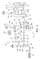
- figure 2 shows a second embodiment according to the invention.
- the numbering of figure 1 has been maintained also in figure 2 for analogous elements.
- the blood treatment apparatus (hemodialysis or hemo(dia)filtration apparatus) of figure 2 comprises a blood treatment unit (hemodialyser or hemo(dia)filter) 2 having a fluid chamber 3, a blood chamber 4, and a semipermeable membrane 5 separating the fluid chamber 3 from the blood chamber 4.
- a blood treatment unit hemodialyser or hemo(dia)filter
- An extracorporeal blood circuit connects a patient vascular access (not shown) with the blood chamber 4.
- the extracorporeal blood circuit comprises an arterial line 7 and a venous line 8.
- the blood treatment apparatus 1 comprises a treatment fluid supply line 9 having a water inlet connected to a water source 10, and a treatment fluid outlet connected to the fluid chamber 3 (hemodialysis treatment) and/or to the arterial line 7 and/or to the venous line 8 (hemodiafiltration/hemofiltration treatment with pre- and/or post-dilution).
- a treatment fluid supply line 9 having a water inlet connected to a water source 10, and a treatment fluid outlet connected to the fluid chamber 3 (hemodialysis treatment) and/or to the arterial line 7 and/or to the venous line 8 (hemodiafiltration/hemofiltration treatment with pre- and/or post-dilution).
- the blood treatment apparatus 1 comprises a preparation device 11 connected to the treatment fluid supply line 9 to prepare the treatment fluid from water and concentrates.
- the treatment fluid is a dialysis fluid (dialysate) which can be used to form a substitution fluid for hemo(dia)filtration treatments.
- the treatment fluid preparation device 11 can comprise a central delivery system connected to the blood treatment apparaus 1, or a device for preparing a fluid from water and concentrates.
- the blood treatment apparatus 1 further comprises a degassing line 12 having an inlet 13 to receive gas-containing fluid coming from the water inlet, and an outlet 14 for supplying degassed fluid to the treatment fluid outlet.
- the treatment fluid supply line 12 has a first junction point, which in this specific case coincides with the inlet 13 of the degassing line 12 and from which the degassing line 12 branches off, and a second junction point, which in this specific case coincides with the outlet 14 of the degassing line 12 and into which the degassing line 12 flows.
- the preparation device 11 is located between the degassed fluid outlet 14 and the treatment fluid outlet.
- a degassing unit 15 is operatively connected to the degassing line 12.
- the degassing unit 15 comprises a gas separator 16 for separating the gas in the gas-containing fluid flowing in the degassing line 12, a flow restrictor 17 for reducing the pressure of the fluid flowing in the degassing line 12, a degassing pump 18 for circulating the fluid in the degassing line 12, a pressure sensor 19 for emitting a pressure signal indicative of the pressure in the degassing line 12, and a control unit 20 designed to control the speed of the degassing pump 18 on the basis of the pressure signal emitted by the pressure sensor 19.
- the gas separator 16 comprises a gas separation chamber.
- the signal used by the control unit 20 to control the degassing pump 18 is a signal indicative of the absolute pressure in the degassing line 12.
- the pressure sensor 19 is an absolute pressure sensor designed to emit an absolute pressure signal.
- the degassing pump 18 has a delivering outlet connected to a fluid inlet of the gas separator 16.
- the degassing pump 18 is located in the degassing line 12 between the restrictor 17 and the gas separator 16.
- the degassing pump 18 is located in the degassing line 12 between the pressure sensor 19 and the gas separator 16.
- the pressure sensor 19 is located in the degassing line 12 between the restrictor 17 and the gas separator 16.
- the pressure sensor 19 is located in the degassing line 12 between the restrictor 17 and the degassing pump 18.
- the degassing pump 18 is a positive displacement pump (e.g. a gear pump).
- the blood treatment apparatus 1 further comprises a discharge line 21 connecting the fluid chamber 3 with a drain.
- the gas separator 16 comprises a gas outlet connected through a vent line 22 to the drain.
- the vent line 22 can be connected to the discharge line 21.
- the vent line 22 is provided with a closing valve 23 controlled by the control unit 20.
- a one-way valve 24 is arranged in the treatment fluid supply line 9 between the first junction point (inlet 13) and the second junction point (outlet 14) so as to block the flow from the inlet 13 to the outlet 14.
- the apparatus of figure 2 further comprises a pressure reductor 25 arranged immediately after the water inlet to control the pressure by restricting the fluid passage.
- a normally closed inlet valve 26 is located downstream the pressure reductor 25.
- the apparatus of figure 2 comprises a first ultrafilter 27 designed to retain bacteria or endotoxin.
- the first ultrafilter has a first chamber (retentate chamber) separated from a second chamber (permeate chamber) by a semipermeble membrane.
- a flushing line 28 connects an outlet of the first chamber of the first ultrafilter with the drain.
- An orifice 29 is arranged in the flushing line 28 to limit the flow rate of fluid flushed through the first chamber and the flushing line 28 and then into the drain.
- a check valve 30 prevents a back-flow coming from the drain polluting the first ultrafilter 27.
- a heater 31 is arranged in the degassing line 12 upstream the restrictor 17 to heat the incoming fluid.
- a temperature sensor 32 measures the temperature of the fluid in the degassing line 12 (downstream of the heater 31).
- the control unit 20 controls the heater 31 to ensure that the temperature measured by the sensor 32 is within a desired range.
- a flow switch 33 is arranged in the degassing line 12. The control unit 20 recognizes an alarm situation (and disconnects the power from the heater 31, for example) when the flow rate through the flow switch 33 is lower than a predetermined value.
- the heater 31 is located downstream of the restrictor 17, e.g. between the restrictor 17 and the degassing pump 18, or between the restrictor 17 and the pressure sensor 19.
- a restrictor bypass valve 34 is arranged in a bypass line connected to the degassing line 12, for bypassing the restrictor 17.
- the restrictor bypass valve 34 which is normally closed, is opened during a heat disinfection procedure - which serves to disinfect the hydraulic circuit of the blood treatment apparatus - and is closed during a blood treatment procedure.
- the restrictor bypass valve 34 is opened during a heat disinfection procedure, the degassing restrictor 17 is bypassed in order to prevent the heated liquid (water) from boiling.
- a pressure regulator 35 is arranged in the treatment fluid supply line 9 between the degassing line 12 and a supply pump 36 circulating a fluid in the treatment fluid supply line 9.
- the pressure regulator 35 is arranged downstrem of the degassing line 12.
- the pressure regulator 35 is set to maintain a desired pressure in the concentrate sources 37a and 37b.
- the concentrate sources comprise cartridges of dry concentrates a moderate overpressure inside the cartridges can be desirable.
- the pressure regulator 35 avoids a too-low pressure causing the formation of gas bubbles upstream of the supply pump 36.
- the pressure regulator 35 prevents or reduces pressure spikes coming from the gas separator 16 (gas separation chamber or bubble trap) during the above-described gas evacuation.
- the treatment fluid (dialysate) preparation device 11 comprises at least two injection lines each operatively associated to a concentrate source 37a and 37b (liquid or solid concentrates), to a dosing pump 38a and 38b, and to a conductivity sensor 39a and 39b controlling a respective dosing pump to a set conductivity value.
- the injection lines are supplied with a solvent (e.g. water) from a line branching off from the treatment fluid supply line 9.
- the apparatus of figure 2 comprises a second ultrafilter 40 designed to retain bacteria or endotoxin.
- the second ultrafilter 40 has a first chamber (retentate chamber) separated from a second chamber (permeate chamber) by a semipermeble membrane.
- a flushing line 41 connects an outlet of the first chamber of the second ultrafilter 40 with the discharge line 21.
- the flushing line 41 is provided with a flushing valve 42 which is periodically (or under predetermined conditions) opened to tangentially flush the second ultrafilter 40.
- a first bypass line 43 is arranged upstream of the second ultrafilter 40 to connect the supply line 9 with the discharge line 21.
- the first bypass line 43 is provided with a first bypass valve 44.
- a second bypass line 45 is arranged downstream of the second ultrafilter 40 to connect the supply line 9 with the discharge line 21.
- the second bypass line 45 is provided with a second bypass valve 46.
- a closing valve 47 is arranged in the discharge line 21 before the second bypass line 45.
- a discharge pump 48 is arranged downstream of the flushing line 41.
- the discharge pump 48 is arranged downstream of the first and second bypass lines 43 and 45.
- the discharge pump 48 circulates the fluid towards the drain.
- a fluid balance system controls the discharge pump 48 (and the supply pump 36) to regulate the weight loss of a patient undergoing a blood treament.
- the fluid balance system comprises an upstream flowmeter 49 arranged before the blood treatment unit 2 in the supply line 9, and a downstream flowmeter 50 arranged after the blood treatment unit 2 in the discharge line 21.
- the control unit 20 is designed to control the degassing pump 18 (during the treatment) at a flow rate which is greater than that of the treatment fluid supply pump 36. During the treatment the valve 34 is closed and the fluid (water) is passed through the degassing restrictor 17.
- the degassing system of the figure 2 apparatus operates as above described in order to reduce gas in the fluid.
- the control unit 20 is designed to control the degassing pump 18 at a predetermined degassing pressure set point.
- the degassing pressure can be set as low as possible in order to maximize the degassing performance, i.e. the removal of oxygen.
- the degassing pressure can be set as low as possible in order to maximize the degassing performance, i.e. the removal of oxygen.
- the degassing pressure can be set. For example, a too-low degassing pressure may result in cavitation in the pump causing increased wear and/or a loss of pump efficiency.
- the selection of the degassing set point may be a trade-off between degassing performance and other requirements such as, e.g., pump life, cost and power consumption.
- a blood treatment apparatus differs from the apparatus of figure 1 (or figure 2 ) only in that the pressure signal that indicates the absolute pressure in the degassing line 12 may be supplied by processing two pressure signals emitted by a first relative pressure sensor arranged in the degassing line 12 (at the same location of the absolute pressure sensor 19) and a second pressure sensor indicating the atmospheric pressure.
- a calculation unit may calculate an absolute pressure value from said two pressure signals, e.g. as a difference between the pressure values indicated by the two pressure signals.
- the control unit 20 may include the calculation unit.
- a blood treatment apparatus differs from the apparatus of figure 1 (or figure 2 ) only in that the degassing line forms a tract (initial, intermediate, or final tract) of the treatment fluid supply line without forming a loop between two junction points thereof.
- the degassing line and the treatment fluid supply line form a continuous fluid line, whereby the flow rate of the degassing line is equal to the flow rate of the treatment fluid supply line and the supply pump of the treatment fluid supply line may act as degassing pump of the degassing line.
Landscapes
- Health & Medical Sciences (AREA)
- Heart & Thoracic Surgery (AREA)
- Urology & Nephrology (AREA)
- Anesthesiology (AREA)
- Vascular Medicine (AREA)
- Engineering & Computer Science (AREA)
- Emergency Medicine (AREA)
- Biomedical Technology (AREA)
- Hematology (AREA)
- Life Sciences & Earth Sciences (AREA)
- Animal Behavior & Ethology (AREA)
- General Health & Medical Sciences (AREA)
- Public Health (AREA)
- Veterinary Medicine (AREA)
- External Artificial Organs (AREA)
Claims (15)
- Blutbehandlungsvorrichtung (1) umfassend:eine Blutbehandlungseinheit (2) mit einem Fluidabteil (3), einem Blutabteil (4) und einer semipermeablen Membran (5), die den Fluidabteil (3) vom Blutabteil (4) trennt;einen extrakorporalen Blutkreislauf (7; 8), der einen Patientengefäßzugang (6) mit dem Blutabteil (4) verbindet;eine Behandlungsfluidversorgungsleitung (9) umfassend einen gasenthaltenden Fluideingang, der mit einer gasenthaltenden Fluidquelle (10) verbunden ist, und einen Behandlungsfluidausgang, der mit dem Fluidabteil (3) und mit dem extrakorporalen Blutkreislauf (7; 8) verbunden ist;eine Entgasungsleitung (12) mit einem Entgasungsleitungseingang (13) zum Empfang von gasenthaltendem Fluid vom gasenthaltenden Fluideingang, und mit einem Entgasungsleitungsausgang (14) zur Versorgung von entgastem Fluid zum Behandlungsfluidausgang;eine Entgasungseinheit (15), die mit der Entgasungsleitung (12) operativ verbunden ist, wobei die Entgasungseinheit (15) folgendes umfasst:eine Entgasungspumpe (18) zum Strömen des Fluids in der Entgasungsleitung (12) vom Entgasungsleitungseingang (13) zum Entgasungsleitungsausgang (14),einen Gasabscheider (16) zum Abscheiden des Gases im gasenthaltenden Fluid, das in der Entgasungsleitung (12) strömt, undeinen Durchsatzbegrenzer (17) zur Verminderung des Druckes des in der Entgasungsleitung (12) strömenden Fluids,dadurch gekennzeichnet, daß die Vorrichtung weiter umfasst:ein Absolutdrucksensormittel (19) zum Senden eines Absolutdrucksignals, der einen Absolutdruck in der Entgasungsleitung (12) darstellt, undeine Steuereinheit (20) zur Steuerung der Geschwindigkeit der Entgasungspumpe (18) aus dem Absolutdrucksignal.
- Vorrichtung nach Anspruch 1, umfassend eine Abflussleitung (21), die den Fluidabteil (3) mit einem Ablass verbindet.
- Vorrichtung nach dem vorhergehenden Anspruch, wobei der Gasabscheider (16) einen Gasausgang umfasst, der durch eine Entlüftungsleitung (22) mit der Abflussleitung (21) verbunden ist, wobei der Gasabscheider (16) insbesondere einen Gasabscheidungsabteil umfasst.
- Vorrichtung nach einem der vorhergehenden Ansprüche, wobei die Entgasungspumpe (18) einen Versorgungsausgang besitzt, der mit einem Fluideingang des Gasabscheiders (16) verbunden ist.
- Vorrichtung nach einem der vorhergehenden Ansprüche, umfassend eine Heizeinrichtung (31), die sich in der Entgasungsleitung (12) befindet, um das in der Entgasungsleitung (12) strömende Fluid zu erhitzen.
- Vorrichtung nach dem vorhergehenden Anspruch, wobei der Durchsatzbegrenzer (17) sich in der Entgasungsleitung (12) zwischen der Heizeinrichtung (31) und dem Gasabscheider (16) oder der Entgasungspumpe (18) befindet.
- Vorrichtung nach Anspruch 5, wobei die Heizeinrichtung (31) sich in der Entgasungsleitung (12) zwischen dem Durchsatzbegrenzer (17) und der Entgasungspumpe (18) oder dem Absolutdrucksensormittel (19) befindet, oder wobei die Heizeinrichtung (31) sich in der Entgasungsleitung (12) abwärts vom Durchsatzbegrenzer (17) befindet, oder wobei die Heizeinrichtung (31) sich in der Entgasungsleitung (12) abwärts vom Absolutdrucksensormittel (19) befindet.
- Vorrichtung nach einem der vorhergehenden Ansprüche, wobei die Entgasungspumpe' (18) sich in der Entgasungsleitung (12) zwischen dem Durchsatzbegrenzer (17) und dem Gasabscheider (16) befindet oder wobei die Entgasungspumpe (18) sich in der Entgasungsleitung (12) zwischen dem Absolutdrucksensormittel (19) und dem Gasabscheider (16) befindet.
- Vorrichtung nach einem der vorhergehenden Ansprüche, wobei die Absolutdrucksensormittel (19) sich in der Entgasungsleitung (12) zwischen dem Durchsatzbegrenzer (17) und dem Gasabscheider (16) befinden, oder die Absolutdrucksensormittel (19) sich in der Entgasungsleitung (12) zwischen dem Durchsatzbegrenzer (17) und der Entgasungspumpe (18) befinden, oder wobei die Absolutdrucksensormittel (19) sich in der Entgasungsleitung (12) abwärts vom Durchsatzbegrenzer (17) befinden.
- Vorrichtung nach einem der vorhergehenden Ansprüche, weiter umfassend eine Behandlungsfluidvorbereitungsvorrichtung (11), die mit der Behandlungsfluidversorgungsleitung (9) verbunden ist, um das Behandlungsfluid aus Wasser und Konzentraten vorzubereiten.
- Vorrichtung nach dem vorhergehenden Anspruch, wobei die Behandlungsfluidvorbereitungsvorrichtung (11) sich zwischen dem Entgasungsleitungsausgang (14) und dem Behandlungsfluidausgang befindet.
- Vorrichtung nach einem der vorhergehenden Ansprüche, wobei die Behandlungsfluidversorgungsleitung (9) eine erste Verbindungsstelle (13) und eine zweite Verbindungsstelle (14) besitzt, wobei die Entgasungsleitung (12) einen Ring zwischen der ersten Verbindungsstelle (13) und der zweiten Verbindungsstelle (14) bildet, wobei ein Einwegventil (24) insbesondere in der Behandlungsfluidversorgungsleitung (9) zwischen der ersten Verbindungsstelle (13) und der zweiten Verbindungsstelle (14) angeordnet ist.
- Vorrichtung nach einem der vorhergehenden Ansprüche, umfassend eine Behandlungsfluidversorgungspumpe (36) zur Fluidverdrängung durch die Behandlungsversorgungsleitung (9), wobei die Behandlungsfluidversorgungspumpe (36) insbesondere in der Behandlungsversorgungsleitung (9) angeordnet ist.
- Vorrichtung nach Anspruch 12 oder 13, wobei die Steuereinheit (20) zur Steuerung der Behandlungsfluidversorgungspumpe (36) zur Fluidströmung durch die Behandlungsversorgungsleitung (9) bei einer ersten Durchsatzmenge und zur Steuerung der Entgasungspumpe (18) zur Fluidströmung durch die Entgasungsleitung (12) bei einer zweiten Durchsatzmenge vorgesehen ist, wobei die erste Durchsatzmenge kleiner ist als die zweite Durchsatzmenge.
- Vorrichtung nach einem der vorhergehenden Ansprüche, wobei das Absolutdrucksensormittel einen ersten Drucksensor zum Senden eines ersten Drucksignals, der einen Relativdruck in der Entgasungsleitung (12) darstellt, einen zweiten Drucksensor zum Senden eines zweiten Drucksignals, der den Luftdruck darstellt, und eine Recheneinheit (20) zum Berechnen eines Absolutdruckwertes aus den ersten und zweiten Drucksignalen umfasst.
Applications Claiming Priority (1)
| Application Number | Priority Date | Filing Date | Title |
|---|---|---|---|
| PCT/IB2006/003434 WO2008065470A1 (en) | 2006-12-01 | 2006-12-01 | Blood treatment apparatus |
Publications (2)
| Publication Number | Publication Date |
|---|---|
| EP2101841A1 EP2101841A1 (de) | 2009-09-23 |
| EP2101841B1 true EP2101841B1 (de) | 2011-09-14 |
Family
ID=38268707
Family Applications (1)
| Application Number | Title | Priority Date | Filing Date |
|---|---|---|---|
| EP06831620A Not-in-force EP2101841B1 (de) | 2006-12-01 | 2006-12-01 | Blutbehandlungsgerät |
Country Status (6)
| Country | Link |
|---|---|
| US (1) | US8449487B2 (de) |
| EP (1) | EP2101841B1 (de) |
| AT (1) | ATE524204T1 (de) |
| CA (1) | CA2671010C (de) |
| ES (1) | ES2370985T3 (de) |
| WO (1) | WO2008065470A1 (de) |
Cited By (1)
| Publication number | Priority date | Publication date | Assignee | Title |
|---|---|---|---|---|
| RU2537583C2 (ru) * | 2012-03-10 | 2015-01-10 | ФЁЛЬКЕР Манфред | Смесительное устройство для приготовления готовых к употреблению медицинских промывочных растворов, прежде всего концентратов для гемодиализа |
Families Citing this family (63)
| Publication number | Priority date | Publication date | Assignee | Title |
|---|---|---|---|---|
| ES2447296T3 (es) | 2006-10-13 | 2014-03-11 | Bluesky Medical Group Incorporated | Control de presión de una bomba de vacío médica |
| US9408954B2 (en) | 2007-07-02 | 2016-08-09 | Smith & Nephew Plc | Systems and methods for controlling operation of negative pressure wound therapy apparatus |
| GB0715259D0 (en) | 2007-08-06 | 2007-09-12 | Smith & Nephew | Canister status determination |
| GB0715211D0 (en) * | 2007-08-06 | 2007-09-12 | Smith & Nephew | Apparatus |
| US12121648B2 (en) | 2007-08-06 | 2024-10-22 | Smith & Nephew Plc | Canister status determination |
| US9358331B2 (en) | 2007-09-13 | 2016-06-07 | Fresenius Medical Care Holdings, Inc. | Portable dialysis machine with improved reservoir heating system |
| US8105487B2 (en) | 2007-09-25 | 2012-01-31 | Fresenius Medical Care Holdings, Inc. | Manifolds for use in conducting dialysis |
| US8137553B2 (en) | 2007-11-29 | 2012-03-20 | Fresenius Medical Care Holdings, Inc. | Priming system and method for dialysis systems |
| US9308307B2 (en) | 2007-09-13 | 2016-04-12 | Fresenius Medical Care Holdings, Inc. | Manifold diaphragms |
| US8240636B2 (en) | 2009-01-12 | 2012-08-14 | Fresenius Medical Care Holdings, Inc. | Valve system |
| US8597505B2 (en) | 2007-09-13 | 2013-12-03 | Fresenius Medical Care Holdings, Inc. | Portable dialysis machine |
| US9199022B2 (en) | 2008-09-12 | 2015-12-01 | Fresenius Medical Care Holdings, Inc. | Modular reservoir assembly for a hemodialysis and hemofiltration system |
| EP3511034B1 (de) | 2007-11-29 | 2023-03-29 | Fresenius Medical Care Holdings, Inc. | System zur extrakorporalen blutbehandlung und durchführung von hämodialyse und hämofiltration |
| CA2739807C (en) | 2008-10-30 | 2017-02-28 | Fresenius Medical Care Holdings, Inc. | Modular, portable dialysis system |
| DE102009026060B4 (de) * | 2009-06-29 | 2018-05-24 | Fresenius Medical Care Deutschland Gmbh | Verfahren zur Präparierung und Aufrüstung einer Hämodialysemaschine zur Durchführung einer Hämodialysebehandlung sowie Hämodialysemaschine |
| US8409445B2 (en) | 2009-11-25 | 2013-04-02 | Fresenius Medical Care Holdings, Inc. | Method for removing gases from a container having a powdered concentrate for use in hemodialysis |
| US8585907B2 (en) * | 2009-11-25 | 2013-11-19 | Fresenius Medical Care Holdings, Inc. | Method for removing gases from a container having a powdered concentrate for use in hemodialysis |
| US8753515B2 (en) | 2009-12-05 | 2014-06-17 | Home Dialysis Plus, Ltd. | Dialysis system with ultrafiltration control |
| KR101936276B1 (ko) | 2010-01-21 | 2019-01-08 | 더 아벨 파운데이션, 인크. | 해양 온도차 발전소 |
| US8501009B2 (en) | 2010-06-07 | 2013-08-06 | State Of Oregon Acting By And Through The State Board Of Higher Education On Behalf Of Oregon State University | Fluid purification system |
| US9375524B2 (en) | 2011-06-03 | 2016-06-28 | Fresenius Medical Care Holdings, Inc. | Method and arrangement for venting gases from a container having a powdered concentrate for use in hemodialysis |
| DE102011106111B4 (de) * | 2011-06-09 | 2013-11-21 | Fresenius Medical Care Deutschland Gmbh | Verfahren und Vorrichiung zum Bestimmen mindestens eines vom Absolutdruck abhängigen Betriebsparameters einer Vorrichtung zur extrakorporalen Blutbehandlung, Vorrichtung zur extrakorporalen Blutbehandlung |
| CN103889481B (zh) | 2011-08-02 | 2016-03-09 | 美敦力公司 | 带有具有可控的顺应性容积的流动路径的血液透析系统 |
| WO2013025844A2 (en) | 2011-08-16 | 2013-02-21 | Medtronic, Inc. | Modular hemodialysis system |
| US9328969B2 (en) | 2011-10-07 | 2016-05-03 | Outset Medical, Inc. | Heat exchange fluid purification for dialysis system |
| JP5872321B2 (ja) * | 2012-02-24 | 2016-03-01 | 柴田 猛 | 透析液・原液水素還元装置 |
| DE102012004970A1 (de) * | 2012-03-14 | 2013-09-19 | Fresenius Medical Care Deutschland Gmbh | Verfahren zum Dosieren eines mittels einer Blutbehandlungsvorrichtung erzeugten Substituats sowie Vorrichtungen |
| GB2505700B (en) * | 2012-09-10 | 2020-02-12 | Tco As | Injection device |
| US9201036B2 (en) | 2012-12-21 | 2015-12-01 | Fresenius Medical Care Holdings, Inc. | Method and system of monitoring electrolyte levels and composition using capacitance or induction |
| US9157786B2 (en) | 2012-12-24 | 2015-10-13 | Fresenius Medical Care Holdings, Inc. | Load suspension and weighing system for a dialysis machine reservoir |
| US11154648B2 (en) | 2013-01-09 | 2021-10-26 | Medtronic, Inc. | Fluid circuits for sorbent cartridge with sensors |
| US9713666B2 (en) | 2013-01-09 | 2017-07-25 | Medtronic, Inc. | Recirculating dialysate fluid circuit for blood measurement |
| US10543052B2 (en) | 2013-02-01 | 2020-01-28 | Medtronic, Inc. | Portable dialysis cabinet |
| US10010663B2 (en) | 2013-02-01 | 2018-07-03 | Medtronic, Inc. | Fluid circuit for delivery of renal replacement therapies |
| US10850016B2 (en) | 2013-02-01 | 2020-12-01 | Medtronic, Inc. | Modular fluid therapy system having jumpered flow paths and systems and methods for cleaning and disinfection |
| US9623164B2 (en) | 2013-02-01 | 2017-04-18 | Medtronic, Inc. | Systems and methods for multifunctional volumetric fluid control |
| US9354640B2 (en) | 2013-11-11 | 2016-05-31 | Fresenius Medical Care Holdings, Inc. | Smart actuator for valve |
| US9884145B2 (en) | 2013-11-26 | 2018-02-06 | Medtronic, Inc. | Parallel modules for in-line recharging of sorbents using alternate duty cycles |
| US10537875B2 (en) | 2013-11-26 | 2020-01-21 | Medtronic, Inc. | Precision recharging of sorbent materials using patient and session data |
| JP6657186B2 (ja) | 2014-04-29 | 2020-03-04 | アウトセット・メディカル・インコーポレイテッドOutset Medical, Inc. | 透析システムおよび方法 |
| US10357757B2 (en) | 2014-06-24 | 2019-07-23 | Medtronic, Inc. | Stacked sorbent assembly |
| ES2989503T3 (es) | 2014-06-24 | 2024-11-26 | Mozarc Medical Us Llc | Conjunto modular de regeneración de dialisato |
| WO2016049542A2 (en) | 2014-09-25 | 2016-03-31 | Nxstage Medical, Inc. | Medicament preparation and treatment devices, methods, and systems |
| US10874787B2 (en) | 2014-12-10 | 2020-12-29 | Medtronic, Inc. | Degassing system for dialysis |
| US10098993B2 (en) | 2014-12-10 | 2018-10-16 | Medtronic, Inc. | Sensing and storage system for fluid balance |
| US9713665B2 (en) | 2014-12-10 | 2017-07-25 | Medtronic, Inc. | Degassing system for dialysis |
| DE102015005179B4 (de) * | 2015-04-22 | 2022-07-28 | Fresenius Medical Care Deutschland Gmbh | Dialysemaschine und Verfahren zum Betrieb eines Pneumatiksystems einer Dialysemaschine |
| US10360813B2 (en) * | 2015-08-20 | 2019-07-23 | Osaka University | Pulsatile pump for catheter simulator |
| DE102015012604B4 (de) * | 2015-09-28 | 2025-05-08 | Fresenius Medical Care Deutschland Gmbh | Dialysegerät |
| EP3500317B1 (de) | 2016-08-19 | 2022-02-23 | Outset Medical, Inc. | Peritonealdialysesystem und -verfahren |
| US10981148B2 (en) | 2016-11-29 | 2021-04-20 | Medtronic, Inc. | Zirconium oxide module conditioning |
| US10960381B2 (en) | 2017-06-15 | 2021-03-30 | Medtronic, Inc. | Zirconium phosphate disinfection recharging and conditioning |
| US11278654B2 (en) | 2017-12-07 | 2022-03-22 | Medtronic, Inc. | Pneumatic manifold for a dialysis system |
| EP3505199B1 (de) * | 2017-12-28 | 2020-04-01 | Gambro Lundia AB | Vorrichtung zur extrakorporalen behandlung von blut |
| US11033667B2 (en) | 2018-02-02 | 2021-06-15 | Medtronic, Inc. | Sorbent manifold for a dialysis system |
| US11110215B2 (en) | 2018-02-23 | 2021-09-07 | Medtronic, Inc. | Degasser and vent manifolds for dialysis |
| US12285552B2 (en) | 2018-08-14 | 2025-04-29 | Mozarc Medical Us Llc | Precision dialysis therapy based on sorbent effluent analysis |
| US12201762B2 (en) | 2018-08-23 | 2025-01-21 | Outset Medical, Inc. | Dialysis system and methods |
| US11213616B2 (en) | 2018-08-24 | 2022-01-04 | Medtronic, Inc. | Recharge solution for zirconium phosphate |
| US12128165B2 (en) | 2020-04-27 | 2024-10-29 | Mozarc Medical Us Llc | Dual stage degasser |
| RU2747084C1 (ru) * | 2020-10-15 | 2021-04-26 | Общество с ограниченной ответственностью "ДорАгроМаш" ООО "ДорАгроМаш" | Растворный узел |
| EP3991764B1 (de) * | 2020-10-27 | 2024-03-06 | Bellco S.r.l. | Durchflussmesser zum dosieren von wasser in einem dialysesystem |
| US12318528B2 (en) | 2020-10-30 | 2025-06-03 | Mozarc Medical Us Llc | Variable orifice fistula graft |
Family Cites Families (21)
| Publication number | Priority date | Publication date | Assignee | Title |
|---|---|---|---|---|
| NO119547B (de) * | 1967-07-04 | 1970-06-01 | Nyctron A S | |
| NO121008B (de) * | 1969-11-11 | 1971-01-04 | Nycotron As | |
| FR2126610A5 (en) * | 1971-02-12 | 1972-10-06 | Thomson Csf | Liquid degasifier - with recycling to obtain complete degasification |
| US3878095A (en) * | 1974-05-02 | 1975-04-15 | Advanced Medical Sciences Inc | Dialysis apparatus |
| US4348280A (en) * | 1974-10-21 | 1982-09-07 | Baxter Travenol Laboratories, Inc. | Proportioning dialysis machine |
| US4153554A (en) * | 1977-02-22 | 1979-05-08 | American Micro-Bionics Corp. | Apparatus for use in artificial kidney system |
| US4229299A (en) * | 1978-03-22 | 1980-10-21 | Hoechst Aktiengesellschaft | Peristaltic dialysate solution pump |
| US4298357A (en) * | 1978-07-10 | 1981-11-03 | Baxter Travenol Laboratories, Inc. | Degassing system |
| DE3418434C2 (de) | 1984-05-18 | 1986-06-05 | Fresenius AG, 6380 Bad Homburg | Verfahren zum Füllen des Blutschlauchsystems und des Dialysators einer Hämodialysevorrichtung mit einer physiologischen Kochsalzlösung sowie Vorrichtung hierzu |
| US4828693A (en) * | 1987-09-22 | 1989-05-09 | Baxter Travenol Laboratories, Inc. | Water pressure regulator for hemodialysis apparatus |
| DE3837498A1 (de) * | 1988-11-04 | 1990-05-17 | Fresenius Ag | Verfahren und vorrichtung zur ultrafiltration bei der haemodialyse |
| US5486286A (en) * | 1991-04-19 | 1996-01-23 | Althin Medical, Inc. | Apparatus for performing a self-test of kidney dialysis membrane |
| US5624551A (en) * | 1993-04-28 | 1997-04-29 | Fresenius Ag | Hydraulic safety circuit for a hemodialysis apparatus |
| US5591344A (en) * | 1995-02-13 | 1997-01-07 | Aksys, Ltd. | Hot water disinfection of dialysis machines, including the extracorporeal circuit thereof |
| SE9901165D0 (sv) | 1999-03-30 | 1999-03-30 | Gambro Lundia Ab | Method, apparatus and components of dialysis systems |
| JP4129866B2 (ja) * | 2002-07-18 | 2008-08-06 | 日機装株式会社 | 血液処理装置 |
| US8038639B2 (en) * | 2004-11-04 | 2011-10-18 | Baxter International Inc. | Medical fluid system with flexible sheeting disposable unit |
| SE0400330D0 (sv) * | 2004-02-12 | 2004-02-12 | Gambro Lundia Ab | Pressure sensing |
| US7473395B2 (en) * | 2004-08-17 | 2009-01-06 | Zviman Menekhem M | Hypothermia induction device |
| JP4566262B2 (ja) * | 2005-07-01 | 2010-10-20 | ガンブロ・ルンディア・エービー | フィルタを検査するための装置および方法 |
| CA2667604C (en) * | 2006-10-30 | 2011-07-12 | Gambro Lundia Ab | Medical fluid circuit unit |
-
2006
- 2006-12-01 CA CA2671010A patent/CA2671010C/en not_active Expired - Fee Related
- 2006-12-01 WO PCT/IB2006/003434 patent/WO2008065470A1/en active Application Filing
- 2006-12-01 EP EP06831620A patent/EP2101841B1/de not_active Not-in-force
- 2006-12-01 ES ES06831620T patent/ES2370985T3/es active Active
- 2006-12-01 US US12/516,786 patent/US8449487B2/en active Active
- 2006-12-01 AT AT06831620T patent/ATE524204T1/de not_active IP Right Cessation
Cited By (1)
| Publication number | Priority date | Publication date | Assignee | Title |
|---|---|---|---|---|
| RU2537583C2 (ru) * | 2012-03-10 | 2015-01-10 | ФЁЛЬКЕР Манфред | Смесительное устройство для приготовления готовых к употреблению медицинских промывочных растворов, прежде всего концентратов для гемодиализа |
Also Published As
| Publication number | Publication date |
|---|---|
| ES2370985T3 (es) | 2011-12-26 |
| ATE524204T1 (de) | 2011-09-15 |
| US8449487B2 (en) | 2013-05-28 |
| EP2101841A1 (de) | 2009-09-23 |
| CA2671010C (en) | 2012-04-24 |
| WO2008065470A1 (en) | 2008-06-05 |
| US20100106071A1 (en) | 2010-04-29 |
| CA2671010A1 (en) | 2008-06-05 |
Similar Documents
| Publication | Publication Date | Title |
|---|---|---|
| EP2101841B1 (de) | Blutbehandlungsgerät | |
| US8480609B2 (en) | Apparatus for extracorporeal blood treatment | |
| JP4235555B2 (ja) | 体外回路のプライミング方法および透析装置 | |
| US9452251B2 (en) | Degassing membrane for dialysis | |
| US6716356B2 (en) | Thermally enhanced dialysis/diafiltration system | |
| EP1392376B1 (de) | Vorrichtung zur herstellung eines dialysats für ein dialysegerät | |
| JP2007244918A (ja) | 2ステージ型透析濾過方法および装置 | |
| JP2004518462A (ja) | 滅菌輸液を生成するための方法および装置 | |
| EP1137482B2 (de) | Anlage zur nicht-isosmotischen diafiltration | |
| EP1698362B1 (de) | Blutbehandlungsmaschine sowie Blutbehandlungseinheit | |
| US20210213189A1 (en) | Blood purification apparatus | |
| US20230040372A1 (en) | A system and method for producing fluid for peritoneal dialysis | |
| CN111511418A (zh) | 具有二氧化碳生成和灌注的透析系统 | |
| JPS6214861A (ja) | 人工腎臓装置 |
Legal Events
| Date | Code | Title | Description |
|---|---|---|---|
| PUAI | Public reference made under article 153(3) epc to a published international application that has entered the european phase |
Free format text: ORIGINAL CODE: 0009012 |
|
| 17P | Request for examination filed |
Effective date: 20090622 |
|
| AK | Designated contracting states |
Kind code of ref document: A1 Designated state(s): AT BE BG CH CY CZ DE DK EE ES FI FR GB GR HU IE IS IT LI LT LU LV MC NL PL PT RO SE SI SK TR |
|
| DAX | Request for extension of the european patent (deleted) | ||
| GRAP | Despatch of communication of intention to grant a patent |
Free format text: ORIGINAL CODE: EPIDOSNIGR1 |
|
| GRAS | Grant fee paid |
Free format text: ORIGINAL CODE: EPIDOSNIGR3 |
|
| GRAA | (expected) grant |
Free format text: ORIGINAL CODE: 0009210 |
|
| AK | Designated contracting states |
Kind code of ref document: B1 Designated state(s): AT BE BG CH CY CZ DE DK EE ES FI FR GB GR HU IE IS IT LI LT LU LV MC NL PL PT RO SE SI SK TR |
|
| REG | Reference to a national code |
Ref country code: GB Ref legal event code: FG4D |
|
| REG | Reference to a national code |
Ref country code: CH Ref legal event code: EP |
|
| REG | Reference to a national code |
Ref country code: IE Ref legal event code: FG4D |
|
| REG | Reference to a national code |
Ref country code: DE Ref legal event code: R096 Ref document number: 602006024463 Country of ref document: DE Effective date: 20111110 |
|
| REG | Reference to a national code |
Ref country code: ES Ref legal event code: FG2A Ref document number: 2370985 Country of ref document: ES Kind code of ref document: T3 Effective date: 20111226 |
|
| REG | Reference to a national code |
Ref country code: NL Ref legal event code: VDEP Effective date: 20110914 |
|
| PG25 | Lapsed in a contracting state [announced via postgrant information from national office to epo] |
Ref country code: LT Free format text: LAPSE BECAUSE OF FAILURE TO SUBMIT A TRANSLATION OF THE DESCRIPTION OR TO PAY THE FEE WITHIN THE PRESCRIBED TIME-LIMIT Effective date: 20110914 Ref country code: FI Free format text: LAPSE BECAUSE OF FAILURE TO SUBMIT A TRANSLATION OF THE DESCRIPTION OR TO PAY THE FEE WITHIN THE PRESCRIBED TIME-LIMIT Effective date: 20110914 Ref country code: SE Free format text: LAPSE BECAUSE OF FAILURE TO SUBMIT A TRANSLATION OF THE DESCRIPTION OR TO PAY THE FEE WITHIN THE PRESCRIBED TIME-LIMIT Effective date: 20110914 |
|
| LTIE | Lt: invalidation of european patent or patent extension |
Effective date: 20110914 |
|
| PG25 | Lapsed in a contracting state [announced via postgrant information from national office to epo] |
Ref country code: AT Free format text: LAPSE BECAUSE OF FAILURE TO SUBMIT A TRANSLATION OF THE DESCRIPTION OR TO PAY THE FEE WITHIN THE PRESCRIBED TIME-LIMIT Effective date: 20110914 Ref country code: GR Free format text: LAPSE BECAUSE OF FAILURE TO SUBMIT A TRANSLATION OF THE DESCRIPTION OR TO PAY THE FEE WITHIN THE PRESCRIBED TIME-LIMIT Effective date: 20111215 Ref country code: CY Free format text: LAPSE BECAUSE OF FAILURE TO SUBMIT A TRANSLATION OF THE DESCRIPTION OR TO PAY THE FEE WITHIN THE PRESCRIBED TIME-LIMIT Effective date: 20110914 Ref country code: LV Free format text: LAPSE BECAUSE OF FAILURE TO SUBMIT A TRANSLATION OF THE DESCRIPTION OR TO PAY THE FEE WITHIN THE PRESCRIBED TIME-LIMIT Effective date: 20110914 Ref country code: SI Free format text: LAPSE BECAUSE OF FAILURE TO SUBMIT A TRANSLATION OF THE DESCRIPTION OR TO PAY THE FEE WITHIN THE PRESCRIBED TIME-LIMIT Effective date: 20110914 |
|
| REG | Reference to a national code |
Ref country code: AT Ref legal event code: MK05 Ref document number: 524204 Country of ref document: AT Kind code of ref document: T Effective date: 20110914 |
|
| PG25 | Lapsed in a contracting state [announced via postgrant information from national office to epo] |
Ref country code: BE Free format text: LAPSE BECAUSE OF FAILURE TO SUBMIT A TRANSLATION OF THE DESCRIPTION OR TO PAY THE FEE WITHIN THE PRESCRIBED TIME-LIMIT Effective date: 20110914 |
|
| PG25 | Lapsed in a contracting state [announced via postgrant information from national office to epo] |
Ref country code: SK Free format text: LAPSE BECAUSE OF FAILURE TO SUBMIT A TRANSLATION OF THE DESCRIPTION OR TO PAY THE FEE WITHIN THE PRESCRIBED TIME-LIMIT Effective date: 20110914 Ref country code: IS Free format text: LAPSE BECAUSE OF FAILURE TO SUBMIT A TRANSLATION OF THE DESCRIPTION OR TO PAY THE FEE WITHIN THE PRESCRIBED TIME-LIMIT Effective date: 20120114 Ref country code: CZ Free format text: LAPSE BECAUSE OF FAILURE TO SUBMIT A TRANSLATION OF THE DESCRIPTION OR TO PAY THE FEE WITHIN THE PRESCRIBED TIME-LIMIT Effective date: 20110914 |
|
| PG25 | Lapsed in a contracting state [announced via postgrant information from national office to epo] |
Ref country code: EE Free format text: LAPSE BECAUSE OF FAILURE TO SUBMIT A TRANSLATION OF THE DESCRIPTION OR TO PAY THE FEE WITHIN THE PRESCRIBED TIME-LIMIT Effective date: 20110914 Ref country code: RO Free format text: LAPSE BECAUSE OF FAILURE TO SUBMIT A TRANSLATION OF THE DESCRIPTION OR TO PAY THE FEE WITHIN THE PRESCRIBED TIME-LIMIT Effective date: 20110914 Ref country code: PT Free format text: LAPSE BECAUSE OF FAILURE TO SUBMIT A TRANSLATION OF THE DESCRIPTION OR TO PAY THE FEE WITHIN THE PRESCRIBED TIME-LIMIT Effective date: 20120116 Ref country code: NL Free format text: LAPSE BECAUSE OF FAILURE TO SUBMIT A TRANSLATION OF THE DESCRIPTION OR TO PAY THE FEE WITHIN THE PRESCRIBED TIME-LIMIT Effective date: 20110914 Ref country code: PL Free format text: LAPSE BECAUSE OF FAILURE TO SUBMIT A TRANSLATION OF THE DESCRIPTION OR TO PAY THE FEE WITHIN THE PRESCRIBED TIME-LIMIT Effective date: 20110914 |
|
| PLBE | No opposition filed within time limit |
Free format text: ORIGINAL CODE: 0009261 |
|
| STAA | Information on the status of an ep patent application or granted ep patent |
Free format text: STATUS: NO OPPOSITION FILED WITHIN TIME LIMIT |
|
| PG25 | Lapsed in a contracting state [announced via postgrant information from national office to epo] |
Ref country code: DK Free format text: LAPSE BECAUSE OF FAILURE TO SUBMIT A TRANSLATION OF THE DESCRIPTION OR TO PAY THE FEE WITHIN THE PRESCRIBED TIME-LIMIT Effective date: 20110914 Ref country code: MC Free format text: LAPSE BECAUSE OF NON-PAYMENT OF DUE FEES Effective date: 20111231 |
|
| REG | Reference to a national code |
Ref country code: CH Ref legal event code: PL |
|
| 26N | No opposition filed |
Effective date: 20120615 |
|
| REG | Reference to a national code |
Ref country code: IE Ref legal event code: MM4A |
|
| REG | Reference to a national code |
Ref country code: DE Ref legal event code: R097 Ref document number: 602006024463 Country of ref document: DE Effective date: 20120615 |
|
| PG25 | Lapsed in a contracting state [announced via postgrant information from national office to epo] |
Ref country code: LI Free format text: LAPSE BECAUSE OF NON-PAYMENT OF DUE FEES Effective date: 20111231 Ref country code: IE Free format text: LAPSE BECAUSE OF NON-PAYMENT OF DUE FEES Effective date: 20111201 Ref country code: CH Free format text: LAPSE BECAUSE OF NON-PAYMENT OF DUE FEES Effective date: 20111231 |
|
| PG25 | Lapsed in a contracting state [announced via postgrant information from national office to epo] |
Ref country code: LU Free format text: LAPSE BECAUSE OF NON-PAYMENT OF DUE FEES Effective date: 20111201 |
|
| PG25 | Lapsed in a contracting state [announced via postgrant information from national office to epo] |
Ref country code: BG Free format text: LAPSE BECAUSE OF FAILURE TO SUBMIT A TRANSLATION OF THE DESCRIPTION OR TO PAY THE FEE WITHIN THE PRESCRIBED TIME-LIMIT Effective date: 20111214 |
|
| PG25 | Lapsed in a contracting state [announced via postgrant information from national office to epo] |
Ref country code: TR Free format text: LAPSE BECAUSE OF FAILURE TO SUBMIT A TRANSLATION OF THE DESCRIPTION OR TO PAY THE FEE WITHIN THE PRESCRIBED TIME-LIMIT Effective date: 20110914 |
|
| PG25 | Lapsed in a contracting state [announced via postgrant information from national office to epo] |
Ref country code: HU Free format text: LAPSE BECAUSE OF FAILURE TO SUBMIT A TRANSLATION OF THE DESCRIPTION OR TO PAY THE FEE WITHIN THE PRESCRIBED TIME-LIMIT Effective date: 20110914 |
|
| REG | Reference to a national code |
Ref country code: FR Ref legal event code: PLFP Year of fee payment: 10 |
|
| REG | Reference to a national code |
Ref country code: FR Ref legal event code: PLFP Year of fee payment: 11 |
|
| REG | Reference to a national code |
Ref country code: FR Ref legal event code: PLFP Year of fee payment: 12 |
|
| PGFP | Annual fee paid to national office [announced via postgrant information from national office to epo] |
Ref country code: DE Payment date: 20181119 Year of fee payment: 13 |
|
| PGFP | Annual fee paid to national office [announced via postgrant information from national office to epo] |
Ref country code: IT Payment date: 20181019 Year of fee payment: 13 Ref country code: FR Payment date: 20181120 Year of fee payment: 13 Ref country code: GB Payment date: 20181127 Year of fee payment: 13 |
|
| PGFP | Annual fee paid to national office [announced via postgrant information from national office to epo] |
Ref country code: ES Payment date: 20190107 Year of fee payment: 13 |
|
| REG | Reference to a national code |
Ref country code: DE Ref legal event code: R119 Ref document number: 602006024463 Country of ref document: DE |
|
| GBPC | Gb: european patent ceased through non-payment of renewal fee |
Effective date: 20191201 |
|
| PG25 | Lapsed in a contracting state [announced via postgrant information from national office to epo] |
Ref country code: FR Free format text: LAPSE BECAUSE OF NON-PAYMENT OF DUE FEES Effective date: 20191231 Ref country code: GB Free format text: LAPSE BECAUSE OF NON-PAYMENT OF DUE FEES Effective date: 20191201 Ref country code: IT Free format text: LAPSE BECAUSE OF NON-PAYMENT OF DUE FEES Effective date: 20191201 Ref country code: DE Free format text: LAPSE BECAUSE OF NON-PAYMENT OF DUE FEES Effective date: 20200701 |
|
| REG | Reference to a national code |
Ref country code: ES Ref legal event code: FD2A Effective date: 20210601 |
|
| PG25 | Lapsed in a contracting state [announced via postgrant information from national office to epo] |
Ref country code: ES Free format text: LAPSE BECAUSE OF NON-PAYMENT OF DUE FEES Effective date: 20191202 |