EP2101297A1 - Verfahren zum Kalibrieren eines Bühne-Kamera-Systems sowie Bühne-Kamera-System - Google Patents
Verfahren zum Kalibrieren eines Bühne-Kamera-Systems sowie Bühne-Kamera-System Download PDFInfo
- Publication number
- EP2101297A1 EP2101297A1 EP09003241A EP09003241A EP2101297A1 EP 2101297 A1 EP2101297 A1 EP 2101297A1 EP 09003241 A EP09003241 A EP 09003241A EP 09003241 A EP09003241 A EP 09003241A EP 2101297 A1 EP2101297 A1 EP 2101297A1
- Authority
- EP
- European Patent Office
- Prior art keywords
- calibration
- stage
- camera
- image
- camera system
- Prior art date
- Legal status (The legal status is an assumption and is not a legal conclusion. Google has not performed a legal analysis and makes no representation as to the accuracy of the status listed.)
- Granted
Links
Images



Classifications
-
- G—PHYSICS
- G06—COMPUTING OR CALCULATING; COUNTING
- G06T—IMAGE DATA PROCESSING OR GENERATION, IN GENERAL
- G06T7/00—Image analysis
- G06T7/30—Determination of transform parameters for the alignment of images, i.e. image registration
- G06T7/33—Determination of transform parameters for the alignment of images, i.e. image registration using feature-based methods
-
- G—PHYSICS
- G06—COMPUTING OR CALCULATING; COUNTING
- G06T—IMAGE DATA PROCESSING OR GENERATION, IN GENERAL
- G06T7/00—Image analysis
- G06T7/80—Analysis of captured images to determine intrinsic or extrinsic camera parameters, i.e. camera calibration
-
- G—PHYSICS
- G06—COMPUTING OR CALCULATING; COUNTING
- G06T—IMAGE DATA PROCESSING OR GENERATION, IN GENERAL
- G06T2207/00—Indexing scheme for image analysis or image enhancement
- G06T2207/10—Image acquisition modality
- G06T2207/10056—Microscopic image
-
- G—PHYSICS
- G06—COMPUTING OR CALCULATING; COUNTING
- G06T—IMAGE DATA PROCESSING OR GENERATION, IN GENERAL
- G06T2207/00—Indexing scheme for image analysis or image enhancement
- G06T2207/20—Special algorithmic details
- G06T2207/20076—Probabilistic image processing
-
- G—PHYSICS
- G06—COMPUTING OR CALCULATING; COUNTING
- G06T—IMAGE DATA PROCESSING OR GENERATION, IN GENERAL
- G06T2207/00—Indexing scheme for image analysis or image enhancement
- G06T2207/30—Subject of image; Context of image processing
- G06T2207/30004—Biomedical image processing
Definitions
- the invention relates to a method for calibrating a stage-camera system. Furthermore, the invention relates to a stage camera system for a microscope.
- Computer-assisted microscopy deals with the recording and analysis of biological samples. Examples include the automatic examination of cervical cells and the automatic generation of differential blood counts. Fully automated microscopes control all mechanical and electronic components of the microscope with a control device so that prepared slides can be completely autonomously scanned and examined.
- Calibration of the automated microscopes is done manually by means of a calibration slide.
- the calibration slide is placed on a movable stage of the microscope.
- a picture is taken of a prominent part of the calibration slide.
- the position of the prominent position in the image is determined manually, for example with a mouse pointer.
- the stage is then moved with the calibration slide around a defined travel distance. It will now take another picture.
- the position of the prominent position in this image is again determined manually. From the travel distance of the stage and the manually determined positions of the prominent position of the calibration object carrier, it can be roughly determined which travel distance of the stage corresponds to which object displacement distance in an image of the camera.
- a disadvantage of such a manual method for calibrating the stage-camera system of the microscope is that the calibration process is time consuming. In addition, the manual calibration is inaccurate, with the degree of inaccuracy varying.
- the invention is therefore based on the object to provide a method for calibrating a stage-camera system that is fast and accurate.
- the object displacement distance can be determined very accurately and the calibration can be fully automated.
- the stage camera system After recording the reference image in any reference position, the stage camera system is moved by means of at least one electric drive motor in the calibration position.
- the calibration position differs from the reference position. In the calibration position, at least a part of the at least one object that was recorded in the reference image must be located in the receiving area of the camera, so that this part can be recorded in the calibration image.
- the travel distance of the stage relative to the camera is easily ascertainable, since the method is controlled or regulated by means of the at least one drive motor, so that all necessary information for determining the travel distance is present in an electronic control device.
- the travel distance is determined relative to the first coordinate system relative to which the stage is also moved.
- After recording the calibration image it is registered with the reference image.
- the registration is based on the at least one object that can be found both in the reference image and - at least partially - in the calibration image.
- area-based or feature-based registration methods can be used, such as correlation methods, mathematical estimators or the so-called Harris-Comer-Detector.
- Registering the calibration image with the reference image immediately provides the object displacement distance by which the at least one object has been displaced relative to the camera in the calibration image relative to the reference image as the stage moves relative to the camera.
- the object displacement distance is determined relative to the second coordinate system relative to which the at least one object in the images of the camera is also displaced. From the trajectory and the object displacement distance, a calibration measure can be determined, which indicates which trajectory in the first coordinate system corresponds to which object traversing distance in the second coordinate system.
- a development according to claim 2 ensures rapid calibration of a two-dimensionally movable stage camera system, since even in a one-time method of the stage-camera system calibration in an x-direction and a y-direction is possible.
- the stage-camera system is moved randomly in a defined area.
- Determining the travel distance according to claim 3 is simple if the at least one electric drive motor is designed as a stepper motor.
- a development according to claim 4 is particularly accurate.
- Subpixel accurate means that the calibration image can be registered with the reference image with an accuracy of pixel fractions of the resolution of the camera.
- the reverschieberange can thus with a higher accuracy than the Resolution accuracy of the camera can be determined.
- sub-pixel accurate registration techniques evaluate the intensity distributions in the pixels in the reference image and the calibration image.
- the stage can be positioned relative to the subpixel by means of the at least one electric drive motor.
- the area-based and feature-based registration methods already mentioned enable a subpixel-accurate registration.
- a subpixel accurate registration method for example, the method by Foroosh et al.
- a method of the stage-camera system according to claim 5 enables a reliable calibration, since errors in the determination of the travel distance or the object displacement distance can be seen.
- a development according to claim 6 allows larger trajectories in different directions. This increases the reliability of the calibration.
- Determining the calibration measure according to claim 7 increases the accuracy of the calibration.
- the calibration measure is determined by solving a system of equations. If a plurality of calibration images are taken and, accordingly, a plurality of object displacement distances is determined, then the system of equations overdetermined. By means of an optimization method which minimizes a quality functional, such as the minimum error square, the overdetermined system of equations can be optimally solved.
- linear optimization methods are used, such as the Random Sample Consensus Algorithm (RANSAC), the Maximum Likelihood Estimation Sample Consensus Algorithm (MLESAC), the Minimum Unbiased Scale Estimator (MUSE), the M -Estimator Sample Consensus Algorithm (MSAC) or the Least Mean Squares Algorithm (LMS).
- RANSAC Random Sample Consensus Algorithm
- MLESAC Maximum Likelihood Estimation Sample Consensus Algorithm
- MUSE Minimum Unbiased Scale Estimator
- MSAC M -Estimator Sample Consensus Algorithm
- LMS Least Mean Squares Algorithm
- a calibration measure according to claim 9 allows the consideration of a scaling between the coordinate systems and of a rotation of the coordinate systems to one another.
- Another object of the present invention is to provide a stage camera system for a microscope that can be calibrated quickly and accurately.
- stage-camera system with the features of claim 10.
- advantages of the stage-camera system according to the invention correspond to the already described advantages of the method according to the invention.
- a development according to claim 11 allows a simple determination of the travel distance.
- the stage can be positioned relative to the camera in a simple manner subpixelgenau.
- a registration unit according to claim 12 enables accurate calibration of the stage-camera system. This is advantageous in particular when the stage can be positioned with subpixel precision relative to the camera.
- a calibration unit according to claim 13 enables a precise and robust calibration of the stage-camera system.
- a microscope according to claim 14 enables complete automation of a variety of medical examinations. Such studies include, for example, the screening of cervical smears, the automatic generation of differential blood counts, and the study of erythrocytes in malaria examinations.
- Fig. 1 shows a microscope 1, which is designed as a digital microscope and can be used in computer-assisted microscopy.
- the microscope 1 has a stand 2 with a lower stand part 3, a pillar 4 and a tripod upper part 5.
- the stand base 3 is formed like a foot and is used for safe parking of the microscope 1 on a shelf 6.
- a transmitted light illumination device 7 is integrated.
- the transmitted-light illumination device 7 comprises a transmitted-light illumination opening 8 integrated in the stand base 3 and a transmitted-light illumination source 9 arranged laterally on the stand base 3.
- the stand column 4 extends substantially perpendicular to the stand base 3 and the tripod shell 5.
- the stand base 3, the stand column 4 and the tripod shell 5 are arranged in cross-section U-shaped to each other and essentially define a microscopy 10th
- a cross slide 11 with a stage 12 is arranged on the pillar 4.
- the stage 12 is fixedly mounted on an x-carriage 13.
- the x-carriage 13 can be moved by means of an electric x-drive motor 14 in an x-direction on a y-slide 15.
- the y-carriage 15 is correspondingly with an electric y-drive motor 16 in a y-direction on a z-carriage 17 movable.
- the z-slide 17 can be moved by means of an electric z-drive motor 18 in a z-direction on the side of the stand column 4 facing the microscopy space 10.
- the drive motors 14, 16, 18 are designed as stepper motors.
- On the stage 12, a slide 19 with objects to be examined O 1 , O 2 is arranged.
- an objective revolver 20 with a plurality of objectives 21 is rotatably arranged.
- a reflected light illumination device 22 is integrated in the tripod upper part 5.
- the epi-illumination device 22 has an incident-light illumination opening, which is integrated into the upper part 5 of the tripod, and a reflected-light illumination source 23 arranged laterally on the upper part 5 of the tripod.
- a beam splitter 24 with a tube outlet 25 and a camera output 26 is arranged on a side opposite the objective turret 20 side of the upper tripod part 5.
- a tube 27 is attached at the tube outlet 25, a tube 27 is attached.
- a camera 28 designed as a digital camera is attached to the camera output 26.
- the drive motors 14, 16, 18 and the camera 28 are connected to an electronic control device 29.
- the control device 29 serves to control the drive motors 14, 16, 18, the illumination devices 7, 22, the objective turret 20 and the camera 28.
- the stage 12 which can be moved by means of the x drive motor 14 and the y drive motor 16 in an xy plane, the camera 28 and the electronic control device 29 form a stage camera system to be calibrated.
- the control device 29 has a positioning unit 30, an image recording unit 31, a registration unit 32 and a calibration unit 33.
- the movement unit 30 is used to move the stage 12 relative to the camera 28 in a first coordinate system K 1 .
- the first coordinate system K 1 is fixed relative to the stand 2 and the camera 28.
- the x-axis of the first coordinate system K 1 is denoted by x 1 and runs parallel to the x-direction.
- the y-axis of the first coordinate system K 1 is denoted by y 1 and runs parallel to the y-direction.
- the image acquisition unit 31 serves to drive the camera 28 to capture digital images and to evaluate these images.
- the recording and evaluation of the images takes place in a second coordinate system K 2 , which is stationary relative to a receiving region 34 of the camera 28.
- the second coordinate system K 2 is rotated relative to the first coordinate system K 1 by an angle ⁇ .
- An origin U 1 of the first coordinate system K 1 and an origin U 2 of the second coordinate system K 2 are shifted relative to one another by a translation vector t 1 relative to the first coordinate system K 1 .
- the translation vector t 1 thus describes the position of the second coordinate system K 2 in the first coordinate system K 1 .
- the x-axis of the second coordinate system K 2 is denoted by X 2 .
- the y-axis of the second coordinate system is denoted by K 2 y. 2
- the receiving area 34 of the camera 28 is subdivided into pixels 35 which characterize the resolution of the camera 28. Accordingly, the second coordinate system K 2 has discrete pixel coordinates.
- the registration unit 32 is for registering images taken with the camera 28.
- a registration method is implemented which enables subpixel-accurate registration of the images.
- the calibration unit 33 is used to determine a coordinate transformation matrix A between the first coordinate system K 1 and the second coordinate system K 2 .
- the coordinate transformation matrix A represents a calibration measure.
- the calibration unit 33 implements a linear optimization method for minimizing a quality function.
- the stage 12 is arranged relative to the camera 28 in any reference position S 0 .
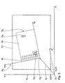
- the position of the camera 28 is in Fig. 3 indicated by the associated receiving area 34.
- a first object O 1 and a second object O 2 are arranged in the receiving area 34.
- the camera 28 picks up a reference image P 0 with the objects O 1 , O 2 .
- the travel unit 30 stores the coordinates x 1 (0), y 1 (0) of the stage 12 in the first coordinate system K 1 .
- the stage 12 is moved relative to the camera 28 by means of the x-drive motor 14 and the y-drive motor 16 in the xy plane in a different calibration position S 1 from the reference position S 0 .
- the object O 1 is still in the calibration position S 1 in the receiving area 34, whereas the object O 2 was moved out of the receiving area 34 by the method of the stage 12.
- the calibration position S 1 of the stage 12 relative to the camera 28 is in Fig. 4 illustrated.
- a calibration image P 1 is recorded by means of the camera 28, on which the first object O 1 is located.
- the traversing unit 30 stores the coordinates x 1 (1) for the calibration position S 1 , y 1 (1) of the stage 12 in the first coordinate system K 1 .
- the coordinates x 1 (1), y 1 (1) in the calibration position S 1 are determined in a simple manner on the basis of the executed number of steps of the x-drive motor 14 in the x-direction and the y-drive motor 16 in the y-direction.
- the registration unit 32 registers the calibration image P 1 with the reference image P 0 based on the object O 1 , which is located both in the reference image P 0 and in the calibration image P 1 .
- the registration takes place by means of a similarity measure, which characterizes the equality of the reference image P 0 and the calibration image P 1 .
- the similarity measure can be optimized by means of known registration methods. Area-based or feature-based registration methods can be used as the registration method. Due to the fact that the registration method evaluates the intensities in the individual pixels 35, the registration of the calibration image P 1 with the reference image P 0 takes place with subpixel accuracy. Subpixel accurate means that an object displacement distance ⁇ x 2 (1), ⁇ y 2 (1) can be determined with a smaller resolution than the discrete pixel coordinates. Registering the calibration image P 1 thus provides the object displacement distance ⁇ x 2 (1), ⁇ y 2 (1) in the second coordinate system K 2 .
- equation (9) the translation vector t 1 is eliminated since equation (9) contains coordinate differences, ie relative and not absolute coordinates.
- an object displacement distance ⁇ x 2 (n), ⁇ y 2 (n) is determined for each calibration image P n.
- an object displacement distance ⁇ x 2 (n), ⁇ y 2 (n) is determined.
- the optimization method implemented in the calibration unit 33 is used, which minimizes a quality functional, such as the quadratic error.
- the optimization method provides the coordinate transformation matrix A.
- a slide 19 can easily be automatically scanned and digitized. Due to the exact calibration, the assembly of the images of the slide 19 can take place without registration of these images.
- the exact calibration can automate and objectify the screening of cervical smears.
- the calibration ensures that no carcinoma cells are found on two images simultaneously and that no carcinoma cells are missed.
- carcinoma cells located at edges of images are neatly joined together.
- the slide 19 is first scanned in a low resolution.
- a defined number of leukocytes are automatically detected with image processing methods.
- the leucocytes are individually approached, focused and recorded in a subsequent step in a higher resolution in order to determine the exact type of the individual leukocytes with the aid of the higher resolution.
- Calibration ensures that no leucocytes are scanned or missed twice during low-resolution imaging.
- the calibration ensures that the individual leucocytes can be viewed and examined in the current field of vision.
- the calibration ensures that each erythrocyte can be examined and safely approached in a higher resolution.
Landscapes
- Engineering & Computer Science (AREA)
- Computer Vision & Pattern Recognition (AREA)
- Physics & Mathematics (AREA)
- General Physics & Mathematics (AREA)
- Theoretical Computer Science (AREA)
- Length Measuring Devices By Optical Means (AREA)
- Microscoopes, Condenser (AREA)
Abstract
Description
- Die Erfindung betrifft ein Verfahren zum Kalibrieren eines Bühne-Kamera-Systems. Ferner betrifft die Erfindung ein Bühne-Kamera-System für ein Mikroskop.
- Die computerassistierte Mikroskopie beschäftigt sich mit der Aufnahme und Analyse von biologischen Proben. Beispiele hierfür sind die automatische Untersuchung von Zervix-Zellen und die automatische Erstellung von Differentialblutbildern. Voll automatisierte Mikroskope steuern mit einer Steuereinrichtung alle mechanischen und elektronischen Komponenten des Mikroskops, so dass präparierte Objektträger vollständig autonom gescannt und untersucht werden können.
- Das Kalibrieren der automatisierten Mikroskope erfolgt manuell mittels eines Kalibrierobjektträgers. Der Kalibrierobjektträger wird auf einer verfahrbaren Bühne des Mikroskops angeordnet. Von einer markanten Stelle des Kalibrierobjektträgers wird ein Bild aufgenommen. Die Position der markanten Stelle in dem Bild wird manuell, beispielsweise mit einem Mauszeiger, bestimmt. Daraufhin wird die Bühne mit dem Kalibrierobjektträger um eine definierte Verfahrstrecke verfahren. Es wird nun ein weiteres Bild aufgenommen. Die Position der markanten Stelle in diesem Bild wird erneut manuell bestimmt. Aus der Verfahrstrecke der Bühne und den manuell bestimmten Positionen der markanten Stelle des Kalibrierobjektträgers kann grob ermittelt werden, welche Verfahrstrecke der Bühne welcher Objektverschiebestrecke in einem Bild der Kamera entspricht. Nachteilig bei einem derartigen manuellen Verfahren zum Kalibrieren des Bühne-Kamera-Systems des Mikroskops ist, dass der Kalibriervorgang zeitaufwändig ist. Darüber hinaus ist die manuelle Kalibrierung ungenau, wobei der Grad der Ungenauigkeit variiert.
- Der Erfindung liegt daher die Aufgabe zugrunde, ein Verfahren zum Kalibrieren eines Bühne-Kamera-Systems zu schaffen, dass schnell und genau ist.
- Diese Aufgabe wird erfindungsgemäß durch ein Verfahren mit den Merkmalen des Anspruchs 1 gelöst. Erfindungsgemäß wurde erkannt, dass durch das Registrieren eines Kalibrierbildes mit einem Referenzbild anhand mindestens eines beliebigen Objektes die Objektverschiebestrecke sehr genau ermittelbar und das Kalibrieren voll automatisierbar ist. Nach dem Aufnehmen des Referenzbildes in einer beliebigen Referenzstellung wird das Bühne-Kamera-System mittels des mindestens einen elektrischen Antriebsmotor in die Kalibrierstellung verfahren. Die Kalibrierstellung unterscheidet sich von der Referenzstellung. In der Kalibrierstellung muss zumindest ein Teil des mindestens einen Objektes, das in dem Referenzbild aufgenommen wurde, sich in dem Aufnahmebereich der Kamera befinden, so dass dieser Teil in dem Kalibrierbild aufgenommen werden kann. Die Verfahrstrecke der Bühne relativ zu der Kamera ist einfach ermittelbar, da das Verfahren mittels des mindestens einen Antriebsmotors gesteuert oder geregelt erfolgt, so dass alle erforderlichen Informationen zum Ermitteln der Verfahrstrecke in einer elektronischen Steuereinrichtung vorliegen. Die Verfahrstrecke wird relativ zu dem ersten Koordinatensystem ermittelt, relativ zu dem auch die Bühne verfahren wird. Nach dem Aufnehmen des Kalibrierbildes wird dieses mit dem Referenzbild registriert. Das Registrieren erfolgt anhand des mindestens einen Objektes, das sich sowohl in dem Referenzbild als auch - zumindest teilweise - in dem Kalibrierbild finden lässt. Zum Registrieren des Kalibrierbildes sind flächenbasierte oder merkmalsbasierte Registrierverfahren einsetzbar, wie beispielsweise Korrelationsverfahren, mathematische Schätzer oder der sogenannte Harris-Comer-Detector. Das Registrieren des Kalibrierbildes mit dem Referenzbild liefert unmittelbar die Objektverschiebestrecke, um die das mindestens eine Objekt beim Verfahren der Bühne relativ zu der Kamera in dem Kalibrierbild relativ zu dem Referenzbild verschoben wurde. Die Objektverschiebestrecke wird relativ zu dem zweiten Koordinatensystem ermittelt, relativ zu dem auch das mindestens eine Objekt in den Bildern der Kamera verschoben wird. Aus der Verfahrstrecke und der Objektverschiebestrecke lässt sich ein Kalibriermaß ermitteln, das angibt, welche Verfahrstrecke in dem ersten Koordinatensystem welcher Objektverschiebestrecke in dem zweiten Koordinatensystem entspricht. Das erfindungsgemäße Verfahren ermöglicht eine vollautomatisierte, schnelle und genaue Kalibrierung des Bühne-Kamera-Systems.
- Eine Weiterbildung nach Anspruch 2 stellt ein schnelles Kalibrieren eines zweidimensional verfahrbaren Bühne-Kamera-Systems sicher, da bereits bei einem einmaligen Verfahren des Bühne-Kamera-Systems ein Kalibrieren in einer x-Richtung und einer y-Richtung möglich ist. Vorzugsweise wird das Bühne-Kamera-System zufallsgesteuert in einem definierten Bereich verfahren.
- Ein Ermitteln der Verfahrstrecke nach Anspruch 3 ist einfach, wenn der mindestens eine elektrische Antriebsmotor als Schrittmotor ausgebildet ist.
- Eine Weiterbildung nach Anspruch 4 ist besonders genau. Subpixelgenau bedeutet, dass das Kalibrierbild mit dem Referenzbild mit einer Genauigkeit von Pixelbruchteilen der Auflösung der Kamera registrierbar ist. Die Objektverschiebestrecke kann somit mit einer höheren Genauigkeit als der Auflösegenauigkeit der Kamera ermittelt werden. Dies ist deswegen möglich, da subpixelgenaue Registrierverfahren die Intensitätsverteilungen in den Pixeln in dem Referenzbild und dem Kalibrierbild auswerten. Dies ist insbesondere dann vorteilhaft, wenn die Bühne relativ zu der Kamera mittels des mindestens einen elektrischen Antriebsmotors subpixelgenau positionierbar ist. Die bereits genannten flächenbasierten und merkmalsbasierten Registrierverfahren ermöglichen ein subpixelgenaues Registrieren. Als subpixelgenaues Registrierverfahren kann beispielsweise das Verfahren von Foroosh et al. verwendet werden, das in der Veröffentlichung "Extension of Phase Correlation to Subpixel Registration" (IEEE Transactions on Image Processing, Vol. 11, No. 3, März 2002) beschrieben ist. Bei diesem Verfahren wird davon ausgegangen, dass der Korrelationspeak bei im Subpixelbereich verschobenen Bildern, nicht in einem Pixel konzentriert ist, sondern in der direkten Nachbarschaft zum Hauptpeak noch Nebenpeaks existieren. Aus der Höhe der einzelnen Peaks lässt sich auf die subpixelgenaue Lage der Bilder schließen.
- Ein Verfahren des Bühne-Kamera-Systems nach Anspruch 5 ermöglicht ein zuverlässiges Kalibrieren, da Fehler bei dem Ermitteln der Verfahrstrecke oder der Objektverschiebestrecke erkennbar sind.
- Eine Weiterbildung nach Anspruch 6 ermöglicht größere Verfahrstrecken in unterschiedlichen Richtungen. Dies erhöht die Zuverlässigkeit der Kalibrierung.
- Ein Ermitteln des Kalibriermaßes nach Anspruch 7 erhöht die Genauigkeit der Kalibrierung. Das Kalibriermaß wird durch das Lösen eines Gleichungssystems bestimmt. Werden mehrere Kalibrierbilder aufgenommen und dementsprechend mehrere Objektverschiebestrecken ermittelt, so ist das Gleichungssystem überbestimmt. Durch ein Optimierungsverfahren, das ein Gütefunktional, wie beispielsweise das minimale Fehlerquadrat, minimiert, kann das überbestimmte Gleichungssystem optimal gelöst werden. Vorzugsweise werden lineare Optimierungsverfahren eingesetzt, wie beispielsweise der Random-Sample-Consensus-Algorithmus (RANSAC), der Maximum-Likelihood-Estimation-Sample-Consensus-Algorithmus (MLESAC), der Minimum-Unbiased-Scale-Estimator (MUSE), der M-Estimator-Sample-Consensus-Algorithmus (MSAC) oder der Least-Mean-Squares-Algorithmus (LMS).
- Ein Optimierungsverfahren nach Anspruch 8 ist robust und genau. Der Minimum-Unbiased-Scale-Estimator ist in der Veröffentlichung von James V. Miller und Charles V. Steward "MUSE: Robust Surface Fitting using Unbiased Scale Estimates" (1996 IEEE Computer Society Conference on Computer Vision and Pattern Recognition, 1996, p. 300) beschrieben.
- Ein Kalibriermaß nach Anspruch 9 ermöglicht die Berücksichtigung von einer Skalierung zwischen den Koordinatensystemen sowie von einer Rotation der Koordinatensysteme zueinander.
- Der Erfindung liegt ferner die Aufgabe zugrunde, ein Bühne-Kamera-System für ein Mikroskop bereitzustellen, das schnell und genau kalibrierbar ist.
- Diese Aufgabe wird erfindungsgemäß durch ein Bühne-Kamera-System mit den Merkmalen des Anspruchs 10 gelöst. Die Vorteile des erfindungsgemäßen Bühne-Kamera-Systems entsprechen den bereits beschriebenen Vorteilen des erfindungsgemäßen Verfahrens.
- Eine Weiterbildung nach Anspruch 11 ermöglicht ein einfaches Ermitteln der Verfahrstrecke. Darüber hinaus ist die Bühne relativ zu der Kamera in einfacher Weise subpixelgenau positionierbar.
- Eine Registrier-Einheit nach Anspruch 12 ermöglicht ein genaues Kalibrieren des Bühne-Kamera-Systems. Dies ist insbesondere dann vorteilhaft, wenn die Bühne relativ zu der Kamera subpixelgenau positionierbar ist.
- Eine Kalibrier-Einheit nach Anspruch 13 ermöglicht ein exaktes und robustes Kalibrieren des Bühne-Kamera-Systems.
- Ein Mikroskop nach Anspruch 14 ermöglicht das vollständige Automatisieren einer Vielzahl von medizinischen Untersuchungen. Derartige Untersuchungen sind beispielsweise das Screening von Zervix-Abstrichen, die automatische Erstellung von Differentialblutbildern und die Untersuchung von Erythrozyten bei Malaria-Untersuchungen.
- Weitere Merkmale und Vorteile der Erfindung ergeben sich aus der Beschreibung eines Ausführungsbeispieles anhand der Zeichnung. Es zeigen:
- Fig. 1
- eine schematische Darstellung eines Mikroskops mit einem Bühne-Kamera-System,
- Fig. 2
- eine schematische Darstellung einer elektronischen Steuerein- richtung des Bühne-Kamera-Systems in
Fig. 1 , - Fig. 3
- eine schematische Darstellung des Bühne-Kamera-Systems in einer Referenzstellung, und
- Fig. 4
- eine schematische Darstellung des Bühne-Kamera-Systems in einer Kalibrierstellung.
-
Fig. 1 zeigt ein Mikroskop 1, das als Digital-Mikroskop ausgebildet und in der computerassistierten Mikroskopie einsetzbar ist. Das Mikroskop 1 weist ein Stativ 2 mit einem Stativunterteil 3, einer Stativsäule 4 und einem Stativoberteil 5 auf. Das Stativunterteil 3 ist fußartig ausgebildet und dient zum sicheren Abstellen des Mikroskops 1 auf einer Abstellfläche 6. In das Stativunterteil 3 ist eine Durchlicht-Beleuchtungseinrichtung 7 integriert. Die Durchlicht-Beleuchtungseinrichtung 7 umfasst eine in dem Stativunterteil 3 integrierte Durchlicht-Beleuchtungsöffnung 8 und eine seitlich an dem Stativunterteil 3 angeordnete Durchlicht-Beleuchtungsquelle 9. - Die Stativsäule 4 verläuft im Wesentlichen senkrecht zu dem Stativunterteil 3 und dem Stativoberteil 5. Das Stativunterteil 3, die Stativsäule 4 und das Stativoberteil 5 sind im Querschnitt U-förmig zueinander angeordnet und begrenzen im Wesentlichen einen Mikroskopierraum 10.
- In dem Mikroskopierraum 10 ist an der Stativsäule 4 ein Kreuzschlitten 11 mit einer Bühne 12 angeordnet. Die Bühne 12 ist auf einem x-Schlitten 13 fest angeordnet. Der x-Schlitten 13 ist mittels eines elektrischen x-Antriebsmotors 14 in einer x-Richtung auf einem y-Schlitten 15 verfahrbar. Der y-Schlitten 15 ist entsprechend mit einem elektrischen y-Antriebsmotor 16 in einer y-Richtung auf einem z-Schlitten 17 verfahrbar. Der z-Schlitten 17 ist mittels eines elektrischen z-Antriebsmotors 18 in einer z-Richtung an der dem Mikroskopierraum 10 zugewandten Seite der Stativsäule 4 verfahrbar. Die Antriebsmotoren 14, 16, 18 sind als Schrittmotoren ausgebildet. Auf der Bühne 12 ist ein Objektträger 19 mit zu untersuchenden Objekten O1, O2 angeordnet.
- An einer dem Mikroskopierraum 10 zugewandten Seite des Stativoberteils 5 ist ein Objektivrevolver 20 mit mehreren Objektiven 21 drehbar angeordnet. In das Stativoberteil 5 ist eine Auflicht-Beleuchtungseinrichtung 22 integriert. Die Auflicht-Beleuchtungseinrichtung 22 weist eine in das Stativoberteil 5 integrierte und nicht näher dargestellte Auflicht-Beleuchtungsöffnung und eine seitlich an dem Stativoberteil 5 angeordnete Auflicht-Beleuchtungsquelle 23 auf.
- An einer dem Objektivrevolver 20 gegenüberliegenden Seite des Stativoberteils 5 ist ein Strahlenteiler 24 mit einem Tubusausgang 25 und einem Kameraausgang 26 angeordnet. An dem Tubusausgang 25 ist ein Tubus 27 befestigt. Entsprechend ist an dem Kameraausgang 26 eine als Digital-Kamera ausgebildete Kamera 28 befestigt.
- Die Antriebsmotoren 14, 16, 18 und die Kamera 28 sind mit einer elektronischen Steuereinrichtung 29 verbunden. Die Steuereinrichtung 29 dient zum Ansteuern der Antriebsmotoren 14, 16, 18, der Beleuchtungseinrichtungen 7, 22, des Objektivrevolvers 20 und der Kamera 28.
- Die mittels des x-Antriebsmotors 14 und des y-Antriebsmotors 16 in einer x-y-Ebene verfahrbare Bühne 12, die Kamera 28 und die elektronische Steuereinrichtung 29 bilden ein zu kalibrierendes Bühne-Kamera-System. Zum Kalibrieren weist die Steuereinrichtung 29 eine Verfahr-Einheit 30, eine Bildaufnahme-Einheit 31, eine Registrier-Einheit 32 und eine Kalibrier-Einheit 33 auf.
- Die Verfahr-Einheit 30 dient zum Verfahren der Bühne 12 relativ zu der Kamera 28 in einem ersten Koordinatensystem K1. Das erste Koordinatensystem K1 ist relativ zu dem Stativ 2 und der Kamera 28 ortsfest. Die x-Achse des ersten Koordinatensystems K1 wird mit x1 bezeichnet und verläuft parallel zu der x-Richtung. Die y-Achse des ersten Koordinatensystems K1 wird mit y1 bezeichnet und verläuft parallel zu der y-Richtung.
- Die Bildaufnahme-Einheit 31 dient zum Ansteuern der Kamera 28 zum Aufnehmen von digitalen Bildern und zum Auswerten von diesen Bildern. Das Aufnehmen und Auswerten der Bilder erfolgt in einem zweiten Koordinatensystem K2, das relativ zu einem Aufnahmebereich 34 der Kamera 28 ortsfest ist.
- Das zweite Koordinatensystem K2 ist relativ zu dem ersten Koordinatensystem K1 um einen Winkel ϕ gedreht. Ein Ursprung U1 des ersten Koordinatensystems K1 und ein Ursprung U2 des zweiten Koordinatensystems K2 sind um einen Translationsvektor t1 bezogen auf das erste Koordinatensystem K1 gegeneinander verschoben. Der Translationsvektor t1 beschreibt somit die Lage des zweiten Koordinatensystems K2 im ersten Koordinatensystem K1. Die x-Achse des zweiten Koordinatensystems K2 wird mit X2 bezeichnet. Entsprechend wird die y-Achse des zweiten Koordinatensystems K2 mit y2 bezeichnet.
- Der Aufnahmebereich 34 der Kamera 28 ist in Pixel 35 unterteilt, die die Auflösung der Kamera 28 charakterisieren. Dementsprechend weist das zweite Koordinatensystem K2 diskrete Pixelkoordinaten auf.
- Die Registrier-Einheit 32 dient zum Registrieren von mit der Kamera 28 aufgenommenen Bildern. In der Registrier-Einheit 32 ist ein Registrierverfahren implementiert, das ein subpixelgenaues Registrieren der Bilder ermöglicht.
- Die Kalibrier-Einheit 33 dient zum Ermitteln einer Koordinatentransformationsmatrix A zwischen dem ersten Koordinatensystem K1 und dem zweiten Koordinatensystem K2. Die Koordinatentransformationsmatrix A stellt ein Kalibriermaß dar. In die Kalibrier-Einheit 33 ist ein lineares Optimierungsverfahren zur Minimierung eines Gütefunktionals implementiert.
- Nachfolgend wird das erfindungsgemäße Verfahren zum Kalibrieren des Bühne-Kamera-Systems genauer beschrieben. In
Fig. 3 ist die Bühne 12 relativ zu der Kamera 28 in einer beliebigen Referenzstellung S0 angeordnet. Die Stellung der Kamera 28 ist inFig. 3 durch den zugehörigen Aufnahmebereich 34 angedeutet. Auf der Bühne 12 ist in dem Aufnahmebereich 34 ein erstes Objekt O1 und ein zweites Objekt O2 angeordnet. Die Kamera 28 nimmt in der Referenzstellung S0 ein Referenzbild P0 mit den Objekten O1, O2 auf. Zu der Referenzstellung S0 speichert die Verfahr-Einheit 30 die Koordinaten x1(0), y1(0) der Bühne 12 in dem ersten Koordinatensystem K1. - Anschließend wird die Bühne 12 relativ zu der Kamera 28 mittels des x-Antriebsmotors 14 und des y-Antriebsmotors 16 in der x-y-Ebene in eine von der Referenzstellung S0 unterschiedliche Kalibrierstellung S1 verfahren. Das Objekt O1 befindet sich in der Kalibrierstellung S1 weiterhin in dem Aufnahmebereich 34, wohingegen das Objekt O2 durch das Verfahren der Bühne 12 aus dem Aufnahmebereich 34 herausbewegt wurde. Die Kalibrierstellung S1 der Bühne 12 relativ zu der Kamera 28 ist in
Fig. 4 veranschaulicht. - In der Kalibrierstellung S1 wird mittels der Kamera 28 ein Kalibrierbild P1 aufgenommen, auf dem sich das erste Objekt O1 befindet. Die Verfahr-Einheit 30 speichert zu der Kalibrierstellung S1 die Koordinaten x1(1), y1(1) der Bühne 12 in dem ersten Koordinatensystem K1. Die Koordinaten x1(1), y1(1) in der Kalibrierstellung S1 werden in einfacher Weise anhand der ausgeführten Schrittanzahl des x-Antriebsmotors 14 in x-Richtung und des y-Antriebsmotors 16 in y-Richtung ermittelt. Die Verfahr-Einheit 30 ermittelt eine Verfahrstrecke Δx1(1), Dy1(1) der Bühne 12 von der Referenzstellung S0 in die Kalibrierstellung S1 in dem ersten Koordinatensystem K1 nach folgenden Gleichungen:


- Die Registrier-Einheit 32 registriert das Kalibrierbild P1 mit dem Referenzbild P0 anhand des Objektes O1, das sich sowohl in dem Referenzbild P0 als auch in dem Kalibrierbild P1 befindet. Das Registrieren erfolgt mittels eines Ähnlichkeitsmaßes, das die Gleichheit des Referenzbildes P0 und des Kalibrierbildes P1 charakterisiert. Das Ähnlichkeitsmaß kann mittels bekannter Registrierverfahren optimiert werden. Als Registrierverfahren können flächenbasierte oder merkmalsbasierte Registrierverfahren eingesetzt werden. Dadurch, dass das Registrierverfahren die Intensitäten in den einzelnen Pixeln 35 auswertet, erfolgt die Registrierung des Kalibrierbildes P1 mit dem Referenzbild P0 subpixelgenau. Subpixelgenau bedeutet, dass eine Objektverschiebestrecke Δx2(1), Δy2(1) mit einer kleineren Auflösung als den diskreten Pixelkoordinaten ermittelbar ist. Das Registrieren des Kalibrierbildes P1 liefert somit die Objektverschiebestrecke Δx2(1), Δy2(1) in dem zweiten Koordinatensystem K2.
- Das Ermitteln der Koordinatetransformationsmatrix A als Kalibriermaß erfolgt mittels der Kalibrier-Einheit 33. Für die Berechnung der Koordinatentransformationsmatrix A wird davon ausgegangen, dass die Bühne 12 senkrecht zu der Kamera 28 steht. Eine Scherung wird vernachlässigt. Somit verlaufen die von den Koordinatensystem K1, K2 auf gespannten Ebenen parallel zueinander. Für eine zweidimensionale Ähnlichkeitstransformation gilt allgemein folgende Gleichung:

- In Gleichung (3) bezeichnen:


- Durch Differenzbildung von Gleichung (3) in zwei Punkten ergibt sich folgende Gleichung:

- In Gleichung (9) ist der Translationsvektor t1 eliminiert, da Gleichung (9) Koordinatendifferenzen, also relative und keine absolute Koordinaten enthält.


- Die Koordinatentransformationsmatrix A ergibt sich durch Multiplikation der Skalierungsmatrix S mit der Rotationsmatrix R unter Berücksichtigung, dass der Skalierungsfaktor in x-Richtung sx und der Skalierungsfaktor in y-Richtung sy gleich sind und somit durch einen richtungsunabhängigen Skalierungsfaktor s beschreibbar sind, zu:

- Wird in Gleichung (9) die Verfahrstrecke Δx1(1), Δy1(1) von der Referenzstellung S0 in die Kalibrierstellung S1 und die zugehörige Objektverschiebestrecke Δx2(1), Δy2(1) zwischen dem Referenzbild P0 und dem Kalibrierbild P1 eingesetzt, so ergibt sich ein lineares Gleichungssystem mit zwei Gleichungen und zwei Unbekannten s und ϕ. Dieses Gleichungssystem lässt sich analytisch lösen, wobei das Ergebnis die Koordinatentransformationsmatrix A ist. Absolute Koordinaten können mittels Gleichung (3) ermittelt werden.
- Um die Zuverlässigkeit der Berechnung der Koordinatentransformationsmatrix A zu erhöhen, können mittels der Antriebsmotoren 14, 16 mehrere Kalibrierstellungen Sn mit n=1 bis N angefahren werden, wobei in jeder Kalibrierstellung Sn mittels der Kamera 28 ein Kalibrierbild Pn mit n=1 bis N aufgenommen wird. Beim Anfahren der Kalibrierstellungen Sn ist zu beachten, dass zumindest ein Teil eines der Objekte O1, O2, die sich im Referenzbild P0 befinden, auch in jedem Kalibrierbild Pn befindet, so dass ein Registrieren der Kalibrierbilder Pn zu dem Referenzbild P0 möglich ist. Zu jeder Kalibrierstellung Sn wird eine Verfahrstrecke Δx1(n), Δy1(n) ermittelt. Entsprechend wird zu jedem Kalibrierbild Pn eine Objektverschiebestrecke Δx2(n), Δy2(n) ermittelt. Durch Einsetzen der Verfahrstrecken Δx1(n), Δy1(n) und der zugehörigen Objektverschiebestrecken Δx2(n), Δy2(n) in Gleichung (9) entsteht ein überbestimmtes Gleichungssystem. Zur Lösung dieses überbestimmten Gleichungssystems wird das in die Kalibrier-Einheit 33 implementierte Optimierungsverfahren eingesetzt, das ein Gütefunktional, wie beispielsweise den quadratischen Fehler, minimiert. Als Ergebnis liefert das Optimierungsverfahren die Koordinatentransformationsmatrix A.
- Durch das Kalibrieren der Koordinatensysteme K1, K2 ist eine subpixelgenaue Zuordnung zwischen den Pixelkoordinaten der Kamera 28 und der Position der Bühne 12 gegeben. Dies ermöglicht die Bühne 12 subpixelgenau zu verfahren und spezifische Punkte auf dem Objektträger 19 wiederholbar und zuverlässig anzufahren. Ein Ausrichtungsfehler der Kamera 28 wird ausgeglichen, da die Rotation des zweiten Koordinatensystems K2 zu dem ersten Koordinatensystem K1 in die Kalibrierung mit einbezogen ist. Die Kalibrierung ist voll automatisiert und kann mit beliebigen Objekten O1, O2 durchgeführt werden. Aufgrund des subpixelgenauen Registrierverfahrens und des Optimierungsverfahrens zur Ermittlung der Koordinatentransformationsmatrix A ist die Kalibrierung genau und robust. Die Aufnahme eines größeren Bereichs des Objektträgers 19 in mehreren Bildern sowie die Aufnahme in unterschiedlichen Auflösungsstufen sind nach erfolgter Kalibrierung kein Problem mehr.
- In der virtuellen Mikroskopie kann ein Objektträger 19 problemlos automatisch gescannt und digitalisiert werden. Durch die exakte Kalibrierung kann das Zusammensetzen der Bilder des Objektträgers 19 ohne eine Registrierung dieser Bilder erfolgen.
- Weiterhin kann durch die exakte Kalibrierung das Screening von Zervix-Abstrichen automatisiert und objektiviert werden. Die Kalibrierung stellt sicher, dass keine Karzinomzellen gleichzeitig auf zwei Bildern zu finden sind und dass keine Karzinomzellen übersehen werden. Darüber hinaus werden Karzinomzellen, die sich an Bildrändern befinden, sauber aneinander gefügt.
- Bei der automatischen Erstellung von Differentialblutbildern in der computerassistierten Mikroskopie wird der Objektträger 19 zunächst in einer niedrigen Auflösung gescannt. In den erhaltenen Bildern wird eine definierte Anzahl von Leukozyten mit Bildverarbeitungsverfahren automatisch detektiert. Mit der Information über die Position der Leukozyten auf dem Objektträger 19 werden die Leukozyten in einem nachfolgenden Schritt in einer höheren Auflösung erneut einzeln angefahren, fokussiert und aufgenommen, um mithilfe der höheren Auflösung den exakten Typ der einzelnen Leukozyten bestimmen zu können. Die Kalibrierung stellt bei der Aufnahme in niedriger Auflösung sicher, dass keine Leukozyten zweimal gescannt oder übersehen werden. Weiterhin stellt die Kalibrierung bei erneutem Anfahren der Leukozyten in einer höheren Auflösung sicher, dass die einzelnen Leukozyten im aktuellen Sichtfeld betrachtet und untersucht werden können.
- Bei der Untersuchung auf Malaria wird durch die Kalibrierung sichergestellt, dass jeder Erythrozyt untersucht und in einer höheren Auflösung sicher angefahren werden kann.
Claims (14)
- Verfahren zum Kalibrieren eines Bühne-Kamera-Systems, umfassend die Schritte:- Bereitstellen eines Bühne-Kamera-Systems (12, 14, 16, 28, 29) mit einer Bühne (12) und einer Kamera (28), wobei- - die Bühne (12) und die Kamera (28) relativ zueinander in einer Referenzstellung (S0) angeordnet sind, und- - auf der Bühne (12) in einem Aufnahmebereich (34) der Kamera (28) mindestens ein Objekt (O1, O2) angeordnet ist,- Aufnehmen eines Referenzbildes (P0) des mindestens einen Objektes (O1, O2) in der Referenzstellung (S0),- Verfahren des Bühne-Kamera-Systems (12, 14, 16, 28, 29) mittels mindestens eines elektrischen Antriebsmotors (14, 16) derart, dass die Bühne (12) und die Kamera (28) relativ zueinander in einer Kalibrierstellung (Sn) angeordnet sind, wobei- - sich die Kalibrierstellung (Sn) von der Referenzstellung (S0) unterscheidet, und- - sich zumindest ein Teil des mindestens einen Objektes (O1, O2) in der Kalibrierstellung (Sn) in dem Aufnahmebereich (34) der Kamera (28) befindet,- Aufnehmen eines Kalibrierbildes (Pn) des mindestens einen Objektes (O1, O2) in der Kalibrierstellung (Sn),- Ermitteln einer Verfahrstrecke (Δx1 (n), Δy1 (n)) von der Referenzstellung (S0) in die Kalibrierstellung (Sn) in einem ersten Koordinatensystem (K1) mittels einer elektronischen Steuereinrichtung (29),- Registrieren des Kalibrierbildes (Pn) mit dem Referenzbild (P0) anhand des mindestens einen Objektes (O1, O2) mittels der elektronischen Steuereinrichtung (29),- Ermitteln einer Objektverschiebestrecke (Δx2 (n), Δy2 (n)) in einem zweiten Koordinatensystem (K2) anhand des registrierten Kalibrierbildes (Pn) mittels der elektronischen Steuereinrichtung (29), und- Ermitteln eines Kalibriermaßes (A) aus der Verfahrstrecke (Δx1 (n), Δy1 (n)) und der Objektverschiebestrecke (Δx2 (n), Δy2 (n)) zum Kalibrieren der Koordinatensysteme (K1, K2) mittels der elektronischen Steuereinrichtung (29).
- Verfahren nach Anspruch 1, dadurch gekennzeichnet, dass das Verfahren in einer x-y-Ebene erfolgt und die Verfahrstrecke (Δx1 (n), Δy1 (n)) in dem ersten Koordinatensystem (K1) eine x-Komponente (Δx1(n)) und eine y-Komponente (Δy1(n)) aufweist.
- Verfahren nach Anspruch 1 oder 2, dadurch gekennzeichnet, dass die Verfahrstrecke (ΔX1 (n), Δy1 (n)) aus einer Schrittanzahl des mindestens einen elektrischen Antriebsmotors (14, 16) ermittelt wird.
- Verfahren nach einem der Ansprüche 1 bis 3, dadurch gekennzeichnet, dass das Registrieren des Kalibrierbildes (Pn) subpixelgenau erfolgt.
- Verfahren nach einem der Ansprüche 1 bis 4, dadurch gekennzeichnet, dass das Bühne-Kamera-System (12, 14, 16, 28, 29) in mehrere unterschiedliche Kalibrierstellungen (Sn) verfahren wird, wobei in jeder Kalibrierstellung (Sn) ein Kalibrierbild (Pn) aufgenommen und eine Verfahrstrecke (Δx1 (n), Δy1 (n)) sowie eine zugehörige Objektverschiebestrecke (Δx2 (n), Δy2 (n)) ermittelt wird.
- Verfahren nach Anspruch 5, dadurch gekennzeichnet, dass das Referenzbild (P0) mehrere Objekte (O1, O2) und jedes Kalibrierbild (Pn) zumindest einen Teil eines der Objekte (O1, O2) enthält, wobei das Registrieren der Kalibrierbilder (Pn) zumindest teilweise anhand unterschiedlicher Objekte (O1, O2) erfolgt.
- Verfahren nach Anspruch 5 oder 6, dadurch gekennzeichnet, dass das Kalibriermaß (A) mittels eines Optimierungsverfahrens ermittelt wird, wobei das Optimierungsverfahren ein Gütefunktional minimiert.
- Verfahren nach Anspruch 7, dadurch gekennzeichnet, dass das Optimierungsverfahren als Minimum-Unbiased-Scale-Estimator ausgebildet ist.
- Verfahren nach einem der Ansprüche 1 bis 8, dadurch gekennzeichnet, dass das Kalibriermaß (A) eine Koordinatentransformationsmatrix zwischen dem ersten und zweiten Koordinatensystem (K1, K2) ist.
- Bühne-Kamera-System mit- einer Kamera (28) zur Aufnahme von Bildern (P0, Pn),- einer Bühne (12), wobei- - die Bühne (12) und die Kamera (28) relativ zueinander verfahrbar sind, und- - auf der Bühne (12) in einem Aufnahmebereich (34) der Kamera (28) mindestens ein Objekt (O1, O2) positionierbar ist,- mindestens einem elektrischen Antriebsmotor (14, 16) zum relativen Verfahren der Bühne (12) und der Kamera (28) zueinander,- einer elektronischen Steuereinrichtung (29), die- - eine Verfahr-Einheit (30) aufweist, mittels der das Verfahren von einer Referenzstellung (S0) in eine Kalibrierstellung (Sn) steuerbar und eine Verfahrstrecke (Δx1 (n), Δy1 (n)) in einem ersten Koordinatensystem (K1) ermittelbar ist,- - eine Bildaufnahme-Einheit (31) aufweist, mittels der das Aufnehmen eines Referenzbildes (P0) des mindestens einen Objektes (O1, O2) in der Referenzstellung (S0) und eines Kalibrierbildes (Pn) des mindestens einen Objektes (O1, O2) in der Kalibrierstellung (Sn) steuerbar ist,- - eine Registrier-Einheit (32) aufweist, mittels der das Kalibrierbild (Pn) mit dem Referenzbild (P0) registrierbar und eine Objektverschiebestrecke (Δx2 (n), Δy2 (n)) in einem zweiten Koordinatensystem (K2) ermittelbar ist, und- - eine Kalibrier-Einheit (33) aufweist, mittels der ein Kalibriermaß (A) aus der Verfahrstrecke (Δx1 (n), Δy1 (n)) und der Objektverschiebestrecke (Δx2 (n), Δy2 (n)) zum Kalibrieren der Koordinatensysteme (K1, K2) ermittelbar ist.
- Bühne-Kamera-System nach Anspruch 10, dadurch gekennzeichnet, dass der mindestens eine elektrische Antriebsmotor (14, 16) als Schrittmotor ausgebildet ist.
- Bühne-Kamera-System nach Anspruch 10 oder 11, dadurch gekennzeichnet, dass die Registrier-Einheit (32) derart ausgebildet ist, dass das Kalibrierbild (Pn) subpixelgenau mit dem Referenzbild (P0) registrierbar ist.
- Bühne-Kamera-System nach einem der Ansprüche 10 bis 12, dadurch gekennzeichnet, dass die Kalibrier-Einheit (33) derart ausgebildet ist, dass das Kalibriermaß (A) mittels eine Optimierungsverfahrens zur Minimierung eines Gütefunktionals ermittelbar ist.
- Mikroskop mit einem Bühne-Kamera-System (12, 14, 16, 28, 29) nach einem der Ansprüche 10 bis 13.
Applications Claiming Priority (1)
| Application Number | Priority Date | Filing Date | Title |
|---|---|---|---|
| DE102008014030.9A DE102008014030B4 (de) | 2008-03-12 | 2008-03-12 | Verfahren zum Kalibrieren eines Bühne-Kamera-Systems sowie Bühne-Kamera-System und Mikroskop mit derartigem Bühne-Kamera-System |
Publications (2)
| Publication Number | Publication Date |
|---|---|
| EP2101297A1 true EP2101297A1 (de) | 2009-09-16 |
| EP2101297B1 EP2101297B1 (de) | 2013-05-15 |
Family
ID=40902152
Family Applications (1)
| Application Number | Title | Priority Date | Filing Date |
|---|---|---|---|
| EP09003241.8A Not-in-force EP2101297B1 (de) | 2008-03-12 | 2009-03-06 | Verfahren zum Kalibrieren eines Bühne-Kamera-Systems eines Mikroskops |
Country Status (3)
| Country | Link |
|---|---|
| US (1) | US8532950B2 (de) |
| EP (1) | EP2101297B1 (de) |
| DE (1) | DE102008014030B4 (de) |
Cited By (1)
| Publication number | Priority date | Publication date | Assignee | Title |
|---|---|---|---|---|
| CN114747198A (zh) * | 2019-12-10 | 2022-07-12 | 深圳迈瑞生物医疗电子股份有限公司 | 细胞图像分析装置及相机安装平行性校验方法 |
Families Citing this family (16)
| Publication number | Priority date | Publication date | Assignee | Title |
|---|---|---|---|---|
| DE102009054703A1 (de) * | 2009-12-15 | 2011-06-16 | Carl Zeiss Imaging Solutions Gmbh | Kalibrierverfahren für ein Mikroskop und Mikroskop mit einer Kalibriereinheit |
| US9135707B2 (en) * | 2010-06-28 | 2015-09-15 | Koninklijke Philips N.V. | Real-time quality control of EM calibration |
| DE102012223763B3 (de) | 2012-12-19 | 2013-08-22 | Leica Microsystems (Schweiz) Ag | Verfahren zur Selbstkalibrierung eines Mikroskopgeräts |
| TWI554100B (zh) * | 2012-12-27 | 2016-10-11 | Metal Ind Res &Development Ct | Correction sheet design for correcting a plurality of image capturing apparatuses and correction methods of a plurality of image capturing apparatuses |
| US10380764B2 (en) * | 2013-12-18 | 2019-08-13 | Cognex Corporation | System and method for performing vision system planar hand-eye calibration from straight line features |
| USD770523S1 (en) * | 2014-01-29 | 2016-11-01 | Samsung Electronics Co., Ltd. | Display screen or portion thereof with icon |
| JP6562626B2 (ja) * | 2014-12-10 | 2019-08-21 | キヤノン株式会社 | 顕微鏡システム |
| JP6456149B2 (ja) * | 2015-01-13 | 2019-01-23 | 株式会社トプコン | 測量機器 |
| GB201507080D0 (en) * | 2015-04-27 | 2015-06-10 | Ipsum Ltd | Closures |
| JP6619217B2 (ja) * | 2015-11-26 | 2019-12-11 | オリンパス株式会社 | 顕微鏡システムとその制御方法 |
| CN108474719B (zh) * | 2015-12-17 | 2020-08-28 | 倍耐力轮胎股份公司 | 用于校准轮胎检查系统的光学工具的方法和设备 |
| US10284756B2 (en) | 2016-03-11 | 2019-05-07 | Bio-Rad Laboratories, Inc. | Camera assembly and system for mounting thereof |
| WO2018064660A1 (en) * | 2016-09-30 | 2018-04-05 | University Of Utah Research Foundation | Lensless imaging device |
| DE102018215491A1 (de) * | 2018-09-12 | 2020-03-12 | Robert Bosch Gmbh | Verfahren zur Kalibrierung eines Erfassungssystems |
| EP4083684B1 (de) * | 2021-04-29 | 2025-09-10 | PreciPoint GmbH | Verfahren zur optischen auswertung der betriebsgenauigkeit eines digitalen mikroskops, verfahren zur steuerung eines beweglichen tisches eines digitalen mikroskops und fotomaske zur optischen auswertung der betriebsgenauigkeit eines digitalen mikroskops |
| WO2023111198A1 (en) * | 2021-12-16 | 2023-06-22 | Enaiblers Ab | Systems and methods for calibrating an imaging system |
Citations (6)
| Publication number | Priority date | Publication date | Assignee | Title |
|---|---|---|---|---|
| US3986007A (en) * | 1975-08-20 | 1976-10-12 | The Bendix Corporation | Method and apparatus for calibrating mechanical-visual part manipulating system |
| WO2004034124A1 (de) * | 2002-10-02 | 2004-04-22 | Leica Microsystems Wetzlar Gmbh | Mikroskop mit korrektur und verfahren zur korrektur der durch temperaturänderung hervorgerufenen xyz-drift |
| US20040114218A1 (en) * | 2001-04-12 | 2004-06-17 | Adam Karlsson | Method in microscopy and a microscope, where subimages are recorded and puzzled in the same coordinate system to enable a precise positioning of the microscope stage |
| WO2005017597A1 (de) * | 2003-08-11 | 2005-02-24 | Leica Microsystems Cms Gmbh | Verfahren und system zur geräteunabhängigen bestimmung von koordinaten eines mittels eines mikroskops abgebildeten punktes |
| US20060034543A1 (en) * | 2004-08-16 | 2006-02-16 | Bacus James V | Method and apparatus of mechanical stage positioning in virtual microscopy image capture |
| US20070211243A1 (en) * | 2006-03-13 | 2007-09-13 | Clemex Technologies Inc. | System and method for automatic measurements and calibration of computerized magnifying instruments |
Family Cites Families (9)
| Publication number | Priority date | Publication date | Assignee | Title |
|---|---|---|---|---|
| DE3718066A1 (de) * | 1987-05-29 | 1988-12-08 | Zeiss Carl Fa | Verfahren zur mikroinjektion in zellen bzw. zum absaugen aus einzelnen zellen oder ganzer zellen aus zellkulturen |
| US5581487A (en) * | 1994-02-23 | 1996-12-03 | Science Applications International Corporation | Method and apparatus for microscopic screening of cytological samples |
| JP2000106121A (ja) * | 1998-07-29 | 2000-04-11 | Jeol Ltd | 電子顕微鏡あるいはその類似装置 |
| US20020149628A1 (en) * | 2000-12-22 | 2002-10-17 | Smith Jeffrey C. | Positioning an item in three dimensions via a graphical representation |
| US7177486B2 (en) * | 2002-04-08 | 2007-02-13 | Rensselaer Polytechnic Institute | Dual bootstrap iterative closest point method and algorithm for image registration |
| EP1548480A4 (de) * | 2002-09-06 | 2007-02-14 | Celestar Lexico Sciences Inc | Mikroskopbildverarbeitungssystem, mikroskopbildverarbeitungsverfahren, programm und aufzeichnungsmedium |
| DE102004029912A1 (de) * | 2004-06-16 | 2006-01-05 | Carl Zeiss Jena Gmbh | Programmgesteuertes Mikroskop und Verfahren zur externen Steuerung von Mikroskopen |
| DE102006034906A1 (de) * | 2006-07-28 | 2008-01-31 | Carl Zeiss Microimaging Gmbh | Laser-Scanning-Mikroskop und Verfahren zu seinem Betrieb |
| DE102006036172B4 (de) * | 2006-07-31 | 2018-11-22 | Carl Zeiss Microscopy Gmbh | Optische Anordnung zur sequentiellen Positionierung von Arbeitsfeldern auf einem Objekt |
-
2008
- 2008-03-12 DE DE102008014030.9A patent/DE102008014030B4/de not_active Expired - Fee Related
-
2009
- 2009-03-06 EP EP09003241.8A patent/EP2101297B1/de not_active Not-in-force
- 2009-03-12 US US12/402,783 patent/US8532950B2/en not_active Expired - Fee Related
Patent Citations (6)
| Publication number | Priority date | Publication date | Assignee | Title |
|---|---|---|---|---|
| US3986007A (en) * | 1975-08-20 | 1976-10-12 | The Bendix Corporation | Method and apparatus for calibrating mechanical-visual part manipulating system |
| US20040114218A1 (en) * | 2001-04-12 | 2004-06-17 | Adam Karlsson | Method in microscopy and a microscope, where subimages are recorded and puzzled in the same coordinate system to enable a precise positioning of the microscope stage |
| WO2004034124A1 (de) * | 2002-10-02 | 2004-04-22 | Leica Microsystems Wetzlar Gmbh | Mikroskop mit korrektur und verfahren zur korrektur der durch temperaturänderung hervorgerufenen xyz-drift |
| WO2005017597A1 (de) * | 2003-08-11 | 2005-02-24 | Leica Microsystems Cms Gmbh | Verfahren und system zur geräteunabhängigen bestimmung von koordinaten eines mittels eines mikroskops abgebildeten punktes |
| US20060034543A1 (en) * | 2004-08-16 | 2006-02-16 | Bacus James V | Method and apparatus of mechanical stage positioning in virtual microscopy image capture |
| US20070211243A1 (en) * | 2006-03-13 | 2007-09-13 | Clemex Technologies Inc. | System and method for automatic measurements and calibration of computerized magnifying instruments |
Non-Patent Citations (4)
| Title |
|---|
| AMMI M ET AL: "Flexible Microscope Calibration using Virtual Pattern for 3-D Telemicromanipulation", ROBOTICS AND AUTOMATION, 2005. PROCEEDINGS OF THE 2005 IEEE INTERNATIONAL CONFERENCE ON BARCELONA, SPAIN 18-22 APRIL 2005, PISCATAWAY, NJ, USA,IEEE, 18 April 2005 (2005-04-18), pages 3888 - 3893, XP010871523, ISBN: 978-0-7803-8914-4 * |
| FOROOSH ET AL.: "Extension of Phase Correlation to Subpixel Registration", IEEE TRANSACTIONS ON IMAGE PROCESSING, vol. 11, no. 3, March 2002 (2002-03-01) |
| JAMES V. MILLER; CHARLES V. STEWARD: "MUSE: Robust Surface Fitting using Unbiased Scale Estimates", 1996 IEEE COMPUTER SOCIETY CONFERENCE ON COMPUTER VISION AND PATTERN RECOGNITION, 1996, pages 300 |
| SETH HUTCHINSON ET AL: "A Tutorial on Visual Servo Control", IEEE TRANSACTIONS ON ROBOTICS AND AUTOMATION, IEEE INC, NEW YORK, US, vol. 12, no. 5, 1 October 1996 (1996-10-01), XP011053146, ISSN: 1042-296X * |
Cited By (2)
| Publication number | Priority date | Publication date | Assignee | Title |
|---|---|---|---|---|
| CN114747198A (zh) * | 2019-12-10 | 2022-07-12 | 深圳迈瑞生物医疗电子股份有限公司 | 细胞图像分析装置及相机安装平行性校验方法 |
| CN114747198B (zh) * | 2019-12-10 | 2024-04-02 | 深圳迈瑞生物医疗电子股份有限公司 | 细胞图像分析装置及相机安装平行性校验方法 |
Also Published As
| Publication number | Publication date |
|---|---|
| EP2101297B1 (de) | 2013-05-15 |
| DE102008014030A1 (de) | 2009-09-24 |
| US8532950B2 (en) | 2013-09-10 |
| US20100066838A1 (en) | 2010-03-18 |
| DE102008014030B4 (de) | 2017-01-26 |
Similar Documents
| Publication | Publication Date | Title |
|---|---|---|
| EP2101297B1 (de) | Verfahren zum Kalibrieren eines Bühne-Kamera-Systems eines Mikroskops | |
| DE102014206309B4 (de) | System und Verfahren zum Erhalten von Bildern mit Versatz zur Verwendung für verbesserte Kantenauflösung | |
| DE69213749T2 (de) | Verfahren und vorrichtung zur punktualmessung von raumkoordinaten | |
| DE102014109687B4 (de) | Positionsbestimmung eines Objekts im Strahlengang einer optischen Vorrichtung | |
| DE3313789A1 (de) | Selbsttaetige mikroskopische untersuchungseinrichtung und verfahren zur ermittlung und wiederfindung von objekten in einem bild | |
| EP2920577B1 (de) | Vorrichtung und verfahren zur mikroskopie einer vielzahl von proben | |
| DE69833835T2 (de) | Verfahren zur Bestimmung der Dicke eines optischen Prüfkörpers | |
| DE2720036C2 (de) | Doppel-Auflösungs-Bildanalysator | |
| EP2870500A1 (de) | Verfahren zur vorbereitung und durchführung der aufnahme von bildstapeln einer probe aus verschiedenen orientierungswinkeln | |
| DE3505331A1 (de) | Verfahren und geraet zur vermessung des bei der eindringhaertepruefung in einer probe hinterlassenen eindrucks | |
| DE102015108017A1 (de) | Verfahren und Untersuchungssystem zur Untersuchung und Bearbeitung einer mikroskopischen Probe | |
| DE102016107900A1 (de) | Verfahren und Vorrichtung zur Kantenermittlung eines Messobjekts in der optischen Messtechnik | |
| DE10336803A1 (de) | Verfahren und System zur geräteunabhängigen Bestimmung von Koordinaten eines mittels eines Mikroskops abgebildeten Punktes | |
| DE102005007533B4 (de) | Objektträgervorrichtung | |
| AT500499B1 (de) | Mittelpunktbestimmung von justiermarken | |
| DE10315592B4 (de) | Verfahren zum Ausführen von Interaktionen an sich räumlich und zeitlich verändernden mikroskopischen Objekten und System hierzu | |
| EP1548485B1 (de) | Verfahren zur Korrektur der Drift bei einem optischen Gerät | |
| DE102021111706B4 (de) | Verfahren, Messgerät und Computerprogramm | |
| DE112015006181T5 (de) | Ladungsträgerstrahlvorrichtung, Ausrichtungsverfahren für die L.adungsträgerstrahlvorrichtung, Ausrichtungsprogramm und Speichermedium | |
| DE102017223435B9 (de) | Verfahren zum Betrieb eines Mikroskops | |
| CH695958A5 (de) | Verfahren zur Einstellung einer Lage eines Messgegenstandes bei der Schichtdickenmessung mit Röntgenfluoreszenz. | |
| DE2635356A1 (de) | Rasterelektronenmikroskop zur kontrolle von objektstrukturen | |
| EP2383600A1 (de) | Verfahren, Vorrichtung und Computerprogrammprodukt zur Fokussierungsvorhersage | |
| DE102011101509C5 (de) | Verfahren zur optischen Vermessung einer Welle | |
| DE10359780B4 (de) | Verfahren zur optischen Bilderfassung |
Legal Events
| Date | Code | Title | Description |
|---|---|---|---|
| PUAI | Public reference made under article 153(3) epc to a published international application that has entered the european phase |
Free format text: ORIGINAL CODE: 0009012 |
|
| AK | Designated contracting states |
Kind code of ref document: A1 Designated state(s): AT BE BG CH CY CZ DE DK EE ES FI FR GB GR HR HU IE IS IT LI LT LU LV MC MK MT NL NO PL PT RO SE SI SK TR |
|
| AX | Request for extension of the european patent |
Extension state: AL BA RS |
|
| 17P | Request for examination filed |
Effective date: 20091202 |
|
| 17Q | First examination report despatched |
Effective date: 20100104 |
|
| AKX | Designation fees paid |
Designated state(s): AT BE BG CH CY CZ DE DK EE ES FI FR GB GR HR HU IE IS IT LI LT LU LV MC MK MT NL NO PL PT RO SE SI SK TR |
|
| GRAP | Despatch of communication of intention to grant a patent |
Free format text: ORIGINAL CODE: EPIDOSNIGR1 |
|
| GRAS | Grant fee paid |
Free format text: ORIGINAL CODE: EPIDOSNIGR3 |
|
| GRAA | (expected) grant |
Free format text: ORIGINAL CODE: 0009210 |
|
| AK | Designated contracting states |
Kind code of ref document: B1 Designated state(s): AT BE BG CH CY CZ DE DK EE ES FI FR GB GR HR HU IE IS IT LI LT LU LV MC MK MT NL NO PL PT RO SE SI SK TR |
|
| REG | Reference to a national code |
Ref country code: GB Ref legal event code: FG4D Free format text: NOT ENGLISH Ref country code: CH Ref legal event code: EP |
|
| REG | Reference to a national code |
Ref country code: AT Ref legal event code: REF Ref document number: 612481 Country of ref document: AT Kind code of ref document: T Effective date: 20130615 |
|
| REG | Reference to a national code |
Ref country code: IE Ref legal event code: FG4D Free format text: LANGUAGE OF EP DOCUMENT: GERMAN |
|
| REG | Reference to a national code |
Ref country code: DE Ref legal event code: R096 Ref document number: 502009007067 Country of ref document: DE Effective date: 20130711 |
|
| REG | Reference to a national code |
Ref country code: LT Ref legal event code: MG4D |
|
| REG | Reference to a national code |
Ref country code: NL Ref legal event code: VDEP Effective date: 20130515 |
|
| PG25 | Lapsed in a contracting state [announced via postgrant information from national office to epo] |
Ref country code: SE Free format text: LAPSE BECAUSE OF FAILURE TO SUBMIT A TRANSLATION OF THE DESCRIPTION OR TO PAY THE FEE WITHIN THE PRESCRIBED TIME-LIMIT Effective date: 20130515 Ref country code: LT Free format text: LAPSE BECAUSE OF FAILURE TO SUBMIT A TRANSLATION OF THE DESCRIPTION OR TO PAY THE FEE WITHIN THE PRESCRIBED TIME-LIMIT Effective date: 20130515 Ref country code: NO Free format text: LAPSE BECAUSE OF FAILURE TO SUBMIT A TRANSLATION OF THE DESCRIPTION OR TO PAY THE FEE WITHIN THE PRESCRIBED TIME-LIMIT Effective date: 20130815 Ref country code: FI Free format text: LAPSE BECAUSE OF FAILURE TO SUBMIT A TRANSLATION OF THE DESCRIPTION OR TO PAY THE FEE WITHIN THE PRESCRIBED TIME-LIMIT Effective date: 20130515 Ref country code: PT Free format text: LAPSE BECAUSE OF FAILURE TO SUBMIT A TRANSLATION OF THE DESCRIPTION OR TO PAY THE FEE WITHIN THE PRESCRIBED TIME-LIMIT Effective date: 20130916 Ref country code: SI Free format text: LAPSE BECAUSE OF FAILURE TO SUBMIT A TRANSLATION OF THE DESCRIPTION OR TO PAY THE FEE WITHIN THE PRESCRIBED TIME-LIMIT Effective date: 20130515 Ref country code: ES Free format text: LAPSE BECAUSE OF FAILURE TO SUBMIT A TRANSLATION OF THE DESCRIPTION OR TO PAY THE FEE WITHIN THE PRESCRIBED TIME-LIMIT Effective date: 20130826 Ref country code: IS Free format text: LAPSE BECAUSE OF FAILURE TO SUBMIT A TRANSLATION OF THE DESCRIPTION OR TO PAY THE FEE WITHIN THE PRESCRIBED TIME-LIMIT Effective date: 20130915 Ref country code: GR Free format text: LAPSE BECAUSE OF FAILURE TO SUBMIT A TRANSLATION OF THE DESCRIPTION OR TO PAY THE FEE WITHIN THE PRESCRIBED TIME-LIMIT Effective date: 20130816 |
|
| PG25 | Lapsed in a contracting state [announced via postgrant information from national office to epo] |
Ref country code: BG Free format text: LAPSE BECAUSE OF FAILURE TO SUBMIT A TRANSLATION OF THE DESCRIPTION OR TO PAY THE FEE WITHIN THE PRESCRIBED TIME-LIMIT Effective date: 20130815 Ref country code: HR Free format text: LAPSE BECAUSE OF FAILURE TO SUBMIT A TRANSLATION OF THE DESCRIPTION OR TO PAY THE FEE WITHIN THE PRESCRIBED TIME-LIMIT Effective date: 20130515 Ref country code: PL Free format text: LAPSE BECAUSE OF FAILURE TO SUBMIT A TRANSLATION OF THE DESCRIPTION OR TO PAY THE FEE WITHIN THE PRESCRIBED TIME-LIMIT Effective date: 20130515 |
|
| PG25 | Lapsed in a contracting state [announced via postgrant information from national office to epo] |
Ref country code: LV Free format text: LAPSE BECAUSE OF FAILURE TO SUBMIT A TRANSLATION OF THE DESCRIPTION OR TO PAY THE FEE WITHIN THE PRESCRIBED TIME-LIMIT Effective date: 20130515 |
|
| PG25 | Lapsed in a contracting state [announced via postgrant information from national office to epo] |
Ref country code: EE Free format text: LAPSE BECAUSE OF FAILURE TO SUBMIT A TRANSLATION OF THE DESCRIPTION OR TO PAY THE FEE WITHIN THE PRESCRIBED TIME-LIMIT Effective date: 20130515 Ref country code: CZ Free format text: LAPSE BECAUSE OF FAILURE TO SUBMIT A TRANSLATION OF THE DESCRIPTION OR TO PAY THE FEE WITHIN THE PRESCRIBED TIME-LIMIT Effective date: 20130515 Ref country code: SK Free format text: LAPSE BECAUSE OF FAILURE TO SUBMIT A TRANSLATION OF THE DESCRIPTION OR TO PAY THE FEE WITHIN THE PRESCRIBED TIME-LIMIT Effective date: 20130515 Ref country code: DK Free format text: LAPSE BECAUSE OF FAILURE TO SUBMIT A TRANSLATION OF THE DESCRIPTION OR TO PAY THE FEE WITHIN THE PRESCRIBED TIME-LIMIT Effective date: 20130515 |
|
| PG25 | Lapsed in a contracting state [announced via postgrant information from national office to epo] |
Ref country code: NL Free format text: LAPSE BECAUSE OF FAILURE TO SUBMIT A TRANSLATION OF THE DESCRIPTION OR TO PAY THE FEE WITHIN THE PRESCRIBED TIME-LIMIT Effective date: 20130515 Ref country code: RO Free format text: LAPSE BECAUSE OF FAILURE TO SUBMIT A TRANSLATION OF THE DESCRIPTION OR TO PAY THE FEE WITHIN THE PRESCRIBED TIME-LIMIT Effective date: 20130515 |
|
| PLBE | No opposition filed within time limit |
Free format text: ORIGINAL CODE: 0009261 |
|
| STAA | Information on the status of an ep patent application or granted ep patent |
Free format text: STATUS: NO OPPOSITION FILED WITHIN TIME LIMIT |
|
| 26N | No opposition filed |
Effective date: 20140218 |
|
| REG | Reference to a national code |
Ref country code: DE Ref legal event code: R097 Ref document number: 502009007067 Country of ref document: DE Effective date: 20140218 |
|
| PG25 | Lapsed in a contracting state [announced via postgrant information from national office to epo] |
Ref country code: LU Free format text: LAPSE BECAUSE OF FAILURE TO SUBMIT A TRANSLATION OF THE DESCRIPTION OR TO PAY THE FEE WITHIN THE PRESCRIBED TIME-LIMIT Effective date: 20140306 |
|
| REG | Reference to a national code |
Ref country code: CH Ref legal event code: PL |
|
| REG | Reference to a national code |
Ref country code: IE Ref legal event code: MM4A |
|
| PG25 | Lapsed in a contracting state [announced via postgrant information from national office to epo] |
Ref country code: CH Free format text: LAPSE BECAUSE OF NON-PAYMENT OF DUE FEES Effective date: 20140331 Ref country code: LI Free format text: LAPSE BECAUSE OF NON-PAYMENT OF DUE FEES Effective date: 20140331 Ref country code: IE Free format text: LAPSE BECAUSE OF NON-PAYMENT OF DUE FEES Effective date: 20140306 |
|
| REG | Reference to a national code |
Ref country code: AT Ref legal event code: MM01 Ref document number: 612481 Country of ref document: AT Kind code of ref document: T Effective date: 20140306 |
|
| PG25 | Lapsed in a contracting state [announced via postgrant information from national office to epo] |
Ref country code: AT Free format text: LAPSE BECAUSE OF NON-PAYMENT OF DUE FEES Effective date: 20140306 |
|
| PG25 | Lapsed in a contracting state [announced via postgrant information from national office to epo] |
Ref country code: MT Free format text: LAPSE BECAUSE OF FAILURE TO SUBMIT A TRANSLATION OF THE DESCRIPTION OR TO PAY THE FEE WITHIN THE PRESCRIBED TIME-LIMIT Effective date: 20130515 |
|
| REG | Reference to a national code |
Ref country code: FR Ref legal event code: PLFP Year of fee payment: 8 |
|
| PG25 | Lapsed in a contracting state [announced via postgrant information from national office to epo] |
Ref country code: MC Free format text: LAPSE BECAUSE OF FAILURE TO SUBMIT A TRANSLATION OF THE DESCRIPTION OR TO PAY THE FEE WITHIN THE PRESCRIBED TIME-LIMIT Effective date: 20130515 |
|
| PGFP | Annual fee paid to national office [announced via postgrant information from national office to epo] |
Ref country code: BE Payment date: 20160322 Year of fee payment: 8 Ref country code: GB Payment date: 20160322 Year of fee payment: 8 |
|
| PG25 | Lapsed in a contracting state [announced via postgrant information from national office to epo] |
Ref country code: CY Free format text: LAPSE BECAUSE OF FAILURE TO SUBMIT A TRANSLATION OF THE DESCRIPTION OR TO PAY THE FEE WITHIN THE PRESCRIBED TIME-LIMIT Effective date: 20130515 |
|
| PG25 | Lapsed in a contracting state [announced via postgrant information from national office to epo] |
Ref country code: HU Free format text: LAPSE BECAUSE OF FAILURE TO SUBMIT A TRANSLATION OF THE DESCRIPTION OR TO PAY THE FEE WITHIN THE PRESCRIBED TIME-LIMIT; INVALID AB INITIO Effective date: 20090306 Ref country code: TR Free format text: LAPSE BECAUSE OF FAILURE TO SUBMIT A TRANSLATION OF THE DESCRIPTION OR TO PAY THE FEE WITHIN THE PRESCRIBED TIME-LIMIT Effective date: 20130515 |
|
| PGFP | Annual fee paid to national office [announced via postgrant information from national office to epo] |
Ref country code: IT Payment date: 20160318 Year of fee payment: 8 |
|
| REG | Reference to a national code |
Ref country code: FR Ref legal event code: PLFP Year of fee payment: 9 |
|
| GBPC | Gb: european patent ceased through non-payment of renewal fee |
Effective date: 20170306 |
|
| PG25 | Lapsed in a contracting state [announced via postgrant information from national office to epo] |
Ref country code: IT Free format text: LAPSE BECAUSE OF NON-PAYMENT OF DUE FEES Effective date: 20170306 Ref country code: GB Free format text: LAPSE BECAUSE OF NON-PAYMENT OF DUE FEES Effective date: 20170306 |
|
| REG | Reference to a national code |
Ref country code: BE Ref legal event code: MM Effective date: 20170331 |
|
| REG | Reference to a national code |
Ref country code: FR Ref legal event code: PLFP Year of fee payment: 10 |
|
| PG25 | Lapsed in a contracting state [announced via postgrant information from national office to epo] |
Ref country code: BE Free format text: LAPSE BECAUSE OF NON-PAYMENT OF DUE FEES Effective date: 20170331 |
|
| PG25 | Lapsed in a contracting state [announced via postgrant information from national office to epo] |
Ref country code: MK Free format text: LAPSE BECAUSE OF FAILURE TO SUBMIT A TRANSLATION OF THE DESCRIPTION OR TO PAY THE FEE WITHIN THE PRESCRIBED TIME-LIMIT Effective date: 20130515 |
|
| PGFP | Annual fee paid to national office [announced via postgrant information from national office to epo] |
Ref country code: DE Payment date: 20200324 Year of fee payment: 12 |
|
| PGFP | Annual fee paid to national office [announced via postgrant information from national office to epo] |
Ref country code: FR Payment date: 20200325 Year of fee payment: 12 |
|
| REG | Reference to a national code |
Ref country code: DE Ref legal event code: R119 Ref document number: 502009007067 Country of ref document: DE |
|
| PG25 | Lapsed in a contracting state [announced via postgrant information from national office to epo] |
Ref country code: DE Free format text: LAPSE BECAUSE OF NON-PAYMENT OF DUE FEES Effective date: 20211001 Ref country code: FR Free format text: LAPSE BECAUSE OF NON-PAYMENT OF DUE FEES Effective date: 20210331 |