EP2100996A1 - Washing appliance with induction heating - Google Patents
Washing appliance with induction heating Download PDFInfo
- Publication number
- EP2100996A1 EP2100996A1 EP20080102497 EP08102497A EP2100996A1 EP 2100996 A1 EP2100996 A1 EP 2100996A1 EP 20080102497 EP20080102497 EP 20080102497 EP 08102497 A EP08102497 A EP 08102497A EP 2100996 A1 EP2100996 A1 EP 2100996A1
- Authority
- EP
- European Patent Office
- Prior art keywords
- tub
- induction heating
- washing appliance
- heating element
- dishwashing machine
- Prior art date
- Legal status (The legal status is an assumption and is not a legal conclusion. Google has not performed a legal analysis and makes no representation as to the accuracy of the status listed.)
- Granted
Links
Images

Classifications
-
- D—TEXTILES; PAPER
- D06—TREATMENT OF TEXTILES OR THE LIKE; LAUNDERING; FLEXIBLE MATERIALS NOT OTHERWISE PROVIDED FOR
- D06F—LAUNDERING, DRYING, IRONING, PRESSING OR FOLDING TEXTILE ARTICLES
- D06F39/00—Details of washing machines not specific to a single type of machines covered by groups D06F9/00 - D06F27/00
- D06F39/04—Heating arrangements
-
- A—HUMAN NECESSITIES
- A47—FURNITURE; DOMESTIC ARTICLES OR APPLIANCES; COFFEE MILLS; SPICE MILLS; SUCTION CLEANERS IN GENERAL
- A47L—DOMESTIC WASHING OR CLEANING; SUCTION CLEANERS IN GENERAL
- A47L15/00—Washing or rinsing machines for crockery or tableware
- A47L15/42—Details
- A47L15/4285—Water-heater arrangements
Definitions
- the present invention relates to a washing appliance, particularly a dishwashing machine, comprising a tub and a heating system for heating water to be used in the washing cycle.
- washing appliance we mean every kind of appliance in which laundry or dishes are treated, either for washing of for drying purposes, i.e. for instance washing machine, dishwashing machine, clothes dryers, washing and drying machines.
- an induction heating element comprising a copper coil (bobbin) is used to generate an alternating magnetic field which induces eddy currents into the ferromagnetic material of the dishwasher tub, which heats up due to Joule effect. Since the material of the tub, preferably a ferritic stainless steel, heats up, the water inside the tub warms up as well until a predetermined temperature is reached.
- the bobbin of the induction heating element is energized and controlled by an electronic circuit of the dishwasher.
- the induction heating system can be split into sections, i.e. in different induction bobbins.
- the heating can therefore be applied at the most efficient areas of the dishwasher (tub bottom, top, side and rear walls).
- the split solution allows to control different induction zones at different wash cycle phases.
- the bobbins of the induction heating systems do not need to have a circular shape. Any other shape or design is possible (for instance, the round conductor may have turns at substantially right angles to previous turn).
- the program cycle time is shorter and performance data of the dishwasher are much better regarding energy consumption and cycle time.
- the saved energy can be used to improve the cleaning result, and/or for lower energy declaration.
- the induction heating system can be easily used to generate steam into the tub. Control of one or multiple split coils to generate steam in certain areas is possible. Induced energy will heat up water and generate steam without hydraulic pump operation. Hot steam can be used for high performance cleaning programs. Also the drying phase of the machine is improved by conducting an air flow over induction heated area inside the tub. Air flow can be directed over the induction zone or multiple zones. Hot air also can be generated by using an air channel or pipe made from ferritic material in which energy is induced.
- a metal tub of a dishwasher is indicated with reference 10.
- the tub is composed by a L-shaped bottom back 10a and by a U-shaped wrapper 10b ( figure 7 ).
- the two metal parts 10a and 10b are roll welded together.
- the bottom portion of the tub 10 is provided, on its outside surface 12, with an induction heating coil in form of a bobbin 14 housed in a bobbin supporting frame 14a.
- the portion A of the tub is heated directly on the basis of the physical principle of eddy current heating.
- the high-frequency changing field induces into ferritic tub bottom eddy currents which heat up the tub (and water contained therein).
- FIG. 3 and 4 it is shown a second embodiment of the invention in which the tub 10 is provided with an added ferromagnetic plate 16 welded or glued to the tub and which is heated due to eddy currents induced by the bobbin 14.
- This embodiment is particularly indicated for laundry washing machines and for dishwashers having a tub made of polymeric material or of not ferromagnetic material (for instance austenitic stainless steel).
- the plate and the induction heating element associated thereto may assume a curvilinear shape in order to cope with the shape of the tub.
- the plate 16 then heats by conduction the metal tub 10.
- the tub 10 does not need to be of ferromagnetic material, and can be also made of polymeric material or of austenitc stainless steel.
- FIG 3 it is shown the condition in which the tub 10 is filled with water W, and this configuration is typical of an early stage of the washing cycle when water is recirculated and sprayed on crockery.
- figure 4 it is shown a configuration typical of the final drying stage, in which air is circulated on the surface of the tub 10 (arrow sin the drawings) and it is heated up by the hot surface of the tub heated by the induction heating coil.
- FIG 5 it is shown a further embodiment in which only a portion of the tub 10, indicated with reference 11 in figure 5 , is made of ferromagnetic material, for instance ferritic stainless steel.
- the portion or plate 11 is integrated into the tub bottom, and it is surrounded by a heat transfer insulation part 13.
- the tub may be made of austenitic stainless steel material, and only the portion 11, i.e. the very top layer of the induction heaters, is made of ferritic material and is visible by the user.
- FIG 6 it is shown a schematic electrical circuit for the induction heating bobbin 14 underneath the bottom of the tub 10.
- the spiral-shaped inductor 14 acts as the primary circuit of a transformer whose secondary circuit is short-out, the secondary winding being the ferritic tub bottom or a heating plate. Between the bottom of the tub 10 and the bobbin 14 it is interposed a layer 15 of electrical non magnetic insulation.
- the inductor 14 implements an alternate current (AC) with a frequency between 25 and 35 kHz.
- the Inductor 14a is generating an oscillating circuit by a condenser 20. The needed power comes from an inverter circuit 22. It is not necessary to describe in detail the induction heating coil or the driving circuit thereof because these are well known to the experts in the art.
- the electronic control circuit of a dishwasher comprises also a microprocessor for controlling the induction heating system, as well as a circuit for controlling the temperature reached by the tub.
- Such control circuit may comprise a temperature sensor (not shown) carried by a holder which is spring-biased into contact with the outside surface of the tub 10.
Abstract
Description
- The present invention relates to a washing appliance, particularly a dishwashing machine, comprising a tub and a heating system for heating water to be used in the washing cycle.
- With the term "washing appliance" we mean every kind of appliance in which laundry or dishes are treated, either for washing of for drying purposes, i.e. for instance washing machine, dishwashing machine, clothes dryers, washing and drying machines.
- Traditional water heating systems of washing machines and dishwashers are using electrical resistance devices. Different executions are available on the market: flow through heaters, tubular heaters, heaters mounted on the spray pump volute. In the heating system using separated heating elements inside tub, for instance heating rods, it is necessary to provide a safety area inside the tub. Moreover there is the risk of electrical insulation cracking during the life time, which could cause safety problems. When an in-line heating element outside a circulation pipe is used, additional hydraulic pipes are necessary for water flow through the device. Water consumption is increased due to a portion of hydraulic flow inside the heating pipe. Moreover there are energy losses due to limited thermal insulation of heating device, as well as risk of insulation cracking during the life time.
- With the above known heating systems there is a problem in trying to increase the rate of water heating. In the known dishwashers it is presently possible to obtain heating up rates (with an installed power of 2 kW) of about 1,8-2°C per minute depending on the water content. Therefore program cycle time is limited by heating time.
- It is an object of the present invention to provide a washing appliance, particularly a dishwashing machine, which does not present the above problems and is provided with a very efficient heating system.
- The above object is reached thanks to the features listed in the appended claims.
- According to the present invention, an induction heating element comprising a copper coil (bobbin) is used to generate an alternating magnetic field which induces eddy currents into the ferromagnetic material of the dishwasher tub, which heats up due to Joule effect. Since the material of the tub, preferably a ferritic stainless steel, heats up, the water inside the tub warms up as well until a predetermined temperature is reached. The bobbin of the induction heating element is energized and controlled by an electronic circuit of the dishwasher.
- Due to the direct energy transfer by induction into the tub material, there is a very low energy loss from the induction bobbin. Such losses are much lower than by using traditional heating devices using electrical resistances. The heating rate is higher than the usual one; if compared to an existing product, the applicant has detected a 20% increase from 1,9°C/min to 2,2°C/min, with a relevant reduction of the overall length of the washing cycle.
- According to an embodiment of the invention, the induction heating system can be split into sections, i.e. in different induction bobbins. The heating can therefore be applied at the most efficient areas of the dishwasher (tub bottom, top, side and rear walls). The split solution allows to control different induction zones at different wash cycle phases.
- The bobbins of the induction heating systems do not need to have a circular shape. Any other shape or design is possible (for instance, the round conductor may have turns at substantially right angles to previous turn). One can design a zone of induction by shaping it rectangular, triangularly or ringshaped. The tri dimensional surface of the tub can be covered by the coil; therefore no flat bobbin design is required.
- Due to the high efficient energy transfer, the program cycle time is shorter and performance data of the dishwasher are much better regarding energy consumption and cycle time. The saved energy can be used to improve the cleaning result, and/or for lower energy declaration.
- According to another embodiment of the invention, the induction heating system can be easily used to generate steam into the tub. Control of one or multiple split coils to generate steam in certain areas is possible. Induced energy will heat up water and generate steam without hydraulic pump operation. Hot steam can be used for high performance cleaning programs. Also the drying phase of the machine is improved by conducting an air flow over induction heated area inside the tub. Air flow can be directed over the induction zone or multiple zones. Hot air also can be generated by using an air channel or pipe made from ferritic material in which energy is induced.
- Further advantages and features according to the present invention will be clear from the following detailed description, provided by way of example, with reference to the attached drawings in which:
-
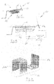
figure 1 is a perspective view of a tub of a dishwasher according to the present invention; -
figure 2 is a schematic section view of a portion of the bottom part of tub shown infigure 1 according to a first embodiment of the invention; -
figure 3 is a schematic view similar tofigure 2 according to a second embodiment of the invention and in a first configuration of use; -
figure 4 is a section view of the tub offigure 3 in a second configuration of use; -
figure 5 is a schematic section view of a portion of the bottom part of the tub shown infigure 1 according to a third embodiment of the invention; -
figure 6 is a schematic view showing the electrical system associated with the induction heating system of a dishwasher according to the invention; -
figure 7 is a perspective exploded view of a tub used in a dishwasher according to the present invention. - With reference to the drawings, a metal tub of a dishwasher is indicated with
reference 10. The tub is composed by a L-shaped bottom back 10a and by a U-shaped wrapper 10b (figure 7 ). The two metal parts 10a and 10b are roll welded together. - On the
metal tub 10 are identified several zones A where an induction heater can be associated with. With reference tofigure 2 , the bottom portion of thetub 10 is provided, on its outside surface 12, with an induction heating coil in form of abobbin 14 housed in a bobbin supporting frame 14a. According to such first embodiment, in which at least the U-shaped wrapper 10a of thetub 10 is made of ferritic steel, for instance AISI 304, the portion A of the tub is heated directly on the basis of the physical principle of eddy current heating. The high-frequency changing field induces into ferritic tub bottom eddy currents which heat up the tub (and water contained therein). Infigures 3 and 4 it is shown a second embodiment of the invention in which thetub 10 is provided with an addedferromagnetic plate 16 welded or glued to the tub and which is heated due to eddy currents induced by thebobbin 14. This embodiment is particularly indicated for laundry washing machines and for dishwashers having a tub made of polymeric material or of not ferromagnetic material (for instance austenitic stainless steel). In this case the plate and the induction heating element associated thereto may assume a curvilinear shape in order to cope with the shape of the tub. Theplate 16 then heats by conduction themetal tub 10. In this embodiment thetub 10 does not need to be of ferromagnetic material, and can be also made of polymeric material or of austenitc stainless steel. Infigure 3 it is shown the condition in which thetub 10 is filled with water W, and this configuration is typical of an early stage of the washing cycle when water is recirculated and sprayed on crockery. Infigure 4 it is shown a configuration typical of the final drying stage, in which air is circulated on the surface of the tub 10 (arrow sin the drawings) and it is heated up by the hot surface of the tub heated by the induction heating coil. - In
figure 5 it is shown a further embodiment in which only a portion of thetub 10, indicated with reference 11 infigure 5 , is made of ferromagnetic material, for instance ferritic stainless steel. In this embodiment the portion or plate 11 is integrated into the tub bottom, and it is surrounded by a heattransfer insulation part 13. In this embodiment the tub may be made of austenitic stainless steel material, and only the portion 11, i.e. the very top layer of the induction heaters, is made of ferritic material and is visible by the user. - In
figure 6 it is shown a schematic electrical circuit for theinduction heating bobbin 14 underneath the bottom of thetub 10. The spiral-shaped inductor 14 acts as the primary circuit of a transformer whose secondary circuit is short-out, the secondary winding being the ferritic tub bottom or a heating plate. Between the bottom of thetub 10 and thebobbin 14 it is interposed a layer 15 of electrical non magnetic insulation. Theinductor 14 implements an alternate current (AC) with a frequency between 25 and 35 kHz. The Inductor 14a is generating an oscillating circuit by acondenser 20. The needed power comes from aninverter circuit 22. It is not necessary to describe in detail the induction heating coil or the driving circuit thereof because these are well known to the experts in the art. The electronic control circuit of a dishwasher according to the invention comprises also a microprocessor for controlling the induction heating system, as well as a circuit for controlling the temperature reached by the tub. Such control circuit may comprise a temperature sensor (not shown) carried by a holder which is spring-biased into contact with the outside surface of thetub 10.
Claims (11)
- Washing appliance, particularly dishwashing machine, comprising a tub (10) and a heating system for heating water and/or air contained in the tub, characterized in that the heating system comprises at least an induction heating element (14, 14a) for heating at least a portion (A) of the tub (10, 10a, 10b) in contact with water and/or air.
- Washing appliance according to claim 1, wherein the tub (10) has at least a metal portion which is directly heated by the induction heating element (14, 14a).
- Washing appliance according to claim 1, wherein the induction heating element (14, 14a) is adjacent a metal plate (16) adapted to transfer heat to the tub (10).
- Washing appliance according to any of the preceding claims, wherein the induction heating element (14, 14a) is placed under a bottom portion of the tub (10a).
- Washing appliance according to claim 4, wherein the induction heating element (14, 14a) comprise a metal ferromagnetic portion (11) which is integrated into the tub bottom and it is insulated therefrom.
- Washing appliance according to any of the preceding claims, wherein the tub (10) is made of ferritic stainless steel.
- Dishwashing machine according to claims 2 and 4, wherein the bottom portion of the tub (10a) is made of ferritic stainless steel.
- Dishwashing machine according to claim 4, wherein the tub (10) comprises a U-shaped element (10b) and a L-shaped element (10a) welded together by a roll welding process, the L-shaped element forming at least a part of the bottom portion of the tub (10).
- Dishwashing machine according to claim 8, wherein the L-shaped element (10a) of the tub (10) is made of ferritic stainless steel.
- Dishwashing machine according to any of the preceding claims, wherein the induction heating element (14, 14a) is adapted to generate steam.
- Dishwashing machine according to any of the preceding claims, wherein the induction heating element (14, 14a) is associated to a channel where air is adapted to flow.
Priority Applications (4)
| Application Number | Priority Date | Filing Date | Title |
|---|---|---|---|
| PL08102497T PL2100996T3 (en) | 2008-03-11 | 2008-03-11 | Washing appliance with induction heating |
| ES08102497.8T ES2565241T3 (en) | 2008-03-11 | 2008-03-11 | Washing device with induction heating |
| EP08102497.8A EP2100996B1 (en) | 2008-03-11 | 2008-03-11 | Washing appliance with induction heating |
| PCT/EP2009/052145 WO2009112357A1 (en) | 2008-03-11 | 2009-02-24 | Washing appliance with induction heating |
Applications Claiming Priority (1)
| Application Number | Priority Date | Filing Date | Title |
|---|---|---|---|
| EP08102497.8A EP2100996B1 (en) | 2008-03-11 | 2008-03-11 | Washing appliance with induction heating |
Publications (2)
| Publication Number | Publication Date |
|---|---|
| EP2100996A1 true EP2100996A1 (en) | 2009-09-16 |
| EP2100996B1 EP2100996B1 (en) | 2016-02-17 |
Family
ID=39673364
Family Applications (1)
| Application Number | Title | Priority Date | Filing Date |
|---|---|---|---|
| EP08102497.8A Expired - Fee Related EP2100996B1 (en) | 2008-03-11 | 2008-03-11 | Washing appliance with induction heating |
Country Status (4)
| Country | Link |
|---|---|
| EP (1) | EP2100996B1 (en) |
| ES (1) | ES2565241T3 (en) |
| PL (1) | PL2100996T3 (en) |
| WO (1) | WO2009112357A1 (en) |
Cited By (11)
| Publication number | Priority date | Publication date | Assignee | Title |
|---|---|---|---|---|
| WO2010049289A1 (en) * | 2008-10-29 | 2010-05-06 | BSH Bosch und Siemens Hausgeräte GmbH | Domestic appliance for the care of laundry items having a heating device and method for heating suds and/or laundry items in a drum of a domestic appliance |
| US20110023555A1 (en) * | 2009-07-31 | 2011-02-03 | Bsh Home Appliances Corporation | Heater pocket for a household appliance |
| DE102010029075A1 (en) * | 2010-05-18 | 2011-11-24 | BSH Bosch und Siemens Hausgeräte GmbH | Laundry treatment apparatus and method for operating a laundry treatment appliance |
| US8485001B2 (en) | 2009-07-31 | 2013-07-16 | Bsh Home Appliances Corporation | Household appliance having a tub with a fluid guide |
| EP2987446A1 (en) * | 2014-08-22 | 2016-02-24 | LG Electronics Inc. | Dishwasher |
| WO2018038382A1 (en) * | 2016-08-25 | 2018-03-01 | Lg Electronics Inc. | Laundry apparatus |
| DE102017207652A1 (en) * | 2017-05-05 | 2018-11-08 | BSH Hausgeräte GmbH | Dishwasher and method for operating a dishwasher |
| WO2020032416A1 (en) * | 2017-08-09 | 2020-02-13 | Lg Electronics Inc. | Laundry treating apparatus |
| EP3505674A4 (en) * | 2016-08-25 | 2020-03-25 | LG Electronics Inc. -1- | Clothes treatment apparatus and control method therefor |
| US10941511B2 (en) | 2016-08-25 | 2021-03-09 | Lg Electronics Inc. | Clothes treatment apparatus and control method therefor |
| US11155956B2 (en) | 2018-08-09 | 2021-10-26 | Lg Electronics Inc. | Laundry treatment apparatus |
Families Citing this family (2)
| Publication number | Priority date | Publication date | Assignee | Title |
|---|---|---|---|---|
| KR102377042B1 (en) * | 2017-08-09 | 2022-03-22 | 엘지전자 주식회사 | Laundry Treating Apparatus |
| KR20200018242A (en) * | 2018-08-09 | 2020-02-19 | 엘지전자 주식회사 | A Laundry Apparatus |
Citations (4)
| Publication number | Priority date | Publication date | Assignee | Title |
|---|---|---|---|---|
| US4181846A (en) * | 1977-10-05 | 1980-01-01 | Cunningham Ronald J | Rotary heating apparatus |
| US5724750A (en) * | 1995-11-16 | 1998-03-10 | Burress; Vergel F. | Clothes dryer with Peltier effect heating, infrared heating, and vacuum drying capabilities |
| EP1507033A1 (en) * | 2003-08-13 | 2005-02-16 | LG Electronics Inc. | Washing machine with steam generator |
| US20060076037A1 (en) * | 2004-10-12 | 2006-04-13 | Lg Electronics Inc. | Dishwasher and method for controlling the same |
Family Cites Families (4)
| Publication number | Priority date | Publication date | Assignee | Title |
|---|---|---|---|---|
| JPH06133915A (en) * | 1992-10-30 | 1994-05-17 | Toshiba Corp | Tableware washing and drying machine |
| JP3744553B2 (en) * | 1994-09-29 | 2006-02-15 | 三洋電機株式会社 | Washing machine |
| DE10130193B4 (en) * | 2001-06-22 | 2006-01-26 | AEG Hausgeräte GmbH | Dishwashing carrier for a dishwasher and method for treating items to be washed in a dishwasher |
| JP2005177331A (en) * | 2003-12-22 | 2005-07-07 | Mitsubishi Electric Corp | Washing machine |
-
2008
- 2008-03-11 PL PL08102497T patent/PL2100996T3/en unknown
- 2008-03-11 EP EP08102497.8A patent/EP2100996B1/en not_active Expired - Fee Related
- 2008-03-11 ES ES08102497.8T patent/ES2565241T3/en active Active
-
2009
- 2009-02-24 WO PCT/EP2009/052145 patent/WO2009112357A1/en active Application Filing
Patent Citations (4)
| Publication number | Priority date | Publication date | Assignee | Title |
|---|---|---|---|---|
| US4181846A (en) * | 1977-10-05 | 1980-01-01 | Cunningham Ronald J | Rotary heating apparatus |
| US5724750A (en) * | 1995-11-16 | 1998-03-10 | Burress; Vergel F. | Clothes dryer with Peltier effect heating, infrared heating, and vacuum drying capabilities |
| EP1507033A1 (en) * | 2003-08-13 | 2005-02-16 | LG Electronics Inc. | Washing machine with steam generator |
| US20060076037A1 (en) * | 2004-10-12 | 2006-04-13 | Lg Electronics Inc. | Dishwasher and method for controlling the same |
Cited By (23)
| Publication number | Priority date | Publication date | Assignee | Title |
|---|---|---|---|---|
| WO2010049289A1 (en) * | 2008-10-29 | 2010-05-06 | BSH Bosch und Siemens Hausgeräte GmbH | Domestic appliance for the care of laundry items having a heating device and method for heating suds and/or laundry items in a drum of a domestic appliance |
| US20110023555A1 (en) * | 2009-07-31 | 2011-02-03 | Bsh Home Appliances Corporation | Heater pocket for a household appliance |
| WO2011012590A1 (en) * | 2009-07-31 | 2011-02-03 | BSH Bosch und Siemens Hausgeräte GmbH | Heater pocket for a household appliance |
| US8485001B2 (en) | 2009-07-31 | 2013-07-16 | Bsh Home Appliances Corporation | Household appliance having a tub with a fluid guide |
| EA019026B1 (en) * | 2009-07-31 | 2013-12-30 | Бсх Бош Унд Сименс Хаусгерете Гмбх | Household appliance |
| DE102010029075A1 (en) * | 2010-05-18 | 2011-11-24 | BSH Bosch und Siemens Hausgeräte GmbH | Laundry treatment apparatus and method for operating a laundry treatment appliance |
| US10258218B2 (en) | 2014-08-22 | 2019-04-16 | Lg Electronics Inc. | Dishwasher |
| EP2987446A1 (en) * | 2014-08-22 | 2016-02-24 | LG Electronics Inc. | Dishwasher |
| EP3505674A4 (en) * | 2016-08-25 | 2020-03-25 | LG Electronics Inc. -1- | Clothes treatment apparatus and control method therefor |
| WO2018038382A1 (en) * | 2016-08-25 | 2018-03-01 | Lg Electronics Inc. | Laundry apparatus |
| CN114045641B (en) * | 2016-08-25 | 2024-04-05 | Lg电子株式会社 | Clothes treating apparatus |
| CN114045641A (en) * | 2016-08-25 | 2022-02-15 | Lg电子株式会社 | Clothes treating device |
| US10941511B2 (en) | 2016-08-25 | 2021-03-09 | Lg Electronics Inc. | Clothes treatment apparatus and control method therefor |
| US11008694B2 (en) | 2016-08-25 | 2021-05-18 | Lg Electronics Inc. | Laundry apparatus |
| US11828016B2 (en) | 2016-08-25 | 2023-11-28 | Lg Electronics Inc. | Clothes treatment apparatus and control method therefor |
| US11421369B2 (en) | 2016-08-25 | 2022-08-23 | Lg Electronics Inc. | Clothes treatment apparatus and control method therefor |
| DE102017207652A1 (en) * | 2017-05-05 | 2018-11-08 | BSH Hausgeräte GmbH | Dishwasher and method for operating a dishwasher |
| WO2020032416A1 (en) * | 2017-08-09 | 2020-02-13 | Lg Electronics Inc. | Laundry treating apparatus |
| CN110820253B (en) * | 2017-08-09 | 2022-10-04 | Lg电子株式会社 | Clothes treating apparatus |
| US11136707B2 (en) | 2017-08-09 | 2021-10-05 | Lg Electronics Inc. | Laundry treating apparatus |
| CN110820253A (en) * | 2017-08-09 | 2020-02-21 | Lg电子株式会社 | Clothes treating apparatus |
| US11155956B2 (en) | 2018-08-09 | 2021-10-26 | Lg Electronics Inc. | Laundry treatment apparatus |
| US11905642B2 (en) | 2018-08-09 | 2024-02-20 | Lg Electronics Inc. | Laundry treatment apparatus |
Also Published As
| Publication number | Publication date |
|---|---|
| WO2009112357A1 (en) | 2009-09-17 |
| ES2565241T3 (en) | 2016-04-01 |
| EP2100996B1 (en) | 2016-02-17 |
| PL2100996T3 (en) | 2016-06-30 |
Similar Documents
| Publication | Publication Date | Title |
|---|---|---|
| EP2100996B1 (en) | Washing appliance with induction heating | |
| WO2018162211A1 (en) | A flow-through type induction heater | |
| WO1993004567A1 (en) | Rapid heating, uniform, highly efficient griddle | |
| JP5279620B2 (en) | Induction heating cooker | |
| JP5854890B2 (en) | Home appliance power control system | |
| GB2445780A (en) | Electrical induction heating liquid boiling appliance | |
| CN205664437U (en) | Electromagnetism external heating suspending device | |
| JP2006066258A (en) | Heating cooker | |
| JP2909979B2 (en) | High frequency induction heating cooker | |
| CN204445330U (en) | Cooking apparatus | |
| CN205433292U (en) | Be suitable for electromagnetic heating's interior pot, bread machine and cooking utensil | |
| AU2016333503B2 (en) | Induction heating method and system | |
| CN204648643U (en) | A kind of electromagnet water heater | |
| JP5846935B2 (en) | Power control system for induction heating cooker and home appliance | |
| CN104026985A (en) | Instant-heating-type 100-DEG C tea tray machine | |
| JP2009123603A (en) | Induction heating cooker | |
| JP2009285184A (en) | Induction heat generating body and induction heating receptacle | |
| JP2014020773A (en) | Heating cooker and control method for the same and power control system for household electrical appliances | |
| JP5642271B2 (en) | Induction heating cooker and its program | |
| JP4345491B2 (en) | Induction heating device | |
| WO2019201265A1 (en) | Clothing treating device | |
| CN108141923B (en) | Induction heating method and system | |
| CN211582985U (en) | Dish washing machine | |
| JP4528824B2 (en) | Induction heating cooker | |
| CN103875998A (en) | Induction cooker cooking method for improving energy efficiency |
Legal Events
| Date | Code | Title | Description |
|---|---|---|---|
| PUAI | Public reference made under article 153(3) epc to a published international application that has entered the european phase |
Free format text: ORIGINAL CODE: 0009012 |
|
| AK | Designated contracting states |
Kind code of ref document: A1 Designated state(s): AT BE BG CH CY CZ DE DK EE ES FI FR GB GR HR HU IE IS IT LI LT LU LV MC MT NL NO PL PT RO SE SI SK TR |
|
| AX | Request for extension of the european patent |
Extension state: AL BA MK RS |
|
| 17P | Request for examination filed |
Effective date: 20100218 |
|
| 17Q | First examination report despatched |
Effective date: 20100312 |
|
| AKX | Designation fees paid |
Designated state(s): DE ES FR GB IT PL |
|
| GRAP | Despatch of communication of intention to grant a patent |
Free format text: ORIGINAL CODE: EPIDOSNIGR1 |
|
| INTG | Intention to grant announced |
Effective date: 20151103 |
|
| GRAS | Grant fee paid |
Free format text: ORIGINAL CODE: EPIDOSNIGR3 |
|
| GRAA | (expected) grant |
Free format text: ORIGINAL CODE: 0009210 |
|
| AK | Designated contracting states |
Kind code of ref document: B1 Designated state(s): DE ES FR GB IT PL |
|
| REG | Reference to a national code |
Ref country code: GB Ref legal event code: FG4D |
|
| REG | Reference to a national code |
Ref country code: FR Ref legal event code: PLFP Year of fee payment: 9 |
|
| REG | Reference to a national code |
Ref country code: DE Ref legal event code: R096 Ref document number: 602008042356 Country of ref document: DE |
|
| REG | Reference to a national code |
Ref country code: ES Ref legal event code: FG2A Ref document number: 2565241 Country of ref document: ES Kind code of ref document: T3 Effective date: 20160401 |
|
| PGFP | Annual fee paid to national office [announced via postgrant information from national office to epo] |
Ref country code: DE Payment date: 20160308 Year of fee payment: 9 Ref country code: ES Payment date: 20160219 Year of fee payment: 9 |
|
| PGFP | Annual fee paid to national office [announced via postgrant information from national office to epo] |
Ref country code: GB Payment date: 20160309 Year of fee payment: 9 Ref country code: FR Payment date: 20160223 Year of fee payment: 9 |
|
| PGFP | Annual fee paid to national office [announced via postgrant information from national office to epo] |
Ref country code: IT Payment date: 20160725 Year of fee payment: 9 |
|
| REG | Reference to a national code |
Ref country code: DE Ref legal event code: R097 Ref document number: 602008042356 Country of ref document: DE |
|
| PLBE | No opposition filed within time limit |
Free format text: ORIGINAL CODE: 0009261 |
|
| STAA | Information on the status of an ep patent application or granted ep patent |
Free format text: STATUS: NO OPPOSITION FILED WITHIN TIME LIMIT |
|
| 26N | No opposition filed |
Effective date: 20161118 |
|
| PGFP | Annual fee paid to national office [announced via postgrant information from national office to epo] |
Ref country code: PL Payment date: 20161229 Year of fee payment: 10 |
|
| REG | Reference to a national code |
Ref country code: DE Ref legal event code: R119 Ref document number: 602008042356 Country of ref document: DE |
|
| GBPC | Gb: european patent ceased through non-payment of renewal fee |
Effective date: 20170311 |
|
| REG | Reference to a national code |
Ref country code: FR Ref legal event code: ST Effective date: 20171130 |
|
| PG25 | Lapsed in a contracting state [announced via postgrant information from national office to epo] |
Ref country code: FR Free format text: LAPSE BECAUSE OF NON-PAYMENT OF DUE FEES Effective date: 20170331 Ref country code: DE Free format text: LAPSE BECAUSE OF NON-PAYMENT OF DUE FEES Effective date: 20171003 |
|
| PG25 | Lapsed in a contracting state [announced via postgrant information from national office to epo] |
Ref country code: IT Free format text: LAPSE BECAUSE OF NON-PAYMENT OF DUE FEES Effective date: 20170311 Ref country code: GB Free format text: LAPSE BECAUSE OF NON-PAYMENT OF DUE FEES Effective date: 20170311 |
|
| REG | Reference to a national code |
Ref country code: ES Ref legal event code: FD2A Effective date: 20180710 |
|
| PG25 | Lapsed in a contracting state [announced via postgrant information from national office to epo] |
Ref country code: ES Free format text: LAPSE BECAUSE OF NON-PAYMENT OF DUE FEES Effective date: 20170312 |
|
| PG25 | Lapsed in a contracting state [announced via postgrant information from national office to epo] |
Ref country code: PL Free format text: LAPSE BECAUSE OF NON-PAYMENT OF DUE FEES Effective date: 20180311 |