JP2005177331A - Washing machine - Google Patents
Washing machine Download PDFInfo
- Publication number
- JP2005177331A JP2005177331A JP2003425608A JP2003425608A JP2005177331A JP 2005177331 A JP2005177331 A JP 2005177331A JP 2003425608 A JP2003425608 A JP 2003425608A JP 2003425608 A JP2003425608 A JP 2003425608A JP 2005177331 A JP2005177331 A JP 2005177331A
- Authority
- JP
- Japan
- Prior art keywords
- washing tub
- washing
- tub
- water
- washing machine
- Prior art date
- Legal status (The legal status is an assumption and is not a legal conclusion. Google has not performed a legal analysis and makes no representation as to the accuracy of the status listed.)
- Pending
Links
Images


Landscapes
- Detail Structures Of Washing Machines And Dryers (AREA)
- Main Body Construction Of Washing Machines And Laundry Dryers (AREA)
Abstract
Description
この発明は、水と被洗濯物とを収容する内部空間が設けられた洗濯槽を備えた洗濯機に関する。 The present invention relates to a washing machine including a washing tub provided with an internal space for storing water and laundry.
洗濯槽の側壁に脱水孔が設けられ、洗濯槽の外側面全体を覆うように外水槽が備えられた従来の洗濯機は、脱水時に、まず洗濯槽および外水槽内の大部分の水を外水槽底部に設けた排水口から排水する。その後、洗濯槽を高速回転し、その遠心力で被洗濯物に含まれる水分の多くを脱水し、脱水した水分を外水槽で受けとめる方法が一般的であった。
また、側壁に脱水孔が設けられていない洗濯槽は、洗濯槽の側壁の内径が上部ほど大径となるようにして、洗濯槽回転時の遠心力で、上縁から外水槽へ排水する方法もコーンタイプの洗濯槽として知られている。
また、被洗濯物を含む洗濯液の加熱方法として、外水槽を備える洗濯機において、洗濯液に接するように配設した磁性金属体を磁界発生手段で加熱して洗濯液を高温にする方法が提案され、洗濯液の洗浄効果を高めている。磁性金属体の配設場所として、外水槽の底部、洗濯槽の槽壁または洗濯液の循環路が例示されている(例えば、特許文献1参照。)。
また被洗濯物の乾燥方法として、洗濯槽内外で空気を循環する経路を設け、その途上で空気を加熱するヒーターを備えるものとして、外水槽を備える洗濯機において、外水槽洗濯槽の槽壁と筐体の間にヒーター、熱交換器、送風手段を設置し、ヒーターにより加熱された乾燥空気を送風手段を用いて洗濯槽に送って、洗濯物から水分を除去し、さらに熱交換器により除湿を行って乾燥空気を循環させる方式が示されている(例えば、特許文献2参照。)。
しかし、外水槽が洗濯槽の外側面の外部に備えられた洗濯機は、洗濯機の外形が同じであれば、外水槽を備えない場合に比べて洗濯槽の内容積が相対的に減り、洗濯機のデッドスペースが大きく、また、水の使用量が多いという問題があった。また、洗濯槽の側壁外側面に黒カビ等が発生し易く、さらに、黒カビ等が発生した場合それを除去することが困難であった。特に、洗濯時において、洗濯槽の側壁外側面および外水槽の側壁内面の黒カビが剥がれ、脱水孔を介して洗濯槽内の水に黒カビ等が混じり、被洗濯物に黒カビが付着し悪臭を発生するなど、衛生面での問題があった。なお、最近の洗濯機では、乾燥機能を備え、洗濯や脱水後に洗濯槽の内外面や外水槽内面を乾燥させて黒カビ等の発生を防止することができるものもあるが、毎洗濯・脱水後あるいは定期的に乾燥機能を使用する必要があり、乾燥機能のために使用電気量が増加する問題があった。
また、洗濯液を電磁誘導加熱する洗濯機では、外水槽を備えた洗濯機が前提であり、洗濯槽の槽壁を発熱部とした場合の洗濯槽の槽壁外周面や、外水槽の底部や洗濯液の循環路に配置した発熱部の清掃は困難で、たとえば乾燥時に固着したゴミが洗濯時に剥がれて被洗濯物に付着するなどの衛生上あるいは洗濯品質上の問題は避けられなかった。また、洗濯槽の槽壁を発熱部とした場合、外水槽の外からなので電磁誘導する距離が長くなり、効率よく加熱するには限界がある。また、もともと、この方式は洗濯液を加熱する手段であって、被洗濯物の乾燥への適用の言及はない上、洗濯液の循環経路は加温したまま循環することになり(液を加熱するのであればこの方がよい)、一般的に液体用のための配管は細くてよく、このまま乾燥用に用いても、乾燥に要する時間は長くなり、乾燥用に適用することは想定されていなかった。
そこで、外水槽を備えない洗濯機が提案されている。この洗濯機の洗濯槽は、側壁に脱水孔が設けられていないとともに、洗濯槽の側壁内径が下部ほど大径となっている。さらに、洗濯槽の側壁上に凹状の排水誘導溝を設けて、排水を促進している。そして、バネなどで洗濯槽内の貯留水圧に抗して閉じ、かつ遠心力によって開く排水手段を洗濯槽の側壁下部に設けられている。また、洗濯槽の下部に設けられたパルセータの回転軸を中空に形成し、洗濯槽からの排水路として兼用し、パルセータの回転軸を回転自在に支持するとともに水密シールする機能を有する回転カップラを備え、パルセータの回転軸を洗濯槽の外部へ繋がる排水管へ回転カップラで連結し、排水管の途上に排水弁を備える方法が示されている(例えば、特許文献3参照。)。
さらに、前記の電磁誘導加熱を行う技術において、誘導加熱処理用容器と磁性金属体の間に非磁性金属体を挟設する方法も提案されている。これは処理対象物として含水性処理物である生ゴミなどを乾燥させる手段として発熱体を構成し、処理容器全体を一様に電磁誘導加熱する方法として示されている(例えば、特許文献4参照。)。
A conventional washing machine provided with a dewatering hole in the side wall of the washing tub and an outer water tub so as to cover the entire outer surface of the washing tub first removes most of the water in the washing tub and the outer tub when dehydrating. Drain from the drain outlet provided at the bottom of the tank. Thereafter, a general method is to rotate the washing tub at a high speed, dehydrate much of the water contained in the laundry by the centrifugal force, and receive the dehydrated water in the outer water tub.
In addition, for a washing tub that does not have a dewatering hole on the side wall, the inner diameter of the side wall of the washing tub becomes larger toward the upper part, and the water is drained from the upper edge to the outside water tub by centrifugal force when the washing tub rotates. Is also known as a corn-type washing tub.
In addition, as a method of heating the washing liquid including the laundry, there is a method of heating the magnetic metal body disposed so as to be in contact with the washing liquid with a magnetic field generating means in a washing machine having an outer water tub so that the washing liquid is heated to a high temperature. It has been proposed to enhance the washing effect of the washing liquid. Examples of the location of the magnetic metal body include the bottom of the outer water tank, the tank wall of the washing tub, or the circulation path of the washing liquid (see, for example, Patent Document 1).
In addition, as a method for drying the laundry, a path for circulating air inside and outside the washing tub is provided, and a heater for heating the air is provided on the way. A heater, heat exchanger, and air blowing means are installed between the cases, and dry air heated by the heater is sent to the washing tub using the air blowing means to remove moisture from the laundry, and further dehumidified by the heat exchanger. The system which circulates dry air and performs is shown (for example, refer patent document 2).
However, the washing machine in which the outer tub is provided outside the outer surface of the washing tub has a relatively smaller inner volume of the washing tub as compared with the case where the outer tub is not provided, as long as the outer shape of the washing machine is the same. There was a problem that the dead space of the washing machine was large and the amount of water used was large. In addition, black mold or the like is likely to be generated on the outer surface of the side wall of the washing tub. Further, when black mold or the like is generated, it is difficult to remove it. Especially during washing, black mold on the outer side wall of the washing tub and the inner side wall of the outer tub is peeled off, and black mold is mixed with the water in the washing tub through the dewatering hole, and black mold adheres to the laundry and generates bad odor. There were hygiene problems such as. In addition, some recent washing machines have a drying function and can dry out the inner and outer surfaces of the washing tub and the inner surface of the outer tub after washing and dehydration to prevent the occurrence of black mold, etc. Or it was necessary to use a drying function regularly, and there was a problem that the amount of electricity used increased because of the drying function.
In addition, the washing machine that electromagnetically heats the washing liquid is premised on a washing machine having an outer water tub, and the outer peripheral surface of the tub wall when the tub wall of the washing tub is used as a heat generating part, or the bottom of the outer tub In addition, it is difficult to clean the heat generating portion disposed in the circulation path of the washing liquid, and for example, sanitation or washing quality problems such as dust adhering at the time of drying and peeling off at the time of washing are unavoidable. Moreover, when the tank wall of the washing tub is used as a heat generating portion, the distance for electromagnetic induction becomes long because it is from the outside of the outer water tub, and there is a limit to efficient heating. In addition, this method is originally a means for heating the washing liquid, and there is no mention of application to drying of the laundry, and the circulation path of the washing liquid is circulated while being heated (heating the liquid). If this is the case, this is better) In general, the pipe for liquid may be thin, and even if it is used for drying as it is, the time required for drying will be long and it is not assumed to be applied for drying. It was.
Therefore, a washing machine that does not include an external water tank has been proposed. The washing tub of this washing machine has no dewatering hole in the side wall, and the inner diameter of the side wall of the washing tub becomes larger toward the lower part. Furthermore, a concave drainage guide groove is provided on the side wall of the washing tub to promote drainage. And the drainage means which closes against the stored water pressure in a washing tub with a spring etc., and opens by centrifugal force is provided in the side wall lower part of the washing tub. Further, a rotary coupler having a function of forming a hollow shaft of the pulsator provided in the lower part of the washing tub and also serving as a drainage channel from the washing tub, and rotatably supporting the rotation shaft of the pulsator and water-tightly sealing it. A method of providing a drainage valve in the middle of a drainage pipe by connecting a rotary shaft of the pulsator to a drainage pipe connected to the outside of the washing tub with a rotary coupler is shown (for example, see Patent Document 3).
Furthermore, in the technique for performing electromagnetic induction heating, a method of sandwiching a nonmagnetic metal body between an induction heat treatment container and a magnetic metal body has been proposed. This is shown as a method in which a heating element is configured as a means for drying raw garbage that is a water-containing processed product as a processing target, and the entire processing container is uniformly heated by electromagnetic induction (see, for example, Patent Document 4). .)
しかし、外水槽ほどではないが、遠心力で排水する排水弁の配置に合わせて洗濯槽の下部を覆うように排水を受ける排水槽が必要となるとともに、上記の様な排水弁の設置そのものが、回転範囲が大きく、洗濯機のデッドスペースを大きくする問題がある。
また、遠心力で排水する排水弁は、洗濯槽が回転しないと排水できないので、それだけでは排水時間が長くなったり、洗濯槽が回転しなくとも排水できる、別の排水手段が必要となる問題がある。
また、回転しながら、水密シールできる、回転カプラが必然であり、水密シールしない場合に比べて回転抵抗が増加する問題がある。また、摩耗によって、水密シール性能が低下する問題がある。
また、循環経路内の空気をヒーターに接触させて加熱するため、被洗濯物からのゴミなどがヒーターに付着し、絶縁不良を起こす原因となり易く、ヒーター寿命が低下する可能性があった。また、ゴミが付着しても清掃することが困難であった。さらには、上記ヒーターは、被洗濯物を乾燥すること以外には基本的に使用していなかった。
さらに、処理容器と磁性金属体との間に被磁性金属体を挟設する方式においては、処理容器を洗濯槽に当てはめると、磁性金属本体に黒カビやゴミの付着が懸念され、処理容器を外さないと清掃することも困難である。その結果付着したまま使用していると、加熱効果が時間と共に減少したり、洗濯時に剥がれたゴミや黒カビが非洗濯物に付着する衛生上あるいは洗濯品質上の問題があった。
However, although it is not as much as the outside water tank, a drainage tank that receives drainage is required to cover the lower part of the washing tub according to the arrangement of the drainage valve that drains by centrifugal force, and the installation of the drainage valve as described above is necessary. There is a problem that the rotation range is large and the dead space of the washing machine is increased.
Also, since the drain valve that drains by centrifugal force cannot drain unless the washing tub rotates, there is a problem that drainage time becomes longer, or another draining means that can drain even if the washing tub does not rotate is necessary. is there.
In addition, a rotating coupler capable of watertight sealing while rotating is inevitable, and there is a problem that rotational resistance increases as compared with a case where watertight sealing is not performed. Further, there is a problem that the watertight seal performance is deteriorated due to wear.
Further, since the air in the circulation path is heated by contacting the heater, dust from the laundry is likely to adhere to the heater and cause insulation failure, which may reduce the life of the heater. Further, it is difficult to clean even if dust adheres. Furthermore, the heater was basically not used except for drying the laundry.
Furthermore, in the system in which the magnetic metal body is sandwiched between the processing container and the magnetic metal body, if the processing container is applied to the washing tub, there is a concern that black mold or dust may adhere to the magnetic metal body, and the processing container is removed. Otherwise, it is difficult to clean. As a result, when used while attached, there were problems in terms of hygiene or washing quality in which the heating effect decreased with time, and dust and black mold peeled off during washing adhered to non-laundry items.
この発明の目的は、洗濯時およびゆすぎ時に黒かび等が付着する衛生上の問題が少ないとともに清掃が容易となり、安全性が高くメンテナンスが容易で、かつゴミの付着が少ない乾燥ができる洗濯機を提供することである。 An object of the present invention is to provide a washing machine that can be dried with less sanitary problems to which black mold or the like adheres during washing and rinsing, facilitates cleaning, is safe and easy to maintain, and has little dust adhesion. Is to provide.
この発明に係わる洗濯機は、通水性を有さない槽側壁を有する回転可能な筒状の洗濯槽を備えた洗濯機において、上記槽側壁の内側に着脱自在な通水性を有する脱水板を槽側壁と間隔を空けて備えた。 The washing machine according to the present invention is a washing machine having a rotatable cylindrical washing tub having a tank side wall that does not have water permeability, and a dewatering plate having water permeability that is detachably attached to the inside of the tank side wall. Provided spaced apart from the side wall.
この発明に係わる洗濯機の効果は、洗濯槽の回転による脱水時に、水を含む被洗濯物が脱水板に遠心力で押しつけられて、脱水板と槽壁との間に形成される通水路または脱水板自体に備えた通水路または脱水板の表裏を貫通する通水孔を通して被洗濯物に含まれる水が流れ易くなり、脱水する効果が上がるとともに、脱水板を着脱自在とすることで、脱水板が付設された部分の洗濯槽の槽壁や脱水板自体の清掃が容易となり、黒カビ等が発生しても除去が可能で清潔性の維持が容易となる。乾燥時においては、脱水板と洗濯槽の槽壁間の通水路によって確実に送風路を確保でき、送風時の動力ロスが少なくなる。 The effect of the washing machine according to the present invention is that when the laundry is dewatered by rotation of the washing tub, the laundry containing water is pressed against the dewatering plate by centrifugal force, and the water passage formed between the dewatering plate and the tub wall or The water contained in the laundry becomes easy to flow through the water passage provided in the dehydration plate itself or the water passage hole that passes through the front and back of the dehydration plate, and the dehydration effect is improved. It becomes easy to clean the wall of the washing tub in the part where the plate is attached and the dewatering plate itself, and even if black mold or the like is generated, it can be removed and the cleanliness can be easily maintained. During drying, the air passage can be reliably secured by the water passage between the dehydrating plate and the tub wall of the washing tub, and power loss during blasting is reduced.
実施の形態1.
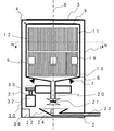
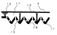
図1はこの発明の実施の形態1に係わる洗濯機の縦断面図である。図2は実施の形態1の洗濯機の横断面図である。図3はこの実施の形態1の洗濯機における脱水板と洗濯槽との周辺の拡大断面模式図である。なお、図1は図2のA−A断面図であり、図2は図1のB−B断面図である。
1 is a longitudinal sectional view of a washing machine according to
この洗濯機は、洗濯機の各部位を収納する角筒形状の筐体1を有し、筐体1には角筒の開口端の一端を閉じる底板2と他端を開閉する外蓋3とが設けられている。筐体1は底板2を洗濯機の設置箇所に接するように設置してある。また、筐体1の上部には、図示しない電源の入切および運転モード選択などを行うスイッチ類と運転状況および水位などを表示する表示器類などが配置されている。筐体1は塗装鋼板、ステンレスまたは樹脂で作られている。
This washing machine has a rectangular tube-
さらに、洗濯機は、筐体1内に収容され、回転自在に支持された有底円筒形状の洗濯槽4を有し、洗濯槽4は円筒形状の側部5とその円筒形状の一端部を閉じる底部6からなる。この底部6は筐体1の底板2に対面するように配置され、洗濯槽4の一端の開口部は筐体1の外蓋3に面するように配置されている。洗濯槽4の底部6は洗濯槽4の外側に突き出た頭を切った円錐形状であり、底部6は筐体1に固定された軸受7により水平面内で回転自在に支持されている。洗濯槽4の底部6は、回転中心軸8に沿った切頭円錐形状であり、排水が容易な構成となっている。洗濯槽4の自重、水および被洗濯物はこの軸受7によって回転するように支持されている。円筒形状の洗濯槽4は円筒の中心軸を中心にして回転でき、以降この中心軸を洗濯槽4の回転中心軸8と称す。洗濯槽4の上端部には洗濯槽4の上部の開口部を開閉する内蓋9が設けられている。洗濯槽4は衛生の観点からステンレスで作られているのが望ましい。
Further, the washing machine has a bottomed
なお、筐体1と洗濯槽4の上部の開口部は、被洗濯物の出し入れのために開けられていて、その開口部を覆うように、自在に開閉できる外蓋3と内蓋9とが取り付けられている。洗濯時および脱水時など洗濯槽4が回転しているときには、外蓋3および内蓋9によって筐体1および洗濯槽4の上部の開口部が閉じられ、水滴の飛散防止および防音の機能を果たす。なお、外蓋3または内蓋9を必ずしも備えなくてもよく、少なくとも一方は備えてなくてもよい。
また、洗濯槽4は、内蓋9が閉じられ、かつ後述する排水弁21が閉じられているときには底部6および側部5を含む洗濯槽4の壁には洗濯槽4の内外で通水することができる脱水孔が設けられておらず、洗濯するときには洗濯槽4の上部の図示しない給水口から洗濯槽4内へ給水がなされる。
In addition, the opening part of the upper part of the housing | casing 1 and the
The
次に、洗濯槽4の内部に脱水板11が配置されている。脱水板11は、洗濯槽4の側部5の内面に対向し、周方向に4分割され、これらを組み合わせると1つの円筒になり、軸方向に間隙を有して2分割され、組み合わせると2つの円筒になる側面脱水板12と、洗濯槽4を底部6と側部5とを分ける位置に底部脱水板13とからなる。図3に示すように脱水板11は、波板状であり、脱水板11には脱水板11の表裏で通水ができるように設けられた脱水孔14が設けられている。さらに脱水板11の洗濯槽4の内面に対向する面に脱水板11を洗濯槽4に支持するための脱水板脚部15が設けられ、この脱水板脚部15と洗濯槽4の内面との間を吸盤16で着脱可能に支持されている。このように支持された脱水板11と洗濯槽4の内面との間に通水路17と脱水溝18とが形作られ、脱水時の水の通路の役割をはたす。図3では、脱水孔14を開けた波板状とし、内面側に脱水溝18を形成し、特に脱水時に排水し易くしている。また、脱水板脚部15を設けることで、通水路17を十分大きくとることができる。一方、底部脱水板13は、扇状に4分割された円盤からなり、着脱自在となるように設置されている。図1では底部脱水板13を水平に配置できるように、脱水板脚部15の長さを底部脱水板13の周辺部では短く、中央部に向かうほど長くなるように変えている。脱水板11はステンレス鋼板からできている。
Next, a dehydrating plate 11 is disposed inside the
なお、底部脱水板13は、図1のような水平な配置ではなく、洗濯槽4の円錐状の底部6の内面に沿うように配置したり、円盤状の中央部を頂点とした円錐形となるように配置してもよい。また、底部脱水板13にも側面脱水板12と同様に、後述する攪拌翼19が固定されていてもよい。攪拌翼19は、複数に分割された側面脱水板12や底部脱水板13などの脱水板11の繋ぎ目を利用したり、脱水板11の一部を開けたり、脱水板11を設置しない場所を設けたりして、洗濯槽4の槽壁内面側に固定するようにしてもよい。
また、側面脱水板12は、図1では回転中心軸8の軸方向に2分割、洗濯槽4の回転方向に4分割されているので、装脱着単位が小さくなり、側面脱水板12の装脱着がより容易となる。なお、側面脱水板12の分割の数および水平に対する角度もそれぞれ異なっていてもよい。
The
Further, in FIG. 1, the side surface dewatering plate 12 is divided into two parts in the axial direction of the
また、脱水板11は洗濯槽4の槽壁へ図3に示すように脱水板脚部15を介して吸盤16によって取り付けられているが、槽壁側に設けた部材と脱水板脚部15に取り付けた部材を嵌め込むようにするなど、洗濯槽4の回転によっても不安定にならないように強固に取り付けることができればこれに限らない。脱水板11を分割している場合に、隙間に被洗濯物が入り込まないようにするため、分割の繋ぎ目はあまり大きく取らないようにすることが望ましい。
また、脱水板11の内外を貫通する構造として、図3に示すように内外を貫通する脱水孔14が設けられているが、脱水板11を網にしてもよい。
また、脱水板11は図3に示すように波板状であるが、脱水板11は平板でもよいし、表面をエンボス加工し、エンボスの凹部などに脱水孔14を備えた板状でも良い。さらには、脱水板11の少なくとも一部を通水性や吸水性の高い多孔質体や吸水性のある高分子体などで構成すると、脱水孔14は必ずしも備えてなくてもよい。また、脱水板11が波板状などの厚み方向に波打っているときには、脱水板脚部15を特に備えていなくてもよい。脱水板脚部15の長さの代わりに、脱水板11の波打ちの高さで、洗濯槽4の通水路17の高さが確保可能である。
Further, the dewatering plate 11 is attached to the tub wall of the
Further, as shown in FIG. 3, a dewatering hole 14 penetrating inside and outside is provided as a structure that penetrates the inside and outside of the dewatering plate 11, but the dewatering plate 11 may be a net.
Further, the dewatering plate 11 has a corrugated plate shape as shown in FIG. 3, but the dehydrating plate 11 may be a flat plate, or a plate shape in which the surface is embossed and the embossed recesses are provided with the dewatering holes 14. Furthermore, if at least a part of the dewatering plate 11 is made of a porous body having high water absorption or water absorption, a polymer having water absorption, or the like, the dewatering holes 14 are not necessarily provided. Further, when the dewatering plate 11 is wavy in the thickness direction such as a corrugated plate, the dewatering plate leg portion 15 may not be particularly provided. Instead of the length of the dewatering plate leg 15, the height of the
次に、図1に戻って側面脱水板12には、洗濯槽4とともに回転することによって洗濯槽4内の被洗濯物が浮遊している水に水流を起こすための攪拌翼19が固定されている。図2に示すように攪拌翼19は洗濯槽4の回転方向に4個が均等な位置に設置されている。個々の攪拌翼19は断面が流線型である平板状の翼で、洗濯槽の回転方向に対して斜めに設置されている。攪拌翼19は樹脂からできているが、金属であってもよい。
なお、それぞれ洗濯槽の回転方向に不均等な位置に配置してもよい。また、攪拌翼19は取り付けたものではなく、脱水板11に一体成型されたものでもよい。また、攪拌翼19は洗濯槽4の内側に突き出た突起物状のものであってもよく、洗濯槽4が回転するにつれて、洗濯槽4内に水流を起こせるようなものであればよい。ただし、被洗濯物を極力痛めないようにするため、攪拌翼19には鋭角な部分がない方が望ましい。
Next, referring back to FIG. 1, the side dewatering plate 12 is fixed with a
In addition, you may arrange | position in an uneven position in the rotation direction of a washing tub, respectively. Further, the stirring
さらに、洗濯槽4は、洗濯槽4の底部6の切頭円錐の切頭部の開口に固定され、洗濯槽4に貯められた水を外部に排出する排水路を形成する円筒形状の排水管20と、排水管20の中に固定され、排水路の開閉を行う排水弁21とが備えられている。排水管20の入口には、図示しないフィルターをはめ込んでおき、排水時や乾燥時に洗濯槽4からゴミなどが流れ出るのを極力防止するようにしておくことが望ましい。排水管20の出口の近傍には排水路で導かれた排水を受ける排水槽22が筐体1に支持されており、その排水槽22から筐体1の外部に排水を導く排水導出管23が筐体1の側面または底面を貫通して設けられている。排水槽22には排水槽22の水位を検出し、排水槽22の水位が所定の水位に達したとき排水弁21を閉じる水位センサ24が備えられている。この排水弁21と排水槽22との間を離して排水を受けるようにするほうが望ましく、水密シールする必要はない。接続は機械的に接続するのではなく、浮かせて間接的に排水を受けるようにすればよい。排水弁21は電磁弁でもよいし、別途筐体1側に取り付けた図示しないモータ等の動力源を利用して機械的に動作させる弁としてもよい。排水管20、排水弁21は洗濯槽4と一体構成とし、洗濯槽4が回転しているときには一体となって回転するように構成する。なお、排水槽22を特に設けず、筐体1の底板2を排水槽として代用するようにしてもよい。
さらに、図4、5を参照して詳しく排水弁21を説明する。図4は排水弁21が閉止しているときの拡大断面図であり、図5は排水弁21が開放されているときの拡大断面図である。排水管20は円筒状である。排水弁21は、その排水管20の下部に内側面が円錐状で外側面が円柱状の排水管20の内部に挿入されて固定されている弁受部40と、その弁受部40に挿入され、下限位置に降下したとき弁受部40と係合する切頭円錐状の弁体41とを有する。弁体41を回転中心軸8の軸方向に上昇したとき排水管20を開き排水管20からの排水量を調節する弁体41と弁受部40との間に隙間が形成される。さらに、排水弁21は、弁体41を回転中心軸8のまわりに回転自在に支持する回転軸42と、その回転軸42を支持し、回転軸42を上下に昇降する昇降部材43と、昇降部材43を上下に昇降する駆動軸44とを有している。洗濯槽4が回転し、排水弁21が閉止されているときには、排水弁21は洗濯槽4および排水管20と一体となって回転する。また、昇降部材43を昇降するための駆動軸44は昇降部材43との接触部がギア状になっており、図示しないモータで駆動軸44を回転することで、昇降部材43が昇降するようになっている。
なお、排水管20、排水弁21、排水槽22、排水導出管23の材質は、カビが付着しにくいものとしてステンレスを用いている。しかし、他の金属系材料、あるいは軽量化のため抗菌剤を含有したプラスチック樹脂(ポリプロピレン、ABS等)を用いてもよい。特に、排水弁21より下流の排水管20、排水槽22、排水導出管23については、カビや汚れが付着しても洗濯槽に戻ることがないので、ステンレスや抗菌性のある材質を用いる必然はない。
Further, the
Further, the
The
次に、図1に戻って、洗濯槽4の下方に洗濯槽4を回転する槽回転手段30が備えられている。槽回転手段30は、モータ32と、モータ32の動力軸31と、動力軸31の回転を洗濯槽4と連結した排水管20に固定された図示しないプーリに回転を伝える動力伝達機構33と、モータ32を駆動するインバータ34とを有している。動力伝達機構33、動力軸31、モータ32からなる槽回転手段30は、一体型のASSYとして構成されている。
なお、モータ32は、直流モータ、同期モータまたは誘導モータなどであればよいが、長寿命でありかつ省エネルギとする観点から、あるいは現在最も使用用途が一般的でかつ量産されており低価格が期待できる誘導モータが望ましい。
なお、筐体1から図示しないバネなどを介してモータ32を支持したり、動力軸31に弾性を持たせたりして、洗濯槽4の回転に伴う揺動に対して尤度をもたせるほうが望ましい。
Next, returning to FIG. 1, a
The motor 32 may be a direct current motor, a synchronous motor, an induction motor, or the like. However, from the viewpoint of long life and energy saving, or currently the most commonly used and mass-produced, the motor 32 is inexpensive. An induction motor that can be expected is desirable.
In addition, it is preferable that the motor 32 is supported from the
次に、洗濯機の動作について説明する。洗濯槽4の回転中心軸8の回転方向により「正モード」と「逆モード」を定義する。ただし正モード、逆モードは洗濯槽の上方から見た場合の時計回り、反時計回りのいずれでもよいが、ここでは正モードを時計回り、逆モードを反時計回りとする。洗濯時の動作においては、被洗濯物と水と洗剤を洗濯槽4に入れ、モータ32を正モードで回転させる。モータ32の回転動力は動力軸31、動力伝達機構33そして図示しないプーリを経由して、洗濯槽4を正モードに回転する。回転するにつれて攪拌翼19により洗濯槽4の内部の水と被洗濯物の混合物も回転し、複雑な水流となって被洗濯物の洗浄が行われる。次に一定時間、例えば1分間後に、モータ32の回転方向を変更して逆モードを実施する。このような正モード、逆モードの組合せを数回繰り返した後に、排水弁21を開いて排水する。図4において、排水弁21は、駆動軸44を図示しないモータで回転させて、駆動軸44にギアで連結した昇降部材43が回転中心軸8の軸方向(上部)へ移動することで、回転軸42および弁体41も移動して、弁受部40と弁体41との間に隙間が開いて、排水する。なお、止水する場合は、駆動軸44を上記とは逆に回転して弁受部40と弁体41との間の隙間を閉じることで行う。排水時においては水位センサ24により排水槽22の水位を検知して排水弁21の開閉動作を行う。たとえば、排水槽22の水位が低ければ、排水弁21を開け、水位が高ければ、閉める。このとき排水槽22から水が漏出しないような水位を設定する。なお、排水管20からの排水量に比して排水導出管23の配管サイズを大きくするなどして排水導出管23の排水量を充分大きくすれば、洗濯槽4からの排水時において排水槽22の水位に応じて排水弁21の開閉動作を必ずしなければならないというものではなく、排水弁21の繰り返し開閉動作や水位センサ24を省略することも可能である。
Next, the operation of the washing machine will be described. The “normal mode” and “reverse mode” are defined by the rotation direction of the
次に、すすぎ時の動作については、排水弁21を閉じた後に、水を洗濯槽4に再度注入して、洗濯槽4を回転させるが、基本的には洗濯時と同じ動作のため詳細な説明は省略する。
Next, regarding the operation at the time of rinsing, after closing the
次に、脱水時の動作について説明する。排水弁21を開く動作を行い、モータ32をインバータ制御して洗濯槽4の回転速度を洗濯時の動作時よりも大きくして行う。被洗濯物から排出された水は、遠心力および重力による作用で、底部脱水板13や側面脱水板12の脱水溝18や脱水孔14や通水路17を介し、さらに排水管20や排水弁21を介して排水槽22に送られ、排水導出管23を介して筐体1の外に排水される。
Next, the operation during dehydration will be described. The operation of opening the
このような洗濯機は、洗濯槽が回転しているとき、水が貯められた洗濯槽の内部で洗濯槽の動きと異なる動きをする排水槽が接しておらず、洗濯槽に貯められた水を洗濯槽とともに回転する排水弁で静的に水密シールしているので、回転水密シールにともなう排水槽以外への水漏れを抑制できる。また、回転水密シール部がなく、静的な水密シールの排水弁だけなので、摩耗による部品交換が不要となるとともに、洗濯槽の回転時の動力ロスが低減できる。
また、水位センサにより排水槽の水位を常時監視しているので、排水槽からの水溢れを防止できる。
また、洗濯槽内以外、例えば外水槽などへの給水が必要無いので、必要最小限の使用水量での洗濯が可能となる。
また、脱水板を着脱自在の構造としているので、カビなどの汚れが付着しても、洗浄することが容易である。
また、脱水板の装着位置であるので、脱水板の装着が容易である。
In such a washing machine, when the washing tub is rotating, there is no contact with a drainage tub that moves differently from the movement of the washing tub inside the washing tub in which water is stored. Since the water-tight seal is statically sealed with the drain valve that rotates together with the washing tub, water leakage to other than the drain tub accompanying the rotating water-tight seal can be suppressed. Moreover, since there is no rotating watertight seal portion and only a static watertight seal drain valve, it is not necessary to replace parts due to wear, and power loss during rotation of the washing tub can be reduced.
Moreover, since the water level of the drainage tank is constantly monitored by the water level sensor, the overflow from the drainage tank can be prevented.
Further, since there is no need to supply water other than the inside of the washing tub, for example, the outside water tub etc., washing with the minimum required amount of water becomes possible.
In addition, since the dehydrating plate is detachable, it is easy to clean even if dirt such as mold adheres.
Moreover, since it is a mounting position of the dehydrating plate, it is easy to mount the dehydrating plate.
なお、排水管20の側面から接触するようにした軸受またはベアリング機構を介して、洗濯槽4の回転を支持するようにしていてもよく、このようにすることで洗濯槽4の回転のぶれをより一層抑制することができる。なお、洗濯槽4の重量を支持する軸受と回転自在に支持する図示しないベアリング機構とを別々に備えていてもよいし、兼用していてもよい。
The rotation of the
実施の形態2.
図6はこの発明の実施の形態2に係わる洗濯機の脱水板の周辺の拡大断面模式図である。実施の形態1の脱水板11と異なる点は、脱水板11を脱水溝18がない平板状としたことと、脱水板脚部15と洗濯槽4の双方に取り付けた装着レール10を噛み合わせることによって洗濯槽4に装着したことである。
FIG. 6 is an enlarged schematic cross-sectional view of the periphery of the dewatering plate of the washing machine according to
このようにすることで、脱水板11が洗濯槽4により確実に装着されるので、洗濯槽4が回転しても脱水板11が外れてしまうことがない。
By doing so, the dewatering plate 11 is securely attached to the
実施の形態3.
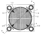
図7はこの発明の実施の形態3に係わる洗濯機の縦断面図である。図8は実施の形態3の洗濯機の横断面図である。なお、図7は図8のA−A断面図であり、図8は図7のB−B断面図である。この実施の形態3の洗濯機が実施の形態1の洗濯機と異なる点は、洗濯槽と筐体との間に配置された乾燥機構をさらに備えたことである。その他は同様であるので、同様な部分に同じ符号を付記し、説明を省略する。
7 is a longitudinal sectional view of a washing machine according to
図7に示すように、乾燥機構50は、筐体1と洗濯槽4との間に設置され、筐体1の下部から空気を吸入する下部送風路51と、筐体1の上部に乾燥空気を排出する上部送風路52と、これら下部送風路51と上部送風路52との間に設置された熱交換器53と、上部送風路52の途上に設置され、図示しないモータで回転して送風循環するための送風ファン54と、洗濯槽4の少なくとも一部を覆うように筐体1に固定されている誘導加熱手段としての外部固定子55と、外部固定子55に交流電流を流すインバータ56とを有する。図8に示すように、熱交換器53、下部送風路51、上部送風路52および送風ファン54の組み合わせを4組、筐体1の4隅に設置しており、筐体1内のスペースを有効に活用している。なお、ここでは4組としたが、4組でなくてもよい。
As shown in FIG. 7, the
また、下部送風路51、上部送風路52および熱交換器53と洗濯槽4の間に図示しない断熱材などを詰めるか、または、一部を板で封止して、少なくとも下部送風路51および上部送風路52以外では極力送風循環しないようにしておく。また、モータ32、動力軸31および動力伝達機構33などからなる槽回転手段30も、図示しない容器に納めるようにして、極力循環風に曝されないようにする。なお、このようにするとき洗濯槽4の回転に支障がない範囲で行い、密閉するまでのものではない。洗濯槽4の槽壁外周面の少なくとも一部(外部固定子55が巻かれている部分以外が好ましい。)には図示しない断熱材を付設するようにしてもよい。このようにすることで放熱が減るので、洗濯槽4内だけを効率よく加熱することが可能となる。
Further, a lower air passage 51, an upper air passage 52, a
熱交換器53は、下部送風路51中の空気を冷却して除湿するためのものであり、プレートフィン形式やシェルアンドチューブ形式などの2流体熱交換器構造を備え、筐体1外からの水と循環風とを熱交換するようにしたり、筐体1外の空気を送風して循環風と熱交換するようにしたりするものであればよい。この除湿した際に発生する水は、排水槽22へ排水するようにしてもよいし、別途水タンクを備えて貯めておき、次の洗濯時に使用するようにしてもよい。
The
外部固定子55は、磁界発生コイルであり、2kHz以上の周波数の交流電力を印加することにより交流磁界を発生させて、少なくとも一部は磁性金属(磁性ステンレスや鉄など)からなる洗濯槽4の槽壁内部に渦電流を生じさせて加熱する。すなわち、この外部固定子55は、洗濯槽4の槽壁を電磁誘導加熱するものである。そのため、洗濯槽4の外部であって筐体1内の部材の材質は、電磁誘導加熱しないような非磁性ステンレス、アルミニウムなどの非磁性金属またはプラスチックなどが好ましい。外部固定子55のコイルには、周波数が高い方が効率よく電磁誘導加熱できるので周波数2〜60KHzの交流電力を発生するインバータ56が接続されている。なお、外部固定子55が洗濯槽4と離れていると電磁誘導する効率が下がるので、洗濯槽4の回転に支障がない範囲で極力外部固定子55が近接するように設置する。また、外部固定子55を樹脂または碍子などの絶縁材で覆ったり、容器に入れたりするなどして水密処置および絶縁処置を施して、循環風に曝され難くしておくことが望ましい。なお、加熱対象の洗濯槽4の槽壁は磁性金属としているが、非磁性金属であってもよい。これは洗濯槽4が回転していて外部固定子55の磁界に対して速度を持っていると、非磁性金属内にも渦電流が流れる現象が知られており、非磁性金属で十分に用を成すことになる。
The external stator 55 is a magnetic field generating coil that generates an AC magnetic field by applying AC power having a frequency of 2 kHz or more, and at least a part of the
次に、洗濯機の動作について説明する。実施の形態1と同様な部分については説明を省略し、異なる部分について説明する。洗濯時の動作においては、被洗濯物の汚れ度合いに応じて外部固定子55に交流電圧をインバータ56から印加することで、洗濯槽4の槽壁を加熱する。洗濯槽4の槽壁が加熱されると洗濯槽4内の水および被洗濯物が加熱されるので、洗剤などに含まれる界面活性作用および酵素活性作用が促進され、被洗濯物の汚れの除去が促進される。温度については過度に昇温させる必要は無く、30〜40℃が適当であるが、これ以外の温度であってもよい。また、昇温する温度は、汚れ度合いに応じたものでなくてもよい。
すすぎと脱水が行われるときの動作は実施の形態1と同様であるため、ここでは説明を省略する。
Next, the operation of the washing machine will be described. A description of the same parts as those in the first embodiment will be omitted, and different parts will be described. In the operation at the time of washing, the wall of the
Since the operation when rinsing and dehydration are performed is the same as that of the first embodiment, the description thereof is omitted here.
次に、乾燥時の動作について説明する。脱水時の動作が終了した後、または脱水動作中から、外部固定子55に交流電圧を印加することで、洗濯槽4の槽壁を加熱する。また、加熱と同時に送風ファン54を回転すると、洗濯槽4内の少なくとも通水路17を上部から下部へ、さらに排水管20、排水弁21を経由して洗濯槽4の外側へ、さらに下部送風路51を経由して熱交換器53へ、さらに熱交換器53から送風ファン54および上部送風路52を経由して洗濯槽4内上部への一連の循環経路で空気が送風される。洗濯槽4の槽壁の加熱によって洗濯槽4内の循環風および被洗濯物が加熱され、洗濯槽4、側面脱水板12および底部脱水板13に付着した水分および被洗濯物中の水分が循環風中に蒸発する。このように水分を多く含む高温な循環風は、排水管20、排水弁21を通って洗濯槽4外へ排出され、下部送風路51を通って熱交換器53へ送られる。熱交換器53内では水分を多く含む高温な循環風が冷却され、循環風中の水分の一部が熱交換器53内で結露する。結露した水分が多くなると、熱交換器53内および下部送風路51内を流れ落ち(この場合、循環風とは逆方向である)、排水槽22へ送られ、排水導出管23を経由して筐体1外へ排水される。一方、熱交換器53において水分の一部が除去された循環風は、上部送風路52、送風ファン54を経由して洗濯槽4内上部へと送風される。
Next, the operation during drying will be described. After the operation at the time of dehydration is completed or during the dehydration operation, the tank wall of the
このように外水槽が備えられず、脱水板11を備えた洗濯槽4の槽壁を電磁誘導加熱するようにしたので、従来のヒーター式よりも発熱部のゴミの付着が少なく、清掃が容易であり、安全性が高く、発熱部の寿命が長くなる。また、外部固定子55で洗濯時に洗濯槽4を加熱することにも兼用でき、洗濯時の洗浄効果を高めることができる。また、脱水板11で被洗濯物と離間された洗濯槽4の槽壁が外部固定子55と近接して配置されているので、効率よく電磁誘導加熱でき、また洗濯槽4が直接被洗濯物に触れず、均一でマイルドな加熱・乾燥が可能である。また、乾燥時において通水路17によって確実に洗濯槽4内における送風路が確保でき、送風時の動力ロスが少なくなる。
As described above, since the outside water tank is not provided and the tank wall of the
なお、この実施の形態3の乾燥動作時において、洗濯槽4を回転するようにしてもよい。このようにすると、洗濯槽4内において被洗濯物の位置が常に移動するので、よりむらの少ない乾燥ができ、その結果、被洗濯物の皺などができにくくなり、傷みを少なくすることができる。
Note that the
また、循環風の方向は逆方向であってもよい。すなわち、洗濯槽4内の下部から上部へ、さらに上部送風路52、送風ファン54を経由して熱交換器53へ、さらに下部送風路51から洗濯槽4外の下部へ、さらに排水弁21、排水管20を経由して洗濯槽4内へという順序である。このようにすると、熱交換器53での結露水の落下する方向が循環風と方向が同じくなるので、熱交換器53での結露水の流れ落ちがより容易で早くなる。また、被洗濯物を下側から吹き上げるので、循環風と被洗濯物との接触機会が増え、よりむらの少ない乾燥ができる。さらに、洗濯槽4内における上昇気流の効果と、洗濯槽4外における下降気流の効果で、循環風を循環する動力を低減できる。
Further, the direction of the circulating air may be the reverse direction. That is, from the lower part in the
また、乾燥時における洗濯槽4の槽壁の加熱温度は特に指定していないが、より高温である方が乾燥時間を短くすることができる。また、温度検知して外部固定子55へ供給する交流電力の周波数や電力を調節することによって、循環風の温度を60℃程度となるようにすれば、皺が少なく、被洗濯物の傷みも少ない乾燥が可能である。
Moreover, although the heating temperature of the tank wall of the
また、洗濯槽4の槽壁を電磁誘導加熱するようにしたが、脱水板11を電磁誘導加熱するようにしてもよい。このとき、脱水板11の材質は磁性金属とし、脱水板11と洗濯槽4の槽壁の距離は、脱水時に大きな支障がない範囲で最小限とする。また、少なくとも電磁誘導加熱する脱水板11の位置に対応した洗濯槽4の槽壁は磁界を遮らない、たとえばプラスチック製とすることが望ましい。ただし、脱水板11と洗濯槽4の槽壁を両方加熱する場合はこの限りではない。このようにすることで、脱水板11と洗濯槽4の槽壁間の通水路17は脱水時の通水路であるのでその間隔を最小限に狭くできるので、外水槽を備える場合よりは電磁誘導する距離が短く、効率よく誘導加熱できる。また通水路17が断熱層として働くので、放熱量が減り被洗濯物を有効に加熱乾燥できる。また、通水路17が確実な送風路となるので、脱水板11の過剰発熱を防止できる。
Further, although the tank wall of the
また、外部固定子55を洗濯槽4の回転方向を取り巻くように設置しているが、回転方向の一部に配置するようにしてもよい。洗濯槽4を回転することで、回転方向全周に亘って電磁誘導加熱することができる。また、外部固定子55の磁界方向を洗濯槽4の槽壁に概ね垂直となるように配置してもよい。
Moreover, although the external stator 55 is installed so that the rotation direction of the
また、洗濯槽4の槽壁または脱水板11を電磁誘導により加熱することだけで被洗濯物を乾燥するようにしているが、乾燥時は従来方式のようにヒーターなどで循環風を加熱する方式としたり、電磁誘導加熱する方式と併用したりするようにしてもよい。少なくとも、着脱自在とした脱水板11により、洗濯槽4内の清掃が容易である。さらに、脱水板11と洗濯槽4の槽壁間の通水路17によって確実に送風路が確保でき、送風時の動力ロスが少なくなる効果がある。また、従来の循環風の加熱方式と併用して洗濯槽4の槽壁や脱水板11を補助的に電磁誘導加熱するようにすることで、洗濯槽4内をむら無く均一に加熱し、被洗濯物を皺が少なく乾燥する効果がある。上記従来の循環風の加熱方式として、ヒーターの代わりに、循環風の流路途上に冷媒を蒸発する蒸発器と冷媒を凝縮する凝縮器を蒸発器の下流側に配置し、蒸発器で循環風を冷却して水分を凝縮し、凝縮器で循環風を加熱する、いわゆるヒートポンプ機構に依っても良い。このようにすることで、乾燥時におけるエネルギ消費を低減することができる。
なお、上記実施の形態3では、洗濯槽の外部側の全周方向に、あるいは洗濯槽の外部側で断面が四角の筐体と洗濯槽の間の4隅に電磁誘導コイルを配置して、電磁誘導加熱する構成で例示しているが、これに限った構成でなくてもよい。例えば、4隅のうちの1隅だけに電磁誘導コイルを配置するだけでもよい。洗濯槽を回転しながら電磁誘導加熱することで、電磁誘導コイルの高さ位置にある洗濯槽全周を結果的に均等に加熱することになり、実施の形態と同様な効果を奏するとともに、部材点数を低減できる。
In addition, the laundry is dried only by heating the tank wall of the
In the third embodiment, electromagnetic induction coils are arranged at the four corners between the casing and the washing tub having a square cross section on the outer peripheral side of the washing tub or on the outer side of the washing tub, Although illustrated by the configuration of electromagnetic induction heating, the configuration is not limited to this. For example, the electromagnetic induction coil may be disposed only at one of the four corners. By rotating the washing tub with electromagnetic induction heating, the entire circumference of the washing tub at the height position of the electromagnetic induction coil is heated evenly as a result, and the same effect as in the embodiment is achieved, and the member The score can be reduced.
実施の形態4.
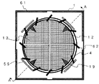
図9はこの発明の実施の形態4に係わる洗濯機の縦断面図である。図10は実施の形態4の洗濯機の横断面図である。なお、図9は図10のA−A断面図であり、図10は図9のB−B断面図である。この実施の形態4の洗濯機が実施の形態3の洗濯機と異なる点は、乾燥機構の一部である。その他は同様であるので、同様な部分に同じ符号を付記し、説明を省略する。
FIG. 9 is a longitudinal sectional view of a washing machine according to
実施の形態3に示す図7と異なる点として、図7の乾燥機構50の代わりに図9の乾燥機構60は、筐体1の内面に取り付けた放熱フィン61と、洗濯槽4の上部に環状に取り付けた送風手段としての送風ファン62と、実施の形態3と同様に誘導加熱手段としての外部固定子55と、インバータ56とを有する。また、洗濯槽4と筐体1との間の空間全体を送風路とし、排水槽22が筐体1の底板2全体を覆っている。
また、図示はしていないが、モータ32、動力軸31、動力伝達機構33、外部固定子55および軸受7などを極力循環風に曝されないように防湿被覆、一部を板で封止または容器に納めたりしてある。なお、このようにするときには、洗濯槽4の回転に支障がない範囲で行い、密閉までは必ずしも必要ない。
9 differs from FIG. 7 shown in the third embodiment in that a drying mechanism 60 in FIG. 9 instead of the
Although not shown, the motor 32, the power shaft 31, the power transmission mechanism 33, the external stator 55, the
送風ファン62は、実施の形態3の送風ファン54とは異なり、洗濯槽4と一体となっており、洗濯槽4と一緒になって回転する。送風ファン62と筐体1または外蓋3との間は、送風効率を上げる意味で隙間をなるべく少なくするように設置する。洗濯時など送風を必要としない時には、隙間を広げられるように図示しない可動可能なスペーサー、たとえば筐体1の内面寸法に合った板で、洗濯槽4の上部に合わせて中央が開いた板を昇降させるようにする機構を備えることが望ましい。また、脱水時において洗濯槽4を高速回転する際には、送風ファン62による回転抵抗を減らすため、洗濯槽4上部から洗濯槽4内へ吸引する方向の送風ファンとしての回転方向とは逆方向へ回転するようにしてもよい。また送風ファン62の材質は軽量でかつ100℃程度まで耐熱性のある軟らかいものが好ましい。また送風ファン62の形状については洗濯槽4への被洗濯物の出し入れに邪魔にならないようにすることが好ましい。
Unlike the
放熱フィン61は、筐体1の外面の空気で、内面側の循環風を冷却するために、熱交換効率を上げようとするものである。図9および10では筐体1内面側に大きく出っ張らないフィンのように描いているが、より洗濯槽4の槽壁に近い位置まで拡大したものでもよい。放熱フィン61と循環風の接触面積が大きくなり熱交換効率が上げられる。また、放熱フィン61は筐体1の内面側に設置するのではなく、筐体1の外面側に設置するようにしてもよく、その場合でも同様な効果を奏する。さらには、筐体1の内外面両側に設置してもよく、より熱交換効率を上げられる。
The heat dissipating fins 61 are intended to increase the heat exchange efficiency in order to cool the circulating air on the inner surface side with the air on the outer surface of the
次に動作について説明する。実施の形態1及び3とほぼ同様であり、異なる部分を中心に説明する。乾燥時の動作において脱水時の動作が終了した後に、外部固定子55に交流電圧を印加することで、側面脱水板12または洗濯槽4を電磁誘導加熱する。これと同時に洗濯槽4を脱水時の動作と同様に回転させ、一体となっている送風ファン62を回転させる。その結果、洗濯槽4の上部から下部へ、排水管20、排水弁21を経由して洗濯槽4外下部へ、筐体1と洗濯槽4の槽壁外部との間の空間を経由して洗濯槽4の上部にある送風フィン62への循環経路で循環風が送風される。洗濯槽4の槽壁の加熱によって洗濯槽4内の循環風および被洗濯物が加熱され、洗濯槽4、側面脱水板12および底部脱水板13に付着した水分と被洗濯物中の水分とが循環風中に蒸発する。このように水分を多く含む高温な循環風は、排水管20、排水弁21を通って洗濯槽4外下部へ排出され、筐体1と洗濯槽4の槽壁外部との間の空間を上昇する過程で、一部が放熱フィン61に接触する。放熱フィン61で水分を多く含む高温な循環風が冷却され、循環風中の水分の一部が放熱フィン61で結露する。結露した水分が多くなると、放熱フィン61および筐体1内面を流れ落ち、排水槽22へ送られ、排水導出管23を経由して筐体1外へ排水される。一方、放熱フィン61において水分の一部が除去された循環風は、洗濯槽4上部の送風ファン62に再び吸引される。
Next, the operation will be described. This is almost the same as in the first and third embodiments, and different parts will be mainly described. After the operation at the time of dehydration is completed in the operation at the time of drying, the side surface dewatering plate 12 or the
このように洗濯槽4の上部に送風ファン62を取り付けたので、実施の形態3で述べた効果に加え、洗濯槽4外の送風用のファンが不要となり、スペースの節約となり、部品点数が少なくなる。
Since the blower fan 62 is attached to the upper part of the
なお、排水槽22を別途備えるのではなく、筐体1の底板2をそのまま排水槽にすれば部品点数が削減できる。
また、洗濯槽4上部から循環風が流れ込むように構成したが、逆であってもよい。また、一方向へ流すのではなく、洗濯槽4の回転方向を変えるだけで、正逆両方向へ流すようにすることも容易にでき、適当な時間間隔で、循環風の方向を変えるようにしても良い。洗濯槽4内において吹き上げになったり下降流になったりして、よりむらの少ない乾燥ができる。
The number of components can be reduced if the
Moreover, although it comprised so that a circulation wind might flow from the
また、洗濯槽4の上部に送風ファン62を取り付けるようにしたが、洗濯槽4の槽壁外周面に出っ張るように翼を取り付けるようにしたり、洗濯槽4の上部内側面の一部であって洗濯時の最大水位より高い位置に図10と同様な翼を取り付けたり、排水管20の下端や排水弁21の出口側に径を小さくした図10と同様な翼を取り付けるようにしてもよい。
Moreover, although the ventilation fan 62 was attached to the upper part of the
また、送風手段としての送風ファン62を、図11に示すような形状として、洗濯槽4の内蓋と兼用するようにしてもよい。図11では3個の吸入スリットが開いており、洗濯槽4が回転することで、この吸入スリットから空気が吸い込まれる。内蓋の位置に設置しているので送風ファン62が汚れた場合でも、清掃が容易となる。
Moreover, you may make it also use the ventilation fan 62 as a ventilation means as an inner cover of the
なお、本発明の洗濯機以外への用途として、洗濯機の洗濯槽と同様な回転槽を備えかつ熱源を要する機器である乾燥機や、内容物の脱水をする脱水機への適用が可能であることは言うまでもない。 As a use other than the washing machine of the present invention, it can be applied to a dryer having a rotating tub similar to the washing tub of the washing machine and requiring a heat source, and a dehydrator for dehydrating the contents. Needless to say.
1 筐体、2 底板、3 外蓋、4、 洗濯槽、5、 (洗濯槽の)側部、6、 (洗濯槽の)底部、7、 軸受、8、 回転中心軸、9、 内蓋、10 装着レール、11 脱水板、12 側面脱水板、13 底部脱水板、14 脱水孔、15 脱水板脚部、16 吸盤、17 通水路、18 脱水溝、19 攪拌翼、20 排水管、21 排水弁、22 排水槽、23 排水導出管、24 水位センサ、30 槽回転手段、31 動力軸、32 モータ、33 動力伝達機構、34、56 インバータ、40 弁受部、41 弁体、42 回転軸、43 昇降部材、44 駆動軸、50、60 乾燥機構、51 下部送風路、52 上部送風路、53 熱交換器、54、62 送風ファン、55 外部固定子、61 放熱フィン。
1 casing, 2 bottom plate, 3 outer lid, 4, washing tub, 5, side of (washing tub), 6, bottom of (washing tub), 7, bearing, 8, rotation center shaft, 9, inner lid, 10 mounting rail, 11 dewatering plate, 12 side dewatering plate, 13 bottom dewatering plate, 14 dewatering hole, 15 dewatering plate legs, 16 suction cup, 17 water passage, 18 dewatering groove, 19 stirring blade, 20 drainage pipe, 21 drainage valve , 22 Drainage tank, 23 Drainage discharge pipe, 24 Water level sensor, 30 Tank rotation means, 31 Power shaft, 32 Motor, 33 Power transmission mechanism, 34, 56 Inverter, 40 Valve receiver, 41 Valve body, 42 Rotation shaft, 43 Lifting member, 44 Drive shaft, 50, 60 Drying mechanism, 51 Lower air passage, 52 Upper air passage, 53 Heat exchanger, 54, 62 Blower fan, 55 External stator, 61 Radiation fin.
Claims (5)
上記槽側壁の内側に着脱自在な通水性を有する脱水板を槽側壁と間隔を空けて備えたことを特徴とする洗濯機。 In a washing machine including a rotatable cylindrical washing tub having a tub side wall that does not have water permeability,
A washing machine comprising a dewatering plate having water permeability that is detachably attached to the inside of the tank side wall and spaced from the tank side wall.
5. The washing machine according to claim 4, further comprising a blowing unit that is detachably provided in the washing tub and rotates with the washing tub to send air into the washing tub.
Priority Applications (1)
| Application Number | Priority Date | Filing Date | Title |
|---|---|---|---|
| JP2003425608A JP2005177331A (en) | 2003-12-22 | 2003-12-22 | Washing machine |
Applications Claiming Priority (1)
| Application Number | Priority Date | Filing Date | Title |
|---|---|---|---|
| JP2003425608A JP2005177331A (en) | 2003-12-22 | 2003-12-22 | Washing machine |
Publications (1)
| Publication Number | Publication Date |
|---|---|
| JP2005177331A true JP2005177331A (en) | 2005-07-07 |
Family
ID=34785441
Family Applications (1)
| Application Number | Title | Priority Date | Filing Date |
|---|---|---|---|
| JP2003425608A Pending JP2005177331A (en) | 2003-12-22 | 2003-12-22 | Washing machine |
Country Status (1)
| Country | Link |
|---|---|
| JP (1) | JP2005177331A (en) |
Cited By (19)
| Publication number | Priority date | Publication date | Assignee | Title |
|---|---|---|---|---|
| WO2010049289A1 (en) | 2008-10-29 | 2010-05-06 | BSH Bosch und Siemens Hausgeräte GmbH | Domestic appliance for the care of laundry items having a heating device and method for heating suds and/or laundry items in a drum of a domestic appliance |
| EP2194331A2 (en) | 2008-12-02 | 2010-06-09 | BSH Bosch und Siemens Hausgeräte GmbH | Domestic continuous-flow heater |
| US7930785B2 (en) * | 2005-12-22 | 2011-04-26 | Lg Electronics Inc. | Method for cleaning a tub in a washing machine and a washing machine performing the same |
| EP2400052A1 (en) * | 2010-06-25 | 2011-12-28 | Vestel Beyaz Esya Sanayi Ve Ticaret A.S. | An induction heating system |
| RU2447214C2 (en) * | 2006-10-19 | 2012-04-10 | Электролюкс Хоум Продактс Корпорейшн Н.В. | Household washing machine with induction heating |
| CN102677422A (en) * | 2012-05-09 | 2012-09-19 | 南京乐金熊猫电器有限公司 | Washing machine |
| WO2015133200A1 (en) * | 2014-03-07 | 2015-09-11 | 日産自動車株式会社 | Fluid control valve |
| EP2100996B1 (en) * | 2008-03-11 | 2016-02-17 | Whirlpool Corporation | Washing appliance with induction heating |
| CN104381994B (en) * | 2014-11-14 | 2016-06-01 | 王丽 | The preparation method of a kind of instant Auricularia |
| EP3287559A1 (en) * | 2016-08-25 | 2018-02-28 | LG Electronics Inc. | Laundry apparatus |
| US20180057996A1 (en) * | 2016-08-25 | 2018-03-01 | Lg Electronics Inc. | Laundry apparatus |
| WO2018091717A1 (en) | 2016-11-21 | 2018-05-24 | Chiriatti Antonio Francesco | Heating system for an apparatus for the treatment of textiles |
| CN112210946A (en) * | 2019-07-11 | 2021-01-12 | 青岛海尔洗衣机有限公司 | Washing machine and control method thereof |
| WO2021032036A1 (en) * | 2019-08-20 | 2021-02-25 | 青岛海尔滚筒洗衣机有限公司 | Washing machine and control method therefor |
| CN112760902A (en) * | 2020-12-25 | 2021-05-07 | 珠海格力电器股份有限公司 | Washing cylinder assembly, control method and washing and drying machine |
| CN113308841A (en) * | 2020-02-27 | 2021-08-27 | 青岛海尔滚筒洗衣机有限公司 | Clothes treatment device |
| JP2022120044A (en) * | 2017-08-09 | 2022-08-17 | エルジー エレクトロニクス インコーポレイティド | Clothing treatment device and control method of the same |
| US11828016B2 (en) | 2016-08-25 | 2023-11-28 | Lg Electronics Inc. | Clothes treatment apparatus and control method therefor |
| US11976403B2 (en) | 2019-06-21 | 2024-05-07 | Electrolux Appliances Aktiebolag | Laundry treating appliance |
-
2003
- 2003-12-22 JP JP2003425608A patent/JP2005177331A/en active Pending
Cited By (28)
| Publication number | Priority date | Publication date | Assignee | Title |
|---|---|---|---|---|
| US7930785B2 (en) * | 2005-12-22 | 2011-04-26 | Lg Electronics Inc. | Method for cleaning a tub in a washing machine and a washing machine performing the same |
| RU2447214C2 (en) * | 2006-10-19 | 2012-04-10 | Электролюкс Хоум Продактс Корпорейшн Н.В. | Household washing machine with induction heating |
| EP2100996B1 (en) * | 2008-03-11 | 2016-02-17 | Whirlpool Corporation | Washing appliance with induction heating |
| WO2010049289A1 (en) | 2008-10-29 | 2010-05-06 | BSH Bosch und Siemens Hausgeräte GmbH | Domestic appliance for the care of laundry items having a heating device and method for heating suds and/or laundry items in a drum of a domestic appliance |
| EP2194331A2 (en) | 2008-12-02 | 2010-06-09 | BSH Bosch und Siemens Hausgeräte GmbH | Domestic continuous-flow heater |
| DE102008044280A1 (en) | 2008-12-02 | 2010-06-10 | BSH Bosch und Siemens Hausgeräte GmbH | House area heater |
| EP2400052A1 (en) * | 2010-06-25 | 2011-12-28 | Vestel Beyaz Esya Sanayi Ve Ticaret A.S. | An induction heating system |
| CN102677422A (en) * | 2012-05-09 | 2012-09-19 | 南京乐金熊猫电器有限公司 | Washing machine |
| WO2015133200A1 (en) * | 2014-03-07 | 2015-09-11 | 日産自動車株式会社 | Fluid control valve |
| US10559837B2 (en) | 2014-03-07 | 2020-02-11 | Nissan Motor Co., Ltd. | Fluid control valve |
| CN104381994B (en) * | 2014-11-14 | 2016-06-01 | 王丽 | The preparation method of a kind of instant Auricularia |
| EP3569760A1 (en) * | 2016-08-25 | 2019-11-20 | LG Electronics Inc. -1- | Laundry apparatus |
| US11008694B2 (en) * | 2016-08-25 | 2021-05-18 | Lg Electronics Inc. | Laundry apparatus |
| US11828016B2 (en) | 2016-08-25 | 2023-11-28 | Lg Electronics Inc. | Clothes treatment apparatus and control method therefor |
| US20180057996A1 (en) * | 2016-08-25 | 2018-03-01 | Lg Electronics Inc. | Laundry apparatus |
| EP3287559A1 (en) * | 2016-08-25 | 2018-02-28 | LG Electronics Inc. | Laundry apparatus |
| US10590588B2 (en) | 2016-08-25 | 2020-03-17 | Lg Electronics Inc. | Laundry apparatus |
| US10988890B2 (en) | 2016-08-25 | 2021-04-27 | Lg Electronics Inc. | Laundry apparatus |
| US11050297B2 (en) | 2016-11-21 | 2021-06-29 | Electrolux Appliances Aktiebolag | Laundry treating apparatus |
| CN110036149A (en) * | 2016-11-21 | 2019-07-19 | 伊莱克斯家用电器股份公司 | For handling the heating system of the equipment of textile |
| WO2018091717A1 (en) | 2016-11-21 | 2018-05-24 | Chiriatti Antonio Francesco | Heating system for an apparatus for the treatment of textiles |
| JP2022120044A (en) * | 2017-08-09 | 2022-08-17 | エルジー エレクトロニクス インコーポレイティド | Clothing treatment device and control method of the same |
| US11976403B2 (en) | 2019-06-21 | 2024-05-07 | Electrolux Appliances Aktiebolag | Laundry treating appliance |
| CN112210946A (en) * | 2019-07-11 | 2021-01-12 | 青岛海尔洗衣机有限公司 | Washing machine and control method thereof |
| WO2021032036A1 (en) * | 2019-08-20 | 2021-02-25 | 青岛海尔滚筒洗衣机有限公司 | Washing machine and control method therefor |
| WO2021170022A1 (en) * | 2020-02-27 | 2021-09-02 | 青岛海尔滚筒洗衣机有限公司 | Clothing treatment device |
| CN113308841A (en) * | 2020-02-27 | 2021-08-27 | 青岛海尔滚筒洗衣机有限公司 | Clothes treatment device |
| CN112760902A (en) * | 2020-12-25 | 2021-05-07 | 珠海格力电器股份有限公司 | Washing cylinder assembly, control method and washing and drying machine |
Similar Documents
| Publication | Publication Date | Title |
|---|---|---|
| JP2005177331A (en) | Washing machine | |
| KR100743707B1 (en) | Drum washer having a tub coupled to cabinet and a drying device | |
| CN109554901A (en) | A kind of drying washing machine | |
| KR20190097596A (en) | Apparatus for treating laundry | |
| JP2003311068A (en) | Drying/washing machine | |
| JP4691473B2 (en) | Washing and drying machine | |
| JP2012161511A (en) | Drum washing/drying machine | |
| JP4685588B2 (en) | Washing and drying machine | |
| JP4921026B2 (en) | Washing and drying machine | |
| JP2005177330A (en) | Washing machine | |
| JP2007330570A (en) | Washing and drying machine | |
| JP2011120746A (en) | Clothes dryer | |
| JP2009034306A (en) | Clothes dryer | |
| JP2007330569A (en) | Washing and drying machine | |
| JP2005224621A (en) | Drum type washing/drying machine | |
| JP4758273B2 (en) | Washing and drying machine | |
| JP2011067235A (en) | Drum type washing and drying machine | |
| JP2011078474A (en) | Drainage trap device for washing machine, trap cover for drainage trap device, and washing and drying machine | |
| JP2007143679A (en) | Washing/drying machine | |
| CN216891624U (en) | Closed drying and dewatering washing machine with dewatering inner barrel provided with convex ribs | |
| JP2008272137A (en) | Washing and drying machine | |
| JP2003311065A (en) | Drying/washing machine | |
| JP4616151B2 (en) | Washing and drying machine | |
| JP2023033724A (en) | Washing and drying machine | |
| JP2000225288A (en) | Washing and drying machine |
Legal Events
| Date | Code | Title | Description |
|---|---|---|---|
| A621 | Written request for application examination |
Free format text: JAPANESE INTERMEDIATE CODE: A621 Effective date: 20060131 |
|
| A977 | Report on retrieval |
Free format text: JAPANESE INTERMEDIATE CODE: A971007 Effective date: 20080522 |
|
| A131 | Notification of reasons for refusal |
Free format text: JAPANESE INTERMEDIATE CODE: A131 Effective date: 20080527 |
|
| A02 | Decision of refusal |
Free format text: JAPANESE INTERMEDIATE CODE: A02 Effective date: 20080930 |