EP2099345B1 - Mixervorrichtung zum schneiden von nahrungsmittelartikeln in gewünschte formen - Google Patents
Mixervorrichtung zum schneiden von nahrungsmittelartikeln in gewünschte formen Download PDFInfo
- Publication number
- EP2099345B1 EP2099345B1 EP20070859188 EP07859188A EP2099345B1 EP 2099345 B1 EP2099345 B1 EP 2099345B1 EP 20070859188 EP20070859188 EP 20070859188 EP 07859188 A EP07859188 A EP 07859188A EP 2099345 B1 EP2099345 B1 EP 2099345B1
- Authority
- EP
- European Patent Office
- Prior art keywords
- housing
- drive unit
- cutter
- top wall
- feed chute
- Prior art date
- Legal status (The legal status is an assumption and is not a legal conclusion. Google has not performed a legal analysis and makes no representation as to the accuracy of the status listed.)
- Not-in-force
Links
- 235000013305 food Nutrition 0.000 title claims abstract description 65
- 238000005520 cutting process Methods 0.000 title claims abstract description 39
- 238000004140 cleaning Methods 0.000 claims abstract description 9
- 230000002093 peripheral effect Effects 0.000 claims description 4
- 238000010276 construction Methods 0.000 description 8
- 230000008878 coupling Effects 0.000 description 3
- 238000010168 coupling process Methods 0.000 description 3
- 238000005859 coupling reaction Methods 0.000 description 3
- 230000007246 mechanism Effects 0.000 description 3
- 235000012055 fruits and vegetables Nutrition 0.000 description 2
- 235000002595 Solanum tuberosum Nutrition 0.000 description 1
- 244000061456 Solanum tuberosum Species 0.000 description 1
- 238000012986 modification Methods 0.000 description 1
- 230000004048 modification Effects 0.000 description 1
Images






Classifications
-
- B—PERFORMING OPERATIONS; TRANSPORTING
- B26—HAND CUTTING TOOLS; CUTTING; SEVERING
- B26D—CUTTING; DETAILS COMMON TO MACHINES FOR PERFORATING, PUNCHING, CUTTING-OUT, STAMPING-OUT OR SEVERING
- B26D7/00—Details of apparatus for cutting, cutting-out, stamping-out, punching, perforating, or severing by means other than cutting
-
- B—PERFORMING OPERATIONS; TRANSPORTING
- B26—HAND CUTTING TOOLS; CUTTING; SEVERING
- B26D—CUTTING; DETAILS COMMON TO MACHINES FOR PERFORATING, PUNCHING, CUTTING-OUT, STAMPING-OUT OR SEVERING
- B26D3/00—Cutting work characterised by the nature of the cut made; Apparatus therefor
- B26D3/28—Splitting layers from work; Mutually separating layers by cutting
- B26D3/283—Household devices therefor
-
- B—PERFORMING OPERATIONS; TRANSPORTING
- B26—HAND CUTTING TOOLS; CUTTING; SEVERING
- B26D—CUTTING; DETAILS COMMON TO MACHINES FOR PERFORATING, PUNCHING, CUTTING-OUT, STAMPING-OUT OR SEVERING
- B26D7/00—Details of apparatus for cutting, cutting-out, stamping-out, punching, perforating, or severing by means other than cutting
- B26D7/22—Safety devices specially adapted for cutting machines
- B26D7/24—Safety devices specially adapted for cutting machines arranged to disable the operating means for the cutting member
-
- Y—GENERAL TAGGING OF NEW TECHNOLOGICAL DEVELOPMENTS; GENERAL TAGGING OF CROSS-SECTIONAL TECHNOLOGIES SPANNING OVER SEVERAL SECTIONS OF THE IPC; TECHNICAL SUBJECTS COVERED BY FORMER USPC CROSS-REFERENCE ART COLLECTIONS [XRACs] AND DIGESTS
- Y10—TECHNICAL SUBJECTS COVERED BY FORMER USPC
- Y10S—TECHNICAL SUBJECTS COVERED BY FORMER USPC CROSS-REFERENCE ART COLLECTIONS [XRACs] AND DIGESTS
- Y10S83/00—Cutting
- Y10S83/929—Particular nature of work or product
- Y10S83/932—Edible
-
- Y—GENERAL TAGGING OF NEW TECHNOLOGICAL DEVELOPMENTS; GENERAL TAGGING OF CROSS-SECTIONAL TECHNOLOGIES SPANNING OVER SEVERAL SECTIONS OF THE IPC; TECHNICAL SUBJECTS COVERED BY FORMER USPC CROSS-REFERENCE ART COLLECTIONS [XRACs] AND DIGESTS
- Y10—TECHNICAL SUBJECTS COVERED BY FORMER USPC
- Y10T—TECHNICAL SUBJECTS COVERED BY FORMER US CLASSIFICATION
- Y10T83/00—Cutting
- Y10T83/485—Cutter with timed stroke relative to moving work
- Y10T83/494—Uniform periodic tool actuation
- Y10T83/50—Reciprocating tool
Definitions
- the present application relates to food processor appliances, and particularly to such appliances for cutting food articles into desired forms.
- the conventional appliance of this type generally includes rotary cutter or shredder blades, examples of such appliances being described in US Patents 4,546,928 , 4,928,893 and 6,748,853 .
- Such appliances cannot be used to cut food articles in certain forms, such as into longitudinally-extending sticks or the like; they are also difficult to clean.
- Appliances are also known which include reciprocating cutter members, rather than rotary cutter members.
- An example of an appliance including a reciprocatory cutter member is described in US Patent 5,445,332 .
- the known appliances of this type also have a number of drawbacks, particularly with respect to ease of disassembly and reassembly for cleaning purposes, and/or the various forms in which the food articles can be cut.
- An object of the present invention is to provide a food processor appliance of the reciprocractory cutter member type having advantages in one or more of the above respect.
- a food processor appliance for cutting food articles into a desired form, comprising: a housing including a removable top wall; a feed chute carried by the top wall, and removable therewith, the feed chute having an inlet end projecting outwardly of the top wall, and an outlet end leading through the top wall into the housing; a pusher member for pushing food articles through the feed chute into the housing; a cutter device within the housing and aligned with the outlet end of the feed chute, the cutter device being mounted for reciprocatory forward and return movements transversely across the outlet end of the feed chute for cutting food articles fed therethrough into the desired form; and an electrical drive unit including an electrical motor controlled by an on/off switch for reciprocating the cutter device; the electrical drive unit being conveniently attachable to the bousing for reciprocating the cutter device, and removably from the housing to facilitate cleaning the cutting device; the electrical drive unit including an interlock electrical switch normally disabling the drive unit, but actuatable to enable the drive unit; the feed chute includes an actuator laterally thereof for
- the feed chute is of a cylindrical configuration, and a drive tlie.side thereof facing the electrical drive unit includes the laterally-extending pin.
- the side of the electrical drive unit formed with the socket includes a curved recess conforming to the curvature of the feed chute; and the bottom of the electrical drive unit is formed with two further sockets for receiving pins formed at the respective end of the housing top wall to precisely locate the electrical drive unit with respect to the feed chute and housing top wall.
- the electrical drive unit includes a top wall and opposed side walls formed with recesses configured to serve as hand grips facilitating grasping the electrical drive unit for application to, or removal of, the electrical drive unit with respect to the housing top wall.
- a food processor appliance constructed in accordance with the foregoing features may be conveniently disassembled for cleaning purposes, and then conveniently reassembled for proper operation.
- a food processor appliance for cutting food articles into a desired form, comprising: a housing including a removable top wall; a feed chute carried by the top wall, and removable therewith, the feed chute having an inlet end projecting outwardly of the top wall, and an outlet end leading through the top wall into the housing; a pusher member for pushing food articles through the feed chute into the housing; a cutter device within the housing and aligned with the outlet end of the feed chute, the cutter device being mounted for reciprocatory forward and return movements transversely across the outlet end of the feed chute for cutting food articles fed therethrough into the desired form; and a drive for reciprocating the cutter device; the cutter device including a first blade extending transversely across the path of movement of the cutter holder during its reciprocations; and a group of spaced further blades extending perpendicularly to the first blade and parallel to the path of movement of the cutter holder during its reciprocations, such that the cutter member cuts the food articles into longitudinally-extending strips.
- the first blade extends substantially horizontally parallel to the removable top wall of the housing, and the group of spaced further blades extends substantially vertically with respect to the removable top wall of the housing.
- the cutter member includes a blade extending transversely across the path of movement of the cutter holder during its reciprocations; the blade having a cutting edge on each of its opposite ends such as to cut a slice of the food article during both the forward and return reciprocatory movements of the cutter device.
- the foregoing features provide an appliance that can be used for cutting food articles, such as fruits and vegetables, into a wide variety of different forms and shapes, and which can also be conveniently assembled and disassembled for cleaning purposes.
- the food processor appliance illustrated in the drawings is designed particularly for cutting food articles into various desired forms, such as shreddings, slices, sticks, and the like, and also to permit convenient disassembly and reassembly of the appliance for cleaning purposes.
- the appliance includes a housing, generally designated 2; a feed chute 3 for feeding food articles into the housing; a cutter device 4 within the housing mounted for reciprocatory movements for cutting the food articles; a pusher member 5 for pushing the food articles via feed chute 3 into contact with the cutter device 4; and an electrical drive unit 6 for reciprocating the cutter devise 4.
- housing 2 includes an outer housing member 21, an inner removable liner 22, and a removable receptacle 23 received within the housing to underlie the cutter device 4 for receiving the cuttings produced thereby.
- the top of the housing is closed by a removable top wall 24.
- the inner surface of the two side walls of housing member 21 are stepped inwardly to define a pair of longitudinally-extending rails 25 on which the cutter device 4 is mounted for reciprocatory movements under the feed chute 3 carried by the removable top wall 24.
- housing member 21 is formed with a thickened rim 21a on three sides, the fourth side being formed with a projecting pin 21b.
- the removable top wall 24 is formed on all four sides with a depending flange 24a dimensioned to be received with a friction fit over the thickened rim 21a of housing member 21.
- flange 24a engageable with the side of housing member 21 not formed with a thickened rim, but rather formed with projecting pin 21b, as shown in Fig. 2 is formed with an opening 24b for receiving pin 21b.
- Such a construction permits removable top wall 24 to be conveniently attached to housing 21 by first passing pin 21b through opening 24b of the top wall while the top wall is in an angular position with respect to housing member 21, and then pivotting the top wall to cause its depending flange 24a to engage the thickened rim 21 a of housing member 21 with a friction fit,
- Removable top wall 24 of housing 2 is further formed with a pair of upstanding pins 26 at one end, and with a longitudinally-extending slot 27 between the pins.
- pins 26 cooperate with the electrical drive unit 6 to properly locate it in the assembled condition of the appliance, and slot 27 cooperates with electrical drive unit for coupling its reciprocatory drive to cutter device 4 within housing 2.
- Housing 2 further includes a pair of resilient strips 28 fixed to the bottom wall of its :outer housing member 21 at its opposite ends, to permit the appliance to be stably supported on a flat horizontal surfaces.
- Feed chute 3 through which the food articles are pushed by pusher member 5 into the housing into contact with the cutter device 4 therein, is of cylindrical configuration. Preferably, it is of a relatively large diameter to accommodate whole food articles, so as not to necessitate the cutting of the food articles into smaller pieces before fed into the feed chute.
- the upper end of feed chute 3 projects outwardly of the removable top wall 24 to facilitate me introduction of feed articles into the feed tube.
- the opposite end 31 of the feed tube, which serves as its outlet, is preferably fixedly mounted on the removable top wall 24 of housing 2, with the respective edge of feed chute 3 flush with the inner surface of the top wall 24.
- the upper end of feed chute 3 includes a projection 33 at the side thereof facing me electrical drive unit 6.
- projection 33 serves as an actuator for an interlocked switch within electrical drive unit, 6 to assure that the electrical drive unit is properly mounted on the appliance before its electrical motor can be energized.
- Cutter device 4 is mounted within housing 2 aligned with the outlet end 31 of the feed chute 3. As shown particularly in Fig. 9 , cutter device 4 includes an outer holder 41 of rectangular configuration, and a cutter member 42 removably received within holder 41. Cutter member 42 illustrated in Figs. 2 and 9 is a shredder plate formed with a plurality of curved cutting edges 43 pressed outwardly of the :upper surface of the plate for shredding the food articles engaged thereby as they are fed through feed chute 3.
- Cutter holder 41 is open at the top but includes a marginal flange 41a at the bottom for removably receiving cutter plate 42.
- the front wall of holder 41 is formed with a recess 41b to facilitate the application and removal of the cutter plate.
- Cutter holder 41 further includes a plurality of pins or rollers 44 extending laterally of each side of the holder. These pins or rollers serve to mount the cutter device for reciprocatory movements on rails 25 ( Fig. 2 ) of housing member 21.
- the end of cutter holder 41 facing the electrical drive unit 6 is formed with a loop 45 for removably receiving a coupling member 46 coupling the cutter device to the electrical drive unit 6.
- the inner surface of cutter holder 41 is formed with a short slot 47 adjacent to loop 45 for removably receiving a tab 48 formed in the respective end of the cutter member 42 when applying the cutter member to the holder.
- Pusher member 5 as best seen in Fig. 2 , includes an outer hand-gripping portion 51 to facilitate grasping the pusher member, and an inner circular plate 52 having a diameter slightly, smaller than the inner diameter of feed chute 3 to facilitate moving it through the feed chute.
- the inner surface of circular plate 52 is preferably ribbed, shown at 53 so as to firmly engage the food articles fed by the pusher member through the feed chute and thereby to firmly press the food articles into contact with the cutter device 4 within the housing 2.
- the intermediate portion of pusher member 5, between its hand-graspable end 51 and its food-contacting end 52, is constituted of four crossed-ribs having outer edges of an inwardly-curved configuration.
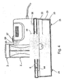
- the electrical drive unit 6, as also best seen in Fig. 2 includes a housing 60 of substantially cubical configuration, except that two recesses 61, 62 are formed in the upper portions of two opposed side walls to the top wall. Recesses 61, 62 are configured to serve as hand grips to facilitate grasping the electrical drive unit when applied to, or removed from, housing 2.
- housing 60 facing feed chute 3 is formed with a curved recess 63 conforming, to the curvature of the outer surface of the feed chute for firmly nesting the electrical drive unit with respect to the feed chute.
- the upper end of the curved, recessed portion 63 of housing 60 includes an opening 64 located to receive projection 33 of the feed chute 3.
- electrical drive unit 6 includes an electrical motor, schematically shown at 65, together with a mechanism, schematically shown at 66, for converting the rotary movement of the output shaft of the motor to a reciprocatory movement.
- Mechanism 66 is coupled to link 46 extending through slot 27 of the top wall 24 of housing 2, for reciprocating the cutter device 4 transversely across the outlet end 31 of feed chute 3.
- An on/off switch 67 is located on the top wall of electrical drive unit 6 for controlling the operation of the motor.
- electrical drive unit 6 further includes an interlock electrical switch 68 which normally disables on/off switch 67 from energizing the electrical motor.
- Interlock lock switch 68 is located so as to be engaged by projection 33 of feed chute 3, when the electrical drive unit is properly positioned in nesting contact with the feed chute, to enable the on/off switch 67 to energize the electrical motor.
- the bottom wall of housing 60 is formed with a pair of openings adapted to receive the upstanding pins 26 carried by the top wall 24 of housing 2.
- pins 26 are dimensioned so as to be receivable within the openings formed in the bottom wall of the electrical drive unit with a releasable friction fit.
- the foregoing construction permits the convenient disassembly of the various components of the appliance for purposes of cleaning, and reassembly for continued operation.
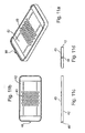
- Figs. 11a-11d illustrate the cutter member 42 as being a shredder member for shredding the food articles.
- Figs. 12a-12d illustrate another type of cutter member, generally designated 70, for cutting the food articles into longitudinally-extending sticks or strips, such as potato sticks or strips.
- cutter member 70 includes a mounting plate 71 having a thickness which is reduced along a mid-portion diagonal line 72 to define a reduced thickness in section 73 bordered on opposite sides by walls 74, 75 serving as continuations of the upper surface of main section of mounting plate 71.
- a first blade 76 is fixed to mounting plate 71 such that the cutting edge of the blade projects slightly past the diagonal wall 72.
- a group of spaced further blades 77 are fixed to the reduced-thickness section 73 of the mounting plate to extend perpendicularly to blade 76 and parallel to the path of movement of the cutter member 70 during its reciprocations.
- mounting plate 71 is formed with an axially-extending tab 78, corresponding to tab 48 of cutter member 42 in Figs. 9 and 11a , for reception within slot 47 of the cutter holder 41, as shown in Fig. 9 .
- the reduced-thickness section 73 of the mounting plate is formed with a curved recess 79 to facilitate finger-gripping the cutter member when applying it to or removing it from the cutter holder 41.
- blade 76 extends horizontally parallel to the removable top wall 24 of housing. 2, and blade 77 extends substantially vertically with respect to that wall, such that the reciprocations of the cutter member, during the operation of the appliance, will cut the food articles fed via the feed chute 3 into longitudinally-extending strips or sticks.
- Figs. 13a-13d illustrate another cutter member, generally designated 80, effective to cut the food articles into slices.
- Cutter member 80 includes a mounting plate 81 divided into two reduced-thickness sections 81a, 81b, separated at its mid-portion by a diagonally-extending strip 82.
- a cutter blade 83 is fixed to the mid-section 82, and is formed with a cutting edge 83a projecting slightly outwardly of the mid-section 82.
- the two end sections 81a, 81b, and the mid-section 82 are bordered on opposite sides by upstanding walls 84, 85, each formed with an in-turned flange 86, 87.
- mounting plate 81 is formed with an axially-extending; tab 88, corresponding to axial tab 78: in cutter member 70 of Fig. 12a , whereas the opposite end is formed with a curved recess 89, corresponding to curved recess 79 in cutter member 70 of Fig. 12a .
- cutter member 80 may be conveniently applied to the cutter holder 41 by merely finger-grasping the mounting plate 81 via finger gripping recess 89 and inserting tab 88 into slot 47 of the cutter holder, as described above with respect to Figs. 12a-12d . It will also be seen that when cutter member 80 is used, each reciprocation of the cutter member will cut-off a slice of the food article fed through the feed chute.
- Figs. 14a-14d illustrate a cutter member, therein generally designated 80', of substantially the same construction as cutter member 80 in Figs. 13a-13d , and therefore to facilitate to understanding, corresponding parts have been identified by the same reference numerals.
- Cutter member 80' illustrated in Figs. 14a-14d include two variations.
- the horizontal blade 83 includes two cutting edges 83a and 83b, such that using that cutter member produces a slice of the food article during each forward movement and also during each return movement of the cutter member.
- each insert 91a, 91b is of the same shape as its corresponding section of the mounting plate, and is of a thickness to decrease the distance between its upper surface and the cutting edge 83a, 83b, of the-cutting, blade 83, such that when the insert is used, it effectively reduces the thickness of the slice cut from the food article.
- the edge of insert 91b to overlie section 81b of the mounting plate is formed with a circular recess 98 corresponding to recess 88 of the mounting plate, to facilitate the application of the cutter member, when including the inserts, into the cutter holder as described above.
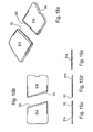
- Figs. 15a-15e more particularly illustrate the construction of each of the inserts 91a, 91b. It will be seen that their confronting edges 92, 93 are formed at a diagonal, and are also tapered. The construction is such that when cutting blade 83 is applied thereover, as shown particularly in Fig. 14a , they cooperate with the cutting edges 83a, 83b of the cutting blade to neatly cut a slice of the food article, not only during each forward reciprocation of the cutter member, but also during each backward reciprocation of the cutter member.
- the food articles to be cut may be manually introduced into feed chute 3 and manually pushed therethrough by pusher member 5, into engagement with the cutter device 4 within housing 2.
- the energisation of the electrical motor within the electrical drive unit 6 will reciprocate the cutter device 4 and cut the food article into the form as determined by the cutter member applied to holder 41 of the cutter device.
- the cuttings produced by the appliance are received within receptacle 23.
- Fig. 1 illustrates the appliance as including cutter member 42 ( Figs. 9 and 11a ) of the shredder type, such that the cuttings by the operation of the appliance will be in the form of shreddings.
- top wall 23 of the housing 2 is removed to expose cutter device 4, whereupon the cutter member within cutter holder 41 may be conveniently replaced according to the desired form of cuttings to be produced.
- cutter holder 70 illustrated in Figs. 12a-12d would be applied in place of the shredder plate 42.
- the arrangement for locking the removable top wall 24 in the upper end of housing member 21, including 21b in the housing member, opening 24b in the top wall peripheral flange 24a and the fiction fit between peripheral flange 24a and the thickened rim 21a of the housing member, permit convenient and secure arrangement of the removable top wall and convenient detachment thereof for cleaning purposes, cutter-member changing purposes, etc.
- the hand gripping recesses, 61, 62 of the electrical drive unit 6 facilitate the application and removal of the drive unit together with the top wall 24.
- the same operations may be performed for removing the cutter member in order to wash it after use, and/or for removing receptacle 23 containing the cuttings produced by the operation of the appliance.
- the provision of the removable liner 22 enables the interior of housing 2 also to be conveniently cleaned or washed.
Landscapes
- Forests & Forestry (AREA)
- Engineering & Computer Science (AREA)
- Mechanical Engineering (AREA)
- Life Sciences & Earth Sciences (AREA)
- Food-Manufacturing Devices (AREA)
- Crushing And Pulverization Processes (AREA)
- Confectionery (AREA)
- Noodles (AREA)
- Beans For Foods Or Fodder (AREA)
- Preparation Of Fruits And Vegetables (AREA)
- Processing Of Solid Wastes (AREA)
- Disintegrating Or Milling (AREA)
- Perforating, Stamping-Out Or Severing By Means Other Than Cutting (AREA)
Claims (16)
- Eine Lebensmittelverarbeitungsvorrichtung zum Schneiden von Lebensmitteln in eine gewünschte Form, Folgendes umfassend:ein Gehäuse (2), das eine abnehmbare obere Wand (24) einschließt;einen Zuführschacht (3), der von der oberen Wand (24) getragen wird und damit abnehmbar ist, wobei der Zuführschacht (3) ein Einlassende hat, das aus der oberen Wand (24) nach außen ragt, und ein Auslassende, das durch die obere Wand (24) in das Gehäuse (2) führt;ein Schubglied (5) zum Schieben von Lebensmitteln durch den Zuführschacht (3) in das Gehäuse (2);eine Schneidvorrichtung (4) in dem Gehäuse (2) und ausgerichtet mit dem Auslassende des Zuführschachts (3), wobei die Schneidvorrichtung (4) montiert ist für pendelnde Vorwärts- und Rückwärtsbewegungen quer über das Auslassende des Zuführschachts (3) zum Schneiden von Lebensmitteln, die dadurch zugeführt werden, in die gewünschte Form;und eine elektrische Antriebseinheit (6), die einen elektrischen Motor einschließt, welcher durch einen Ein-/Aus-Schalter zum Hin- und Herbewegen der Schneidvorrichtung (4) gesteuert wird, wobei die elektrische Antriebseinheit (6) bequem an dem Gehäuse (2) befestigt werden kann, um die Schneidvomchtung (4) hin- und herzubewegen, und von dem Gehäuse (2) entfernt werden kann, um die Reinigung der Schneidvorrichtung (4) zu erleichtern;wobei die elektrische Antriebseinheit (6) einen elektrischen Sperrschalter einschließt, der in Normalstellung die Antriebseinheit (6) deaktiviert, aber betätigt werden kann, um die Antriebseinheit (6) zu aktivieren; dadurch gekennzeichnet, dassder Zuführschacht (3) ein Betätigungselement seitlich davon einschließt, um den elektrischen Sperrschalter, und damit die Antriebseinheit (6), zu betätigen, wenn die Antriebseinheit (6) sich in ihrer korrekten Position der oberen Wand (24) des Gehäuses (2) befindet, und das Betätigungselement einen Stift (33) einschließt, der an dem Zuführschacht (3) befestigt ist und sich seitlich davon erstreckt, wobei der Stift (33) in einer Buchse (64) in der Seitenwand der elektrischen Antriebseinheit (6) aufgenommen werden kann, so dass der Stift, wenn er in der elektrischen Antriebseinheit (6) aufgenommen ist, auch die elektrische Antriebseinheit (6) genau auf der oberen Wand (24) des Gehäuses (2) anordnet.
- Die Vorrichtung gemäß Anspruch 1, worin:der Zuführschacht (3) von einer zylindrischen Anordnung ist und die Seite davon, die der elektrischen Antriebseinheit (6) gegenüberliegt, den sich seitlich erstreckenden Stift einschließt; die Seite der elektrischen Antriebseinheit (6), die mit der Buchse (64) ausgebildet ist, eine gekrümmte Vertiefung einschließt, die der Krümmung des Zuführschachts (3) entspricht;und der Boden der elektrischen Antriebseinheit (6) mit zwei weiteren Buchsen (64) zur Aufnahme von Stiften ausgestattet ist, die am entsprechenden Ende der oberen Wand (24) des Gehäuses (2) geformt sind, zur genauen Anordnung der elektrischen Antriebseinheit (6) im Verhältnis zu dem Zuführschacht (3) und der oberen Wand (24) des Gehäuses (2).
- Die Vorrichtung gemäß Anspruch 1, worin die abnehmbare obere Wand (24) mit einem abhängigen peripheren Flansch ausgebildet ist, der so bemessen ist, um das obere Ende des Gehäuses (2) mit einer Reibungspassung aufzunehmen, wobei ein Ende des Gehäuses (2) mit einem nach außen ragenden Stift ausgebildet ist, der geeignet ist, in einer Öffnung aufgenommen zu werden, die im entsprechenden Ende des abhängigen peripheren Flansches der abnehmbaren oberen Wand (24) geformt ist, um die obere Wand (24) fest am Gehäuse (2) zu verriegeln.
- Die Vorrichtung gemäß Anspruch 1, worin die elektrische Antriebseinheit (6) eine obere Wand (24) und gegenüberliegende Seitenwände einschließt, die mit Vertiefungen geformt sind, welche ausgebildet sind, um als Handgriffe zu dienen, die das Ergreifen der elektrischen Antriebseinheit (6) zur Anbringung oder Abnahme der elektrischen Antriebseinheit (6) in Bezug auf die obere Wand (24) des Gehäuses (2) erleichtern.
- Die Vorrichtung gemäß Anspruch 1, worin die Schneidvorrichtung (4) einen Abschneiderhalter einschließt, der mit der elektrischen Antriebseinheit (6) gekoppelt werden kann, um davon hin- und herbewegt zu werden, und ein Abschneiderglied, das abnehmbar von dem Abschneiderhalter getragen wird.
- Die Vorrichtung gemäß Anspruch 5, worin das Abschneiderglied Folgendes einschließt:eine erste Klinge, die sich quer über den Bewegungspfad des Abschneiderhalters während seiner Hin- und Herbewegungen erstreckt;und eine Gruppe beabstandeter weiterer Klingen, die sich rechtwinklig zu der ersten Klinge und parallel zu dem Bewegungspfad des Abschneiderhalters während seiner Hin- und Herbewegungen erstrecken, so dass das Abschneiderglied die Lebensmittel in sich in Längsrichtung erstreckende Streifen schneidet.
- Die Vorrichtung gemäß Anspruch 6, worin sich die erste Klinge im Wesentlichen horizontal parallel zu der abnehmbaren oberen Wand (24) des Gehäuses (2) erstreckt und sich die Gruppe beabstandeter weiterer Klingen im Wesentlichen vertikal zu der abnehmbaren oberen Wand (24) des Gehäuses (2) erstreckt.
- Die Vorrichtung gemäß Anspruch 5, worin das Abschneiderglied eine Klinge einschließt, die sich quer über den Bewegungspfad des Abschneiderhalters während seiner Hin- und Herbewegungen erstreckt;
wobei die Klinge eine Schneidkante an jeder ihrer gegenüberliegenden Enden hat, um eine Scheibe des Lebensmittels sowohl während der pendelnden Vorwärts- als auch während der Rückwärtsbewegungen der Sehneidvortichtung (4) abzuschneiden. - Die Vorrichtung gemäß Anspruch 5, worin das Abschneiderglied eine Zerkleinerungsplatte zum Zerkleinern der Lebensmittel einschließt.
- Die Vorrichtung gemäß Anspruch 1, worin die Schneidvorrichtung (4) einen Abschneiderhalter einschließt, der mit der elektrischen Antriebseinheit (6) gekoppelt werden kann, um davon hin- und herbewegt zu werden; und
worin die Vorrichtung weiter eine Vielzahl verschiedener Arten von Abschneidergliedem einschließt, die zum Schneiden der Lebensmittel in die gewünschte Form selektiv in dem Abschneiderhalter aufgenommen werden können. - Die Vorrichtung gemäß Anspruch 1, worin eine Art von Abschneiderglied, die selektiv in dem Abschneiderhalter aufgenommen werden kann, eine erste Klinge einschließt, welche sich quer über den Bewegungspfad des Abschneiderhalters während seiner Hin- und Herbewegungen erstreckt;
und eine Gruppe beabstandeter weiterer Klingen, die sich rechtwinklig zu der ersten Klinge und parallel zu dem Bewegungspfad des Abschneiderhalters während seiner Hin- und Herbewegungen erstrecken, so dass das Abschneiderglied die Lebensmittel in sich in Längsrichtung erstreckende Streifen schneidet. - Die Vorrichtung gemäß Anspruch 11, worin sich die erste Klinge im Wesentlichen horizontal parallel zu der abnehmbaren oberen Wand (24) des Gehäuses (2) erstreckt und sich die Gruppe beabstandeter weiterer Klingen im Wesentlichen vertikal zu der abnehmbaren oberen Wand (24) des Gehäuses (2) erstreckt.
- Die Vorrichtung gemäß Anspruch 10, worin eine Art von Abschneiderglied, die selektiv in dem Abschneiderhalter aufgenommen werden kann, eine Klinge einschließt, welche sich quer über den Bewegungspfad des Abschneiderhalters während seiner Hin- und Herbewegungen erstreckt;
wobei die Klinge eine Schneidkante an jeder ihrer gegenüberliegenden Enden hat, um eine Scheibe des Lebensmittels sowohl während der pendelnden Vorwärts- als auch während der Rückwärtsbewegungen der Schneidvorrichtung (4) abzuschneiden. - Die Vorrichtung gemäß Anspruch 10, worin eine Art von Abschneiderglied eine Zerkleinerungsplatte zum Zerkleinern der Lebensmittel einschließt.
- Die Vorrichtung gemäß Anspruch 10, worin eine Art von Abschneiderglied eine Klinge einschließt, welche sich quer über den Bewegungspfad des Abschneiderhalters während seiner Hin- und Herbewegungen erstreckt, wobei die Klinge mindestens eine Schneidkante zum Schneiden der Lebensmittel in Scheiben während jeder der Hin- und Herbewegungen des Abschneiderhalters hat.
- Die Vorrichtung gemäß Anspruch 1, worin die Vorrichtung weiter einen Behälter umfasst, der unter der Schneidvorrichtung (4) liegt und von dem Gehäuse (2) entfernt werden kann, zur Aufnahme und zum Entfernen der Lebensmittel, nachdem sie von der Schneidvorrichtung (4) geschnitten wurden.
Applications Claiming Priority (2)
| Application Number | Priority Date | Filing Date | Title |
|---|---|---|---|
| US11/647,253 US7543768B2 (en) | 2006-12-29 | 2006-12-29 | Food processor appliance for cutting food articles into desired forms |
| PCT/IB2007/004103 WO2008081293A2 (en) | 2006-12-29 | 2007-12-27 | Food processor appliance for cutting food articles- into desired forms |
Publications (2)
| Publication Number | Publication Date |
|---|---|
| EP2099345A2 EP2099345A2 (de) | 2009-09-16 |
| EP2099345B1 true EP2099345B1 (de) | 2011-02-09 |
Family
ID=39204823
Family Applications (1)
| Application Number | Title | Priority Date | Filing Date |
|---|---|---|---|
| EP20070859188 Not-in-force EP2099345B1 (de) | 2006-12-29 | 2007-12-27 | Mixervorrichtung zum schneiden von nahrungsmittelartikeln in gewünschte formen |
Country Status (7)
| Country | Link |
|---|---|
| US (1) | US7543768B2 (de) |
| EP (1) | EP2099345B1 (de) |
| CN (1) | CN101616623B (de) |
| AT (1) | ATE497713T1 (de) |
| CA (1) | CA2673827A1 (de) |
| DE (1) | DE602007012470D1 (de) |
| WO (1) | WO2008081293A2 (de) |
Families Citing this family (27)
| Publication number | Priority date | Publication date | Assignee | Title |
|---|---|---|---|---|
| US20080250943A1 (en) * | 2007-03-31 | 2008-10-16 | Hugues Francois Malandain | Systems and Methods for Dispensing Food |
| US20080308661A1 (en) * | 2007-06-11 | 2008-12-18 | Mah Pat Y | Linear food processor |
| JP2011511715A (ja) * | 2008-02-08 | 2011-04-14 | コンアグラ フーヅ ラム ウェストン インコーポレイテッド | 野菜をスライスするための装置および方法 |
| USD632139S1 (en) * | 2009-06-10 | 2011-02-08 | Cedomir Repac | Kitchen utensil |
| AU334922S (en) * | 2010-07-07 | 2011-02-01 | Dkb Household Uk Ltd | Food slicer |
| USD651483S1 (en) * | 2011-02-05 | 2012-01-03 | Progressive International Corporation | Mandoline slicer |
| USD650642S1 (en) * | 2011-02-25 | 2011-12-20 | Conair Corporation | Mandoline slicer |
| US8544781B2 (en) * | 2011-03-03 | 2013-10-01 | Dongguan Futai Electronic Co., Ltd. | Power shredder with individually removable components structure |
| USD730704S1 (en) | 2011-06-22 | 2015-06-02 | Genius Gmbh | Food cutting device |
| USD666881S1 (en) * | 2011-08-08 | 2012-09-11 | Telebrands Corp. | Mandolin slicer |
| FR2999899B1 (fr) * | 2012-12-21 | 2016-01-15 | Seb Sa | Appareil de decoupe d’aliments a mouvement alternatif avec commande de securite |
| FR2999898B1 (fr) * | 2012-12-21 | 2015-02-27 | Seb Sa | Appareil de decoupe d’aliments a mouvement alternatif avec recipient amovible lavable |
| USD718581S1 (en) * | 2013-11-21 | 2014-12-02 | Ontel Products Corporation | Spiral peeler |
| FR3022170B1 (fr) * | 2014-06-13 | 2016-07-15 | Philippe Bernede | Dispositif de decoupe des aliments |
| US20160106140A1 (en) * | 2014-10-21 | 2016-04-21 | Helen Of Troy Limited | Fruit cutting device with pusher |
| FR3036994B1 (fr) * | 2015-06-08 | 2017-12-01 | Seb Sa | Appareil de decoupe d'aliments ameliore |
| CN106313144A (zh) * | 2015-07-01 | 2017-01-11 | 东莞市欣能电器有限公司 | 一种用于食物切割设备的多功能可换刀盘 |
| CN106313145A (zh) * | 2015-07-01 | 2017-01-11 | 东莞市欣能电器有限公司 | 一种具有可拆卸刀盘座的往复式切割设备 |
| USD791531S1 (en) * | 2015-09-04 | 2017-07-11 | Strategic Exits LLC | Coffee grinder |
| WO2017205471A1 (en) | 2016-05-25 | 2017-11-30 | Sharkninja Operating Llc | Oscillating blade for food processor system |
| CN106073555A (zh) * | 2016-08-19 | 2016-11-09 | 宁波众海电器有限公司 | 一种多功能厨用刨刀 |
| CN114147776A (zh) * | 2018-08-10 | 2022-03-08 | 宁波金舜家居用品有限公司 | 一种食品切割器 |
| AU2019409988B2 (en) * | 2018-12-21 | 2025-08-14 | Breville Pty Limited | A handheld motorised food cutting device |
| USD949642S1 (en) | 2020-02-25 | 2022-04-26 | Allstar Marketing Group, Llp | Adjustable slicer |
| US11597116B1 (en) | 2021-09-14 | 2023-03-07 | Progressive International Corp. | Vertical slicer |
| CN114347124A (zh) * | 2022-02-21 | 2022-04-15 | 湖北全康智能科技有限公司 | 一种食材切割处理装置 |
| US12376605B2 (en) * | 2024-01-11 | 2025-08-05 | Guangdong Link Plus Technology Group Co., Ltd | Ice cream maker |
Family Cites Families (20)
| Publication number | Priority date | Publication date | Assignee | Title |
|---|---|---|---|---|
| US564829A (en) * | 1896-07-28 | Suspenders | ||
| USD250568S (en) | 1977-03-10 | 1978-12-19 | Kidde Consumer Durables Corp. | Food processor |
| FR2384476A1 (fr) | 1977-03-23 | 1978-10-20 | Allumettes Ste Indle Forestier | Dispositif de securite pour appareils de preparation d'aliments |
| US4113188A (en) | 1977-04-25 | 1978-09-12 | Kidde Consumer Durables Corp. | Food processor |
| US4216917A (en) * | 1978-11-13 | 1980-08-12 | Cuisinarts, Inc. | Safety interlock for the food pusher in a food processor |
| DE2922739C2 (de) * | 1979-06-05 | 1982-03-18 | Alfred 5561 Landscheid Börner | Frucht-Reibe |
| JPS6044744U (ja) | 1983-08-31 | 1985-03-29 | 鈴木 元 | 野菜類調理器 |
| DE3500495A1 (de) * | 1985-01-09 | 1986-07-10 | A. Börner GmbH, 5561 Landscheid | Kuechengeraet zum schneiden von gemuese, insbesondere kartoffeln in streifen |
| DE3637169C1 (de) * | 1986-10-31 | 1993-01-14 | Braun Ag | Kuechenmaschine zum Zubereiten von Nahrungsmitteln |
| US4928893A (en) | 1989-04-10 | 1990-05-29 | Robinson Knife Manufacturing Co., Inc. | Food processor |
| DE9110587U1 (de) * | 1991-08-27 | 1991-11-14 | Friesen, Walter, 4600 Dortmund | Gemüsehobel |
| US5445332A (en) | 1993-09-02 | 1995-08-29 | Kabushiki Kaisha Izumi Seiki Seisakusho | Food processor |
| USD366984S (en) | 1994-08-29 | 1996-02-13 | Airlux Electrical Co., Ltd. | Multi-food processor and juice extractor |
| USD368622S (en) | 1994-09-02 | 1996-04-09 | Kabushiki Kaisha Izumi Seiki Seisakusho | Food processor |
| USD369511S (en) | 1995-03-13 | 1996-05-07 | Tse-Hsiung Chen | Food processor |
| DE29914149U1 (de) * | 1999-08-12 | 1999-12-16 | Gottwald, Walter, 90579 Langenzenn | Käsereibe |
| CN2426277Y (zh) * | 2000-01-27 | 2001-04-11 | 上海伟隆机械制造厂 | 食品原料切割装置 |
| US6748853B1 (en) | 2000-09-13 | 2004-06-15 | Hamilton Beach/Proctor-Silex, Inc. | Food processing machine |
| FR2825043B1 (fr) * | 2001-05-28 | 2003-09-19 | Buyer De | Coupe-legumes manuel de securite |
| USD564829S1 (en) | 2007-06-29 | 2008-03-25 | Aac Trade Ltd. | Food processor |
-
2006
- 2006-12-29 US US11/647,253 patent/US7543768B2/en not_active Expired - Fee Related
-
2007
- 2007-12-27 AT AT07859188T patent/ATE497713T1/de not_active IP Right Cessation
- 2007-12-27 WO PCT/IB2007/004103 patent/WO2008081293A2/en not_active Ceased
- 2007-12-27 EP EP20070859188 patent/EP2099345B1/de not_active Not-in-force
- 2007-12-27 CA CA 2673827 patent/CA2673827A1/en not_active Abandoned
- 2007-12-27 CN CN2007800455823A patent/CN101616623B/zh not_active Expired - Fee Related
- 2007-12-27 DE DE200760012470 patent/DE602007012470D1/de active Active
Also Published As
| Publication number | Publication date |
|---|---|
| WO2008081293A3 (en) | 2009-03-12 |
| US7543768B2 (en) | 2009-06-09 |
| CA2673827A1 (en) | 2008-07-10 |
| CN101616623B (zh) | 2012-07-18 |
| ATE497713T1 (de) | 2011-02-15 |
| EP2099345A2 (de) | 2009-09-16 |
| US20080156204A1 (en) | 2008-07-03 |
| HK1133807A1 (en) | 2010-04-09 |
| WO2008081293A2 (en) | 2008-07-10 |
| CN101616623A (zh) | 2009-12-30 |
| DE602007012470D1 (de) | 2011-03-24 |
Similar Documents
| Publication | Publication Date | Title |
|---|---|---|
| US7543768B2 (en) | Food processor appliance for cutting food articles into desired forms | |
| CA2355225C (en) | Hand-held food processor | |
| US7690285B2 (en) | Manual safety vegetable cutter | |
| EP2533954B1 (de) | Handgegriffene vorrichtung zum schneiden von lebensmitteln | |
| EP1955628B1 (de) | Schneidegerät und Reibeisen für Lebensmittel | |
| US20100037787A1 (en) | Rotary food cutter with removable blade assembly | |
| CN101631653A (zh) | 蔬菜和水果切片机以及用于切片的方法 | |
| US20140047964A1 (en) | Food Slicer | |
| US20020174754A1 (en) | Safety manual vegetable cutter | |
| EP2701882B1 (de) | Vorrichtung zum schneiden von lebensmitteln | |
| WO2006099792A1 (en) | Food slicing device | |
| US20070095189A1 (en) | Combination food preparation device | |
| US11389985B2 (en) | Fry cutter and cuber | |
| HK1133807B (en) | Food processor appliance for cutting food articles into desired forms | |
| CN114918989A (zh) | 食物切割机 | |
| US5899133A (en) | Frozen hamburger patty separator | |
| HK1139023A (en) | Food processor appliance for cutting food articles- into desired forms | |
| CN217454051U (zh) | 食物切割机 | |
| US7451675B1 (en) | Power-operated cutting board | |
| US20080302893A1 (en) | Linear food processor | |
| KR20130080378A (ko) | 여러개의 모드를 갖는 다용도 슬라이서 | |
| KR20050031134A (ko) | 다이서 | |
| JP3022202U (ja) | 野菜等の調理器 | |
| KR20120031968A (ko) | 마늘의 꼭지 제거 기능 및 마늘을 일정한 간격으로 세절이 가능한 마늘 세절 장치 | |
| KR102094080B1 (ko) | 마늘 세절기 및 마늘 세절기에 적합하게 적용될 수 있는 칼날 설치구조 |
Legal Events
| Date | Code | Title | Description |
|---|---|---|---|
| PUAI | Public reference made under article 153(3) epc to a published international application that has entered the european phase |
Free format text: ORIGINAL CODE: 0009012 |
|
| 17P | Request for examination filed |
Effective date: 20090629 |
|
| AK | Designated contracting states |
Kind code of ref document: A2 Designated state(s): AT BE BG CH CY CZ DE DK EE ES FI FR GB GR HU IE IS IT LI LT LU LV MC MT NL PL PT RO SE SI SK TR |
|
| 17Q | First examination report despatched |
Effective date: 20091217 |
|
| DAX | Request for extension of the european patent (deleted) | ||
| REG | Reference to a national code |
Ref country code: HK Ref legal event code: DE Ref document number: 1133807 Country of ref document: HK |
|
| GRAP | Despatch of communication of intention to grant a patent |
Free format text: ORIGINAL CODE: EPIDOSNIGR1 |
|
| RTI1 | Title (correction) |
Free format text: FOOD PROCESSOR APPLIANCE FOR CUTTING FOOD ARTICLES INTO DESIRED FORMS |
|
| GRAS | Grant fee paid |
Free format text: ORIGINAL CODE: EPIDOSNIGR3 |
|
| GRAA | (expected) grant |
Free format text: ORIGINAL CODE: 0009210 |
|
| AK | Designated contracting states |
Kind code of ref document: B1 Designated state(s): AT BE BG CH CY CZ DE DK EE ES FI FR GB GR HU IE IS IT LI LT LU LV MC MT NL PL PT RO SE SI SK TR |
|
| REG | Reference to a national code |
Ref country code: GB Ref legal event code: FG4D |
|
| REG | Reference to a national code |
Ref country code: CH Ref legal event code: EP |
|
| REG | Reference to a national code |
Ref country code: IE Ref legal event code: FG4D |
|
| REF | Corresponds to: |
Ref document number: 602007012470 Country of ref document: DE Date of ref document: 20110324 Kind code of ref document: P |
|
| REG | Reference to a national code |
Ref country code: DE Ref legal event code: R096 Ref document number: 602007012470 Country of ref document: DE Effective date: 20110324 |
|
| REG | Reference to a national code |
Ref country code: HK Ref legal event code: GR Ref document number: 1133807 Country of ref document: HK |
|
| REG | Reference to a national code |
Ref country code: NL Ref legal event code: VDEP Effective date: 20110209 |
|
| LTIE | Lt: invalidation of european patent or patent extension |
Effective date: 20110209 |
|
| PG25 | Lapsed in a contracting state [announced via postgrant information from national office to epo] |
Ref country code: LV Free format text: LAPSE BECAUSE OF FAILURE TO SUBMIT A TRANSLATION OF THE DESCRIPTION OR TO PAY THE FEE WITHIN THE PRESCRIBED TIME-LIMIT Effective date: 20110209 Ref country code: ES Free format text: LAPSE BECAUSE OF FAILURE TO SUBMIT A TRANSLATION OF THE DESCRIPTION OR TO PAY THE FEE WITHIN THE PRESCRIBED TIME-LIMIT Effective date: 20110520 Ref country code: PT Free format text: LAPSE BECAUSE OF FAILURE TO SUBMIT A TRANSLATION OF THE DESCRIPTION OR TO PAY THE FEE WITHIN THE PRESCRIBED TIME-LIMIT Effective date: 20110609 Ref country code: SE Free format text: LAPSE BECAUSE OF FAILURE TO SUBMIT A TRANSLATION OF THE DESCRIPTION OR TO PAY THE FEE WITHIN THE PRESCRIBED TIME-LIMIT Effective date: 20110209 Ref country code: GR Free format text: LAPSE BECAUSE OF FAILURE TO SUBMIT A TRANSLATION OF THE DESCRIPTION OR TO PAY THE FEE WITHIN THE PRESCRIBED TIME-LIMIT Effective date: 20110510 Ref country code: LT Free format text: LAPSE BECAUSE OF FAILURE TO SUBMIT A TRANSLATION OF THE DESCRIPTION OR TO PAY THE FEE WITHIN THE PRESCRIBED TIME-LIMIT Effective date: 20110209 |
|
| PG25 | Lapsed in a contracting state [announced via postgrant information from national office to epo] |
Ref country code: AT Free format text: LAPSE BECAUSE OF FAILURE TO SUBMIT A TRANSLATION OF THE DESCRIPTION OR TO PAY THE FEE WITHIN THE PRESCRIBED TIME-LIMIT Effective date: 20110209 Ref country code: SI Free format text: LAPSE BECAUSE OF FAILURE TO SUBMIT A TRANSLATION OF THE DESCRIPTION OR TO PAY THE FEE WITHIN THE PRESCRIBED TIME-LIMIT Effective date: 20110209 Ref country code: BE Free format text: LAPSE BECAUSE OF FAILURE TO SUBMIT A TRANSLATION OF THE DESCRIPTION OR TO PAY THE FEE WITHIN THE PRESCRIBED TIME-LIMIT Effective date: 20110209 Ref country code: NL Free format text: LAPSE BECAUSE OF FAILURE TO SUBMIT A TRANSLATION OF THE DESCRIPTION OR TO PAY THE FEE WITHIN THE PRESCRIBED TIME-LIMIT Effective date: 20110209 Ref country code: CY Free format text: LAPSE BECAUSE OF FAILURE TO SUBMIT A TRANSLATION OF THE DESCRIPTION OR TO PAY THE FEE WITHIN THE PRESCRIBED TIME-LIMIT Effective date: 20110209 Ref country code: PL Free format text: LAPSE BECAUSE OF FAILURE TO SUBMIT A TRANSLATION OF THE DESCRIPTION OR TO PAY THE FEE WITHIN THE PRESCRIBED TIME-LIMIT Effective date: 20110209 Ref country code: FI Free format text: LAPSE BECAUSE OF FAILURE TO SUBMIT A TRANSLATION OF THE DESCRIPTION OR TO PAY THE FEE WITHIN THE PRESCRIBED TIME-LIMIT Effective date: 20110209 Ref country code: BG Free format text: LAPSE BECAUSE OF FAILURE TO SUBMIT A TRANSLATION OF THE DESCRIPTION OR TO PAY THE FEE WITHIN THE PRESCRIBED TIME-LIMIT Effective date: 20110509 |
|
| PG25 | Lapsed in a contracting state [announced via postgrant information from national office to epo] |
Ref country code: EE Free format text: LAPSE BECAUSE OF FAILURE TO SUBMIT A TRANSLATION OF THE DESCRIPTION OR TO PAY THE FEE WITHIN THE PRESCRIBED TIME-LIMIT Effective date: 20110209 Ref country code: DK Free format text: LAPSE BECAUSE OF FAILURE TO SUBMIT A TRANSLATION OF THE DESCRIPTION OR TO PAY THE FEE WITHIN THE PRESCRIBED TIME-LIMIT Effective date: 20110209 |
|
| PG25 | Lapsed in a contracting state [announced via postgrant information from national office to epo] |
Ref country code: CZ Free format text: LAPSE BECAUSE OF FAILURE TO SUBMIT A TRANSLATION OF THE DESCRIPTION OR TO PAY THE FEE WITHIN THE PRESCRIBED TIME-LIMIT Effective date: 20110209 Ref country code: SK Free format text: LAPSE BECAUSE OF FAILURE TO SUBMIT A TRANSLATION OF THE DESCRIPTION OR TO PAY THE FEE WITHIN THE PRESCRIBED TIME-LIMIT Effective date: 20110209 Ref country code: RO Free format text: LAPSE BECAUSE OF FAILURE TO SUBMIT A TRANSLATION OF THE DESCRIPTION OR TO PAY THE FEE WITHIN THE PRESCRIBED TIME-LIMIT Effective date: 20110209 |
|
| PLBE | No opposition filed within time limit |
Free format text: ORIGINAL CODE: 0009261 |
|
| STAA | Information on the status of an ep patent application or granted ep patent |
Free format text: STATUS: NO OPPOSITION FILED WITHIN TIME LIMIT |
|
| 26N | No opposition filed |
Effective date: 20111110 |
|
| REG | Reference to a national code |
Ref country code: DE Ref legal event code: R097 Ref document number: 602007012470 Country of ref document: DE Effective date: 20111110 |
|
| PG25 | Lapsed in a contracting state [announced via postgrant information from national office to epo] |
Ref country code: IT Free format text: LAPSE BECAUSE OF FAILURE TO SUBMIT A TRANSLATION OF THE DESCRIPTION OR TO PAY THE FEE WITHIN THE PRESCRIBED TIME-LIMIT Effective date: 20110209 |
|
| PG25 | Lapsed in a contracting state [announced via postgrant information from national office to epo] |
Ref country code: MC Free format text: LAPSE BECAUSE OF NON-PAYMENT OF DUE FEES Effective date: 20111231 |
|
| REG | Reference to a national code |
Ref country code: CH Ref legal event code: PL |
|
| REG | Reference to a national code |
Ref country code: FR Ref legal event code: ST Effective date: 20120831 |
|
| REG | Reference to a national code |
Ref country code: IE Ref legal event code: MM4A |
|
| PG25 | Lapsed in a contracting state [announced via postgrant information from national office to epo] |
Ref country code: LI Free format text: LAPSE BECAUSE OF NON-PAYMENT OF DUE FEES Effective date: 20111231 Ref country code: IE Free format text: LAPSE BECAUSE OF NON-PAYMENT OF DUE FEES Effective date: 20111227 Ref country code: CH Free format text: LAPSE BECAUSE OF NON-PAYMENT OF DUE FEES Effective date: 20111231 |
|
| PG25 | Lapsed in a contracting state [announced via postgrant information from national office to epo] |
Ref country code: MT Free format text: LAPSE BECAUSE OF FAILURE TO SUBMIT A TRANSLATION OF THE DESCRIPTION OR TO PAY THE FEE WITHIN THE PRESCRIBED TIME-LIMIT Effective date: 20110209 |
|
| PG25 | Lapsed in a contracting state [announced via postgrant information from national office to epo] |
Ref country code: FR Free format text: LAPSE BECAUSE OF NON-PAYMENT OF DUE FEES Effective date: 20120102 |
|
| PGFP | Annual fee paid to national office [announced via postgrant information from national office to epo] |
Ref country code: DE Payment date: 20121219 Year of fee payment: 6 |
|
| PG25 | Lapsed in a contracting state [announced via postgrant information from national office to epo] |
Ref country code: LU Free format text: LAPSE BECAUSE OF NON-PAYMENT OF DUE FEES Effective date: 20111227 |
|
| PG25 | Lapsed in a contracting state [announced via postgrant information from national office to epo] |
Ref country code: IS Free format text: LAPSE BECAUSE OF FAILURE TO SUBMIT A TRANSLATION OF THE DESCRIPTION OR TO PAY THE FEE WITHIN THE PRESCRIBED TIME-LIMIT Effective date: 20110209 |
|
| PG25 | Lapsed in a contracting state [announced via postgrant information from national office to epo] |
Ref country code: TR Free format text: LAPSE BECAUSE OF FAILURE TO SUBMIT A TRANSLATION OF THE DESCRIPTION OR TO PAY THE FEE WITHIN THE PRESCRIBED TIME-LIMIT Effective date: 20110209 |
|
| PG25 | Lapsed in a contracting state [announced via postgrant information from national office to epo] |
Ref country code: HU Free format text: LAPSE BECAUSE OF FAILURE TO SUBMIT A TRANSLATION OF THE DESCRIPTION OR TO PAY THE FEE WITHIN THE PRESCRIBED TIME-LIMIT Effective date: 20110209 |
|
| REG | Reference to a national code |
Ref country code: DE Ref legal event code: R119 Ref document number: 602007012470 Country of ref document: DE |
|
| REG | Reference to a national code |
Ref country code: DE Ref legal event code: R119 Ref document number: 602007012470 Country of ref document: DE Effective date: 20140701 |
|
| PG25 | Lapsed in a contracting state [announced via postgrant information from national office to epo] |
Ref country code: DE Free format text: LAPSE BECAUSE OF NON-PAYMENT OF DUE FEES Effective date: 20140701 |
|
| PGFP | Annual fee paid to national office [announced via postgrant information from national office to epo] |
Ref country code: GB Payment date: 20141219 Year of fee payment: 8 |
|
| GBPC | Gb: european patent ceased through non-payment of renewal fee |
Effective date: 20151227 |
|
| PG25 | Lapsed in a contracting state [announced via postgrant information from national office to epo] |
Ref country code: GB Free format text: LAPSE BECAUSE OF NON-PAYMENT OF DUE FEES Effective date: 20151227 |