EP2098387A2 - Cleaning vehicle - Google Patents
Cleaning vehicle Download PDFInfo
- Publication number
- EP2098387A2 EP2098387A2 EP09007334A EP09007334A EP2098387A2 EP 2098387 A2 EP2098387 A2 EP 2098387A2 EP 09007334 A EP09007334 A EP 09007334A EP 09007334 A EP09007334 A EP 09007334A EP 2098387 A2 EP2098387 A2 EP 2098387A2
- Authority
- EP
- European Patent Office
- Prior art keywords
- vehicle
- vehicle according
- axle
- wheels
- spring
- Prior art date
- Legal status (The legal status is an assumption and is not a legal conclusion. Google has not performed a legal analysis and makes no representation as to the accuracy of the status listed.)
- Granted
Links
- 238000004140 cleaning Methods 0.000 title claims description 10
- 239000000725 suspension Substances 0.000 claims abstract description 24
- 238000013016 damping Methods 0.000 claims description 12
- 230000000903 blocking effect Effects 0.000 claims description 5
- 230000006835 compression Effects 0.000 claims description 4
- 238000007906 compression Methods 0.000 claims description 4
- 238000006073 displacement reaction Methods 0.000 claims description 3
- 230000007257 malfunction Effects 0.000 claims description 3
- 238000005096 rolling process Methods 0.000 claims description 3
- 230000002787 reinforcement Effects 0.000 claims 1
- 238000007789 sealing Methods 0.000 claims 1
- BASFCYQUMIYNBI-UHFFFAOYSA-N platinum Chemical compound [Pt] BASFCYQUMIYNBI-UHFFFAOYSA-N 0.000 description 16
- 238000011161 development Methods 0.000 description 6
- 230000018109 developmental process Effects 0.000 description 6
- 241001417527 Pempheridae Species 0.000 description 4
- 230000005484 gravity Effects 0.000 description 4
- 239000002699 waste material Substances 0.000 description 4
- 230000001680 brushing effect Effects 0.000 description 3
- 238000010586 diagram Methods 0.000 description 3
- 230000035939 shock Effects 0.000 description 3
- 238000010408 sweeping Methods 0.000 description 3
- XLYOFNOQVPJJNP-UHFFFAOYSA-N water Substances O XLYOFNOQVPJJNP-UHFFFAOYSA-N 0.000 description 3
- 208000031968 Cadaver Diseases 0.000 description 2
- 241000287107 Passer Species 0.000 description 2
- 238000005406 washing Methods 0.000 description 2
- 235000003434 Sesamum indicum Nutrition 0.000 description 1
- 244000000231 Sesamum indicum Species 0.000 description 1
- 239000006096 absorbing agent Substances 0.000 description 1
- 238000012550 audit Methods 0.000 description 1
- 230000007423 decrease Effects 0.000 description 1
- 230000000593 degrading effect Effects 0.000 description 1
- 239000000428 dust Substances 0.000 description 1
- 235000021183 entrée Nutrition 0.000 description 1
- 239000004519 grease Substances 0.000 description 1
- 230000001771 impaired effect Effects 0.000 description 1
- 210000000056 organ Anatomy 0.000 description 1
- 230000000750 progressive effect Effects 0.000 description 1
- 238000011084 recovery Methods 0.000 description 1
Images
Classifications
-
- E—FIXED CONSTRUCTIONS
- E01—CONSTRUCTION OF ROADS, RAILWAYS, OR BRIDGES
- E01H—STREET CLEANING; CLEANING OF PERMANENT WAYS; CLEANING BEACHES; DISPERSING OR PREVENTING FOG IN GENERAL CLEANING STREET OR RAILWAY FURNITURE OR TUNNEL WALLS
- E01H1/00—Removing undesirable matter from roads or like surfaces, with or without moistening of the surface
- E01H1/02—Brushing apparatus, e.g. with auxiliary instruments for mechanically loosening dirt
- E01H1/05—Brushing apparatus, e.g. with auxiliary instruments for mechanically loosening dirt with driven brushes
- E01H1/053—Brushing apparatus, e.g. with auxiliary instruments for mechanically loosening dirt with driven brushes having vertical axes
-
- B—PERFORMING OPERATIONS; TRANSPORTING
- B60—VEHICLES IN GENERAL
- B60G—VEHICLE SUSPENSION ARRANGEMENTS
- B60G9/00—Resilient suspensions of a rigid axle or axle housing for two or more wheels
- B60G9/04—Resilient suspensions of a rigid axle or axle housing for two or more wheels the axle or housing not being pivotally mounted on the vehicle
-
- B—PERFORMING OPERATIONS; TRANSPORTING
- B60—VEHICLES IN GENERAL
- B60G—VEHICLE SUSPENSION ARRANGEMENTS
- B60G2200/00—Indexing codes relating to suspension types
- B60G2200/30—Rigid axle suspensions
-
- B—PERFORMING OPERATIONS; TRANSPORTING
- B60—VEHICLES IN GENERAL
- B60G—VEHICLE SUSPENSION ARRANGEMENTS
- B60G2200/00—Indexing codes relating to suspension types
- B60G2200/40—Indexing codes relating to the wheels in the suspensions
-
- B—PERFORMING OPERATIONS; TRANSPORTING
- B60—VEHICLES IN GENERAL
- B60G—VEHICLE SUSPENSION ARRANGEMENTS
- B60G2204/00—Indexing codes related to suspensions per se or to auxiliary parts
- B60G2204/10—Mounting of suspension elements
- B60G2204/12—Mounting of springs or dampers
- B60G2204/124—Mounting of coil springs
Definitions
- the present invention relates to a self-propelled vehicle for road sweeping-cleaning of the type comprising a driving cabin and able to circulate on automobile traffic lanes.
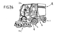
- Vehicles of this type already exist and the applicant has already obtained several patents perfecting these vehicles. They are mainly composed (see figure 26 ) of a frame (g) mounted on a front axle (h) and a rear axle (i) and carrying in the front a cockpit (j) accommodating a driver and possibly a passenger, and at the rear a waste collection tank (k). Said waste is collected and conveyed into the tank, by a brushing assembly (m) mounted at the front of the cabin, to a suction nozzle opening under the cabin and constituting the end of a suction duct connecting said nozzle to a suction turbine preferably located at the top of the tank and inside thereof. Additional functional elements such as watering ramp, residual water suction device, can be added between the brushing assembly and the suction nozzle.
- the Applicant has developed a new type of vehicle of this type from a new set of specifications imposing a priority to reduce the width of the vehicle while maintaining its height and maintaining excellent stability.
- the width imposed on the vehicle is to be less than 1.6 m to be able to circulate in lanes.
- the problem to be solved by the invention is to design a new narrow street sweeping-cleaning vehicle and retaining a cabinet for the driver, as well as a large capacity skip, vehicle can also be stable even when driving at high speed on the road.
- the various developments in terms of suspensions and a locking system of the rear axle contribute in combination to solve the stability problems caused by the narrowness of the vehicle and the height of the center of gravity.
- the first development of the invention relates more particularly to a locking device for the rear axle of said vehicle, the vehicle being a four-wheel steering vehicle.
- This type of vehicle usually drives at a reduced speed even when not in a cleaning situation.
- the plaintiff's goal is to design a cleaning vehicle that can travel at a speed of 80 km / hour on the road.
- Axle locks are known.
- the Applicant has developed a specific device described below.
- the vehicle comprises a system for controlling the angle of the rear wheels on the angle of the front wheels which drives a hydraulic block of the rear steering cylinders.
- the movement of the forward direction of a vehicle according to the invention is provided by mechanical and hydraulic elements (cylinders and bars) and the rear direction is slaved to the forward direction following the same principle with steering cylinders (101, 102) and bars or links (103, 104) associated with the rear axle (105).
- the electronic servo system slaving the angle of the rear wheels on the angle of the front wheels according to the steering angle of the front axle, in a manner known per se.
- this electronic system drives a hydraulic power unit of the rear steering cylinders (101, 102) just enough to obtain a corresponding steering of the axle In the rear, this system is very responsive because it continuously corrects the rear steering angle with respect to the steering angle.
- This mechanical locking device is a guarantee of security.
- the unrepresented angle sensors of the front wheels are deactivated by the lowering of the cylinder whose end of travel is detected by the sensors (120, 121).
- This low-pressure system represents an advantage in terms of safety, the locking capacity of the axle is in no way impaired (thanks to the spring) and avoids any rolling in four-wheel steering in case of hydraulic failure.
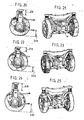
- FIG. 1 to 3 symbolically represent the plates (108) and (109) in the form of ellipses, but any other suitable form may be envisaged, in particular the preferred but non-limiting form of the upper plate shown in FIG. figure (11 ).
- This shape has two lateral openings (125, 126) so as to completely cover an overlap zone (127) around the trajectory (124) of the conical housing and of greater width than the upper diameter of said housing.
- the wiper seal (128) is arranged such that it completely protects this area (127).
- the second development of the invention relates to a suspension device for this cleaning-sweeping vehicle.
- This type of vehicle usually drives at a reduced speed even when not in a cleaning situation.
- a certain number of stability problems must be solved, especially in turns, which are accentuated if the vehicle is narrow.
- the Applicant has carried out a fine analysis of the suspension systems for narrow vehicles, and with a progressive center of gravity in use.
- the objective is therefore to provide a suspension system to best stabilize a vehicle with narrow lanes and high center of gravity.
- the invention which consists of a self-propelled vehicle for the cleaning of road surfaces, of the type mainly comprising a chassis mounted on a front wheel set and a rear wheel set and carrying a driving cabin to the before, a waste collection tank and its suction turbine connected to a suction tube passing through the frame and opening into a suction nozzle above the surface to be cleaned and behind a brushing assembly performing a function of sweeping the surface, said vehicle may further be equipped with means performing additional functions of cleaning the surface such as washing thereof, vehicle whose wheel trains comprise a spring suspension system, characterized in that that it comprises a system of connection between the chassis and an axle of a wheel train maintaining the vertical springs with a spacing modeled on the way of the vee vehicle.
- It consists mainly of two springs (c ') mounted between an axle (a') carrying the wheels (b ') and a frame not shown, and a suspension system of triangulation (d') mounted by a system to ball joint (e ') on the axle (a').
- the pivot point of the roll is on the median plane of the chassis.
- the lever arm dimension (x) and the spring stiffness (c ') determine the maximum roll angle at equivalent loads.
- the purpose sought by the applicant is to achieve a train with a spring suspension system, which reduces the width of the vehicle, while meeting all the constraints indicated above.
- This goal is achieved differently for the front and rear axle because of the constraints of presence of a driver's cab and a suction pipe near the front axle.
- a rear axle according to the invention comprises a suspension system (201) with springs, in connection with a transverse bar or a chassis cross member (202) and secondly with an axle (203) of wheels (204). ).
- the link between the chassis cross member (202) and the axle (203) is formed by two fixed offset frames (205), one end (206) of which is fixedly mounted on the axle (203) and between the two wheels. , and whose other end (207) is placed above a wheel and carries one end of the frame cross member through a spring (208) working in compression.
- the two offset frames (205) are placed symmetrically with respect to the median plane (P) of the chassis of the vehicle, and their shape and their dimensions make it possible to raise the springs and to place them in line with the wheels, while allowing to reduce the wheel spacing from a standard design and maintain the dimension (x) at the value selected by the roll calculation. (See Figures 5, 6 and 8 ).
- the spring device is completed by two rubber stops (210) mounted inside each of the springs to limit the vertical displacement of the cross member (202) in the event of impact, while playing a role in damping. .
- the force applied to the suspension spring is proportional to the dimension (x) and determines the arrow ( figure 8 ).
- shock absorbers determines the speed with which the pendulum movements of the body will be contained.
- the rear axle according to the invention also comprises a damping device consisting of two damping cylinders (211), each mounted vertically, between firstly bearings (226) of the chassis cross member (202) and secondly one of the offset frames (205), on the example of the figure 18 .
- a damping device consisting of two damping cylinders (211), each mounted vertically, between firstly bearings (226) of the chassis cross member (202) and secondly one of the offset frames (205), on the example of the figure 18 .
- the spacing of the two jacks can also be maintained by a horizontal bar (209) as on the figure 6 .
- the dimension (x) being identical to the half-spacing of the wheels instead of being significantly lower as in the standard design, said dimension requires less stiffness and a lower damping capacity, vehicle weight equivalent, which reduces the dimensions of springs and dampers.
- the spacing of the springs (2x) is modeled on the vehicle track (that is to say that the value 2x is greater than the spacing of the wheels) or substantially equal to the z-spacing of said wheels, to reduce the effort on the springs, like the important spacing of the dampers makes it possible to stabilize and to damp more quickly the box.
- the rear axle according to the invention is furthermore suspended by a suspension assembly (212) formed on the one hand by two lower guide rods (213) mounted under the axle (203) by pivots (215) and pivotable in a plane parallel to the frame and on the other hand an upper triangle (214), formed of two V-links (214), and mounted by a pivot system (216) under the horizontal bar (209) of the suspension system.
- a suspension assembly formed on the one hand by two lower guide rods (213) mounted under the axle (203) by pivots (215) and pivotable in a plane parallel to the frame and on the other hand an upper triangle (214), formed of two V-links (214), and mounted by a pivot system (216) under the horizontal bar (209) of the suspension system.
- the lower connecting rods (213) absorb the longitudinal force of the vehicle related to the damping, and allow the vertical movement of the axle by the pivots (215).
- the upper triangle (214) makes it possible to cash the lateral forces of the vehicle and also makes it possible to cash the vertical displacements of the axle by the pivot (216).
- the damping device comprises as before two damping cylinders (211), each mounted vertically between the upper cabin and the offset structures (205).
- the suspension assembly (212) is not modified because the upper triangle (214) does not interfere with the passage of the wheels.
- the driver's cab not shown is positioned above the wheels.
- the springs are split and arranged in pairs on the front and the back of each wheel, in a lowered position relative to the top of a wheel.
- a pivoting structure (218) mounted on the central pivot (219) of the axle comprises two arms (218a and 218b) arranged parallel to the rolling plane of a wheel and inside thereof.
- Each of the arms having its ends curved at 90 ° and each carrying a spring, so that each pair of springs (220 and 221) can pivot in a horizontal plane around a wheel during each steering operation.
- Each spring (220 and 221) is mounted in compression between a plate (222, 223) integral with one end of an arm (218a, 218b) and the underside of the unrepresented chassis of the vehicle, and can be equipped as before of a stop (210) inner rubber.
- This disposition of the springs makes it possible to obtain a large spring center distance without occupying the space above the wheel and makes it possible to lower the cabin and thus to reduce the height of the vehicle body.
- damping cylinders (211) are deported to allow steering wheels, they are provided between the underside of the frame and a lug (224 or 225) fixed under one of the plates (222 or 223) of each pivoting structure (218).
- the suspension assembly (212) is not modified.
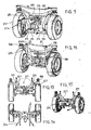
- FIGS. 18 to 25 show some examples of situation of a rear axle according to the invention that can occur during the work of the vehicle that is equipped, the arrows (229) and (228) show the amplitudes of damping and springs.
- the Figures 24 and 25 show the relaxation movement of the damping rods after a shock to the vehicle in figure 22 and 23 .
- a vehicle whose axles are equipped with an axle locking device which is the subject of the present application and which are furthermore equipped with the suspension systems described may have a width of less than 1.60 m a driving cabin accommodating a driver, a rear body as high as the cab to maintain good pickup capability, good stability even at high speed, and can drive safely both at low work speeds and at higher speeds on the road.
- these equipment can also, and conversely, be provided on larger vehicles whose swept surface area and / or stability is desired and, if desired, to reduce the height of the tank to an equal volume.
Landscapes
- Engineering & Computer Science (AREA)
- Architecture (AREA)
- Civil Engineering (AREA)
- Structural Engineering (AREA)
- Mechanical Engineering (AREA)
- Vehicle Body Suspensions (AREA)
- Cleaning Of Streets, Tracks, Or Beaches (AREA)
- Brushes (AREA)
- Vehicle Cleaning, Maintenance, Repair, Refitting, And Outriggers (AREA)
Abstract
Description
La présente invention concerne un véhicule automoteur pour le balayage-nettoyage de voirie du type comportant une cabine de pilotage et pouvant circuler sur des voies de circulation automobile.The present invention relates to a self-propelled vehicle for road sweeping-cleaning of the type comprising a driving cabin and able to circulate on automobile traffic lanes.
Des véhicules de ce type existent déjà et la demanderesse a déjà obtenus plusieurs brevets perfectionnant ces véhicules. Ils se composent principalement (voir
La demanderesse a développé un nouveau modèle de véhicule de ce type à partir d'un nouveau cahier des charges imposant de réduire en priorité la largeur du véhicule tout maintenant sa hauteur et en lui conservant une excellente stabilité.The Applicant has developed a new type of vehicle of this type from a new set of specifications imposing a priority to reduce the width of the vehicle while maintaining its height and maintaining excellent stability.
A titre indicatif la largeur imposée au véhicule est d'être inférieure à 1,6 m pour pouvoir circuler dans des ruelles.As an indication, the width imposed on the vehicle is to be less than 1.6 m to be able to circulate in lanes.
Le problème à résoudre par l'invention est de concevoir un nouveau véhicule de balayage-nettoyage de voirie étroit et conservant une cabinet pour le conducteur, ainsi qu'une benne de grande capacité, véhicule pouvant en outre être stable même en roulant à vitesse élevée sur route. Les différents développements au niveau des suspensions et d'un système de blocage de l'essieu arrière contribuent en combinaisons à résoudre les problèmes de stabilité engendrés par l'étroitesse du véhicule et la hauteur du centre de gravité.The problem to be solved by the invention is to design a new narrow street sweeping-cleaning vehicle and retaining a cabinet for the driver, as well as a large capacity skip, vehicle can also be stable even when driving at high speed on the road. The various developments in terms of suspensions and a locking system of the rear axle contribute in combination to solve the stability problems caused by the narrowness of the vehicle and the height of the center of gravity.
On comprendra mieux l'invention et les problèmes qu'elle résout grâce à la description ci-après et les figures annexées.The invention and the problems which it solves will be better understood from the following description and the appended figures.
Le premier développement de l'invention concerne plus particulièrement un dispositif de blocage pour l'essieu arrière dudit véhicule, le véhicule étant un véhicule à quatre roues directrices.The first development of the invention relates more particularly to a locking device for the rear axle of said vehicle, the vehicle being a four-wheel steering vehicle.
Ce type de véhicule roule habituellement à vitesse réduite, même lorsqu'il n'est pas en situation de nettoyage.This type of vehicle usually drives at a reduced speed even when not in a cleaning situation.
La demanderesse s'est fixée pour objectif de concevoir un véhicule de nettoyage pouvant rouler à la vitesse de 80 km/heure sur route.The plaintiff's goal is to design a cleaning vehicle that can travel at a speed of 80 km / hour on the road.
Il est connu d'équiper les balayeuses roulant à vitesse réduite de quatre roues directrices leur conférant un rayon de braquage plus court que celui des balayeuses à deux roues directrices, et leur permettant d'évoluer dans des ruelles étroites et de contourner au plus près le mobilier urbain. Cet équipement rend le véhicule très maniable à faible vitesse, lors d'une phase de travail, mais constitue un risque et un point critique en terme de stabilité au-dessus d'un certain seuil de vitesse.It is known to equip sweepers at low speeds with four steering wheels giving them a shorter turning radius than that of two-wheel steering sweepers, and allowing them to move in narrow streets and to bypass the closest urban furniture. This equipment makes the vehicle very maneuverable at low speed, during a work phase, but constitutes a risk and a critical point in terms of stability above a certain speed threshold.
La solution retenue par la demanderesse est de définir deux modes de fonctionnement, à savoir :
- un mode travail pour lequel la vitesse du véhicule est inférieure à 25 km/heure privilégiant la maniabilité avec l'utilisation de quatre roues directrices,
- un mode route pour lequel la vitesse du véhicule est supérieure à 25 km/heure, avec les roues avant directrices et l'essieu arrière aligné et bloqué.
- a working mode for which the speed of the vehicle is less than 25 km / hour privileging the handling with the use of four steering wheels,
- a road mode for which the vehicle speed is greater than 25 km / hour, with the front wheels steering and the rear axle aligned and locked.
Des dispositifs de blocage d'essieu sont connus. La demanderesse a développé un dispositif spécifique décrit ci-après.Axle locks are known. The Applicant has developed a specific device described below.
Principalement, le premier développement de l'invention consiste en un véhicule de nettoyage de voirie avec un châssis portant une cabine de pilotage et équipé de quatre roues directrices, le mouvement de la direction avant du véhicule étant assuré par des éléments mécaniques et hydrauliques (vérins et barres) et la direction arrière étant asservie à la direction avant suivant le même principe avec des vérins de direction et des barres ou biellettes associées à l'essieu arrière, caractérisé en ce qu'il comporte un dispositif de blocage mécanique de l'essieu arrière formé d'une interface mécanique composée d'une platine inférieure, pivotante et d'une platine supérieure fixe, et d'un vérin de blocage vertical combiné à un ressort et équipé en sous face d'un joint réalisant l'étanchéité entre les deux interfaces de telle sorte que :
- lorsque le véhicule est en mode travail, la pression hydraulique présente dans le vérin de blocage s'oppose à l'effort du ressort, le piston du vérin étant en position haute, et la platine reliant les barres de direction pouvant alors pivoter,
- lorsque lé véhicule est en mode route, le vérin de blocage n'est plus alimenté en puissance hydraulique et lorsque les roues avant et arrières sont alignées, la tête du piston traverse un logement de la platine supérieure et se bloque dans un logement conique de la platine inférieure ce qui entraîne le blocage de l'essieu arrière.
- when the vehicle is in working mode, the hydraulic pressure present in the locking cylinder opposes the force of the spring, the cylinder piston being in the up position, and the plate connecting the steering rods can then pivot,
- when the vehicle is in road mode, the locking cylinder is no longer supplied with hydraulic power and when the front and rear wheels are aligned, the piston head passes through a housing of the upper plate and locks in a conical housing of the bottom plate which causes the locking of the rear axle.
Préférentiellement, le véhicule comporte un système d'asservissement de l'angle des roues arrières sur l'angle des roues avant qui pilote un bloc hydraulique des vérins de direction arrière.Preferably, the vehicle comprises a system for controlling the angle of the rear wheels on the angle of the front wheels which drives a hydraulic block of the rear steering cylinders.
En outre et de façon préférentielle, on prévoit qu'en cas de dysfonctionnement hydraulique le vérin de blocage est automatiquement désactivé.In addition and preferably, it is expected that in case of hydraulic malfunction blocking cylinder is automatically disabled.
On comprendra mieux ce premier développement de l'invention à l'aide de la description ci-après faite en référence aux figures annexées suivantes :
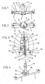
- la
figure 1 est un schéma de principe du système de blocage selon l'invention équipant un essieu arrière en vue de face, - la
figure 2 est une vue de dessus du schéma de principe de lafigure 1 , - la
figure 3 représente le détail référencé A sur lafigure 1 , - la
figure 4 représente en perspective le montage du vérin de blocage sur une platine fixe de l'interface de blocage selon un mode de réalisation préféré.
- the
figure 1 is a block diagram of the locking system according to the invention equipping a rear axle in front view, - the
figure 2 is a top view of the schematic diagram of thefigure 1 , - the
figure 3 represents the detail referenced A on thefigure 1 , - the
figure 4 represents in perspective the mounting of the locking cylinder on a fixed plate of the locking interface according to a preferred embodiment.
De façon classique, le mouvement de la direction avant d'un véhicule selon l'invention est assuré par des éléments mécaniques et hydrauliques (vérins et barres) et la direction arrière est asservie à la direction avant suivant le même principe avec des vérins de direction (101, 102) et des barres ou biellettes (103, 104) associées à l'essieu arrière (105).Conventionally, the movement of the forward direction of a vehicle according to the invention is provided by mechanical and hydraulic elements (cylinders and bars) and the rear direction is slaved to the forward direction following the same principle with steering cylinders (101, 102) and bars or links (103, 104) associated with the rear axle (105).
Afin de sécuriser le comportement routier à vitesse supérieure à 25 km/heure, il a été développé :
- un système permettant de réaliser un châssis quatre roues directrices sans liaison mécanique avant/arrière en raison du manque de place due à la compacité du véhicule ; il s'agit d'un système électronique permettant l'asservissement de l'arrière sur l'avant, et se devant d'être très réactif, en outre, il doit permettre de passer du mode route au mode travail et inversement en toute sécurité et en déclenchant un système de blocage (106) mécanique de l'essieu arrière.
- un système de blocage mécanique (106) fonctionnant dans tous les cas de figure, y compris en cas de défaillance du système d'asservissement.
- a system for producing a four-wheel steering chassis without mechanical linkage front / rear due to lack of space due to the compactness of the vehicle; it is an electronic system allowing the servo of the rear on the front, and having to be very reactive, in addition, it must allow to go from the road mode to the work mode and conversely in complete safety and triggering a mechanical locking system (106) of the rear axle.
- a mechanical locking system (106) operating in all cases, including in case of failure of the servo system.
Le système de blocage mécanique (106) présenté sur les figures se compose de :
- une interface mécanique (107) composée d'une platine inférieure (108) horizontale pivotante dans un plan horizontal, et surmontée d'une platine supérieure horizontale (109) et fixe. Les vérins (101) et (102) sont fixés d'une part à l'essieu arrière et d'autre part à la platine supérieure fixée sous un vérin de blocage (116) décrit plus loin. Cette platine supérieure fixe (109) est traversée par un logement cylindrique vertical (110) positionné dans l'axe (122) d'un piston (114) du vérin de blocage. La platine inférieure (108) est rendue mobile en rotation autour d'un axe vertical (123) sous l'action des vérins (101, 102) et barres (103, 104) et elle comporte un logement conique (111) traversant et décentré par rapport audit axe (123). Le dit alésage conique (111) décrit, au cours du mouvement de la platine inférieure (108), une trajectoire en arc de cercle (124) de part et d'autre d'une position médiane où il se trouve aligné avec l'axe du logement cylindrique (110). Le logement conique débouche de part et d'autre de la platine mobile et son diamètre supérieur et au moins égal au diamètre du logement cylindrique (110) et va en diminuant vers le bas,
- un vérin de blocage (116) dont le corps (112) alimenté hydrauliquement par son entrée (113), est fixé sur la platine supérieure (109) de sorte que le piston (114) soit disposé verticalement et que la tête (115) tronconique dudit piston puisse se déplacer en translation dans les logements (110 et 111). Les dimensions de la tête (115) sont prévues pour que celle-ci puisse descendre et pénétrer dans le logement conique (111) et s'y bloquer en position basse,
- un ressort (117) comprimé en position travail en dessous d'une vitesse prédéterminée (V < 25 km/heure par exemple) entre l'extrémité du piston (114) et une butée ou coffret (118) et exerçant sur celle-ci une force verticale (119) dirigée vers le bas,
- un joint racleur (128) annulaire disposé à la surface de contact entre la platine fixe et la platine mobile dont la fonction est d'empêcher la poussière et la graisse d'obstruer le logement conique (111), ce qui pourrait perturber le mouvement de la tête (115),
- au moins un capteur, et de préférence deux capteurs fin de course (120, 121) disposés sur le corps du vérin de blocage et détectant la position basse du piston (114) et en outre la position haute pour sécuriser le système en cas de défaillance de l'un deux.
- a mechanical interface (107) consisting of a horizontal lower platen (108) pivoting in a horizontal plane, and surmounted by a horizontal upper platen (109) and fixed. The cylinders (101) and (102) are fixed on the one hand to the rear axle and on the other hand to the upper plate fixed under a locking cylinder (116) described below. This fixed upper plate (109) is traversed by a vertical cylindrical housing (110) positioned in the axis (122) of a piston (114) of the locking cylinder. The bottom plate (108) is rotated about a vertical axis (123) under the action of the cylinders (101, 102) and bars (103, 104) and has a conical housing (111) passing through and off-center with respect to said axis (123). Said conical bore (111) describes, during the movement of the lower plate (108), an arcuate trajectory (124) on either side of a median position where it is aligned with the axis cylindrical housing (110). The conical housing opens on either side of the movable plate and its greater diameter and at least equal to the diameter of the cylindrical housing (110) and decreases downwardly,
- a locking cylinder (116) whose body (112) hydraulically fed by its inlet (113) is fixed on the upper plate (109) so that the piston (114) is arranged vertically and the frustoconical head (115) said piston can move in translation in the housings (110 and 111). The dimensions of the head (115) are designed so that it can descend and penetrate into the conical housing (111) and lock in the low position,
- a spring (117) compressed in working position below a predetermined speed (V <25 km / hour for example) between the end of the piston (114) and a stop or box (118) and exerting on it a vertical force (119) directed downwards,
- an annular scraper ring (128) disposed at the contact surface between the fixed platen and the movable platen, the function of which is to prevent dust and grease from clogging the conical housing (111), which could disturb the movement of the head (115),
- at least one sensor, and preferably two limit sensors (120, 121) disposed on the body of the locking cylinder and detecting the low position of the piston (114) and further the up position to secure the system in case of failure one of two.
Le dispositif de blocage fonctionne comme suit :
- Lorsque le véhicule est en mode travail, pour réaliser ses fonctions de balayage lavage et autres, les quatre roues sont directrices ; la pression hydraulique présente dans le vérin de blocage (116) s'oppose à l'effort du ressort (117), le piston (114) est en position haute. La platine inférieure reliant les barres de direction (103, 104) peut pivoter librement sous l'action des vérins hydrauliques pris en points fixes sur l'essieu et la platine fixe.
- When the vehicle is in working mode, to perform its washing and other sweeping functions, the four wheels are steered; the hydraulic pressure present in the locking cylinder (116) opposes the force of the spring (117), the piston (114) is in the up position. The lower plate connecting the steering rods (103, 104) can rotate freely under the action of the hydraulic cylinders taken in fixed points on the axle and fixed plate.
Le système électronique d'asservissement, asservit l'angle des roues arrière sur l'angle des roues avant en fonction de l'angle de braquage de l'essieu avant, de façon connue en soi. En plus, ce système électronique pilote un bloc hydraulique d'alimentation des vérins de direction arrière (101, 102) juste suffisamment de manière à obtenir un braquage correspondant de l'essieu arrière, ce système est très réactif car corrige en continu l'angle de braquage arrière par rapport à l'angle de braquage avant.The electronic servo system, slaving the angle of the rear wheels on the angle of the front wheels according to the steering angle of the front axle, in a manner known per se. In addition, this electronic system drives a hydraulic power unit of the rear steering cylinders (101, 102) just enough to obtain a corresponding steering of the axle In the rear, this system is very responsive because it continuously corrects the rear steering angle with respect to the steering angle.
Lorsque le conducteur du véhicule décide de passer en mode route (donc au-dessus de la vitesse V prédéterminée), il attend que des capteurs d'angles non représentés et placés sur les roues signalent que les roues sont alignées avec l'axe du véhicule, puis il déclenche le vérin de blocage (116) en coupant son alimentation hydraulique (113). La tête (115) du piston descend et se bloque dans le logement conique (111) provoquant le blocage de l'essieu arrière.When the driver of the vehicle decides to go into road mode (therefore above the predetermined speed V), he waits for unrepresented angle sensors and placed on the wheels to signal that the wheels are aligned with the axis of the vehicle , then it triggers the locking cylinder (116) by cutting off its hydraulic supply (113). The piston head (115) descends and locks in the conical housing (111) causing the rear axle to lock.
Lorsque le conducteur décide de repasser au mode travail, il ralentit le véhicule et lorsque celui-ci roule en dessous de la vitesse V, il alimente à nouveau le vérin de blocage pour provoquer la remontée du piston et débloquer l'essieu arrière.When the driver decides to return to working mode, he slows the vehicle and when it rolls below the speed V, it feeds again the locking cylinder to cause the rise of the piston and unlock the rear axle.
En cas de dysfonctionnement hydraulique, l'entrée (113) est fermée et automatiquement le vérin de blocage (116) n'est plus alimenté en puissance hydraulique, c'est donc le ressort (117) qui agit seul. Le piston descend alors au contact de la platine inférieure dès que les roues sont alignées et le conducteur ne peut plus passer en mode travail.In the event of a hydraulic malfunction, the inlet (113) is closed and automatically the blocking cylinder (116) is no longer supplied with hydraulic power, so the spring (117) acts alone. The piston then descends in contact with the lower platen as soon as the wheels are aligned and the driver can no longer go into work mode.
Ce dispositif mécanique de blocage est un gage de sécurité. En outre, les capteurs d'angle non représentés des roues avant sont désactivés par la descente du vérin dont la fin de course est détectée par les capteurs (120, 121).This mechanical locking device is a guarantee of security. In addition, the unrepresented angle sensors of the front wheels are deactivated by the lowering of the cylinder whose end of travel is detected by the sensors (120, 121).
Ce système à fonctionnement par manque de pression, représente un avantage en terme de sécurité, la capacité de blocage de l'essieu n'est en rien altérée (grâce au ressort) et évite tout roulage en quatre roues directrices en cas de panne hydraulique.This low-pressure system represents an advantage in terms of safety, the locking capacity of the axle is in no way impaired (thanks to the spring) and avoids any rolling in four-wheel steering in case of hydraulic failure.
Les
Le deuxième développement de l'invention concerne un dispositif de suspension pour ce véhicule de nettoyage-balayage.The second development of the invention relates to a suspension device for this cleaning-sweeping vehicle.
Ce type de véhicule roule habituellement à vitesse réduite même lorsqu'il n'est pas en situation de nettoyage. Afin de permettre une vitesse de circulation plus élevée, de l'ordre de 80 Km/h sur route, il faut résoudre un certain nombre de problèmes de stabilité surtout dans les virages, problèmes accentués si le véhicule est étroit.This type of vehicle usually drives at a reduced speed even when not in a cleaning situation. In order to allow a higher speed of traffic, of the order of 80 km / h on the road, a certain number of stability problems must be solved, especially in turns, which are accentuated if the vehicle is narrow.
Parmi les causes des différents problèmes de stabilité engendrés, on note en particulier :
- évolution du centre de gravité avec l'utilisation (en fonction de l'état de remplissage de la benne de récupération),
- remous ou mouvements dans le volume d'eau quand le véhicule est transformé en laveuse,
- étroitesse de la machine (à titre indicatif : voie inférieure à 1,6 m pour passer dans des ruelles),
- hauteur du véhicule pour avoir une capacité de ramassage maximale,
- déport limité des ressorts amortisseurs en raison du gabarit de la machine,
- espace disponible réduit autour des roues pour la réalisation d'une suspension efficace (concept de véhicule extra compact, c'est-à-dire dans lequel tous les organes mécaniques et moteurs sont rapprochés le plus possible les uns des autres sans perte de place),
- problèmes supplémentaires sur l'essieu avant en raison de la présence de la cabine de pilotage au-dessus des roues et de l'emplacement du tuyau d'aspiration entre les roues.
- evolution of the center of gravity with the use (depending on the state of filling of the recovery bucket),
- swirl or movement in the volume of water when the vehicle is converted into a washer,
- narrowness of the machine (for information: lane less than 1.6 m to pass in alleys),
- vehicle height for maximum pickup capacity,
- limited offset damping springs due to the machine template,
- reduced space available around the wheels for the realization of an effective suspension (concept of extra compact vehicle, that is to say in which all the mechanical and motor components are brought closer together as much as possible without loss of space) ,
- additional problems on the front axle due to the presence of the cockpit over the wheels and the location of the suction pipe between the wheels.
Tous ces points font qu'une balayeuse à déplacement rapide est instable.All of these points make a fast-moving sweeper unstable.
Afin de concevoir un véhicule stable et évoluant en toute sécurité, la demanderesse a réalisé une analyse fine des systèmes de suspension pour véhicule étroit, et à centre de gravité évolutif en cours d'utilisation.In order to design a stable and safely evolving vehicle, the Applicant has carried out a fine analysis of the suspension systems for narrow vehicles, and with a progressive center of gravity in use.
A partir des concepts existants et de l'environnement, il a fallu développer une liaison au sol spécifique pour la balayeuse selon l'invention.From the existing concepts and from the environment, it was necessary to develop a specific ground connection for the sweeper according to the invention.
L'objectif est donc de réaliser un système de suspension permettant de stabiliser au mieux un véhicule aux voies étroites et au centre de gravité élevé.The objective is therefore to provide a suspension system to best stabilize a vehicle with narrow lanes and high center of gravity.
Il faut donc développer un système qui puisse réaliser cet objectif dans un encombrement réduit, sans dégrader les capacités directionnelles et le confort de roulage du véhicule tout en améliorant sa tenue de route.We must develop a system that can achieve this goal in a small footprint, without degrading the directional capabilities and ride comfort of the vehicle while improving its handling.
Cet objectif est atteint par l'invention qui consiste en un véhicule automoteur pour le nettoyage de surfaces de voiries, du type comportant principalement un châssis monté sur un train de roues avant et un train de roues arrière et portant une cabine de conduite à l'avant, une cuve de collecte des déchets et sa turbine d'aspiration reliée à un tube d'aspiration traversant le châssis et débouchant dans une buse d'aspiration au-dessus de la surface à nettoyer et derrière un ensemble de brossage réalisant une fonction de balayage de la surface, ledit véhicule pouvant en outre être équipé de moyens réalisant des fonctions supplémentaires de nettoyage de la surface comme par exemple un lavage de celle-ci, véhicule dont les trains de roues comportent un système de suspension à ressorts, caractérisé en ce qu'il comporte un système de liaison entre le châssis et un essieu d'un train de roue maintenant les ressorts verticaux avec un entraxe calqué sur la voie du véhicule.This object is achieved by the invention which consists of a self-propelled vehicle for the cleaning of road surfaces, of the type mainly comprising a chassis mounted on a front wheel set and a rear wheel set and carrying a driving cabin to the before, a waste collection tank and its suction turbine connected to a suction tube passing through the frame and opening into a suction nozzle above the surface to be cleaned and behind a brushing assembly performing a function of sweeping the surface, said vehicle may further be equipped with means performing additional functions of cleaning the surface such as washing thereof, vehicle whose wheel trains comprise a spring suspension system, characterized in that that it comprises a system of connection between the chassis and an axle of a wheel train maintaining the vertical springs with a spacing modeled on the way of the vee vehicle.
On comprendra mieux le deuxième développement de l'invention à l'aide de la description ci-après et des figures annexées suivantes :
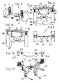
-
Figure 5 : schéma d'un système de suspension classique de l'art antérieur, -
Figure 6 : vue de face schématique d'un dispositif selon l'invention appliquée sur un train arrière d'un véhicule selon l'invention, lors d'un déplacement rectiligne, -
Figure 7 : vue de dessus schématique du dispositif de lafigure 6 , -
Figure 8 : vue de face du dispositif de lafigure 6 , lors d'un virage, -
Figure 9 : vue générale d'un train arrière complet selon l'invention et selon le principe de lafigure 6 , -
Figure 10 : vue générale d'une barre transversale de châssis intégrée au train arrière selon lafigure 9 , -
Figure 11 : vue générale d'une suspension pour train arrière selon lafigure 9 , -
Figure 12 : vue générale du train arrière de lafigure 9 selon un angle de vue opposé, -
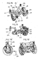
Figure 13 : vue de face d'une première variante de réalisation d'un train avant d'un véhicule selon l'invention, -
Figure 14 : vue de dessus du train avant de lafigure 13 , -
Figure 15 : vue générale du train avant desfigures 13 ,et 14 -
Figure 16 : vue générale d'une deuxième variante de réalisation d'un train avant d'un véhicule selon l'invention, -
Figure 17 : vue partielle du train avant de lafigure 16 , -
Figures 18 et 19 : vues montrant le train arrière de lafigure 9 lorsque le véhicule circule à vide, -
Figures 20 et 21 : vues montrant le train arrière de lafigure 9 lorsque le véhicule circule en pleine charge, -
Figures 22 et 23 : vues montrant le train arrière de lafigure 9 lorsque le véhicule encaisse un choc en roulant sur un obstacle, -
Figures 24 et 25 : vues montrant le train arrière de lafigure 9 en position de détente maximale.
-
Figure 5 : diagram of a conventional suspension system of the prior art, -
Figure 6 schematic front view of a device according to the invention applied to a rear axle of a vehicle according to the invention, during a rectilinear movement, -
Figure 7 : schematic top view of the device of thefigure 6 , -
Figure 8 : front view of the device of thefigure 6 during a turn, -
Figure 9 : general view of a complete rear axle according to the invention and according to the principle of thefigure 6 , -
Figure 10 : general view of a chassis crossbar integrated into the rear axle according to thefigure 9 , -
Figure 11 : general view of a rear suspension according to thefigure 9 , -
Figure 12 : general view of the rear train of thefigure 9 according to an opposite angle of view, -
Figure 13 : front view of a first embodiment of a front train of a vehicle according to the invention, -
Figure 14 : top view of the front axle of thefigure 13 , -
Figure 15 : general view of the nose gearFigures 13 and 14 , -
Figure 16 : general view of a second variant embodiment of a front train of a vehicle according to the invention, -
Figure 17 : partial view of the front train of thefigure 16 , -
Figures 18 and 19 : views showing the rear train of thefigure 9 when the vehicle is running empty, -
Figures 20 and 21 : views showing the rear train of thefigure 9 when the vehicle is traveling at full load, -
Figures 22 and 23 : views showing the rear train of thefigure 9 when the vehicle receives a shock while driving on an obstacle, -
Figures 24 and 25 : views showing the rear train of thefigure 9 in maximum relaxation position.
On se rapporte d'abord à la
Il est composé principalement de deux ressorts (c') montés entre un essieu (a') portant les roues (b') et un châssis non représenté, et d'un système de triangulation (d') de suspension monté par un système à rotule (e') sur l'essieu (a').It consists mainly of two springs (c ') mounted between an axle (a') carrying the wheels (b ') and a frame not shown, and a suspension system of triangulation (d') mounted by a system to ball joint (e ') on the axle (a').
Le point de pivot du roulis se situe sur le plan médian du châssis.The pivot point of the roll is on the median plane of the chassis.
La cote de bras de levier (x) et la raideur du ressort (c') déterminent l'angle de roulis maximal à charges équivalentes.The lever arm dimension (x) and the spring stiffness (c ') determine the maximum roll angle at equivalent loads.
Le but recherché par la demanderesse est de réaliser un train avec un système de suspension à ressorts, qui permette de réduire la largeur du véhicule, tout en répondant à toutes les contraintes indiquées précédemment.The purpose sought by the applicant is to achieve a train with a spring suspension system, which reduces the width of the vehicle, while meeting all the constraints indicated above.
Ce but est atteint de manière différente pour le train avant et pour le train arrière en raison des contraintes de présence d'une cabine de conduite et d'un tuyau d'aspiration à proximité du train avant.This goal is achieved differently for the front and rear axle because of the constraints of presence of a driver's cab and a suction pipe near the front axle.
On se rapporte à présent aux
Un train arrière selon l'invention comporte un système de suspension (201) à ressorts, en liaison avec d'une part une barre transversale ou traverse (202) de châssis et d'autre part avec un essieu (203) de roues (204).A rear axle according to the invention comprises a suspension system (201) with springs, in connection with a transverse bar or a chassis cross member (202) and secondly with an axle (203) of wheels (204). ).
La liaison entre la traverse de châssis (202) et l'essieu (203) est réalisée par deux armatures de déport (205) fixes, dont une extrémité (206) est montée fixe sur l'essieu (203) et entre les deux roues, et dont l'autre extrémité (207) est placée au-dessus d'une roue et porte une extrémité de la traverse de châssis par l'intermédiaire d'un ressort (208) travaillant en compression.The link between the chassis cross member (202) and the axle (203) is formed by two fixed offset frames (205), one end (206) of which is fixedly mounted on the axle (203) and between the two wheels. , and whose other end (207) is placed above a wheel and carries one end of the frame cross member through a spring (208) working in compression.
Les deux armatures de déport (205) sont placées symétriquement par rapport au plan médian (P) du châssis du véhicule, et leur forme et leurs dimensions permettent de surélever les ressorts et de les placer à l'aplomb des roues, tout en permettant de réduire l'écartement des roues par rapport à une conception standard et tout en maintenant la cote (x) à la valeur choisie par le calcul du roulis. (Voir
Préférentiellement, le dispositif à ressort est complété par deux butées en caoutchouc (210) montées à l'intérieur de chacun des ressorts pour limiter le déplacement vertical de la traverse (202) en cas de choc, tout en jouant un rôle dans l'amortissement.Preferably, the spring device is completed by two rubber stops (210) mounted inside each of the springs to limit the vertical displacement of the cross member (202) in the event of impact, while playing a role in damping. .
Ainsi, lors d'un choc ou d'une prise de roulis en virage (consécutif à la force centrifuge), l'effort appliqué au ressort de suspension est proportionnel à la cote (x) et en détermine la flèche (
L'entraxe important des amortisseurs détermine également la rapidité à laquelle les mouvements de balancier de la caisse seront contenus.The important spacing of the shock absorbers also determines the speed with which the pendulum movements of the body will be contained.
Préférentiellement, le train arrière selon l'invention comporte encore un dispositif amortisseur composé de deux vérins amortisseurs (211), chacun monté verticalement, entre d'une part des paliers (226) de la traverse de châssis (202) et d'autre part une des armatures de déport (205), sur l'exemple de la
L'écartement des deux vérins peut également être maintenu par une barre horizontale (209) comme sur la
Dans l'invention, la cote (x) étant identique au demi-écartement des roues au lieu de lui être nettement inférieure comme dans la conception standard, ladite cote exige moins de raideur et une capacité d'amortissement plus faible, à poids de véhicule équivalent, ce qui permet de réduire les dimensions des ressorts et des amortisseurs.In the invention, the dimension (x) being identical to the half-spacing of the wheels instead of being significantly lower as in the standard design, said dimension requires less stiffness and a lower damping capacity, vehicle weight equivalent, which reduces the dimensions of springs and dampers.
L'entraxe des ressorts (2x) est calqué sur la voie du véhicule (c'est-à-dire que la valeur 2x est supérieure à l'écartement des roues) voire sensiblement égal à l'entraxe z desdites roues, permettant de réduire l'effort sur les ressorts, de même l'entraxe important des amortisseurs permet de stabiliser et d'amortir plus rapidement la caisse.The spacing of the springs (2x) is modeled on the vehicle track (that is to say that the value 2x is greater than the spacing of the wheels) or substantially equal to the z-spacing of said wheels, to reduce the effort on the springs, like the important spacing of the dampers makes it possible to stabilize and to damp more quickly the box.
Le train arrière selon l'invention est en outre suspendu par un ensemble de suspension (212) formé d'une part de deux bielles inférieures de guidage (213) montées sous l'essieu (203) par des systèmes à pivots (215) et pouvant pivoter dans un plan parallèle au châssis et d'autre part d'un triangle supérieur (214), formé de deux bielles en V (214), et monté par un système à pivot (216) sous la barre horizontale (209) du système de suspension.The rear axle according to the invention is furthermore suspended by a suspension assembly (212) formed on the one hand by two lower guide rods (213) mounted under the axle (203) by pivots (215) and pivotable in a plane parallel to the frame and on the other hand an upper triangle (214), formed of two V-links (214), and mounted by a pivot system (216) under the horizontal bar (209) of the suspension system.
Les bielles inférieures (213) encaissent l'effort longitudinal du véhicule lié à l'amortissement, et permettent le mouvement vertical de l'essieu par les pivots (215).The lower connecting rods (213) absorb the longitudinal force of the vehicle related to the damping, and allow the vertical movement of the axle by the pivots (215).
Le triangle supérieur (214) permet d'encaisser les efforts latéraux du véhicule et permet aussi d'encaisser les déplacements verticaux de l'essieu par le pivot (216).The upper triangle (214) makes it possible to cash the lateral forces of the vehicle and also makes it possible to cash the vertical displacements of the axle by the pivot (216).
On se rapporte à présent aux
Pour un train avant, il faut tenir compte d'une contrainte supplémentaire à savoir la position et l'encombrement d'un conduit d'aspiration (de l'ordre de 250 mm de diamètre) en position centrale juste au-dessus de l'essieu avant et d'une cabine de conduite très proche longitudinalement des roues.For a front axle, an additional constraint must be taken into account, namely the position and size of a suction duct (approximately 250 mm in diameter) in a central position just above the front axle and a cab very close longitudinally of the wheels.
Il faut donc libérer une zone (217) spécifique, repérée approximativement par des pointillés, dans la partie supérieure du système de suspension (201) et la demanderesse propose deux variantes de réalisation pour répondre à cette contrainte supplémentaire.It is therefore necessary to release a specific area (217), indicated approximately by dots, in the upper part of the suspension system (201) and the applicant proposes two alternative embodiments to meet this additional constraint.
Selon une première variante des
La traverse supérieure (202) et les structures de déport (205) de la liaison entre le châssis et l'essieu sont remplacées par une structure en "U" évasée vers le haut (227), reprenant la base des ressorts (208) et permettant de dégager une zone (217) entre les vérins (211) pour le passage du tuyau et de la base d'inspiration fixe du véhicule.The upper cross member (202) and the offset structures (205) of the link between the chassis and the axle are replaced by an upwardly flared "U" structure (227), taking up the base of the springs (208) and to clear a zone (217) between the jacks (211) for the passage of the pipe and the fixed inspiration base of the vehicle.
L'ensemble de suspension (212) n'est pas modifié car le triangle supérieur (214) ne gêne pas le passage des roues.The suspension assembly (212) is not modified because the upper triangle (214) does not interfere with the passage of the wheels.
La cabine de conduite non-représentée est positionnée au-dessus des roues.The driver's cab not shown is positioned above the wheels.
Selon une deuxième variante des
Une structure pivotante (218) montée sur le pivot central (219) de l'essieu comporte deux bras (218a et 218b) disposés parallèlement au plan de roulement d'une roue et à l'intérieur de celle-ci. Chacun des bras ayant ses extrémités recourbées à 90° et portant chacune un ressort, de telle sorte que chaque paire de ressorts (220 et 221) puisse pivoter dans un plan horizontal, autour d'une roue pendant chaque opération de braquage. Chaque ressort (220 et 221) est monté en compression entre un plateau (222, 223) solidaire d'une extrémité d'un bras (218a, 218b) et la sous-face du châssis non-représentée du véhicule, et peut être équipée comme précédemment d'une butée (210) intérieure en caoutchouc.A pivoting structure (218) mounted on the central pivot (219) of the axle comprises two arms (218a and 218b) arranged parallel to the rolling plane of a wheel and inside thereof. Each of the arms having its ends curved at 90 ° and each carrying a spring, so that each pair of springs (220 and 221) can pivot in a horizontal plane around a wheel during each steering operation. Each spring (220 and 221) is mounted in compression between a plate (222, 223) integral with one end of an arm (218a, 218b) and the underside of the unrepresented chassis of the vehicle, and can be equipped as before of a stop (210) inner rubber.
Cette disposition des ressorts permet d'obtenir un entraxe des ressorts important sans occuper l'espace au-dessus de la roue et permet d'abaisser la cabine et ainsi de réduire la hauteur de la caisse du véhicule.This disposition of the springs makes it possible to obtain a large spring center distance without occupying the space above the wheel and makes it possible to lower the cabin and thus to reduce the height of the vehicle body.
En outre, les vérins amortisseurs (211) sont déportés pour permettre le braquage des roues, ils sont prévus entre la sous-face du châssis et une patte (224 ou 225) fixée sous un des plateaux (222 ou 223) de chaque structure pivotante (218).In addition, the damping cylinders (211) are deported to allow steering wheels, they are provided between the underside of the frame and a lug (224 or 225) fixed under one of the plates (222 or 223) of each pivoting structure (218).
L'ensemble de suspension (212) n'est pas modifié.The suspension assembly (212) is not modified.
Les
En
En
Les
Un véhicule dont les essieux sont équipés d'un dispositif de blocage d'essieux objet de la présente demande et qui sont en outre équipés des systèmes de suspensions décrits peut avoir une largeur inférieure à 1,60 m une cabine de conduite accueillant un conducteur, une benne arrière aussi haute que la cabine afin de conserver une bonne capacité de ramassage, une bonne stabilité même à grande vitesse, et peut rouler en toute sécurité aussi bien à faible vitesse de travail, qu'à vitesse plus élevée sur route.A vehicle whose axles are equipped with an axle locking device which is the subject of the present application and which are furthermore equipped with the suspension systems described may have a width of less than 1.60 m a driving cabin accommodating a driver, a rear body as high as the cab to maintain good pickup capability, good stability even at high speed, and can drive safely both at low work speeds and at higher speeds on the road.
Bien entendu ces équipements peuvent également, et à l'inverse, être prévus sur des véhicules plus larges dont on souhaite augmenter la surface de balayage et/ou la stabilité et éventuellement en diminuer la hauteur de cuve à volume égal.Of course, these equipment can also, and conversely, be provided on larger vehicles whose swept surface area and / or stability is desired and, if desired, to reduce the height of the tank to an equal volume.
Claims (14)
Applications Claiming Priority (4)
| Application Number | Priority Date | Filing Date | Title |
|---|---|---|---|
| FR0509875A FR2891198B1 (en) | 2005-09-28 | 2005-09-28 | SPRING LINK SYSTEM FOR NARROW VEHICLE |
| FR0511587A FR2893297B1 (en) | 2005-11-16 | 2005-11-16 | REAR AXLE LOCKING DEVICE FOR A FOUR-WHEEL ROAD CLEANING VEHICLE. |
| FR0511875A FR2893639B1 (en) | 2005-11-24 | 2005-11-24 | BRUSH HOLDER DEVICE FOR A "PUSHED" BRIDGE-TYPE ROAD CLEANING VEHICLE WHICH MAY INTEGRATE A "TIRE" BROOM FUNCTION |
| EP06366004A EP1769950B1 (en) | 2005-09-28 | 2006-09-13 | Brush holding device and cleaning vehicle with such a device |
Related Parent Applications (2)
| Application Number | Title | Priority Date | Filing Date |
|---|---|---|---|
| EP06366004.7 Division | 2006-09-13 | ||
| EP06366004A Division EP1769950B1 (en) | 2005-09-28 | 2006-09-13 | Brush holding device and cleaning vehicle with such a device |
Publications (3)
| Publication Number | Publication Date |
|---|---|
| EP2098387A2 true EP2098387A2 (en) | 2009-09-09 |
| EP2098387A3 EP2098387A3 (en) | 2009-11-18 |
| EP2098387B1 EP2098387B1 (en) | 2012-04-18 |
Family
ID=37546928
Family Applications (2)
| Application Number | Title | Priority Date | Filing Date |
|---|---|---|---|
| EP09007334A Active EP2098387B1 (en) | 2005-09-28 | 2006-09-13 | Cleaning vehicle |
| EP06366004A Active EP1769950B1 (en) | 2005-09-28 | 2006-09-13 | Brush holding device and cleaning vehicle with such a device |
Family Applications After (1)
| Application Number | Title | Priority Date | Filing Date |
|---|---|---|---|
| EP06366004A Active EP1769950B1 (en) | 2005-09-28 | 2006-09-13 | Brush holding device and cleaning vehicle with such a device |
Country Status (3)
| Country | Link |
|---|---|
| EP (2) | EP2098387B1 (en) |
| AT (1) | ATE449215T1 (en) |
| DE (1) | DE602006010498D1 (en) |
Families Citing this family (13)
| Publication number | Priority date | Publication date | Assignee | Title |
|---|---|---|---|---|
| US7938415B2 (en) | 2008-03-10 | 2011-05-10 | Deere & Company | Suspended axle for sprayer |
| WO2012171579A1 (en) | 2011-06-17 | 2012-12-20 | Alfred Kärcher Gmbh & Co. Kg | Sweeping vehicle having a brush disk adjuster |
| EP2721219B1 (en) * | 2011-06-17 | 2015-03-11 | Alfred Kärcher GmbH & Co. KG | Sweeping vehicle |
| CN106192833B (en) * | 2016-08-30 | 2018-06-29 | 珠海亿华电动车辆有限公司 | A kind of sweep device and electric ground sweeper |
| CN107969206A (en) * | 2017-12-24 | 2018-05-01 | 广西广付金商贸有限公司 | A kind of new sweet potato harvester cleaning device |
| CN108487152B (en) * | 2018-04-03 | 2020-04-14 | 益阳瀚鑫机械制造有限公司 | Environment-friendly road cleaning vehicle with adjustable cleaning range |
| CN108560464A (en) * | 2018-05-18 | 2018-09-21 | 邢台职业技术学院 | A kind of Environmental sanitation cleaning vehicle |
| CN108612015B (en) * | 2018-05-24 | 2024-07-02 | 扬州金威环保科技有限公司 | Modular wet sweeping and washing device capable of being exchanged rapidly |
| CN109235338A (en) * | 2018-10-12 | 2019-01-18 | 扬州三源机械有限公司 | Sweep disc mechanism in the comprehensive no dead angle of one kind |
| CN111942262B (en) * | 2020-09-21 | 2024-04-23 | 洛阳安驰汽车制造有限公司 | Precision equipment carries car |
| CN112663546B (en) * | 2020-12-23 | 2022-03-18 | 提尔环保科技江苏有限公司 | Driving type sweeper |
| CN112681207B (en) * | 2020-12-24 | 2022-06-28 | 北京泛华新兴体育产业股份有限公司 | Ice and snow clearing device and snow sweeper using same |
| CN113679308B (en) * | 2021-10-13 | 2024-08-23 | 安徽橙犀科技有限公司 | Automatic locking type parallel movement water absorption and lifting mechanism |
Citations (9)
| Publication number | Priority date | Publication date | Assignee | Title |
|---|---|---|---|---|
| US2139185A (en) * | 1936-08-12 | 1938-12-06 | Teves Kg Alfred | Pressure actuated piston lock release |
| SU492403A1 (en) * | 1973-11-26 | 1975-11-25 | Головное Союзное Конструкторское Бюро По Автобусам Министерства Автомобильной Промышленности Ссср | Independent vehicle wheel suspension |
| US4770264A (en) * | 1985-12-02 | 1988-09-13 | Group Lotus Plc | Vehicle steering system |
| EP0375409A2 (en) * | 1988-12-23 | 1990-06-27 | Dlma Transportation Inc. | Rear wheel suspension and steering system |
| WO1997026170A1 (en) * | 1996-01-17 | 1997-07-24 | Carlton John Davis | Control system for a steerable axle and a steerable axle |
| US6086074A (en) * | 1995-11-15 | 2000-07-11 | Oshkosh Truck Corporation | Steering lock system |
| EP1136343A2 (en) * | 2000-03-21 | 2001-09-26 | Carlton John Davis | Control apparatus and method for a steerable axle |
| FR2808733A1 (en) * | 2000-05-09 | 2001-11-16 | Mathieu Yno S A | Axle system, for road maintenance vehicles, is made of a central support section, which can be fitted with double or single interface modules |
| EP1243497A1 (en) * | 2001-03-20 | 2002-09-25 | FAUN GmbH | Motor vehicle with at least one rear axle with steerable rear wheels |
Family Cites Families (3)
| Publication number | Priority date | Publication date | Assignee | Title |
|---|---|---|---|---|
| US754521A (en) | 1903-06-05 | 1904-03-15 | Eli C Vale | Separable link. |
| IT1195887B (en) * | 1986-07-31 | 1988-10-27 | Dulevo Spa | ROAD SWEEPER MACHINE FOR WASTE COLLECTION |
| DE10106471A1 (en) * | 2001-02-13 | 2002-08-14 | Kuepper Weisser Gmbh | Sweeping machine with rotary plate brush reciprocated via linear guide device relative to suction opening |
-
2006
- 2006-09-13 EP EP09007334A patent/EP2098387B1/en active Active
- 2006-09-13 AT AT06366004T patent/ATE449215T1/en not_active IP Right Cessation
- 2006-09-13 EP EP06366004A patent/EP1769950B1/en active Active
- 2006-09-13 DE DE602006010498T patent/DE602006010498D1/en active Active
Patent Citations (9)
| Publication number | Priority date | Publication date | Assignee | Title |
|---|---|---|---|---|
| US2139185A (en) * | 1936-08-12 | 1938-12-06 | Teves Kg Alfred | Pressure actuated piston lock release |
| SU492403A1 (en) * | 1973-11-26 | 1975-11-25 | Головное Союзное Конструкторское Бюро По Автобусам Министерства Автомобильной Промышленности Ссср | Independent vehicle wheel suspension |
| US4770264A (en) * | 1985-12-02 | 1988-09-13 | Group Lotus Plc | Vehicle steering system |
| EP0375409A2 (en) * | 1988-12-23 | 1990-06-27 | Dlma Transportation Inc. | Rear wheel suspension and steering system |
| US6086074A (en) * | 1995-11-15 | 2000-07-11 | Oshkosh Truck Corporation | Steering lock system |
| WO1997026170A1 (en) * | 1996-01-17 | 1997-07-24 | Carlton John Davis | Control system for a steerable axle and a steerable axle |
| EP1136343A2 (en) * | 2000-03-21 | 2001-09-26 | Carlton John Davis | Control apparatus and method for a steerable axle |
| FR2808733A1 (en) * | 2000-05-09 | 2001-11-16 | Mathieu Yno S A | Axle system, for road maintenance vehicles, is made of a central support section, which can be fitted with double or single interface modules |
| EP1243497A1 (en) * | 2001-03-20 | 2002-09-25 | FAUN GmbH | Motor vehicle with at least one rear axle with steerable rear wheels |
Also Published As
| Publication number | Publication date |
|---|---|
| DE602006010498D1 (en) | 2009-12-31 |
| ATE449215T1 (en) | 2009-12-15 |
| EP2098387B1 (en) | 2012-04-18 |
| EP1769950B1 (en) | 2009-11-18 |
| EP1769950A2 (en) | 2007-04-04 |
| EP2098387A3 (en) | 2009-11-18 |
| EP1769950A3 (en) | 2008-05-07 |
Similar Documents
| Publication | Publication Date | Title |
|---|---|---|
| EP2098387B1 (en) | Cleaning vehicle | |
| EP2782814B1 (en) | Compact urban vehicle | |
| EP3691959B1 (en) | Couplable automotive road vehicle with compact steering and suspension | |
| FR2630683A1 (en) | VEHICLE FOR MOVING VEHICLES ON RAILS | |
| EP3222485B1 (en) | Railway vehicle bogie comprising an offset primary suspension device | |
| FR2694240A1 (en) | Adjustable suspension for motor vehicle - has dead rear axle, and parallel link rear suspension, with ride height control and adjustable lower links | |
| WO2006067087A1 (en) | Suspended axle for a vehicle | |
| EP4041574B1 (en) | Hitchable automobile road vehicle and automobile road convoy formed by vehicles with improved roadholding | |
| WO2017168065A1 (en) | Hydraulic suspension system for a vehicle | |
| EP3222486B1 (en) | Railway vehicle bogie comprising a lowered body | |
| EP2822833B1 (en) | Pendulation device absorbing transverse and longitudinal forces | |
| EP0750072B1 (en) | High performance compact automotive urban sweeper with inverse mounted turbine | |
| LU86674A1 (en) | BIVALENT VEHICLE FOR ROAD AND RAIL WALKING | |
| EP3744615B1 (en) | Hitchable road vehicle comprising devices for front and rear linkage | |
| FR2902698A1 (en) | Suspended rear axle for e.g. passenger car, has crossbeam including ends that are connected to respective longitudinal arms for forming rigid parts, and chuck stop limiting wheel`s steering movement towards interior of vehicle | |
| FR2911571A1 (en) | DEVICE FOR PASSING A FOUR-WHEEL MODE FOR A MOTOR VEHICLE FOR CLEANING ROADS | |
| FR2891198A1 (en) | Street cleaning vehicle has chassis mounted on pair of vertical springs attached to upper ends of curved arms whose lower ends are attached to vehicle axle | |
| FR2977559A1 (en) | Two-wheeled vehicle e.g. motor cycle, has seat backrest including structural reinforcement whose upper part is fixed at rigid roof element to form reinforcement arch for enabling passenger compartment to withstand vertical compressive loads | |
| FR3049252A1 (en) | BOGIE COMPRISING A RIGID CONNECTION BETWEEN THE AXLE BOXES AND THE RAIL VEHICLE ASSOCIATED THEREWITH | |
| EP3042821B1 (en) | Bogie with centralized primary suspension | |
| FR2491005A1 (en) | Tractor for road or rail use - has road wheel on rail allowing eccentric loading of jib arm | |
| FR3049504B1 (en) | HYDRAULIC SUSPENSION SYSTEM OF A VEHICLE | |
| FR2926492A1 (en) | Running gear e.g. front gear, sub assembly for motor vehicle, has device for adjusting height of steering stub axle with respect to suspension system for adjusting ground clearance of vehicle independently of displacement of system | |
| WO2022023378A1 (en) | Running gear for an amphibious vehicle | |
| EP1954511B1 (en) | Light rail motor tractor for railway transport for guiding and structurally distinct traction operations |
Legal Events
| Date | Code | Title | Description |
|---|---|---|---|
| PUAI | Public reference made under article 153(3) epc to a published international application that has entered the european phase |
Free format text: ORIGINAL CODE: 0009012 |
|
| AC | Divisional application: reference to earlier application |
Ref document number: 1769950 Country of ref document: EP Kind code of ref document: P |
|
| AK | Designated contracting states |
Kind code of ref document: A2 Designated state(s): AT BE BG CH CY CZ DE DK EE ES FI FR GB GR HU IE IS IT LI LT LU LV MC NL PL PT RO SE SI SK TR |
|
| PUAL | Search report despatched |
Free format text: ORIGINAL CODE: 0009013 |
|
| AK | Designated contracting states |
Kind code of ref document: A3 Designated state(s): AT BE BG CH CY CZ DE DK EE ES FI FR GB GR HU IE IS IT LI LT LU LV MC NL PL PT RO SE SI SK TR |
|
| RIC1 | Information provided on ipc code assigned before grant |
Ipc: B60G 9/04 20060101ALI20091013BHEP Ipc: E01H 1/00 20060101ALI20091013BHEP Ipc: B62D 9/00 20060101ALI20091013BHEP Ipc: B62D 7/15 20060101AFI20091013BHEP |
|
| RIN1 | Information on inventor provided before grant (corrected) |
Inventor name: ROUXEL, ANTOINE Inventor name: DESREUMAUX, YANN |
|
| 17P | Request for examination filed |
Effective date: 20100518 |
|
| 17Q | First examination report despatched |
Effective date: 20100826 |
|
| GRAP | Despatch of communication of intention to grant a patent |
Free format text: ORIGINAL CODE: EPIDOSNIGR1 |
|
| GRAS | Grant fee paid |
Free format text: ORIGINAL CODE: EPIDOSNIGR3 |
|
| GRAA | (expected) grant |
Free format text: ORIGINAL CODE: 0009210 |
|
| AC | Divisional application: reference to earlier application |
Ref document number: 1769950 Country of ref document: EP Kind code of ref document: P |
|
| AK | Designated contracting states |
Kind code of ref document: B1 Designated state(s): AT BE BG CH CY CZ DE DK EE ES FI FR GB GR HU IE IS IT LI LT LU LV MC NL PL PT RO SE SI SK TR |
|
| REG | Reference to a national code |
Ref country code: GB Ref legal event code: FG4D Free format text: NOT ENGLISH |
|
| REG | Reference to a national code |
Ref country code: CH Ref legal event code: EP |
|
| REG | Reference to a national code |
Ref country code: IE Ref legal event code: FG4D Free format text: LANGUAGE OF EP DOCUMENT: FRENCH |
|
| REG | Reference to a national code |
Ref country code: AT Ref legal event code: REF Ref document number: 553981 Country of ref document: AT Kind code of ref document: T Effective date: 20120515 |
|
| REG | Reference to a national code |
Ref country code: DE Ref legal event code: R096 Ref document number: 602006029007 Country of ref document: DE Effective date: 20120614 |
|
| REG | Reference to a national code |
Ref country code: CH Ref legal event code: NV Representative=s name: MEYER & KOLLEGEN |
|
| REG | Reference to a national code |
Ref country code: NL Ref legal event code: VDEP Effective date: 20120418 |
|
| REG | Reference to a national code |
Ref country code: AT Ref legal event code: MK05 Ref document number: 553981 Country of ref document: AT Kind code of ref document: T Effective date: 20120418 |
|
| LTIE | Lt: invalidation of european patent or patent extension |
Effective date: 20120418 |
|
| PG25 | Lapsed in a contracting state [announced via postgrant information from national office to epo] |
Ref country code: CY Free format text: LAPSE BECAUSE OF FAILURE TO SUBMIT A TRANSLATION OF THE DESCRIPTION OR TO PAY THE FEE WITHIN THE PRESCRIBED TIME-LIMIT Effective date: 20120418 Ref country code: FI Free format text: LAPSE BECAUSE OF FAILURE TO SUBMIT A TRANSLATION OF THE DESCRIPTION OR TO PAY THE FEE WITHIN THE PRESCRIBED TIME-LIMIT Effective date: 20120418 Ref country code: IS Free format text: LAPSE BECAUSE OF FAILURE TO SUBMIT A TRANSLATION OF THE DESCRIPTION OR TO PAY THE FEE WITHIN THE PRESCRIBED TIME-LIMIT Effective date: 20120818 Ref country code: PL Free format text: LAPSE BECAUSE OF FAILURE TO SUBMIT A TRANSLATION OF THE DESCRIPTION OR TO PAY THE FEE WITHIN THE PRESCRIBED TIME-LIMIT Effective date: 20120418 Ref country code: LT Free format text: LAPSE BECAUSE OF FAILURE TO SUBMIT A TRANSLATION OF THE DESCRIPTION OR TO PAY THE FEE WITHIN THE PRESCRIBED TIME-LIMIT Effective date: 20120418 Ref country code: SE Free format text: LAPSE BECAUSE OF FAILURE TO SUBMIT A TRANSLATION OF THE DESCRIPTION OR TO PAY THE FEE WITHIN THE PRESCRIBED TIME-LIMIT Effective date: 20120418 |
|
| PG25 | Lapsed in a contracting state [announced via postgrant information from national office to epo] |
Ref country code: LV Free format text: LAPSE BECAUSE OF FAILURE TO SUBMIT A TRANSLATION OF THE DESCRIPTION OR TO PAY THE FEE WITHIN THE PRESCRIBED TIME-LIMIT Effective date: 20120418 Ref country code: PT Free format text: LAPSE BECAUSE OF FAILURE TO SUBMIT A TRANSLATION OF THE DESCRIPTION OR TO PAY THE FEE WITHIN THE PRESCRIBED TIME-LIMIT Effective date: 20120820 Ref country code: GR Free format text: LAPSE BECAUSE OF FAILURE TO SUBMIT A TRANSLATION OF THE DESCRIPTION OR TO PAY THE FEE WITHIN THE PRESCRIBED TIME-LIMIT Effective date: 20120719 Ref country code: SI Free format text: LAPSE BECAUSE OF FAILURE TO SUBMIT A TRANSLATION OF THE DESCRIPTION OR TO PAY THE FEE WITHIN THE PRESCRIBED TIME-LIMIT Effective date: 20120418 |
|
| PG25 | Lapsed in a contracting state [announced via postgrant information from national office to epo] |
Ref country code: NL Free format text: LAPSE BECAUSE OF FAILURE TO SUBMIT A TRANSLATION OF THE DESCRIPTION OR TO PAY THE FEE WITHIN THE PRESCRIBED TIME-LIMIT Effective date: 20120418 Ref country code: SK Free format text: LAPSE BECAUSE OF FAILURE TO SUBMIT A TRANSLATION OF THE DESCRIPTION OR TO PAY THE FEE WITHIN THE PRESCRIBED TIME-LIMIT Effective date: 20120418 Ref country code: RO Free format text: LAPSE BECAUSE OF FAILURE TO SUBMIT A TRANSLATION OF THE DESCRIPTION OR TO PAY THE FEE WITHIN THE PRESCRIBED TIME-LIMIT Effective date: 20120418 Ref country code: EE Free format text: LAPSE BECAUSE OF FAILURE TO SUBMIT A TRANSLATION OF THE DESCRIPTION OR TO PAY THE FEE WITHIN THE PRESCRIBED TIME-LIMIT Effective date: 20120418 Ref country code: CZ Free format text: LAPSE BECAUSE OF FAILURE TO SUBMIT A TRANSLATION OF THE DESCRIPTION OR TO PAY THE FEE WITHIN THE PRESCRIBED TIME-LIMIT Effective date: 20120418 Ref country code: AT Free format text: LAPSE BECAUSE OF FAILURE TO SUBMIT A TRANSLATION OF THE DESCRIPTION OR TO PAY THE FEE WITHIN THE PRESCRIBED TIME-LIMIT Effective date: 20120418 Ref country code: DK Free format text: LAPSE BECAUSE OF FAILURE TO SUBMIT A TRANSLATION OF THE DESCRIPTION OR TO PAY THE FEE WITHIN THE PRESCRIBED TIME-LIMIT Effective date: 20120418 |
|
| PLBE | No opposition filed within time limit |
Free format text: ORIGINAL CODE: 0009261 |
|
| STAA | Information on the status of an ep patent application or granted ep patent |
Free format text: STATUS: NO OPPOSITION FILED WITHIN TIME LIMIT |
|
| PG25 | Lapsed in a contracting state [announced via postgrant information from national office to epo] |
Ref country code: IT Free format text: LAPSE BECAUSE OF FAILURE TO SUBMIT A TRANSLATION OF THE DESCRIPTION OR TO PAY THE FEE WITHIN THE PRESCRIBED TIME-LIMIT Effective date: 20120418 |
|
| 26N | No opposition filed |
Effective date: 20130121 |
|
| BERE | Be: lapsed |
Owner name: MATHIEU Effective date: 20120930 |
|
| PG25 | Lapsed in a contracting state [announced via postgrant information from national office to epo] |
Ref country code: ES Free format text: LAPSE BECAUSE OF FAILURE TO SUBMIT A TRANSLATION OF THE DESCRIPTION OR TO PAY THE FEE WITHIN THE PRESCRIBED TIME-LIMIT Effective date: 20120729 Ref country code: MC Free format text: LAPSE BECAUSE OF NON-PAYMENT OF DUE FEES Effective date: 20120930 |
|
| REG | Reference to a national code |
Ref country code: DE Ref legal event code: R097 Ref document number: 602006029007 Country of ref document: DE Effective date: 20130121 |
|
| REG | Reference to a national code |
Ref country code: IE Ref legal event code: MM4A |
|
| PG25 | Lapsed in a contracting state [announced via postgrant information from national office to epo] |
Ref country code: BG Free format text: LAPSE BECAUSE OF FAILURE TO SUBMIT A TRANSLATION OF THE DESCRIPTION OR TO PAY THE FEE WITHIN THE PRESCRIBED TIME-LIMIT Effective date: 20120718 Ref country code: IE Free format text: LAPSE BECAUSE OF NON-PAYMENT OF DUE FEES Effective date: 20120913 Ref country code: BE Free format text: LAPSE BECAUSE OF NON-PAYMENT OF DUE FEES Effective date: 20120930 |
|
| PG25 | Lapsed in a contracting state [announced via postgrant information from national office to epo] |
Ref country code: TR Free format text: LAPSE BECAUSE OF FAILURE TO SUBMIT A TRANSLATION OF THE DESCRIPTION OR TO PAY THE FEE WITHIN THE PRESCRIBED TIME-LIMIT Effective date: 20120418 |
|
| PG25 | Lapsed in a contracting state [announced via postgrant information from national office to epo] |
Ref country code: LU Free format text: LAPSE BECAUSE OF NON-PAYMENT OF DUE FEES Effective date: 20120913 |
|
| PG25 | Lapsed in a contracting state [announced via postgrant information from national office to epo] |
Ref country code: HU Free format text: LAPSE BECAUSE OF FAILURE TO SUBMIT A TRANSLATION OF THE DESCRIPTION OR TO PAY THE FEE WITHIN THE PRESCRIBED TIME-LIMIT Effective date: 20060913 |
|
| REG | Reference to a national code |
Ref country code: FR Ref legal event code: PLFP Year of fee payment: 11 |
|
| REG | Reference to a national code |
Ref country code: FR Ref legal event code: PLFP Year of fee payment: 12 |
|
| REG | Reference to a national code |
Ref country code: FR Ref legal event code: PLFP Year of fee payment: 13 |
|
| PGFP | Annual fee paid to national office [announced via postgrant information from national office to epo] |
Ref country code: DE Payment date: 20230928 Year of fee payment: 18 |
|
| PGFP | Annual fee paid to national office [announced via postgrant information from national office to epo] |
Ref country code: CH Payment date: 20231004 Year of fee payment: 18 |
|
| P01 | Opt-out of the competence of the unified patent court (upc) registered |
Effective date: 20240122 |
|
| PGFP | Annual fee paid to national office [announced via postgrant information from national office to epo] |
Ref country code: GB Payment date: 20240925 Year of fee payment: 19 |
|
| PGFP | Annual fee paid to national office [announced via postgrant information from national office to epo] |
Ref country code: FR Payment date: 20240916 Year of fee payment: 19 |