EP2098202A1 - Saugfähiger artikel - Google Patents
Saugfähiger artikel Download PDFInfo
- Publication number
- EP2098202A1 EP2098202A1 EP06843652A EP06843652A EP2098202A1 EP 2098202 A1 EP2098202 A1 EP 2098202A1 EP 06843652 A EP06843652 A EP 06843652A EP 06843652 A EP06843652 A EP 06843652A EP 2098202 A1 EP2098202 A1 EP 2098202A1
- Authority
- EP
- European Patent Office
- Prior art keywords
- guide unit
- liquid guide
- absorbent article
- urine
- absorber
- Prior art date
- Legal status (The legal status is an assumption and is not a legal conclusion. Google has not performed a legal analysis and makes no representation as to the accuracy of the status listed.)
- Withdrawn
Links
Images


Classifications
-
- A—HUMAN NECESSITIES
- A61—MEDICAL OR VETERINARY SCIENCE; HYGIENE
- A61F—FILTERS IMPLANTABLE INTO BLOOD VESSELS; PROSTHESES; DEVICES PROVIDING PATENCY TO, OR PREVENTING COLLAPSING OF, TUBULAR STRUCTURES OF THE BODY, e.g. STENTS; ORTHOPAEDIC, NURSING OR CONTRACEPTIVE DEVICES; FOMENTATION; TREATMENT OR PROTECTION OF EYES OR EARS; BANDAGES, DRESSINGS OR ABSORBENT PADS; FIRST-AID KITS
- A61F13/00—Bandages or dressings; Absorbent pads
- A61F13/15—Absorbent pads, e.g. sanitary towels, swabs or tampons for external or internal application to the body; Supporting or fastening means therefor; Tampon applicators
- A61F13/45—Absorbent pads, e.g. sanitary towels, swabs or tampons for external or internal application to the body; Supporting or fastening means therefor; Tampon applicators characterised by the shape
- A61F13/49—Absorbent articles specially adapted to be worn around the waist, e.g. diapers
- A61F13/495—Absorbent articles specially adapted to be worn around the waist, e.g. diapers with faecal cavity
-
- A—HUMAN NECESSITIES
- A61—MEDICAL OR VETERINARY SCIENCE; HYGIENE
- A61F—FILTERS IMPLANTABLE INTO BLOOD VESSELS; PROSTHESES; DEVICES PROVIDING PATENCY TO, OR PREVENTING COLLAPSING OF, TUBULAR STRUCTURES OF THE BODY, e.g. STENTS; ORTHOPAEDIC, NURSING OR CONTRACEPTIVE DEVICES; FOMENTATION; TREATMENT OR PROTECTION OF EYES OR EARS; BANDAGES, DRESSINGS OR ABSORBENT PADS; FIRST-AID KITS
- A61F13/00—Bandages or dressings; Absorbent pads
- A61F13/15—Absorbent pads, e.g. sanitary towels, swabs or tampons for external or internal application to the body; Supporting or fastening means therefor; Tampon applicators
- A61F13/45—Absorbent pads, e.g. sanitary towels, swabs or tampons for external or internal application to the body; Supporting or fastening means therefor; Tampon applicators characterised by the shape
- A61F13/49—Absorbent articles specially adapted to be worn around the waist, e.g. diapers
- A61F13/494—Absorbent articles specially adapted to be worn around the waist, e.g. diapers characterised by edge leakage prevention means
- A61F13/49406—Absorbent articles specially adapted to be worn around the waist, e.g. diapers characterised by edge leakage prevention means the edge leakage prevention means being at the crotch region
- A61F13/4946—Absorbent articles specially adapted to be worn around the waist, e.g. diapers characterised by edge leakage prevention means the edge leakage prevention means being at the crotch region the edge leakage prevention means being an absorbent medium
-
- A—HUMAN NECESSITIES
- A61—MEDICAL OR VETERINARY SCIENCE; HYGIENE
- A61F—FILTERS IMPLANTABLE INTO BLOOD VESSELS; PROSTHESES; DEVICES PROVIDING PATENCY TO, OR PREVENTING COLLAPSING OF, TUBULAR STRUCTURES OF THE BODY, e.g. STENTS; ORTHOPAEDIC, NURSING OR CONTRACEPTIVE DEVICES; FOMENTATION; TREATMENT OR PROTECTION OF EYES OR EARS; BANDAGES, DRESSINGS OR ABSORBENT PADS; FIRST-AID KITS
- A61F13/00—Bandages or dressings; Absorbent pads
- A61F13/15—Absorbent pads, e.g. sanitary towels, swabs or tampons for external or internal application to the body; Supporting or fastening means therefor; Tampon applicators
- A61F13/45—Absorbent pads, e.g. sanitary towels, swabs or tampons for external or internal application to the body; Supporting or fastening means therefor; Tampon applicators characterised by the shape
- A61F13/49—Absorbent articles specially adapted to be worn around the waist, e.g. diapers
- A61F13/494—Absorbent articles specially adapted to be worn around the waist, e.g. diapers characterised by edge leakage prevention means
- A61F13/49473—Absorbent articles specially adapted to be worn around the waist, e.g. diapers characterised by edge leakage prevention means the edge leakage prevention means having a continuous closed form, e.g. circle, ellipse, rectangle
-
- A—HUMAN NECESSITIES
- A61—MEDICAL OR VETERINARY SCIENCE; HYGIENE
- A61F—FILTERS IMPLANTABLE INTO BLOOD VESSELS; PROSTHESES; DEVICES PROVIDING PATENCY TO, OR PREVENTING COLLAPSING OF, TUBULAR STRUCTURES OF THE BODY, e.g. STENTS; ORTHOPAEDIC, NURSING OR CONTRACEPTIVE DEVICES; FOMENTATION; TREATMENT OR PROTECTION OF EYES OR EARS; BANDAGES, DRESSINGS OR ABSORBENT PADS; FIRST-AID KITS
- A61F13/00—Bandages or dressings; Absorbent pads
- A61F13/15—Absorbent pads, e.g. sanitary towels, swabs or tampons for external or internal application to the body; Supporting or fastening means therefor; Tampon applicators
- A61F13/53—Absorbent pads, e.g. sanitary towels, swabs or tampons for external or internal application to the body; Supporting or fastening means therefor; Tampon applicators characterised by the absorbing medium
- A61F13/534—Absorbent pads, e.g. sanitary towels, swabs or tampons for external or internal application to the body; Supporting or fastening means therefor; Tampon applicators characterised by the absorbing medium having an inhomogeneous composition through the thickness of the pad
- A61F13/537—Absorbent pads, e.g. sanitary towels, swabs or tampons for external or internal application to the body; Supporting or fastening means therefor; Tampon applicators characterised by the absorbing medium having an inhomogeneous composition through the thickness of the pad characterised by a layer facilitating or inhibiting flow in one direction or plane, e.g. a wicking layer
- A61F13/53708—Absorbent pads, e.g. sanitary towels, swabs or tampons for external or internal application to the body; Supporting or fastening means therefor; Tampon applicators characterised by the absorbing medium having an inhomogeneous composition through the thickness of the pad characterised by a layer facilitating or inhibiting flow in one direction or plane, e.g. a wicking layer the layer having a promotional function on liquid propagation in at least one direction
- A61F13/53713—Absorbent pads, e.g. sanitary towels, swabs or tampons for external or internal application to the body; Supporting or fastening means therefor; Tampon applicators characterised by the absorbing medium having an inhomogeneous composition through the thickness of the pad characterised by a layer facilitating or inhibiting flow in one direction or plane, e.g. a wicking layer the layer having a promotional function on liquid propagation in at least one direction the layer having a promotional function on liquid propagation in the vertical direction
-
- A—HUMAN NECESSITIES
- A61—MEDICAL OR VETERINARY SCIENCE; HYGIENE
- A61F—FILTERS IMPLANTABLE INTO BLOOD VESSELS; PROSTHESES; DEVICES PROVIDING PATENCY TO, OR PREVENTING COLLAPSING OF, TUBULAR STRUCTURES OF THE BODY, e.g. STENTS; ORTHOPAEDIC, NURSING OR CONTRACEPTIVE DEVICES; FOMENTATION; TREATMENT OR PROTECTION OF EYES OR EARS; BANDAGES, DRESSINGS OR ABSORBENT PADS; FIRST-AID KITS
- A61F13/00—Bandages or dressings; Absorbent pads
- A61F13/15—Absorbent pads, e.g. sanitary towels, swabs or tampons for external or internal application to the body; Supporting or fastening means therefor; Tampon applicators
- A61F13/53—Absorbent pads, e.g. sanitary towels, swabs or tampons for external or internal application to the body; Supporting or fastening means therefor; Tampon applicators characterised by the absorbing medium
- A61F13/534—Absorbent pads, e.g. sanitary towels, swabs or tampons for external or internal application to the body; Supporting or fastening means therefor; Tampon applicators characterised by the absorbing medium having an inhomogeneous composition through the thickness of the pad
- A61F13/537—Absorbent pads, e.g. sanitary towels, swabs or tampons for external or internal application to the body; Supporting or fastening means therefor; Tampon applicators characterised by the absorbing medium having an inhomogeneous composition through the thickness of the pad characterised by a layer facilitating or inhibiting flow in one direction or plane, e.g. a wicking layer
- A61F13/53708—Absorbent pads, e.g. sanitary towels, swabs or tampons for external or internal application to the body; Supporting or fastening means therefor; Tampon applicators characterised by the absorbing medium having an inhomogeneous composition through the thickness of the pad characterised by a layer facilitating or inhibiting flow in one direction or plane, e.g. a wicking layer the layer having a promotional function on liquid propagation in at least one direction
- A61F13/53717—Absorbent pads, e.g. sanitary towels, swabs or tampons for external or internal application to the body; Supporting or fastening means therefor; Tampon applicators characterised by the absorbing medium having an inhomogeneous composition through the thickness of the pad characterised by a layer facilitating or inhibiting flow in one direction or plane, e.g. a wicking layer the layer having a promotional function on liquid propagation in at least one direction the layer having a promotional function on liquid propagation in the horizontal direction
-
- A—HUMAN NECESSITIES
- A61—MEDICAL OR VETERINARY SCIENCE; HYGIENE
- A61F—FILTERS IMPLANTABLE INTO BLOOD VESSELS; PROSTHESES; DEVICES PROVIDING PATENCY TO, OR PREVENTING COLLAPSING OF, TUBULAR STRUCTURES OF THE BODY, e.g. STENTS; ORTHOPAEDIC, NURSING OR CONTRACEPTIVE DEVICES; FOMENTATION; TREATMENT OR PROTECTION OF EYES OR EARS; BANDAGES, DRESSINGS OR ABSORBENT PADS; FIRST-AID KITS
- A61F13/00—Bandages or dressings; Absorbent pads
- A61F13/15—Absorbent pads, e.g. sanitary towels, swabs or tampons for external or internal application to the body; Supporting or fastening means therefor; Tampon applicators
- A61F13/51—Absorbent pads, e.g. sanitary towels, swabs or tampons for external or internal application to the body; Supporting or fastening means therefor; Tampon applicators characterised by the outer layers
- A61F13/511—Topsheet, i.e. the permeable cover or layer facing the skin
- A61F13/513—Topsheet, i.e. the permeable cover or layer facing the skin characterised by its function or properties, e.g. stretchability, breathability, rewet, visual effect; having areas of different permeability
- A61F2013/51383—Topsheet, i.e. the permeable cover or layer facing the skin characterised by its function or properties, e.g. stretchability, breathability, rewet, visual effect; having areas of different permeability being adapted for female properties
-
- A—HUMAN NECESSITIES
- A61—MEDICAL OR VETERINARY SCIENCE; HYGIENE
- A61F—FILTERS IMPLANTABLE INTO BLOOD VESSELS; PROSTHESES; DEVICES PROVIDING PATENCY TO, OR PREVENTING COLLAPSING OF, TUBULAR STRUCTURES OF THE BODY, e.g. STENTS; ORTHOPAEDIC, NURSING OR CONTRACEPTIVE DEVICES; FOMENTATION; TREATMENT OR PROTECTION OF EYES OR EARS; BANDAGES, DRESSINGS OR ABSORBENT PADS; FIRST-AID KITS
- A61F13/00—Bandages or dressings; Absorbent pads
- A61F13/15—Absorbent pads, e.g. sanitary towels, swabs or tampons for external or internal application to the body; Supporting or fastening means therefor; Tampon applicators
- A61F13/51—Absorbent pads, e.g. sanitary towels, swabs or tampons for external or internal application to the body; Supporting or fastening means therefor; Tampon applicators characterised by the outer layers
- A61F13/511—Topsheet, i.e. the permeable cover or layer facing the skin
- A61F13/513—Topsheet, i.e. the permeable cover or layer facing the skin characterised by its function or properties, e.g. stretchability, breathability, rewet, visual effect; having areas of different permeability
- A61F2013/51388—Topsheet, i.e. the permeable cover or layer facing the skin characterised by its function or properties, e.g. stretchability, breathability, rewet, visual effect; having areas of different permeability being adapted to male properties
-
- A—HUMAN NECESSITIES
- A61—MEDICAL OR VETERINARY SCIENCE; HYGIENE
- A61F—FILTERS IMPLANTABLE INTO BLOOD VESSELS; PROSTHESES; DEVICES PROVIDING PATENCY TO, OR PREVENTING COLLAPSING OF, TUBULAR STRUCTURES OF THE BODY, e.g. STENTS; ORTHOPAEDIC, NURSING OR CONTRACEPTIVE DEVICES; FOMENTATION; TREATMENT OR PROTECTION OF EYES OR EARS; BANDAGES, DRESSINGS OR ABSORBENT PADS; FIRST-AID KITS
- A61F13/00—Bandages or dressings; Absorbent pads
- A61F13/15—Absorbent pads, e.g. sanitary towels, swabs or tampons for external or internal application to the body; Supporting or fastening means therefor; Tampon applicators
- A61F13/53—Absorbent pads, e.g. sanitary towels, swabs or tampons for external or internal application to the body; Supporting or fastening means therefor; Tampon applicators characterised by the absorbing medium
- A61F2013/530481—Absorbent pads, e.g. sanitary towels, swabs or tampons for external or internal application to the body; Supporting or fastening means therefor; Tampon applicators characterised by the absorbing medium having superabsorbent materials, i.e. highly absorbent polymer gel materials
- A61F2013/5307—Absorbent pads, e.g. sanitary towels, swabs or tampons for external or internal application to the body; Supporting or fastening means therefor; Tampon applicators characterised by the absorbing medium having superabsorbent materials, i.e. highly absorbent polymer gel materials characterized by the quantity or ratio of superabsorbent material
-
- A—HUMAN NECESSITIES
- A61—MEDICAL OR VETERINARY SCIENCE; HYGIENE
- A61F—FILTERS IMPLANTABLE INTO BLOOD VESSELS; PROSTHESES; DEVICES PROVIDING PATENCY TO, OR PREVENTING COLLAPSING OF, TUBULAR STRUCTURES OF THE BODY, e.g. STENTS; ORTHOPAEDIC, NURSING OR CONTRACEPTIVE DEVICES; FOMENTATION; TREATMENT OR PROTECTION OF EYES OR EARS; BANDAGES, DRESSINGS OR ABSORBENT PADS; FIRST-AID KITS
- A61F13/00—Bandages or dressings; Absorbent pads
- A61F13/15—Absorbent pads, e.g. sanitary towels, swabs or tampons for external or internal application to the body; Supporting or fastening means therefor; Tampon applicators
- A61F13/53—Absorbent pads, e.g. sanitary towels, swabs or tampons for external or internal application to the body; Supporting or fastening means therefor; Tampon applicators characterised by the absorbing medium
- A61F13/534—Absorbent pads, e.g. sanitary towels, swabs or tampons for external or internal application to the body; Supporting or fastening means therefor; Tampon applicators characterised by the absorbing medium having an inhomogeneous composition through the thickness of the pad
- A61F13/537—Absorbent pads, e.g. sanitary towels, swabs or tampons for external or internal application to the body; Supporting or fastening means therefor; Tampon applicators characterised by the absorbing medium having an inhomogeneous composition through the thickness of the pad characterised by a layer facilitating or inhibiting flow in one direction or plane, e.g. a wicking layer
- A61F2013/53765—Absorbent pads, e.g. sanitary towels, swabs or tampons for external or internal application to the body; Supporting or fastening means therefor; Tampon applicators characterised by the absorbing medium having an inhomogeneous composition through the thickness of the pad characterised by a layer facilitating or inhibiting flow in one direction or plane, e.g. a wicking layer characterized by its geometry
- A61F2013/53782—Absorbent pads, e.g. sanitary towels, swabs or tampons for external or internal application to the body; Supporting or fastening means therefor; Tampon applicators characterised by the absorbing medium having an inhomogeneous composition through the thickness of the pad characterised by a layer facilitating or inhibiting flow in one direction or plane, e.g. a wicking layer characterized by its geometry with holes
Definitions
- the present invention relates to an absorbent article, which is excellent in absorption efficiency and prevents a skin surface of a wearer from getting dirty by body excretion.
- An absorbent article such as a disposable diaper is an article that absorbs urine discharged from the wearer with an absorber using an absorbing component such as wood pulp and super absorbent polymer (hereinafter also referred to as "SAP"), and receives feces (solid excretion).
- SAP wood pulp and super absorbent polymer
- the absorbent article desirably has sufficient urine absorbing ability so as to withstand long-time use and so as to prevent urine leakage. Therefore, a method of increasing the amount of absorber is normally adopted to provide the sufficient urine absorbing ability to the absorbent article.
- the utilization efficiency of the absorber degrades. In other words, only a portion of the absorber close to the area where the urine is discharged absorbs urine, and another portion of the absorber distant from the area where the urine is discharged is not utilized to absorb urine, and thus the ratio of the portion utilized to absorb urine to the entire amount of absorber lowers.
- Patent Documents 1 to 4 describe so-called urine/feces separating diapers such as the absorbent article aiming to separately accommodate urine and feces by providing each opening for urine at a front part and for feces at a rear part of the front surface of the absorbent article, and the absorbent article aiming to prevent mixing of urine and feces by providing a partition member (urine/feces separating member) in the vicinity of a central part of the absorbent article.
- the front part is dedicated to urine and the rear part is dedicated to feces as in the absorbent articles described in Patent Documents 1 to 4, it is difficult to arrange the absorber in an amount that provides sufficient urine absorbing ability.
- the urine-absorbing ability is important as the number of urine discharges is actually greater than the number of feces discharges.
- the inventors of the present invention proposed an absorbent article including a first leak preventer in sheet form; a second leak preventer in sheet form present above and in a rear part of the first leak preventer; and an absorbent containing a super absorbent polymer, capable of absorbing a body fluid, and provided above the first leak preventer extending from a front part of the first leak preventer beneath the second leak preventer in at least one layer (Japanese Patent Application No. 2006-55308 ).
- This absorbent article has a so-called "two-floor structure" in which the second leak preventer is placed on the first leak preventer at the rear part thereof, the first leak preventer absorbing urine and the second leak preventer receiving feces, whereby the separation process of urine and feces can be carried out while sufficiently maintaining the urine-absorbing ability.
- the inventors of the present invention further reviewed the above-mentioned problems, and found the following. Specifically, it was found that the main reason the utilization efficiency degrades when the amount of absorber is increased is that the absorber is compressed and deforms at a narrowed portion under a crotch of the wearer, thus inhibiting the movement of urine, and the urine does not reach the portion at the rear body part of the absorber.
- the ratio of the amount of its absorber actually used to absorb the urine to the entire amount of the absorber is an extremely low level of around 50 wt%.
- the distance or the positional relationship between the meatus urinarius and the surface of the absorbent article where the discharged urine first contacts varies depending on the sex, body position, movement of the body, attached state when being worn, and the like (e.g., the meatus urinarius and the surface of the absorbent article may contact with or separate from each other, or the distance therebetween may become short or large. Further, the positional relationship may shift to the front, rear, right, or the left). Thus, the liquid movement state (movement path, etc.) from the meatus urinarius to the absorbent article is not always same.
- the inventors found that, by providing a liquid guide unit which is arranged at a position where the flow of discharged urine directly collides therewith, for moving the urine from the position where the urine has collided when urine is discharged to other positions, the urine can be moved from the discharged position using a force when the urine is discharged, and found that it is possible to obtain excellent utilization efficiency of the absorber, and completed the present invention.
- the absorbent article of the present invention excels in utilization efficiency of the absorber.
- an absorbent article of the present invention is described in more detail based on preferable embodiment modes illustrated in attached drawings.
- a side close to a skin of a wearer when the absorbent article is practically worn is referred to as "upper” side and a side far therefrom is referred to as “lower” side.
- a side corresponding to a front side of a body of a wearer when the absorbent article of the present invention is practically worn is referred to as "front” and a side corresponding to a rear side thereof is referred to as "rear”.
- members which are practically in contact with each other may be illustrated to be separately positioned for easy understanding.
- a front side of an absorbent article or the like is illustrated on an upper side of the view and in each longitudinal end face view of the attached drawings, a front side of an absorbent article or the like is illustrated on a left side of the view.
- the absorbent article of the present invention basically includes: a leak preventer having a bottom surface part extending in the front-rear direction and side parts rising upward on both left and right sides of the bottom surface part; an absorber capable of absorbing body fluid, the absorber containing super absorbent polymer and placed in an internal space formed by the bottom surface part and the side parts of the leak preventer in at least one layer; and a liquid guide unit placed, in a front body part of the internal space, at a position where the flow of discharged urine directly collides therewith, and, when urine is discharged, moving the urine from the position where the urine has collided therewith to other positions.
- Materials generally used for a back sheet may be used as materials for the leak preventer.
- Specific examples of the materials that can be used include: a resin film of PE, PP, PET, EVA, or the like; and a body fluid impermeable sheet such as a foamed sheet made of the above-mentioned resin.
- a sheet having air permeability such as an air permeable film is preferably used as the body fluid impermeable sheet.
- the resin film may be used as a multilayer sheet of the film and a nonwoven fabric for the better touch or appearance. In this case, an SB nonwoven fabric, a thermal bond nonwoven fabric (such as a spot bond type), or the like having a relatively light weight is preferably used as the nonwoven fabric.
- a multilayer sheet of the resin film and a sheet-form absorber described below may be used.
- a highly water-resistant nonwoven fabric may be used.
- the highly water-resistant nonwoven fabric include an SMS having a water resistance of 100 mmH 2 O or more and an SMS having water resistance by filling pores of a micro-fiber web with microfibrillated cellulose (MFC) or wax.
- MFC microfibrillated cellulose
- the highly water-resistant nonwoven fabric may be used alone, or used as a multilayer sheet of a film and the highly water-resistant nonwoven fabric.
- the leak preventer may be formed of a plurality of members.
- the leak preventer includes the bottom surface part extending in the front-rear direction and the side parts rising upward on both left and right sides of the bottom surface part.
- the side parts are preferably symmetrical.
- the internal space is formed by the bottom surface part and the side parts of the leak preventer.
- the absorber is arranged in the internal space.
- the absorber used in the present invention contains super absorbent polymer and is capable of absorbing body fluid.
- a powder absorber such as powder wood pulp and unprocessed SAP.
- a sheet-form absorber is preferable.
- the kind of absorber can be selected as appropriate according to the use.
- an absorber containing a large amount of wood pulp is preferable for newborn babies and a few-month-old babies (small-size), and an absorber containing large amount of SAP is preferable for several-month-old babies or older babies (medium-size, large-size, or extra large size).
- the sheet-form absorber is a super absorbent sheet containing 50 wt% or more of SAP, preferably 60 to 95 wt% of SAP.
- the super absorbent sheet is an ultrathin sheet-form absorber containing SAP as a main component.
- the super absorbent sheet has a very high SAP content, and thus is very thin.
- the super absorbent sheet has a thickness of preferably 1.5 mm or less, more preferably 1 mm or less.
- a structure or a production process for the super absorbent sheet is not particularly limited as long as the super absorbent sheet is an ultrathin sheet-form absorber containing SAP as a main component.
- An example of the super absorbent sheet includes a super absorbent sheet obtained by an Air Laid process.
- the Air Laid process involves mixing pulverized wood pulp and SAP, adding a binder, and forming the mixture into a sheet, to thereby obtain a super absorbent sheet.
- the super absorbent sheet obtained by this process include: NOVATHIN (US registered trademark) manufactured by Rayonier Inc.; and B-SAP manfuactured by Oji Kinocloth Co., Ltd.
- Another example of the super absorbent sheet includes a super absorbent sheet obtained by a process involving coating SAP-dispersed slurry on a body fluid permeable sheet such as a nonwoven fabric.
- the SAP-dispersed slurry is preferably prepared by dispersing SAP and microfibrillated cellulose (MFC) in a mixed solvent of water and ethanol.
- An example of the super absorbent sheet obtained by this process includes MegaThin (registered trademark) manufactured by Japan Absorbent Technology Institute.
- Other examples of the super absorbent sheet include: a super absorbent sheet obtained by a process involving carrying a large amount of SAP on a raised nonwoven fabric and fixing the SAP with a hot melt binder, an emulsion binder, a water-soluble fiber, or the like; a super absorbent sheet obtained through a process involving mixing fibrous SAP with a polyethylene terephthalate (PET) fiber and forming the mixture into a web; and an SAP sheet obtained by providing tissues above and below an SAP layer.
- PET polyethylene terephthalate
- the absorber is provided in at least one layer. That is, the absorber may be provided as one layer, or as two or more layers (multilayer). Further, the absorber may be provided while being folded.
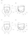
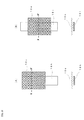
- FIGs. 1 are schematic longitudinal end face views illustrating an example of arrangement of the liquid guide unit.
- the left side corresponds to the front side of the absorbent article.
- the portions other than the liquid guide unit of the absorbent article are omitted.
- FIG. 1(A) illustrates a case of when the wearer is a boy and
- FIG. 1(B) illustrates a case of when the wearer is a girl.
- FIG. 1(A) and FIG. 1(B) The positional relationship of umbilicus U, penis P, scrotum S, clitoris C, meatus urinarius M, introitus I, perineum p, and anus A is as illustrated in FIG. 1(A) and FIG. 1(B) .
- the liquid guide unit 10 is arranged near the meatus urinarius M, and the flow of discharged urine directly collides thereto.
- the liquid guide unit 10 spreads from the vicinity of the meatus urinarius M to the periphery, and hence when urine is discharged, the urine moves from the position where the urine has collided to other positions. Therefore, the absorbent article using the liquid guide unit 10 illustrated in FIG. 1 has an absorber which is excellent in utilization efficiency.
- the distance between the surface of the liquid guide unit and the meatus urinarius is preferably between 0 and 20 mm, and more preferably between 0 and 5 mm.
- the liquid guide unit is a site where the discharged urine first comes into contact, and the position where the urine collides with the liquid guide unit is constant and the function of the liquid guide unit can be easily exhibited if the distance between the surface of the liquid guide unit and the meatus urinarius is in the above-mentioned range.
- the discharging direction and the position barely change if the surface of the liquid guide unit and the meatus urinarius are close to each other, and thus the urine can be stably received and the urine can be uniformly distributed. Further, if the surface of the liquid guide unit and the meatus urinarius are close to each other, the position where the urine collides with the liquid guide unit is less likely to shift even if the body of the wearer moves.
- the surface of the liquid guide unit is preferably brought into contact with the upper surface of the penis from the tip to the root of the penis so that the tip of the penis faces downward.
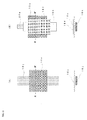
- FIGs. 2 are schematic views of a state in which the absorbent article of the present invention is attached to the wearer.
- FIG. 2(A) and FIG. 2(B) are respectively a front view and longitudinal end face view of the case when the wearer is a boy
- FIG. 2(C) and FIG. 2(D) are respectively a front view and longitudinal end face view of the case when the wearer is a girl.
- the positional relationship of the umbilicus U, penis P, scrotum S, clitoris C, meatus urinarius M, introitus I, perineum p, and anus A of the wearer are as illustrated in FIG.2(A) to FIG. 2(D) .
- the liquid guide unit 10 is preferably arranged spaced apart from the absorber 14 (non-contact state).
- the flow of discharged urine can be supplied to the target site of the absorber in a controlled state by the liquid guide unit by maintaining the liquid guide unit at a position independent from other components.
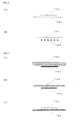
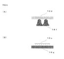
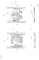
- FIGs. 3 are schematic views illustrating an example of the structure and the function of the liquid guide unit.
- FIG. 3(A) is a perspective view
- FIG. 3(B) and FIG. 3(C) are respectively longitudinal end face views.
- the liquid guide unit 10 illustrated in FIG. 3(A) has a sheet-form (band form), whose width in the left and right direction (X direction) is P, length in the front-rear direction (Y direction) is Q, and thickness in the vertical direction (Z direction) is R.
- X direction left and right direction
- Y direction length in the front-rear direction
- Z direction thickness in the vertical direction
- the urine discharged from the meatus urinarius directly collides to the upper surface of the liquid guide unit, and then moves on the plane defined by the X direction and the Y direction if the liquid guide unit is a liquid guide unit 10a of liquid impermeable type (see FIG. 3(B) ), and moves through a three-dimensionally defined by the X direction, the Y direction, and the Z direction if the liquid guide unit is a liquid guide unit 10b of liquid permeable type (see FIG. 3(C) ).
- the conventional absorbent article has a structure in which such a liquid guide unit is not provided, and a liquid permeable surface sheet is placed on the absorber.
- the discharged urine first permeates through the surface sheet mainly in the Z direction, moves through the interior of the absorber, and diffuses in the X direction and the Y direction. Therefore, the movement range of the urine is narrow.
- a liquid guide unit in sheet form is a liquid guide unit of a preferred structure.
- the liquid guide unit in sheet form preferably has a width P of between 10 and 100 mm, the length Q of between 20 and 200 mm, and the thickness R of between 0.1 and 2 mm.
- the material of the liquid guide unit in sheet form is not particularly limited, and may be formed of film, net, nonwoven fabric, fabric, knitted fabric, or a combination thereof.
- the liquid guide unit may have stretchability at least partially, or may be combined with a stretchable material. In such case, the liquid guide unit exerts delicate follow-up property according to change in body position and movement of the body of the wearer, and hence the position of the liquid guide unit can be always easily maintained constant.
- the liquid guide unit may have cushioning property at least partially, or may be combined with a material having cushioning property.
- the thickness of the liquid guide unit itself or the combination of the liquid guide unit and the material having cushioning property can be easily changed, whereby the liquid guide unit exerts delicate follow-up property according to change in body position and movement of the body of the wearer, and hence the position of the liquid guide unit can be always easily maintained constant.
- a specific structure of the liquid guide unit in sheet form suitably includes a film having openings, bulky nonwoven fabric, and stretchable net.
- the film having openings is a film having numerous openings.
- the film having openings has liquid permeability since the liquid passes through the openings, and has a fluid-distributing function since the liquid moves on the portion other than the openings.
- the film having openings includes a polyolefin-based film including relatively large openings having a diameter of greater than or equal to 0.5 mm and introductory tubes, as proposed by the inventors of the present invention in WO 02/065965 .
- the polyolefin-based film preferably has a thickness of greater than or equal to 1 mm.
- the polyolefin-based film is preferably subjected to surface hydrophilic processing with a surfactant and the like to provide excellent urine adaptation and wettability.
- the bulky nonwoven fabric is a nonwoven fabric having an apparent specific gravity of smaller than or equal to 0.2 g/cm 3 .
- the bulky nonwoven fabric can be obtained through a dry method such as air-through method and spot-bond method.
- the bulky nonwoven fabric has high porosity and also has liquid permeability, and may function as an acquisition layer exhibiting a temporary urine holding function.
- the bulky nonwoven fabric may be used as a sub-layer by being in contact with the top sheet.
- the nonwoven fabric is made of synthetic fiber such as PE fiber, PP fiber, PET fiber, PE/PET bicomponent fiber, and PET/PET bicomponent fiber, the synthetic fiber having a hollow structure and a fineness of preferably greater than or equal to 3d and more preferably greater than or equal to 5d, where an apparent specific gravity is between 0.01 and 0.1 g/cm 3 and thickness under no-load is between 1 and 5 mm.
- synthetic fiber such as PE fiber, PP fiber, PET fiber, PE/PET bicomponent fiber, and PET/PET bicomponent fiber
- the synthetic fiber having a hollow structure and a fineness of preferably greater than or equal to 3d and more preferably greater than or equal to 5d, where an apparent specific gravity is between 0.01 and 0.1 g/cm 3 and thickness under no-load is between 1 and 5 mm.
- the stretchable net is a meshed article having stretchability in at least one direction.
- the stretchability may originate from the stretchability of the material itself of the meshed article, may be provided by the structure of the meshed article (e.g., meshed article in which nylon filament is knitted in stockinet), or may be a combination of both.
- the stretchable net suitably includes a net made of stretchable polyurethane filament, combination-weaved net of nylon and polyurethane filament, stretchable net used in pantyhose for women, or an unidirectional stretchable net (e.g., manufactured by US Conwed Plastics) in which a rubber thread including the PE monofilament (e.g., 30d) for the vertical series and the SEBS elastomer (e.g., 50d) for the horizontal series are combination-weaved.
- a rubber thread including the PE monofilament (e.g., 30d) for the vertical series and the SEBS elastomer (e.g., 50d) for the horizontal series are combination-weaved.
- the liquid guide unit is to be used in combination with a support member.
- the liquid guide unit is preferably supported by the support member from the lower side.
- the support member has a function of enhancing the shape stability of the liquid guide unit, a function of holding the liquid guide unit at a position proximate to the meatus urinarius, a function of blocking a part of the lower surface of the liquid guide unit which is liquid permeable so as to be liquid impermeable, a function of ensuring a space between the liquid guide unit and the absorber, and the like.
- the material used for the support member includes fiber material of thread-form or rope-form, plastic material of film-form or mat-form, and foam made of polyethylene, propylene, urethane or the like having cushioning property.
- Using the sheet-form absorber for the support member as one means for enhancing the absorbing ability is one mode of the present invention.
- Providing stretchability to at least a part of the support member is also one preferred mode.
- the support member has a function of pressing the liquid guide unit against the vicinity of the meatus urinarius of the wearer.
- Examples of the support member having stretchability in at least a part include stretchable net, rubber threads arranged in parallel, stretchable urethane film, and stretchable urethane foam sheet.
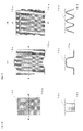
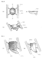
- FIGs. 4 to FIGs. 6 are schematic longitudinal end face views illustrating examples of various combinations of the liquid guide unit and the support member.
- a liquid guide unit 10c is a liquid permeable film having openings
- a support member 16a is a liquid permeable stretchable net.
- the liquid guide unit 10c is a liquid permeable film having openings
- a support member 16b comprises rubber threads arranged in parallel in the left and right direction.
- the support member has the function of pressing the liquid guide unit against the vicinity of the meatus urinarius of the wearer.
- the combinations of the liquid guide unit and the support member illustrated in FIGs. 4 all have liquid permeability.
- a liquid guide unit 10d is a liquid permeable bulky nonwoven fabric
- a support member 16c is a liquid impermeable stretchable urethane film.
- a liquid guide unit 10e is a liquid permeable stretchable net
- a sheet-form absorber used for the absorber functions as a support member 16d.
- the liquid guide unit 10c is a liquid permeable film having openings
- a support member 16e is a liquid impermeable stretchable urethane foam sheet.
- the support member contributes to maintaining the shape of the liquid guide unit, and partially or entirely blocks the lower surface of the liquid guide unit so that such the blocked portion becomes liquid impermeable.
- the liquid guide unit 10d is a bulky nonwoven fabric
- a support member 16f is a molded projecting block (e.g., thickness of 15 mm) of urethane foam having cushioning property.
- the liquid guide unit 10c is a film having openings
- a support member 16g is a net-form foam (e.g., thickness of 10 mm).
- the support member has a function of approaching the liquid guide unit to the vicinity of the meatus urinarius of the wearer, and has a function of ensuring a space between the absorber beneath the support member and the liquid guide unit.
- One preferred mode of the support member is to be connected to the side edge bands on both left and right sides so as to bridge between the side edge bands (see FIG. 16 and FIG. 17 ).
- the liquid guide unit is arranged at the front body part in the internal space formed by the bottom surface part and the side parts of the leak preventer, but is normally connected to other portions of the absorbent article (e.g., skin contact sheet, waist band, urine/feces separating member, side edge bands provided along the ends of the side parts of the leak preventer). If the liquid guide unit is in sheet form, a part of the peripheral edge of the liquid guide unit is preferably not connected to other portions of the absorbent article in order for the liquid guide unit to maintain a constant positional relationship with the meatus urinarius. When being worn, the entire shape of the absorbent article of the present invention constantly changes by the movement and the body position of the wearer.
- the absorbent article e.g., skin contact sheet, waist band, urine/feces separating member, side edge bands provided along the ends of the side parts of the leak preventer.
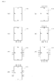
- FIGs. 7 are schematic plan views illustrating connected states and unconnected states of the peripheral edge of the liquid guide unit in sheet form and the other portions of the absorbent article.
- the connection part of the peripheral edge of the liquid guide unit and the other portions of the absorbent article is illustrated with plural parallel lines. Further, in FIGs. 7 , the portion others than the liquid guide unit of the absorbent article are omitted.
- the liquid guide unit 10 illustrated in FIG. 7(A) none of the front end a, the left and right ends b 1 , b 2 and the rear end c is connected to the other portions of the absorbent article.
- the liquid guide unit can be fixed by being connected to other portions of the absorbent article at a central part on the rear side of the liquid guide unit in sheet form (this is the same in each mode illustrated in FIG. 7(B) to FIG. 7(G) ).
- the front end a is connected to another portion of the absorbent article, and the left and right ends b 1 , b 2 and the rear end c are not connected to the other portions of the absorbent article.
- the rear end c is connected to another portion of the absorbent article, and the front end a and the left and right ends b 1 , b 2 are not connected to the other portions of the absorbent article.
- the front end a and the rear end c connected to other portions of the absorbent article, and the left and right ends b 1 , b 2 are not connected to the other portions of the absorbent article.
- the left and right ends b 1 , b 2 are connected to other portions of the absorbent article, and the front end a and the rear end c are not connected to other portions of the absorbent article.
- the left and right ends b 1 , b 2 and the rear end c are connected to other portions of the absorbent article, and the front end a is not connected to other portions of the absorbent article.
- the front end a and the left and right ends b 1 , b 2 are connected to another portion of the absorbent article, and the rear end c is not connected to the other portions of the absorbent article.
- One preferred mode of the absorbent article of the present invention is to further include the urine/feces separating member in the vicinity of the central part in the front-rear direction of the leak preventer, and to have the front body part in the internal space functioning as a urine receiving part and the rear body part in the internal space functioning as a feces receiving part by the urine/feces separating member.
- the urine/feces separating member is not particularly limited as long as it partitions the internal space to the front and the rear, and physically prevents the movement of the urine and the feces.
- an adhesive, rubber, film, foam, nonwoven fabric, and a net-form sheet may be used.
- one preferred mode of the present invention is to have the liquid guide unit connected to the urine/feces separating member.
- the rear end of the liquid guide unit is preferably connected directly or through an intermediation of the support member to the surface of the absorber (or skin contact sheet contacting the absorber) beneath the urine/feces separating member (see FIG. 32(A) ) or at a position behind the urine/feces separating member (see FIG. 28(A) ).
- the urine that moved to the rear side from the position where colliding with the liquid guide unit easily moves to the absorber positioned at the further rear body part.
- One preferred mode of the present invention is to have the liquid guide unit connected to the side edge bands.
- the side edge bands are members provided respectively along the ends of the side parts of the leak preventer, and have a function of maintaining a state closely contacting to the body surface of the wearer.
- Examples of the side edge bands include one having the plural synthetic rubbers, urethane filaments, and the like arranged in parallel, or one having an elastic film of a width of between 2 and 20 mm sandwiched in the two sheets of nonwoven fabric.
- the side edge bands which are connected directly or by connection members to the left and right ends of the liquid guide unit are preferable (see FIGs. 13 to FIGs. 17 , FIGs. 20, and FIGs. 21 ).
- one preferred mode is to provide stretchability to the connection members (see FIG. 13(B) and FIG. 20 ).
- stretchability can be given in a suspended structure like a hammock, whereby the position of the liquid guide unit can be further maintained constant even if the body position or the movement of the wearer changes.
- One preferred mode of the side edge band are to provide stretchability to at least part of the side edge bands. In this mode, a gap is less likely to be formed between the side edge bands and the body surface of the wearer, and thus the close contact therebetween can be more easily maintained.
- One preferred mode of the present invention is to have the liquid guide unit connected to the waist band.
- the waist band forms a waist hole for receiving the waist of the wearer when being worn.
- the waist band is provided at the front end and/or the rear end of the leak preventer. If the waist band is provided at the front end or the rear end of the leak preventer, either one of a hook member or a loop member is provided at the left and right ends of the waist band, and the other one of the hook member or the loop member is provided at the rear part or the front part of the leak preventer.
- the waist hole is formed by connecting the hook member and the loop member.
- the hook members are provided at the left or right ends of one of the waist bands, and the loop members are provided at the left and right ends of the other waist band.
- the waist hole is formed by connecting the hook members and the loop members.
- the waist band has a structure in which 15 urethane filaments (e.g., 470dtex manufactured by DU-PONT TORAY CO., LTD.) are sandwiched between two SMSs (e.g., manufactured by AVGOL Ltd., weight 13g/m 2 ).
- the waist bands are provided at the front end and the rear end of the leak preventer, and the waist bands and the liquid guide unit are connected directly or by a connection member (see FIG. 8(A) , FIGs. 9 , FIG. 10(B) , FIGs. 11 , and FIG. 12(B) ).
- the liquid guide unit is suspended at the front end and the rear end to be in a suspended structure like to a hammock, and the proximate state of the liquid guide unit and the meatus urinarius is stably maintained.
- one preferred mode is to provide stretchability to the connection member (see FIG. 9(B) and FIGs. 11 ).
- further stretchability can be given by the suspended structure like a hammock, whereby the proximate state of the liquid guide unit and the meatus urinarius can be more stably maintained even if the body position or the movement of the wearer changes.
- FIGs. 8 and FIGs. 9 are schematic plan views illustrating combinations of the liquid guide unit formed of a film having openings and the skin contact sheet, and lateral end face views taken along the line X-X' of the plan views.
- the liquid guide unit 10c illustrated in FIG. 8(A) is formed of a rectangular film having openings, and includes skin contact sheets 18a and 18b at the front end and the rear end by way of a connection part (the black painted portion in the figure).
- the connection part may be formed by an adhesive.
- the waist band (not shown) and the front end of the liquid guide unit 10c are connected by the skin contact sheet 18a.
- the liquid guide unit 10c is suspended at the front end and the rear end by the skin contact sheet 18a to be in a suspended structure like a hammock, and the urine that moved on the liquid guide unit 10c of the urine received at the liquid guide unit 10c can be moved to the front side and the rear side, particularly to the rear side, through the skin contact sheet 18a.
- the liquid guide unit 10c illustrated in FIG. 8(B) is formed of a rectangular film having openings, and includes a skin contact sheet 18c extending from the front end to a position behind the rear end on thereon.
- the liquid guide unit 10c and the skin contact sheet 18c are connected by the adhesive and the like at the overlapped portion.
- the waist band (not shown) and the front end of the liquid guide unit 10c are also connected.
- the combination illustrated in FIG. 8(B) has the same effects as those of the combination illustrated in FIG. 8(A) .
- the liquid guide unit 10c illustrated in FIG. 9(A) is formed of a rectangular film having openings, and includes a skin contact sheet 18d extending from a position in front of the front end to a position behind the rear end thereon.
- the waist band (not shown) and the liquid guide unit 10c are connected by the skin contact sheet 18d.
- the liquid guide unit 10c illustrated in FIG. 9(B) is basically the same as the liquid guide unit 10c illustrated in FIG. 9(A) , but differs in that the front end of a skin contact sheet 18e to be combined is connected to a stretchable member 20.
- FIGs. 10 and FIGs. 11 are schematic plan views illustrating combinations of the liquid guide unit formed of a film having openings and the support member, and lateral end face views taken along the line X-X' of the plan views.
- the liquid guide unit 10c illustrated in FIG. 10(A) is formed of a rectangular film having openings, and includes a sheet-form support member 16h extending from the front end to a position behind the rear end beneath the liquid guide unit 10c.
- the liquid guide unit 10c illustrated in FIG. 10(B) is formed of a rectangular film having openings, and includes a sheet-form support member 16i extending from a position in front of the front end to a position behind the rear end beneath the liquid guide unit 10c.
- the waist band (not shown) and the liquid guide unit 10c are connected by the support member 16i.
- the liquid guide unit 10c illustrated in FIG. 11(A) is basically the same as the liquid guide unit illustrated in FIG. 10(B) , but differs in that the sheet-form support member 16j to be combined has stretchability.
- the liquid guide unit 10c illustrated in FIG. 11(B) is basically the same as the liquid guide unit 10c illustrated in FIG. 10(B) , but differs in that the front end of the sheet-form support member 16k to be combined is connected to a stretchable member 20a, and has a skin contact sheet 18f extending from the front end to a position behind the rear end thereon.
- FIGs. 12 are schematic plan views illustrating combinations of the liquid guide unit formed of a bulky nonwoven fabric and the support member, and lateral end face views taken along the line X-X' of the plan views.
- the liquid guide unit 10d illustrated in FIG. 12(A) is formed of a rectangular bulky nonwoven fabric, and includes a sheet-form support member 16h extending from the front end to a position behind the rear end beneath the liquid guide unit 10d.
- the liquid guide unit 10d illustrated in FIG. 12(B) is formed of a rectangular bulky nonwoven fabric, and includes a sheet-form support member 16i extending from a position in front of the front end to a position behind the rear end beneath the liquid guide unit 10d.
- the waist band (not shown) and the liquid guide unit 10d are connected by the sheet-form support member 16i.
- FIGs. 13 and FIGs. 14 are schematic plan views illustrating a combination of the liquid guide unit formed of a film having openings and the side edge bands, and lateral end face views taken along the line X-X' of the plan views.
- the liquid guide unit 10c illustrated in FIG. 13(A) is formed of a rectangular film having openings, and the left and right ends thereof are directly connected to the side edge bands 24 provided along the ends of the side parts (not shown) of the leak preventer.
- the liquid guide unit 10c illustrated in FIG. 13(B) is formed of a rectangular film having openings, and the left and right ends thereof are connected, respectively at two points, to the side edge bands 24 provided along the ends of the side parts (not shown) of the leak preventer by a connection member 26 having stretchability.
- the liquid guide unit 10c illustrated in FIG. 14 is formed of a rectangular film having openings, and the left and right ends thereof are connected to side edge bands 24 provided along the ends of the side parts (not shown) of the leak preventer by a connection member (connection sheet) 26a that does not have stretchability.
- FIGs. 15 are schematic plan views illustrating combinations of the liquid guide unit formed of a bulky nonwoven fabric and the side edge bands, and lateral end face views taken along the line X-X' of the plan views.
- the liquid guide unit 10d illustrated in FIG. 15(A) is formed of a rectangular nonwoven fabric, and the left and right ends thereof are directly connected to the side edge bands 24 provided along the ends of the side parts (not shown) of the leak preventer.
- the liquid guide unit 10d illustrated in FIG. 15(B) is formed of a rectangular nonwoven fabric, and the left and right ends thereof are connected to the side edge bands 24 provided along the ends of the side parts (not shown) of the leak preventer by the connection members (connection sheet) 26a that do not have stretchability.
- FIGs. 16 are schematic plan views illustrating combinations of the liquid guide unit formed of a film having openings, the side edge band, and the support member, and longitudinal end face views taken along the line Y-Y' of the plan views.
- the liquid guide unit 10c illustrated in FIG. 16(A) is formed of a rectangular film having openings, has a sheet-form support member 16h extending from the front end to the position behind the rear end beneath the liquid guide unit 10c and a band-form support member 161 extending from the position on the left of the left end of the liquid guide unit 10c to the position on the right of the right end beneath the support member 16h, and is connected to the side edge bands 24 provided along the ends of the side parts (not shown) of the leak preventer by the band-form support member 161.
- the liquid guide unit 10c illustrated in FIG. 16(B) is formed of a rectangular film having openings, has a sheet-form support member 16m extending from the position on the left of the left end of the liquid guide unit 10c to the position on the right of the right end beneath the liquid guide unit 10c, and is connected to the side edge bands 24 provided along the ends of the side parts (not shown) of the leak preventer by the band-form support member 16m.
- FIGs. 17 are a schematic plan view illustrating a combination of the liquid guide unit formed of a film having openings, the side edge bands, and the support member, and lateral end face views taken along the line X-X' of the plan view.
- the liquid guide unit 10c illustrated in FIG. 17 is formed of a rectangular film having openings, has two band-form support members 16n extending from the positions on the left of the left end of the liquid guide unit 10c to the positions on the right of the right end beneath the liquid guide unit 10c in an X-shape, and is connected to the side edge bands 24 provided along the ends of the side parts (not shown) of the leak preventer by the band-form support members 16n.
- FIGs. 18 are a schematic plan view illustrating a combination of the liquid guide unit formed of a film having openings and the support member, and a lateral end face view taken along the line X-X' of the plan view.
- the liquid guide unit 10c illustrated in FIGs. 18 is formed of a rectangular film having openings, and has a support member 16o made of cylindrical urethane foam beneath the liquid guide unit 10c. In this mode, a space is ensured between the liquid guide unit 10c and the absorber (not shown).
- FIGs. 19 are schematic views illustrating combinations of the liquid guide unit formed of a film having openings and the support member.
- FIGs. 19(A) are a plan view and a lateral end face view taken along the line X-X' of the plan view.
- FIGs. 19(B) are a plan view and a longitudinal end face view taken along the line Y-Y' of the plan view.
- the liquid guide unit 10c illustrated in FIGs. 19(A) is formed of a rectangular film having openings, and the sheet-form absorber used as the absorber is arranged beneath the liquid guide unit 10c so as to have one upward projection at the central part in the left and right direction and functions as the support member 16p.
- 19(B) is formed of a rectangular film having openings, and the sheet-form absorber used as the absorber is arranged beneath the liquid guide unit 10c so as to have three upward projections in the front-rear direction and functions as the support member 16q. In these modes, a space is ensured between the liquid guide unit 10c and the absorber (not shown).
- FIGs. 20 are schematic views illustrating a combination of the liquid guide unit formed of a molded foam body and the side edge bands.
- FIG. 20(A) is a plan view
- FIG. 20(B) is a longitudinal end face view taken along the line Y-Y' of FIG. 20(A)
- FIG. 20(C) is a perspective view.
- the liquid guide unit 10f illustrated in FIGs. 20 is formed of a molded foam body having a recessed surface on the upper side. More specifically, the liquid guide unit includes a bowl-shaped body and a tubular part provided at the rear part of the body, and the interior of the tubular part and the interior of the body are communicated.
- the liquid guide unit 10f is formed of a molded foam body such as foam polypropylene, and is molded by subjecting a foam sheet to, for example, heat press molding.
- the liquid guide unit 10f illustrated in FIGs. 20 is connected to the side edge bands 24 provided along the ends of the side parts (not shown) of the leak preventer by the connection members 26b having stretchability at two points respectively on the left and the right thereof.
- the flow of discharged urine directly collides to the bowl-shaped body, and is collected at the bottom of the body, passes through the tubular part and moves to the absorber.
- FIGs. 21 are schematic perspective views illustrating another combination of the liquid guide unit formed of the molded foam body and the side edge bands.
- the liquid guide unit 10i illustrated in FIG. 21 (A) is formed of a molded foam body having a recessed surface on the upper side. More specifically, the liquid guide unit includes the body forming a shallow recessed surface with small streak-shaped depressions, and a large plate-shaped recessed part provided at the rear part of the body, and a hole is formed at the bottom of the recessed part.
- the liquid guide unit 10i is formed of a molded foam body such as polypropylene foam, and is molded by subjecting a foam sheet to heat press molding.
- 21(A) is connected to the side edge bands 24 provided along the ends of the side parts (not shown) of the leak preventer by the connection members 26b having stretchability at two points respectively on the left and the right.
- the discharged urine moves along the small streak-shaped depressions to be easily collected at the recessed part, and the urine collected at the recessed part moves to the absorber from the hole formed at the bottom.
- the liquid guide unit 10j illustrated in FIG. 21(B) is formed of a molded foam body having a recessed surface on the upper side. More specifically, it is molded to a recessed surface-shape so as to form a bottom at a central part in the left and the right direction.
- the liquid guide unit 10j is formed of a molded foam body such as foam polypropylene, and is molded by subjecting a foam sheet to the heat press molding.
- the liquid guide unit 10j illustrated in FIG. 21(B) is connected to the side edge bands 24 provided along the ends of the side parts (not shown) of the leak preventer by the connection members 26b having stretchability at two points respectively on the left and the right.
- the discharged urine is collected at the bottom of the recess, and the flow of urine with force is moved to the rear side along the recess, and moved from the rear end of the liquid guide unit 10j to the absorber.
- each liquid guide unit illustrated in FIGs. 20, FIG. 21(A) and FIG. 21(B) is configured to match the size of the part under the crotch with the molded foam body, and thus maintains the shape and barely deforms even if sandwiched by both legs, whereby the urine can smoothly move to the rear body part.
- FIGs. 22 are schematic views illustrating the state of movement of urine in one example of the absorbent article of the present invention.
- FIG. 22(A) is a plan view
- FIG. 22(B) is a lateral end face view taken along the line X-X' of FIG. 22(A) .
- FIG. 22(A) is a plan view
- FIG. 22(B) is a lateral end face view taken along the line X-X' of FIG. 22(A) .
- the configuring members of the absorbent article of the present invention only the side parts of the leak preventer, the liquid guide unit, the support member, and the urine/feces separating member are illustrated in FIG. 22(A) , and only the liquid guide unit is illustrated in FIG. 22(B) . As illustrated in FIG.
- the urine discharged from the meatus urinarius M collides to the liquid impermeable liquid guide unit 10a supported by the support member 16 at the X mark, as illustrated with an arrow, moves radially on the surface of the liquid guide unit 10a, and is absorbed at wide range by the absorber (not shown) while moving and diffusing mainly to the lower side from the peripheral edge of the liquid guide unit 10a.
- the urine discharged from the meatus urinarius positioned on the front body part is first absorbed by the absorber at the vicinity thereof, and gradually diffused to the periphery when the relevant site is saturated.
- the diffusion of the urine reaches the distal end of the front body part on the front side but is blocked by the narrowed portion under the crotch on the rear side.
- the diffusion of urine is blocked by the narrowed portion under the crotch and the passage to the rear body part is closed not only in the face-down position and the side-lying position where the absorber at the front body part tends to be used but also in the sitting position or the face-up position where the urine tends to easily move to the rear body part by gravity, and thus the urine can move only up to the vicinity of the anus at the most. Therefore, in the conventional absorbent article, the majority of the rear body part is barely used in any body position.
- the discharged urine is moved particularly in the direction of the rear body part in wide range before being absorbed by the absorber existing near the meatus urinarius, and hence the absorber can be used to about half of the rear body part in the face-down position and to the rear end of the rear body part in the face-up position.
- the utilization efficiency of the entire absorber can be greatly enhanced since the urine can move in a wide range from the front body part to the rear body part in any body position by using the liquid guide unit.
- the urine/feces separating member 28 is arranged to connect a pair of side parts of the leak preventer 12, thereby preventing the urine from mixing with the feces. If the feces receiving part is spaced apart from the absorber thereunder by a feces barrier, the urine and the feces do not mix even if the urine moves to the entire rear body part.
- FIGs. 23 are schematic views illustrating the state of movement of urine in another example of the absorbent article of the present invention.
- FIG. 23(A) is a plan view
- FIG. 23(B) is a lateral end face view taken along the line X-X' of FIG. 23(A) .
- the configuring members of the absorbent article of the present invention only the side parts of the leak preventer, the liquid guide unit, the support member, and the urine/feces separating member are illustrated in FIG. 23(A) , and only the liquid guide unit is illustrated in FIG. 23(B) . As illustrated in FIGs.
- the urine discharged from the meatus urinarius M collides to the liquid permeable liquid guide unit 10b supported by the support member 16 at the X mark, as illustrated with arrows, moves radially on the surface of the liquid guide unit 10b while moving to the lower side, and diffuses and is absorbed at wide range in a short time by the absorber (not shown).
- FIG. 24 is a schematic longitudinal end face view illustrating a state of movement of urine in the absorbent article of the present invention illustrated in FIGs. 23 .
- FIG. 24 illustrates a longitudinal end face view at the central part in the left and right direction of the absorbent article.
- the urine discharged from the meatus urinarius M of the wearer of the absorbent article 1a collides to the liquid permeable liquid guide unit 10b supported by the support member 16 at the mark X and connected to the leak preventer 12, and a part of urine moves to the lower side from the peripheral edge of the liquid guide unit 10b to be absorbed by the absorber 14, and the remaining urine passes through the inside of the liquid guide unit 10b to be absorbed by the absorber 14.
- the urine moves forward on the front side from the portion where the discharged urine collides at the surface of the liquid guide unit 10b, and the urine moves backward at the rear side from the portion.
- the urine moves backward.
- the absorbent article 1a includes the urine/feces separating member 28 and the feces barrier 30
- the urine that moved on the surface of the liquid guide unit 10b is blocked by the urine/feces separating member 28 and the urine that moved backward through the internal space of the leak preventer 14 is blocked by the feces barrier 30, and thus the urine does not move to the feces receiving part R partitioned by the urine/feces separating member 28 and the feces barrier 30, and as a result, the urine and the feces can be separated.
- FIGs. 25 and FIGs. 26 are schematic views illustrating further another example of the absorbent article of the present invention.
- FIG. 25(A) is a plan view
- FIG. 25(B) is a partially enlarged plan view of the liquid guide unit and the skin contact sheet before and while the absorbent article being worn.
- FIG. 26(A) is a longitudinal end face view taken along the line Y-Y' of FIG. 25(A)
- FIG. 26(B) is a lateral end face view taken along the line X 1 -X 1 ' of FIG. 25(A)
- FIG. 26(C) is a lateral end face view taken along the line X 2 -X 2 ' of FIG. 25(A) .
- FIGs. 26 basically includes: a leak preventer 12a having a bottom surface part extending in the front-rear direction and side parts rising upward on both left and right sides of the bottom surface part; an absorber 14 capable of absorbing a body fluid, the absorber containing super absorbent polymer and being placed in an internal space formed by the bottom surface part and the side parts of the leak preventer 12a in at least one layer; and a liquid guide unit 10g placed in a front body part of the internal space, at a position where the flow of discharged urine directly collides therewith, and, when urine is discharged, moving the urine from the position where the urine has collided therewith to other positions.
- the side parts of the leak preventer 12a are folded to be an accordion shape, the internal space is divided to two upper and lower levels, where the absorber 14 is arranged at the lower level and the feces receiving absorber 14a is arranged on the upper side of the absorber 14 at the rear body part of the upper level, the front end thereof being connected to the rear end of the liquid guide unit 10g.
- the feces receiving absorber 14a is a super absorbent sheet obtained through a method of coating the SAP-dispersed slurry on the nonwoven fabric, the SAP layer being arranged on the lower side and the nonwoven fabric layer being arranged on the upper side, and is connected to the inner surface of the leak preventer 12a by adhesive and the like at both left and right ends thereof.
- the front end of the leak preventer 12a is connected with the waist band 32, and the waist band 32 is connected with the front end of the liquid guide unit 10g.
- the rear end of the leak preventer 12a is connected with the waist band 32a, and connecting parts 34 for replaceably connecting to the waist band 32 connected to the front end of the leak preventer 12a are connected to the left and right ends of the waist band 32a.
- a pair of side edge bands 24a are arranged at the left and right side parts of the leak preventer 12a along the ends thereof, and the pair of side edge bands 24a are connected to each other at the central part in the front-rear direction to form an X-shape.
- the front end of the urine/feces separating member 28 is connected to the lower surface of the connection parts of the pair of side edge bands 24a, and the rear end of the urine/feces separating member 28 is connected to the front end of the feces receiving absorber 14a with the rear end of the liquid guide unit 10g.
- the absorbent article 1b has a "two-floor structure" in which the feces receiving absorber 14a is arranged on the leak preventer 12a via the absorber 14 at the rear end to absorb the urine with the absorber 14 on the leak preventer 12a and accommodate the feces on the upper side of the feces receiving absorber 14a.
- the liquid guide unit 10g is formed of a stretchable net (e.g., a rubber filament made of SEBS and EVA, e.g., 60d).
- the skin contact sheet 18g connected to the upper surface of the liquid guide unit 10g is made of nonwoven fabric (e.g., thermal bond nonwoven fabric), where slits in the left and right direction is arranged in parallel.
- the liquid guide unit 10g are not stretched, and the slits of the skin contact sheet 18g are closed (see the left view of FIG. 25(B) ), but while being worn, the liquid guide unit 10g is stretched and the slits of the skin contact sheet 18g are opened (see the right view of FIG. 25(B) ).
- the shape of liquid guide unit 10g can follow the shape of the body surface of the wearer when the absorbent article is worn as it has stretchability.
- the absorbent article 1b includes two sheet-form absorbers including the absorber 14 and the feces receiving absorber 14a. Therefore, the absorbent article 1b is extremely thin with a thickness of between 1/2 and 1/3 compared to the conventional absorbent article using a powder absorber mixed with powdered wood pulp and SAP, but is an absorbent article having an extremely high area utilization efficiency as practically all the portions in the front-rear direction and the vertical direction of the absorber can be used to absorb the urine due to the liquid guide unit. Therefore, the absorbing ability that can sufficiently afford to receive the urine discharge of three or more times is normally provided.
- the absorbent article 1b has an urine/feces separating function due to the urine/feces separating member 28 and the like, and thus diaper rash rarely occurs even if used for a long period of time, and the area which becomes dirty of the buttock of the wearer is small even when the wearer defecates.
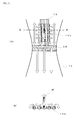
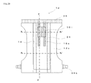
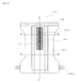
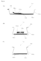
- FIG. 27 and FIGs. 28 are schematic views illustrating further another example of the absorbent article of the present invention.
- FIG. 27 is a plan view
- FIG. 28(A) is a longitudinal end face view taken along the line Y-Y' of FIG. 27
- FIG. 28(B) is a lateral end face view taken along the line X 1 -X 1 ' of FIG. 27
- FIG. 28(C) is a lateral end face view taken along the line X 2 -X 2 ' of FIG. 27 .
- a leak preventer 12b having a bottom surface part extending in the front-rear direction and side parts rising upward on both left and right sides of the bottom surface part; an absorber 14 capable of absorbing a body fluid, the absorber containing super absorbent polymer and placed in an internal space formed by the bottom surface part and the side parts of the leak preventer 12b in at least one layer; and a liquid guide unit 10h placed in a front body part of the internal space, at a position where the flow of discharged urine directly collides therewith, and, when urine is discharged, moving the urine from the position where the urine has collided therewith to other positions.
- the absorber 14 contains super absorbent polymer and wood pulp.
- the skin contact sheet 18h is arranged over the entire surface on the absorber 14.
- the feces receiving absorber 14a is arranged above the skin contact sheet 18h.
- the feces receiving absorber 14a is connected to the inner surface of the leak preventer 12b by adhesive and the like at both left and right ends thereof.
- the left and right side parts of the leak preventer 12b have the ends folded outward, and the pair of side edge bands 24 are arranged along the ends.
- the absorbent article 1c has a "two-floor structure" in which the feces absorber 14a is arranged above the leak preventer 12b via the absorber 14 and the skin contact sheet 18h at the rear part thereof to absorb the urine with the absorber 14 on the leak preventer 12b and accommodate the feces on the upper side of the feces absorber 14a.
- the leak preventer 12b is raised upward at the front end and the rear end.
- Two left and right support members 16r are provided between the front end of the leak preventer 12b and the position slightly behind the urine/feces separating member 28a on the skin contact sheet 18h, and the liquid guide unit 10h is arranged on the two support members 16r to bridge across them.
- the waist band 32b is connected to both left and right sides on the rear side of the leak preventer 12b, and the connecting part 34a for replaceably connecting to the lower side of the front part of the bottom surface part of the leak preventer 12b is connected to the left and right ends of the waist band 32b.
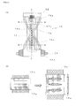
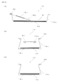
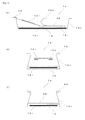
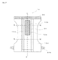
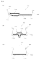
- FIG. 29 and FIGs. 30 are schematic views illustrating further another example of the absorbent article of the present invention.
- FIG. 29 is a plan view
- FIG. 30(A) is a longitudinal end face view taken along the line Y-Y' of FIG. 29
- FIG. 30(B) is a lateral end face view taken along the line X 1 -X 1 ' of FIG. 29
- FIG. 30(C) is a lateral end face view taken along the line X 2 -X 2 ' of FIG. 29 .
- a leak preventer 12c having a bottom surface part extending in the front-rear direction and side parts rising upward on both left and right sides of the bottom surface part; the absorber 14 placed in an internal space formed by the bottom surface part and the side parts of the leak preventer 12c; and a liquid guide unit 10i placed in a front body part of the internal space, at a position where the flow of discharged urine directly collides therewith, and, when urine is discharged, moving the urine from the position where the urine has collided therewith to other positions.
- the absorber 14 is an absorber containing super absorbent polymer and wood pulp and wrapped with a tissue paper, for absorbing body fluid.
- the skin contact sheet 18i is arranged over the entire surface on the absorber 14. Both left and right sides of the leak preventer 12c are raised, and the pair of side edge bands 24 are provided along the ends.
- the waist barrier sheet 36 is connected to the front end of the leak preventer 12c, thereby forming a pocket for preventing urine leakage from the front end of the leak preventer 12c.
- One support member 16s is arranged each on the left and the right at between the waist barrier sheet 36 and substantially the center of the skin contact sheet 18i, and the liquid guide unit 10i is arranged on the upper side of the two support members 16s so as to bridge across them.
- the support members 16s are non-stretchable in the front side of the liquid guide unit 10i and stretchable in the rear side.
- the connecting part 34b for replaceably connecting to the lower side of the front part of the bottom surface part of the leak preventer 12c is connected to both left and right sides of the rear side of the leak preventer 12c.
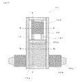
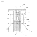
- FIG. 31 and FIGs. 32 are schematic views illustrating further another example of the absorbent article of the present invention.
- FIG. 31 is a plan view
- FIG. 32(A) is a longitudinal end face view taken along the line Y-Y' of FIG. 31
- FIG. 32(B) is a lateral end face view taken along the line X 1 -X 1 ' of FIG. 31
- FIG. 32(C) is a lateral end face view taken along the line X 2 -X 2 ' of FIG. 31 .
- the absorbent article 1e illustrated in FIG. 31 and FIGs. 32 is basically the same as the absorbent article 1d illustrated in FIG. 29 and FIGs.
- the feces receiving sheet 38 made of hydrophobic SMS nonwoven fabric (e.g., weight 15 g/m 2 ) is provided on the skin contact sheet 18i, and both left and right ends of the feces receiving sheet 38 and the inner surface of the leak preventer 12c are partially connected by adhesive and the like so as to leave a non-connected part. Since the non-connected part remains, if loose feces having an extremely high fluidity such as watery feces is discharged, the loose feces moves from both left and right sides of the feces receiving sheet 38 through the non-connection part to the absorber 14 beneath the feces receiving sheet and absorbed thereat.
- hydrophobic SMS nonwoven fabric e.g., weight 15 g/m 2
- the absorbent article 1e has a "two-floor structure" in which the feces receiving sheet 38 is arranged above the leak preventer 12c via the absorber 14 and the skin contact sheet 18i at the rear part thereof to absorb the urine with the absorber 14 on the leak preventer 12c and accommodate the feces on the upper side of the feces receiving sheet 38.
- FIG. 33 and FIGs. 34 are schematic views illustrating further another example of the absorbent article of the present invention.
- FIG. 33 is a plan view
- FIG. 34(A) is a longitudinal end face view taken along the line Y-Y' of FIG. 33
- FIG. 34(B) is a lateral end face view taken along the line X 1 -X 1 ' of FIG. 33
- FIG. 34(C) is a lateral end face view taken along the line X 2 -X 2 ' of FIG. 33 .
- the absorbent article If illustrated in FIG. 33 and FIGs.
- a leak preventer 12c having a bottom surface part extending in the front-rear direction and side parts rising upward on both left and right sides of the bottom surface part; the absorber 14 placed in an internal space formed by the bottom surface part and the side parts of the leak preventer 12c; and a liquid guide unit 10j placed in a front body part of the internal space, at a position where the flow of discharged urine directly collides therewith, and, when urine is discharged, moving the urine from the position where the urine has collided therewith to other positions.
- the absorber 14 is an absorber containing super absorbent polymer and wood pulp and wrapped with a tissue paper, for absorbing body fluid.
- the skin contact sheet 18i is arranged over the entire surface on the absorber 14. Both left and right sides of the leak preventer 12c are raised, and the pair of side edge bands 24 are provided along the ends thereof.
- the waist barrier sheet 36 is connected to the front end of the leak preventer 12c, thereby forming a pocket for preventing urine leakage from the front end of the leak preventer 12c.
- a substantially tube-shaped liquid guide unit 10j is arranged between the waist barrier sheet 36 and substantially the center of the skin contact sheet 18i, and the liquid guide unit 10i is arranged on the central part in the right and left direction.
- the substantially tube-shaped liquid guide unit 10j is formed by folding upward both left and right ends of a rectangular super absorbent sheet having a width of about 50 mm (e.g., MegaThin (registered trademark) manufactured by Japan Absorbent Technology Institute)) to have a C-shaped cross-section (see FIG. 34(B) ), and then being entirely wrapped with the skin contact sheet 18j.
- the liquid guide unit 10j has a thickness of about 3 to 5 mm before absorbing urine, which expands to about 30 to 50 mm after absorbing urine, and thus the proximate state with the meatus urinarius of the wearer can be constantly maintained.
- the liquid guide unit 10j has the vicinity of the front end raised upward slightly without being connected to the skin contact sheet 18i, and the other portions connected to the skin contact sheet 18i (see FIG. 34(A) ).
- the connecting part 34b for replaceably connecting to the lower side of the front part of the bottom surface part of the leak preventer 12c is connected to both left and right sides of the rear side of the leak preventer 12c.
- FIG. 35 and FIGs. 36 are schematic views illustrating further another example of the absorbent article of the present invention.
- FIG. 35 is a plan view
- FIG. 36(A) is a longitudinal end face view taken along the line Y-Y' of FIG. 35
- FIG. 36(B) is a lateral end face view taken along the line X 1 -X 1 ' of FIG. 35
- FIG. 36(C) is a lateral end face view taken along the line X 2 -X 2 ' of FIG. 35
- the absorbent article 1g illustrated in FIG. 35 and FIGs. 36 is basically the same as the absorbent article 1f illustrated in FIG. 33 and FIGs.
- the feces receiving sheet 38 made of hydrophobic SMS nonwoven fabric (e.g., weight 15 g/m 2 ) is provided on the skin contact sheet 18i, and both left and right ends of the feces receiving sheet 38 and the inner surface of the leak preventer 12c are partially connected by adhesive and the like so as to leave a non-connected part. Since the non-connected part remains, if loose feces having an extremely high fluidity such as watery feces is discharged, the loose feces moves from both left and right sides of the feces receiving sheet 38 through the non-connection part to the absorber 14 under the feces receiving sheet 38 thereof and absorbed thereat.
- hydrophobic SMS nonwoven fabric e.g., weight 15 g/m 2
- the absorbent article 1g has a "two-floor structure" in which the feces receiving sheet 38 is arranged above the leak preventer 12c via the absorber 14 and the skin contact sheet 18i at the rear part thereof to absorb the urine with the absorber 14 on the leak preventer 12c and accommodate the feces on the upper side of the feces receiving sheet 38.
- FIG. 37 and FIGs. 38 are schematic views illustrating further another example of the absorbent article of the present invention.
- FIG. 37 is a plan view
- FIG. 38(A) is a longitudinal end face view taken along the line Y-Y' of FIG. 37
- FIG. 38(B) is a lateral end face view taken along the line X 1 -X 1 ' of FIG. 37
- FIG. 38(C) is a lateral end face view taken along the line X 2 -X 2 ' of FIG. 37 .
- a leak preventer 12d having a bottom surface part extending in the front-rear direction and side parts rising upward on both left and right sides of the bottom surface part; the absorber 14b placed in an internal space formed by the bottom surface part and the side parts of the leak preventer 12d; and a liquid guide unit 10k placed in a front body part of the internal space, at a position where the flow of discharged urine directly collides therewith, and, when urine is discharged, moving the urine from the position with which the urine has collided to other positions.
- the absorber 14b is an absorber containing super absorbent polymer and wood pulp and wrapped with a tissue paper, for absorbing body fluid.
- the skin contact sheet 18k is arranged over the entire surface on the absorber 14b. Both left and right sides of the leak preventer 12d are raised, and the pair of side edge bands 24 are provided along the ends thereof.
- the waist barrier sheet 36 is connected to the front end of the leak preventer 12d, thereby forming a pocket for preventing urine leakage from the front end of the leak preventer 12d.
- a V-shaped recessed portion is formed at the middle in the left and right direction of the leak preventer 12d, and the absorber 14b and the skin contact sheet 18k respectively have a shape that lies along the shape of the leak preventer 12d.
- the liquid guide unit 10k and the leak preventer 12e under the liquid guide unit 10k having a shape similar to a sanitary napkin or a urinary pad are provided on the V-shaped recessed portion of the leak preventer 12d via the absorber 14b and the skin contact sheet 18k so as to cover the recessed portion.
- the leak preventer 12e is connected to the skin contact sheet 18k with an adhesive (shaded part of FIG. 38(B) ) at both left and right ends of the lower surface thereof.
- the front end of the leak preventer 12e is raised without being connected to the skin contact sheet 18k, and is arranged to be proximate to the meatus urinarius.
- the liquid guide unit 10k is a rectangular laminated body of the film having openings and the super absorbent sheet (e.g., MegaThin (registered trademark) manufactured by Japan Absorbent Technology Institute)) thereunder, and the bottom surface and both left and right sides thereof are covered by the leak preventer 12e.
- the leak preventer 12e is raised at both left and right sides to form an expandable gather, and thus has a shape similar to a sanitary napkin or a urine pad.
- the absorbent article 1h does not have a feces receiving sheet but can accommodate the feces that flowed out from the rear body part at the recessed portion of the front body part, and thus the possibility the feces contacts the skin of the wearer at the front body part is small.
- the connecting part 34b for replaceably connecting to the lower side of the front portion of the bottom surface part of the leak preventer 12d is connected to the left and right sides on the rear side of the leak preventer 12d.
- the absorbent article corresponding to the absorbent article 1c illustrated in FIGs. 27 and 28 was fabricated in the following manner by hand.
- the absorbent article was fabricated through a method similar to that of Example 1 other than that the liquid guide unit and the support member were not provided.
- the water absorbing capacity and the water-retention amount were measured according to the standard of JIS K7223-1996 "Testing method for water-absorption capacity of super absorbent polymers" with respect to the absorbent article obtained in Example 1.
- the water absorbing capacity was measured by immersing the absorbent article in a normal saline solution for 20 minutes in a bat to absorb water.
- the water retention amount was measured by removing water through centrifugal separation for ten minutes at 1000G after measuring the water-absorbing capacity.
- the thicknesses of the front body part (one absorber layer) and the rear body part (two absorber layers) were measured before and after water absorption as being respectively placed at the middle in the left and right direction of the absorbent article, and the value after water absorption was divided by the value before water absorption to calculate the swelling ratio.
- the measurement result was 440g of water absorbing capacity and 252g of water-retention amount.
- the thickness of the front body part was 3.0 mm before water absorption and 11.0 mm after water absorption, and the swelling ratio was 3.6 times.
- the thickness of the rear body part was 4.1 mm before water absorption and 24.0 mm after water absorption, and the swelling ratio was 5.9 times. Only the absorber using the mixture of pulp and SAP of the related art was arranged at the front body part, and the two-layer absorbers having the absorber and the thin super absorbent sheet was arranged at the rear body part, and thus a large difference was seen between the front body part and the rear body part in the swelling ratio.
- a wearing test was conducted on the absorbent article fabricated in the example. Specifically, healthy babies (total of six babies including three boys and three girls) having normal urinating function and defecating function were made to wear five sheets of absorbent articles (total of thirty sheets), and they were allowed to carry out urination and defecation. The average wearing time, the number of sheets they urinated on, average absorbing capacity of urine, number of sheets from which urine was leaked, number of sheets they defecated on, type of feces, and number of sheets which leaked feces was examined. The results are illustrated in Table 1.
- the usage state of the absorber between boys and girls was similar in the absorbent article of Example 1. This is assumed to be because, although the shape of the local part is different, the direction in which the urine moves after colliding to the liquid guide unit is the same between boys and girls.
- the absorbent article of Comparative Example 1 on the other hand, the rear body part was barely used in boys and girls, and the use concentrated in the front body part for boys and the central part for girls. Therefore, it can be seen that the difference in the used area of the absorber of boys and girls is eliminated by arranging the liquid guide unit. It can also be seen that the utilization efficiency of the absorber was enhanced.
- substantially the entire amount of urine moved to the absorber of the rear body part and the feces receiving absorber similarly to the case of boys.
- how to move the urine to the absorber becomes a problem to be solved in the absorbent article designed to separate the absorber and the body surface during wear in order to avoid the urine and the feces from contacting the body surface of the wearer, but such problem is resolved as substantially the entire amount moved to the absorber of the rear body part and the feces receiving absorber by the liquid guide unit in the absorbent article of Example 1.
- the movement of the urine to the rear body part past the crotch part occurs not only in the face-up position at which the urine relatively easily moves to the rear body part but also in the standing position, the sitting position and the like, and the urine was sufficiently absorbed at the rear body part.
- the surface of the liquid guide unit after use was barely wet, substantially the entire amount of discharged urine moved to the absorber and the feces receiving absorber, and reached the rear ends thereof.
- the absorbent article of the present invention excels in utilization efficiency of the absorber regardless of whether it is used by a boy or a girl, and is less likely to cause leakage, and excels in urine/feces separating function.
Applications Claiming Priority (1)
| Application Number | Priority Date | Filing Date | Title |
|---|---|---|---|
| PCT/JP2006/326274 WO2008081549A1 (ja) | 2006-12-28 | 2006-12-28 | 吸収体物品 |
Publications (1)
| Publication Number | Publication Date |
|---|---|
| EP2098202A1 true EP2098202A1 (de) | 2009-09-09 |
Family
ID=39588239
Family Applications (1)
| Application Number | Title | Priority Date | Filing Date |
|---|---|---|---|
| EP06843652A Withdrawn EP2098202A1 (de) | 2006-12-28 | 2006-12-28 | Saugfähiger artikel |
Country Status (5)
| Country | Link |
|---|---|
| US (1) | US9119750B2 (de) |
| EP (1) | EP2098202A1 (de) |
| JP (1) | JP5138610B2 (de) |
| CN (1) | CN101568315B (de) |
| WO (1) | WO2008081549A1 (de) |
Cited By (1)
| Publication number | Priority date | Publication date | Assignee | Title |
|---|---|---|---|---|
| WO2013003200A1 (en) * | 2011-06-29 | 2013-01-03 | Protective Diaper, Llc | Protective diapering system |
Families Citing this family (6)
| Publication number | Priority date | Publication date | Assignee | Title |
|---|---|---|---|---|
| US9119749B2 (en) | 2011-06-29 | 2015-09-01 | Protective Diaper, Llc | Absorbent article and a method of forming and using |
| US20150164706A1 (en) * | 2012-07-12 | 2015-06-18 | Chaim Ben Natan | Anti-irritant disposable diaper |
| JP6213877B2 (ja) * | 2014-09-29 | 2017-10-18 | 大王製紙株式会社 | パンツタイプ使い捨ておむつ |
| US20180116861A1 (en) * | 2016-10-27 | 2018-05-03 | Kerstin Gilberg | Undergarment pad |
| CN107981986B (zh) * | 2017-12-29 | 2023-04-04 | 广东茵茵股份有限公司 | 一种隔离型纸尿裤及其生产方法 |
| JP2024027894A (ja) * | 2022-08-19 | 2024-03-01 | ユニ・チャーム株式会社 | 吸収性物品包装体、及び、吸収性物品包装体のパッケージ |
Family Cites Families (31)
| Publication number | Priority date | Publication date | Assignee | Title |
|---|---|---|---|---|
| US3227162A (en) * | 1963-07-12 | 1966-01-04 | Machuca Everardo Aguirre | Urine receiver device for a female child |
| US4681577A (en) * | 1983-09-23 | 1987-07-21 | Personal Products Company | Disposable urinary and fecal waste containment product |
| US4778459A (en) * | 1985-03-08 | 1988-10-18 | Fuisz Richard C | High absorbency diaper with composite absorbent layer |
| US4781713A (en) * | 1987-06-10 | 1988-11-01 | Sherwood Medical Company | Incontinence pad for females |
| US4950262A (en) * | 1987-09-29 | 1990-08-21 | Koyo Disposable Goods Co., Ltd. | Excretion absorbing-and-holding device |
| DE69005659T2 (de) * | 1989-02-08 | 1994-05-05 | Kao Corp | Saugfähiger Artikel. |
| CA2054029C (en) | 1991-07-17 | 1998-05-19 | Louise Cynthia Ellis Coe | Absorbent article exhibiting improved fluid management |
| US5618279A (en) * | 1993-05-19 | 1997-04-08 | Edward S. Pudlo | Medical protection device for males |
| JP2757931B2 (ja) | 1993-05-26 | 1998-05-25 | 株式会社日本吸収体技術研究所 | テープレス形吸収体製品およびその製造方法 |
| JP2580205Y2 (ja) * | 1993-11-26 | 1998-09-03 | ユニ・チャーム株式会社 | 使い捨てトレーニングパンツ |
| SE502548C2 (sv) | 1994-03-18 | 1995-11-13 | Moelnlycke Ab | Absorberande artikel, såsom en blöja, innefattande sidobarriärer i form av längsgående flikar förbundna med ett inre vätskegenomsläppligt höljeskikt |
| SE502549C2 (sv) | 1994-03-18 | 1995-11-13 | Moelnlycke Ab | Absorberande artikel, såsom en blöja, innefattande ett öppningsförsett toppskikt |
| SE508407C2 (sv) * | 1994-09-16 | 1998-10-05 | Sca Hygiene Prod Ab | Absorberande artikel |
| US5853403A (en) * | 1994-10-25 | 1998-12-29 | Kimberly-Clark Worldwide, Inc. | Absorbent article with body contacting liquid control member |
| JP3947985B2 (ja) | 1997-05-15 | 2007-07-25 | 株式会社日本吸収体技術研究所 | チューブ状吸収体およびそれを備えた吸収体製品 |
| US6989005B1 (en) * | 1997-03-27 | 2006-01-24 | The Procter & Gamble Company | Absorbent articles having removable components |
| JP3406205B2 (ja) | 1997-10-08 | 2003-05-12 | ユニ・チャーム株式会社 | 使い捨ておむつ |
| JP3375282B2 (ja) * | 1998-05-08 | 2003-02-10 | ユニ・チャーム株式会社 | 使い捨ておむつ |
| JP2000271170A (ja) | 1999-03-25 | 2000-10-03 | Uni Charm Corp | 表面構造体を有する吸収性物品 |
| SE9904202A0 (sv) * | 1999-11-18 | 2001-05-19 | Sca Hygiene Prod Ab | Andningsbart absorberande alster med vätsketätt skikt endast inom vätskelagringsområdet |
| JP4090202B2 (ja) | 2001-01-10 | 2008-05-28 | 王子製紙株式会社 | 吸収性物品 |
| AU2001267863A1 (en) * | 2000-06-29 | 2002-01-08 | Japan Absorbent Technology Institute | Absorber product |
| JP4840895B2 (ja) | 2001-02-20 | 2011-12-21 | 株式会社日本吸収体技術研究所 | 液体分配ユニットとそれを備えた吸収体製品 |
| US20030093045A1 (en) * | 2001-11-13 | 2003-05-15 | Erdman Carol L. | Absorbing article having zoned areas of hydrophilicity |
| US7438707B2 (en) * | 2001-12-28 | 2008-10-21 | Kimberly-Clark Worldwide, Inc | Absorbent articles with absorbent pad gapping |
| US20040204697A1 (en) * | 2003-04-11 | 2004-10-14 | Litvay John D. | Absorbent articles containing absorbent cores having at least one outer layer containing microwells |
| MXPA05006219A (es) * | 2002-12-10 | 2005-09-08 | Japan Absorbent Tech Inst | Producto absorbente con revestimiento superficial no permeable. |
| JP4392170B2 (ja) * | 2003-01-17 | 2009-12-24 | ユニ・チャーム株式会社 | 使い捨ておむつ |
| JP3923490B2 (ja) * | 2004-08-19 | 2007-05-30 | 株式会社日本吸収体技術研究所 | 吸収体物品 |
| JP3954060B2 (ja) * | 2004-10-22 | 2007-08-08 | 株式会社日本吸収体技術研究所 | 吸収体物品 |
| JP2006300317A (ja) | 2005-03-22 | 2006-11-02 | Toyo Tire & Rubber Co Ltd | 防振装置 |
-
2006
- 2006-12-28 WO PCT/JP2006/326274 patent/WO2008081549A1/ja active Application Filing
- 2006-12-28 EP EP06843652A patent/EP2098202A1/de not_active Withdrawn
- 2006-12-28 CN CN2006800567951A patent/CN101568315B/zh not_active Expired - Fee Related
- 2006-12-28 US US12/448,206 patent/US9119750B2/en not_active Expired - Fee Related
- 2006-12-28 JP JP2008552006A patent/JP5138610B2/ja not_active Expired - Fee Related
Non-Patent Citations (1)
| Title |
|---|
| See references of WO2008081549A1 * |
Cited By (2)
| Publication number | Priority date | Publication date | Assignee | Title |
|---|---|---|---|---|
| WO2013003200A1 (en) * | 2011-06-29 | 2013-01-03 | Protective Diaper, Llc | Protective diapering system |
| US8870840B2 (en) | 2011-06-29 | 2014-10-28 | Protective Diaper, Llc | Protective diapering system |
Also Published As
| Publication number | Publication date |
|---|---|
| JP5138610B2 (ja) | 2013-02-06 |
| US20090270828A1 (en) | 2009-10-29 |
| CN101568315B (zh) | 2013-08-07 |
| CN101568315A (zh) | 2009-10-28 |
| WO2008081549A1 (ja) | 2008-07-10 |
| US9119750B2 (en) | 2015-09-01 |
| JPWO2008081549A1 (ja) | 2010-04-30 |
Similar Documents
| Publication | Publication Date | Title |
|---|---|---|
| JP4972335B2 (ja) | 吸収体物品 | |
| EP2014269B1 (de) | Saugfähiges Produkt | |
| EP2826451B1 (de) | Absorberartikel | |
| CN101917948B (zh) | 一次性吸收性物品 | |
| EP2098202A1 (de) | Saugfähiger artikel | |
| RU2396930C2 (ru) | Поглощающее изделие | |
| JP6399304B2 (ja) | 吸収性物品 | |
| EP2898864B1 (de) | Saugfähiger artikel mit neuartigen beinabschlüssen | |
| JP2010119741A (ja) | 吸収性物品 | |
| EP1712214A1 (de) | Saugfähiger artikel | |
| US10470942B2 (en) | Absorbent article and production method thereof | |
| JP4952907B2 (ja) | 高吸水性複合シートおよび吸収体物品 | |
| CN101378713A (zh) | 吸收体物品 | |
| JPH11216162A (ja) | 吸収性物品 | |
| US11617692B2 (en) | Absorbent article including a conformance zone which includes absorbent clusters | |
| JP6705103B2 (ja) | 吸収性物品 | |
| EP2792338A1 (de) | Saugfähiger artikel | |
| US20210353475A1 (en) | Multiple access in a wireless communication system | |
| JP6200659B2 (ja) | 体液受容キャナルを持つ吸収体物品 | |
| JP2022089469A (ja) | 吸収性物品 | |
| WO2021015650A1 (en) | An absorbent article comprising a conformance zone with a plurality of absorbent clusters. |
Legal Events
| Date | Code | Title | Description |
|---|---|---|---|
| PUAI | Public reference made under article 153(3) epc to a published international application that has entered the european phase |
Free format text: ORIGINAL CODE: 0009012 |
|
| 17P | Request for examination filed |
Effective date: 20090625 |
|
| AK | Designated contracting states |
Kind code of ref document: A1 Designated state(s): AT BE BG CH CY CZ DE DK EE ES FI FR GB GR HU IE IS IT LI LT LU LV MC NL PL PT RO SE SI SK TR |
|
| DAX | Request for extension of the european patent (deleted) | ||
| STAA | Information on the status of an ep patent application or granted ep patent |
Free format text: STATUS: THE APPLICATION IS DEEMED TO BE WITHDRAWN |
|
| 18D | Application deemed to be withdrawn |
Effective date: 20110701 |