EP2096708A1 - Kraftfahrzeugantenne, insbesondere für den Empfang von terrestrischen und/oder Satelliten-Funksignalen - Google Patents
Kraftfahrzeugantenne, insbesondere für den Empfang von terrestrischen und/oder Satelliten-Funksignalen Download PDFInfo
- Publication number
- EP2096708A1 EP2096708A1 EP09305160A EP09305160A EP2096708A1 EP 2096708 A1 EP2096708 A1 EP 2096708A1 EP 09305160 A EP09305160 A EP 09305160A EP 09305160 A EP09305160 A EP 09305160A EP 2096708 A1 EP2096708 A1 EP 2096708A1
- Authority
- EP
- European Patent Office
- Prior art keywords
- coil
- antenna
- section
- main
- main section
- Prior art date
- Legal status (The legal status is an assumption and is not a legal conclusion. Google has not performed a legal analysis and makes no representation as to the accuracy of the status listed.)
- Withdrawn
Links
Images
Classifications
-
- H—ELECTRICITY
- H01—ELECTRIC ELEMENTS
- H01Q—ANTENNAS, i.e. RADIO AERIALS
- H01Q9/00—Electrically-short antennas having dimensions not more than twice the operating wavelength and consisting of conductive active radiating elements
- H01Q9/04—Resonant antennas
- H01Q9/30—Resonant antennas with feed to end of elongated active element, e.g. unipole
- H01Q9/32—Vertical arrangement of element
- H01Q9/36—Vertical arrangement of element with top loading
-
- H—ELECTRICITY
- H01—ELECTRIC ELEMENTS
- H01Q—ANTENNAS, i.e. RADIO AERIALS
- H01Q1/00—Details of, or arrangements associated with, antennas
- H01Q1/36—Structural form of radiating elements, e.g. cone, spiral, umbrella; Particular materials used therewith
-
- H—ELECTRICITY
- H01—ELECTRIC ELEMENTS
- H01Q—ANTENNAS, i.e. RADIO AERIALS
- H01Q1/00—Details of, or arrangements associated with, antennas
- H01Q1/36—Structural form of radiating elements, e.g. cone, spiral, umbrella; Particular materials used therewith
- H01Q1/38—Structural form of radiating elements, e.g. cone, spiral, umbrella; Particular materials used therewith formed by a conductive layer on an insulating support
Definitions
- the present invention relates to an antenna for a motor vehicle.
- this antenna is adapted for receiving circularly polarized radio signals that are circularly right and / or left in a determined wavelength band and having an opening angle at 3dB (angular range for which the gain is between a maximum gain equal to about 4dBi and said maximum gain subtracted by 3 dB) ranging from about 15 ° to about 45 ° with respect to the horizon.
- 3dB angular range for which the gain is between a maximum gain equal to about 4dBi and said maximum gain subtracted by 3 dB
- the present antenna is also suitable for receiving linearly polarized terrestrial radio signals vertically in the same wavelength band as for satellite applications, although the gain between 0 ° and 15 ° with respect to the horizon is less (between 0 and -4 dBi) at the useful angle gain for satellite applications (> 15 ° with respect to the horizon).
- the shape of the radiation pattern and the radiated gain value of an antenna are very important parameters to obtain a good operation.
- Wired antennas are well suited for land mobile communications because they have omnidirectional radiation in a horizontal plane for low elevation angles (typically between 0 ° and 15 ° with respect to the horizon) .
- Planar antennas patch or reflector antenna (parabola) are adapted for satellite communications (15-45 °) because they have narrow radiation patterns that increase the gain on a low solid angle.
- This device can be mechanical, as on parables, or with an antenna array misalignment (often the case of planar antennas).
- the radiation of the antenna is omnidirectional for the operation to be independent of the movement of the vehicle.
- no or few antennas make it possible to have a sufficient circular gain in a horizontal section plane with a high elevation angle.
- An object of the present invention is therefore to solve the problem mentioned above with the aid of a reliable solution, compact, inexpensive and simple design.
- the antenna provides a more homogeneous gain for a wide angular range of elevation (about 30 °) compared to a monopole antenna type "whip".
- the radiation pattern also remains approximately circular in a horizontal section plane.
- radiation at the angles elevation less than 15 ° is consistent with land mobile communications (such as FM radio or mobile telephony) with a gain better than -5dBi measured on a 1m side ground plane.
- the antenna according to the present invention is ideally suited for terrestrial and satellite hybrid applications.
- the dimensions of the antenna are reduced, facilitating its integration in multiple locations of the vehicle.
- each secondary branch of the support is extended by a 90 ° elbow directed towards the free end of the main branch so that each secondary section of the conductive track is also extended by a bend directed towards the free end of the main section.
- the dimensions of the antenna are further reduced without causing loss in terms of gain.
- This particular shape, and in particular the use of coils, makes it possible to reduce the length of the antenna relative to the average wavelength of the signal picked up.
- the first coil is disposed substantially in the center of the main section and the coil is disposed just in the immediate vicinity of the junction of the main section with the secondary sections.
- each coil has several meanders.
- the first coil of the main section has six meanders
- the second coil of the main section has three meanders
- each coil of each bend has five meanders.
- the antenna according to the present invention is adapted for receiving an L-band signal for application at frequencies between about 1400 MHz to 1600 MHz, with a maximum bandwidth of 40 MHz.
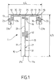
- FIG. figure 1 is a schematic view of the antenna according to the present invention
- the antenna 1 comprises a support 10 having a relative permittivity of about 4.4 and having a thickness of about 1.6 millimeters.
- This substrate is made for example of FR4 epoxy glass of known type.
- the support 10 has a T shape and comprises a main branch 11 and two secondary branches 12 perpendicular to the main branch 11.
- a track 20 of about 1 millimeter wide electrically conductive material, such as copper is printed on the support 10.
- This track 20 defines an aerial which forms the signal receiver.
- This aerial 20, also T-shaped, has a main section 21 and two secondary sections 22 which marry the secondary branches 12 of the support.
- the main section 21 of the track 20 measures substantially ⁇ / 3 while each of the secondary sections 22 measures ⁇ / 8, ⁇ being the wavelength of the average frequency of the signal for which the antenna is adapted, for example between 1470 MHz to 1510 MHz, with a maximum bandwidth of 40 MHz.
- Each secondary branch 12 of the support 10 is extended by a bend 13 at 90 ° directed towards the free end 11a of the main branch 11 so that each secondary section 22 of the track conductive 20 is also extended by a bend 23 directed towards the free end 21a of the main section 21.
- the conductive track 20 comprises, starting from the free end 21a of the main section 21, a first straight strand 31, a first coil 32, a second straight strand 33, and a second coil 34.
- the first serpentine 32 is disposed substantially in the center of the main section 21 and the second coil 34 is disposed in the immediate vicinity of the junction 25 of the main section 21 with the secondary sections 22.
- each secondary section 22 comprises, starting from the junction 25 with the main section 21, a third straight strand 35 which ends substantially at the junction with the elbow 23, and a third coil 36 which ends at the free end 23a of the elbow 23.
- the first coil 32 of the main section 21 has six meanders
- the second coil 34 of the main section has three meanders
- each coil 36 of each bend 23 has five meanders.
- the antenna according to the present invention operates on the principle of a monopole antenna whose height is not a quarter of the average wavelength, as is the case for most applications, especially in the automotive field, but three-quarter wave.
- the addition of the horizontal bar (the branches) thus disrupts the radiation pattern and make it homogeneous over a larger angular range even if the gain is lower.
- Satellite communications are carried by circularly polarized signals (right or left).
- the antenna of the present invention mainly receives signals polarized in a straight line. Since a circularly polarized signal can be broken down into two linearly polarized signals (vertically and horizontally) of the same amplitude (but 90 ° out of phase), the antenna also has the characteristic that it can simultaneously receive circular polarized satellite signals. right and left. However, the gain of the antenna in this mode of operation is degraded by 3dB (because the antenna receives only the vertical component of the satellite signal). But since the gain of the antenna is relatively high (> 4dBi in linear polarization), this antenna is suitable for most satellite applications.
- the antenna sees its dimensions reduced in both directions but it retains the same properties and in particular the shape of its radiation pattern.
- the meanders reduce the stationary wave ratio (TOS) from 10 (antenna without meandering) to 3, which facilitates the operation of the antenna with a circuit adapted to 50 Ohms.
- TOS stationary wave ratio
- this antenna also makes it possible to perform both functions with a single aerial, while remaining within acceptable operating standards.
- This antenna can be realized with simple methods of engraving on printed circuits. It is therefore particularly cheap and produced in large quantities, which is a significant advantage in the automotive equipment industry.
- the number of meanders per coil can vary as soon as the sizing criteria with respect to the average wavelength of the signal picked up are respected.
Landscapes
- Details Of Aerials (AREA)
- Variable-Direction Aerials And Aerial Arrays (AREA)
Applications Claiming Priority (1)
| Application Number | Priority Date | Filing Date | Title |
|---|---|---|---|
| FR0851109A FR2928037B1 (fr) | 2008-02-21 | 2008-02-21 | Antenne pour vehicule automobile, en particulier pour la reception de signaux radio terrestre et/ou satellites. |
Publications (1)
| Publication Number | Publication Date |
|---|---|
| EP2096708A1 true EP2096708A1 (de) | 2009-09-02 |
Family
ID=39865068
Family Applications (1)
| Application Number | Title | Priority Date | Filing Date |
|---|---|---|---|
| EP09305160A Withdrawn EP2096708A1 (de) | 2008-02-21 | 2009-02-19 | Kraftfahrzeugantenne, insbesondere für den Empfang von terrestrischen und/oder Satelliten-Funksignalen |
Country Status (2)
| Country | Link |
|---|---|
| EP (1) | EP2096708A1 (de) |
| FR (1) | FR2928037B1 (de) |
Citations (4)
| Publication number | Priority date | Publication date | Assignee | Title |
|---|---|---|---|---|
| GB2323476A (en) * | 1997-03-20 | 1998-09-23 | David Ganeshmoorthy | Communication antenna |
| DE19961488A1 (de) * | 1999-12-20 | 2001-06-21 | Siemens Ag | Antenne für ein Kommunikationsendgerät |
| EP1717902A1 (de) * | 2005-04-20 | 2006-11-02 | Wistron NeWeb Corp. | Planare Monopolantennen |
| EP1783863A1 (de) * | 2005-11-08 | 2007-05-09 | M/A-Com, Inc. | Mit Dachkapazitäten belastete multiband Monopolantenne |
-
2008
- 2008-02-21 FR FR0851109A patent/FR2928037B1/fr not_active Expired - Fee Related
-
2009
- 2009-02-19 EP EP09305160A patent/EP2096708A1/de not_active Withdrawn
Patent Citations (4)
| Publication number | Priority date | Publication date | Assignee | Title |
|---|---|---|---|---|
| GB2323476A (en) * | 1997-03-20 | 1998-09-23 | David Ganeshmoorthy | Communication antenna |
| DE19961488A1 (de) * | 1999-12-20 | 2001-06-21 | Siemens Ag | Antenne für ein Kommunikationsendgerät |
| EP1717902A1 (de) * | 2005-04-20 | 2006-11-02 | Wistron NeWeb Corp. | Planare Monopolantennen |
| EP1783863A1 (de) * | 2005-11-08 | 2007-05-09 | M/A-Com, Inc. | Mit Dachkapazitäten belastete multiband Monopolantenne |
Also Published As
| Publication number | Publication date |
|---|---|
| FR2928037B1 (fr) | 2010-03-26 |
| FR2928037A1 (fr) | 2009-08-28 |
Similar Documents
| Publication | Publication Date | Title |
|---|---|---|
| EP2441117B1 (de) | Multibandantenne mit kreuzpolarisation | |
| EP3669422B1 (de) | Patch-antenne mit zwei verschiedenen strahlungsmodi mit zwei getrennten arbeitsfrequenzen, vorrichtung mit einer solchen antenne | |
| EP0899814B1 (de) | Strahlende Struktur | |
| EP0520851B1 (de) | Antennenkombination für den Empfang von Signalen von Satelliten und Bodenstationen, insbesondere für den Empfang von digitalen Ton-Rundfunksignalen | |
| FR2960710A1 (fr) | Element rayonnant a double polarisation d'antenne multibande | |
| EP1589608A1 (de) | RF kompakte Antenne | |
| EP1073143A1 (de) | Dualpolarisierte gedruckte Antenne und entsprechende Gruppenantenne | |
| FR2800920A1 (fr) | Dispositif de transmission bi-bande et antenne pour ce dispositif | |
| FR2819109A1 (fr) | Antenne multi-bandes pour appareils mobiles | |
| EP2673842A1 (de) | Wellenleiterantenne mit ringförmigen schlitzen | |
| EP4012839A1 (de) | Antennennetz mit gerichteter strahlung | |
| WO2003061062A1 (fr) | Dispositif pour la reception et/ou l'emission d'ondes electromagnetiques a diversite de rayonnement | |
| EP1516393B1 (de) | Doppelpolarisations-doppelbandstrahlungseinrichtung | |
| CA2800952C (fr) | Antenne compacte large bande a tres faible epaisseur et a double polarisations lineaires orthogonales operant dans les bandes v/uhf | |
| EP2096708A1 (de) | Kraftfahrzeugantenne, insbesondere für den Empfang von terrestrischen und/oder Satelliten-Funksignalen | |
| WO2017171532A2 (fr) | Originale antenne micro-ruban multicouche pour les televisions par satellites dans la bande x | |
| FR2930844A1 (fr) | Antenne rf d'emission et/ou de reception comportant des elements rayonnants excites par couplage electromagnetique sans contact | |
| EP3692598B1 (de) | Antenne mit teilweise gesättigtem dispersivem ferromagnetischem substrat | |
| WO2012104433A1 (fr) | Système d'antenne à polarisation circulaire et lecteur d'étiquette radiofréquence comportant un tel système | |
| FR3013909A1 (fr) | Cornet, antennaire elementaire, structure antennaire et procede de telecommunication associes | |
| EP3902059B1 (de) | Breitband-richtantenne mit longitudinalwellen-übertragung | |
| EP3537540B1 (de) | Elektromagnetische entkoppelung | |
| EP2889955B1 (de) | Kompaktantennenstruktur für Telekommunikationen über Satelliten | |
| FR2911998A1 (fr) | Antenne large bande | |
| WO2016139403A1 (fr) | Structure antennaire omnidirectionnelle large bande |
Legal Events
| Date | Code | Title | Description |
|---|---|---|---|
| PUAI | Public reference made under article 153(3) epc to a published international application that has entered the european phase |
Free format text: ORIGINAL CODE: 0009012 |
|
| AK | Designated contracting states |
Kind code of ref document: A1 Designated state(s): AT BE BG CH CY CZ DE DK EE ES FI FR GB GR HR HU IE IS IT LI LT LU LV MC MK MT NL NO PL PT RO SE SI SK TR |
|
| AX | Request for extension of the european patent |
Extension state: AL BA RS |
|
| STAA | Information on the status of an ep patent application or granted ep patent |
Free format text: STATUS: THE APPLICATION HAS BEEN WITHDRAWN |
|
| 18W | Application withdrawn |
Effective date: 20091218 |