EP2096606A1 - Banknote processing device - Google Patents
Banknote processing device Download PDFInfo
- Publication number
- EP2096606A1 EP2096606A1 EP06835181A EP06835181A EP2096606A1 EP 2096606 A1 EP2096606 A1 EP 2096606A1 EP 06835181 A EP06835181 A EP 06835181A EP 06835181 A EP06835181 A EP 06835181A EP 2096606 A1 EP2096606 A1 EP 2096606A1
- Authority
- EP
- European Patent Office
- Prior art keywords
- banknote
- transport
- emergency
- storing
- banknotes
- Prior art date
- Legal status (The legal status is an assumption and is not a legal conclusion. Google has not performed a legal analysis and makes no representation as to the accuracy of the status listed.)
- Withdrawn
Links
Images






Classifications
-
- G—PHYSICS
- G07—CHECKING-DEVICES
- G07D—HANDLING OF COINS OR VALUABLE PAPERS, e.g. TESTING, SORTING BY DENOMINATIONS, COUNTING, DISPENSING, CHANGING OR DEPOSITING
- G07D11/00—Devices accepting coins; Devices accepting, dispensing, sorting or counting valuable papers
- G07D11/20—Controlling or monitoring the operation of devices; Data handling
-
- G—PHYSICS
- G07—CHECKING-DEVICES
- G07D—HANDLING OF COINS OR VALUABLE PAPERS, e.g. TESTING, SORTING BY DENOMINATIONS, COUNTING, DISPENSING, CHANGING OR DEPOSITING
- G07D11/00—Devices accepting coins; Devices accepting, dispensing, sorting or counting valuable papers
- G07D11/20—Controlling or monitoring the operation of devices; Data handling
- G07D11/26—Servicing, repairing or coping with irregularities, e.g. power failure or vandalism
Definitions
- the present invention relates to a banknote handling device that stores banknotes internally, and more particularly to a banknotes handling device that stores bait banknotes separately from banknote that are dispensed in a normal manner.
- banknote handling devices are used to deposit and dispense banknotes.
- banknote handling devices include: for example, a banknote depositing/dispensing machine (see patent document 1) that is placed behind a counter of a financial institution and with which a teller deposits and dispenses cash; and a banknote handling device (see patent document 2) that is connected to a POS (point of sale) register or the like in a supermarket and that automatically dispenses change.
- POS point of sale
- the devices that deposit and dispense banknotes are provided with a banknote storing portion for feeding and storing banknotes.
- a banknote storing portion stores banknotes.
- These storing methods include a stack method in which a stack of banknotes is fed or stored and a winding method in which banknotes are sandwiched between two tapes and wound around a rotary drum (see patent document 3).
- a system is employed in which, if money is required like this, the highest priority is given to human life.
- a system is utilized in which banknotes whose serial numbers or the like is previously recorded are prepared as bait banknotes (hereinafter referred to as "bait money") serving as emergency banknotes and in which, if money is required, the bait money is given so that the highest priority is given to human life and a criminal is pursued.
- a POS point of sale resister
- a clip connected to an alarm switch and that is used with the bait money held by the clip (see patent document 4).
- the switch connected to the clip is turned on, and thus an alarm is activated.
- bait money is stored in one of banknote storing portions for storing banknotes that are deposited and dispensed, and, in case of the emergency described above, the bait money is dispensed as emergency banknotes.
- banknote handling device information such as serial numbers with which banknotes serving as bait money can be identified is previously recorded, and the banknotes for which this information is recorded are stored in a specific banknote storing portion.
- An object of the present invention is to provide a banknote handling device that can dispense bait money accurately and quickly in case off an emergency.
- a banknote handling device including: a plurality of banknotes storing portions storing a banknote; a banknote dispensing portion collecting and stacking a banknote to be dispensed; an emergency banknote storing portion that stores an emergency banknote to be dispensed in case of an emergency and that is disposed in a position different from that of the banknote storing portions; a transport portion transporting the banknote from the banknote storing portions or the emergency banknote storing portion to the banknote dispensing portion; and a control portion controlling transport of the emergency banknote by the transport portion so that, in case of an emergency, the emergency banknote stored in the emergency banknote storing portion is dispensed to the banknote dispensing portion.
- an emergency banknote storing portion that stores an emergency banknote to be dispensed in case of an emergency is disposed in a transport path between banknote storing portions and a banknote outlet, and thus a time period necessary to transport the emergency banknote can be reduced than when money is normally dispensed.
- the path through which the emergency banknote is transported can be decreased in length, it is possible to prevent the occurrence of a failure caused when the emergency banknote is being transported. Even if a failure is detected by a sensor portion when the emergency banknote is transported, irrespective of whether or not the failure occurs, the emergency banknote can be forcibly dispensed, with the result that the emergency banknote can be reliably dispensed in case of an emergency.
- banknote handling device of this embodiment will be described below by way of example, using a banknote dispensing machine.
- the banknote dispensing machine of this embodiment is arranged at a counter of a financial institution such as a bank, more specifically, between two tellers behind the counter.
- FIG. 1 is an external perspective view
- FIG. 2 which is a schematic cross-sectional view
- higher level terminals 2a and 2b operated by the tellers located on the left and right sides are connected to the banknote dispensing machine 1 of this embodiment.
- the higher level terminals 2a and 2b can communicate with the banknote dispensing machine 1.
- the main body of the banknote dispensing machine 1 is configured such that, when an operation surface operated by the tellers is referred to as a front surface 1a and the opposite surface of the front surface 1a is referred to as a rear surface 1b, the main body is uprightly mounted with a narrow width in a lateral direction, a wide depth in a forward and backward direction and a long height in a vertical direction.
- banknote outlets 10a and 10b to which banknotes are dispensed are formed in upper portions of main body side surfaces 1c and 1d, respectively.
- the banknotes that are fed out to the banknote outlets 10a and 10b are taken out by the tellers, who operate the higher level terminals 2a and 2b, respectively.
- the banknote dispensing machine 1 is composed of: an upper unit 1x including a transport path that transports banknotes to the banknote outlets 10a and 10b (see FIG. 1 ); and a lower unit 1y including storing cassettes that store banknotes.
- the banknote outlets 10a and 10b are disposed in mounting positions in the upper unit 1x, in the main body side surfaces 1c and 1d, respectively.
- the banknote outlets 10a and 10b are disposed in the main body side surfaces 1c and 1d, respectively, so as to interpose therebetween an escrow portion 11 to be described later.
- the upper unit 1x is provided with: the escrow portion 11 that temporarily stores banknotes that are fed out to the banknote outlets 10a and 10b; the transport path 12 for transporting banknotes; a reject portion 13 for storing banknotes that fails to be transported satisfactorily due to a transport failure such as double feeding; a bait money storing portion 14 for storing a stack of a plurality of banknotes serving as bait money that is fed out in case of an emergency; a double note detection sensor 15a that detects double feeding in which a stack of two or more banknotes is transported from the lower unit 1y; and position detection sensors 15b to 15e for checking whether or not banknotes are normally transported.
- the transport path 12 disposed in the upper unit 1x includes: a transport path 12a that transports a banknote transported from the lower unit 1y into the upper unit 1x; a transport path 12b that transports a banknote from the bait money storing portion 14 or the transport path 12a to the escrow portion 11; and a transport path 12c that branches off the transport path 12b and that transports a banknote to the reject portion 13.
- the reject portion 13, the escrow portion 11 and the bait money storing portion 14 are disposed from the front surface 1a to the rear surface 1b so as to be positioned in this order.
- the double note detection sensor 15a is disposed around a connection between the transport path 12a, into which a banknote from the lower unit 1y is transported and a transport path 12x in the lower unit 1y.
- the position detection sensor 15b is disposed on the transport path 12a; the position detection sensor 15c is disposed on the transport path 12b.
- the position detection sensor 15d is disposed on the transport path 12b and in front of the transport inlet of the escrow portion 11; the position detection sensor 15e is disposed on the transport path 12b and in front of the transport outlet of the bait money storing portion 14.
- the lower unit 1y is provided with: a plurality of storing cassettes 16a to 16f that store banknotes of different denominations, respectively; the transport path 12x that transports banknotes stored in the storing cassettes 16a to 16f to the upper unit 1x; a communication connector 19a for connection and communication with the higher level terminals 2a and 2b; and a power supply unit 20 that converts an alternating-current power from an external power supply into a direct-current power to feed it to portions of the upper unit 1x and the lower unit 1y.
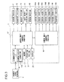
- the banknote dispensing machine 1 of this embodiment is provided with: an upper unit control portion 17 that controls operations of the blocks of the upper unit 1x; a lower unit control portion 18 that controls operations of the blocks of the lower unit 1y; a communication interface 19 that includes the communication connector 19a and through which to communicate with a higher level terminal 2 (equivalent to the higher level terminals 2a and 2b in FIG.
- a memory 21 that stores identification information such as banknote numbers with which banknotes serving as the bait money stored in the bait money storing portion 14 are individually identified, information on the denominations of banknotes stored in the storing cassettes 16a to 16f and the like; an operation portion 22 through which to directly operate the banknote dispensing machine 1; and a display 23 that produces a display showing the current operational state, a detected failure or the like.
- the upper unit control portion 17 controls operations such as for: transporting a banknote by the transport path 12 within the upper unit 1x; feeding, from the escrow portion 11, banknotes out to the banknote outlets 10a and 10b; transferring to a state in which a banknote can be taken out of the reject portion 13; feeding out the bait money from the bait money storing portion 14; and producing a display on a display 23.
- the upper unit control portion 17 also receives a signal from a sensor portion 15 (including the double note detection sensor 15a and the position detection sensors 15b to 15e in FIG. 2 ) to detect a banknote transport failure.
- This upper unit control portion 17 controls the lower unit control portion 18 and communicates with the higher level terminal 2 through the communication interface 19. Moreover, the upper unit control portion 17 receives an input signal generated by the operation of the operation portion 21 and checks the details of the operation.
- the lower unit control portion 18 controlled by the upper unit control portion 17 controls operations such as for: transporting a banknote by the transport path 12x within the lower unit 1y; and feeding out banknotes from the storing cassettes 16a to 16f.
- the lower unit control portion 18 receives a signal from an unillustrated sensor to detect a transport failure within the lower unit 1y, and transmits a result obtained by detecting this transport failure to the upper unit control portion 17.
- the upper unit control portion 17 receives a control signal through the communication interface 19 from the higher level terminal 2 of higher level, and controls operations of the blocks. As a result of the operation portion 22 being directly operated, the upper unit control portion 17 also receives a control signal corresponding to the operation of the operation portion 22, and controls operations of the blocks.
- the upper unit control portion 17 performs an operation to determine, according to the amount of money to be dispensed, the number of banknotes of each denomination to be dispensed. Then, the upper unit control portion 17 checks storage information stored in the memory 21 to select, from the storing cassettes 16a to 16f, storing cassettes corresponding to the denominations of the banknotes to be dispensed. Thereafter, the upper unit control portion 17 controls the lower unit control portion 18 to feed out banknotes to be dispensed from the selected storing cassettes.
- a stack of a plurality of banknotes serving as the bait money stored in the bait money storing portion 14 is fed out to the transport path 12. Then, when this bait money is dispensed, if the upper unit control portion 17 detects a failure based on a signal from the sensor portion 15 (including the position detection sensors 15b to 15e in FIG. 2 ), it stores the details of the failure in the memory 21.
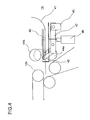
- the bait money storing portion 14 is provided with: a banknote set tray 41 where the bait money 40 is placed; a banknote set detection lever 42 designed such that its curved end protrudes from the surface of the set tray 41 where the bait money 40 is to be placed and comes in contact with the bait money 40 to be placed; a banknote set detection sensor 43 for detecting, from the displacement of the banknote set detection lever 42, whether or not the bait money 40 to be placed is present; feeding rollers 44a and 44b that feed a stack of bait money 40 out to the transport path 12b; a stopper 45 that prevents the bait money 40 from being fed out to the transport path 12b; and a stopper release solenoid 46 that swings the stopper 45 either to prevent the bait money 40 from being transported to the transport path 12b or to allow the bait money 40 to be transported thereto.
- the end of the banknote set detection lever 42 which protrudes from the surface of the set tray 41 where the bait money 40 is to be placed, is pressed by the bait money 40.
- the banknote set detection lever 42 rotates about a position that is far away from the end in contact with the bait money 40 and at which the banknote set detection sensor 43 is disposed.
- the displacement of the banknote set detection lever 42 resulting from the rotation of the banknote set detection lever 42 is detected by the banknote set detection sensor 43, and thus the bait money 40 is found to be placed in the set tray 41. Then, a signal indicating the detection by the banknote set detection sensor 43 is transmitted to the upper unit control portion 17, with the result that the upper unit control portion 17 finds the bait money 40 to be placed in the set tray 41.
- the bait money 40 When the bait money 40 is placed in the set tray 41 as described above, the bait money 40 is sandwiched between the feeding roller 44a fixed to an area below the set tray 41 and the feeding roller 44b that moves vertically so as to remain in contact with the surface of the bait money 40 placed in the set tray 41. Then, the stopper release solenoid 46 holds the stopper 45 in the upper side; the curved end of the stopper 45 protrudes from the surface of the set tray 41 where the bait money 40 is to be placed, and comes in contact with edges of the bait money 40. In this way, the stopper 45 makes contact with the bait money 40, and can thus prevent the bait money 40 from being transported to the transport path 12b.
- the stopper release solenoid 46 is controlled by the upper unit control portion 17 to move the stopper 45 to the lower side. Specifically, the stopper release solenoid 46 swings the stopper 45 such that the curved end of the stopper 45, which protrudes from the surface of the set tray 41 where the bait money 40 is to be placed, is retracted into the lower side. Thus, the protrusion of the stopper 45 in contact with the edges of the bait money 40 disappears form the area between the set tray 41 and the transport path 12b, and accordingly the bait money 40 enters a state where it can be transported to the transport path 12b. Then, the upper unit control portion 17 controls the feeding rollers 44a and 44b to drive them, with the result that a stack of bait money 40 is transported from the set tray 41 to the transport path 12b.
- FIG. 5 is a flowchart showing the main flow of the normal dispensing operation
- FIGS. 6 and 7 are flowcharts showing the operation of detecting a failure in the transport path 12 when money is normally dispensed.
- FIG. 8 is a diagram showing a banknote transport route within the banknote dispensing machine 1;
- FIG. 9 is a diagram showing a banknote transport route in the upper unit 1x.
- the upper unit control portion 17 first performs an operation to determine, according to the amount of money to be dispensed, denominations required and the number of banknotes of the denominations (step 2). Then, based on the storage information stored in the memory 21, storing cassettes that store the banknotes of the denominations required are found among the storing cassettes 16a to 16f, and a banknote feeding flow for switching the operation of feeding out money from the associated cassette is set by the number of banknotes of each denomination (step 3).
- the banknote feeding flow is set and the required number of banknotes of each denomination are fed out from the storing cassette, and the storing cassette is switched to a storing cassette for the subsequent round of feeding.
- the normal dispensing operation corresponding to the set feeding flow is started so that the required number of banknotes of each denomination are fed out on a denomination-by-denomination basis (step 4).
- a banknote is transported from one of the storing cassettes 16a to 16f to the transport path 12x in the lower unit 1y, and is then transported through this transport path 12x to the transport path 12a in the upper unit 1x.
- the upper unit control portion 17 drives the transport path 12c, which branches off the transport path 12b, and the transport path 12c transports, to the reject portion 13, the banknotes transported through the transport path 12a to the transport path 12b.
- banknotes such as one that is caught in the transport path 12 or the transport path 12x and that is thus folded are transported to the reject portion 13.
- the upper unit control portion 17 drives only the transport path 12b, and thus the banknote is directly transported by the transport path 12b to the escrow portion 11.
- the transport path 12b into the escrow portion 11
- the required number of banknotes of each denomination are stacked and stored according to the order of the denominations set by the feeding flow.
- the feeding of a banknote into the escrow portion 11 is supplied to the upper unit control portion 17, the number of banknotes fed into the escrow portion 11 is counted.
- the lower unit control portion 18 switches the storing cassettes from which banknotes are fed out.
- the upper unit control portion 17 first supplies the feeding flow to the lower unit control portion 18. Then, the lower unit control portion 18 feeds banknotes out from the storing cassette 2b one by one.
- the upper unit control portion 17 finds, through the double note detection sensor 15a and the position detection sensors 15b to 15d, that the S2 banknotes are successfully transported to the transport path 12, the lower unit control portion 18 then stops the operation of feeding a banknote out from the storing cassette 16b, and banknotes are fed out from the storing cassette 16a one by one.
- the upper unit control portion 17 detects, from signals from the position detection sensors 15b to 15d disposed in the transport paths 12a and 12b and at the transport inlet of the escrow portion 11 in the upper unit 1x, whether or not a banknote transport failure occurs (step 5).
- the detection of the banknote transport failure from the signals from the position detection sensors 15b to 15d will be described with reference to the flowcharts of FIGS. 6 and 7 .
- the upper unit control portion 17 checks whether or not, as a result of the denomination of banknotes stored in the escrow portion 11 becoming equal to the amount of money to be dispensed, the dispensing operation is completed (step 501). Here, if the dispensing operation is found to be completed (yes), the operation of detecting a transport failure is completed.
- the upper unit control portion 17 detects, based on whether or not the signal from the position detection sensor 15b is present, whether or not a banknote is transported from the transport path 12x to the transport path 12a (step 502).
- the signal from the position detection sensor 15b shows that the banknote is transported to the position where the position detection sensor 15b in the transport path 12a is disposed (yes)
- a time period T1 that is measured by an unillustrated timer is set (step 503).
- This time period T1 is the upper limit of a time period necessary to successfully transport a banknote from the position of the position detection sensor 15b in the transport path 12a to the position of the position detection sensor 15c in the transport path 12b.
- an integral value N1 determined from T1 / ⁇ t1 may be set in step 503, and the integral value N1 may be decremented by one at a time in step 505 to be described later.
- step 503 the time period measured by the timer may be initialized to zero and a time period that has elapsed after the initialization may be measured so that the time period is determined to be equal to the predetermined time period T1 in step 506 to be described later.
- step 504 based on whether or not the signal from the position detection sensor 15c is present, whether or not the banknote is transported from the transport path 12a to the transport path 12b is detected.
- the operation of checking, based on whether or not the signal from the position detection sensor 15b is present, whether or not the banknotes is transported will be repeated in an operation shown in the flowchart of FIG. 7 to be described later.
- step 504 the signal from the position detection sensor 15c shows that the banknote is transported to the position where the position detection sensor 15c in the transport path 12b is disposed (yes)
- step 501 the process moves to step 501 in order to check whether or not the banknotes is successfully transported to the position detection sensor 15c in the transport path 12b. If, in step 502, the signal from the position detection sensor 15b shows that the banknote is not transported to the transport path 12a (no), the process also moves to step 501.
- step 504 the signal from the position detection sensor 15c showing that the banknote is transported to the position where the position detection sensor 15c in the transport path 12b is disposed is not found (no)
- the time period measured by the unillustrated timer is reduced only by the time period ⁇ t1 necessary to perform the operation (step 505), and then whether or not a timeout is reached as a result of the reduced time period becoming zero is checked (step 506). Then, if, in step 506, the time period measured by the unillustrated timer is not zero (no), the process moves to step 504, where the signal from the position detection sensor 15c is checked. If, in step 506, the time period measured by the unillustrated timer becomes zero (yes), the upper unit control portion 17 determines that a banknote transport failure has occurred (step 507), and completes the operation of detecting the transport failure.
- step 511 the dispensing operation is found to continue (no)
- the upper unit control portion 17 first detects, based on whether or not the signal from the position detection sensor 15c is present, whether or not the banknote is transported from the transport path 12a to the transport path 12b (step 512).
- the banknote is found to be transported to the position where the position detection sensor 15c in the transport path 12b is disposed (yes)
- a time period T2 measured by the unillustrated timer is set (step 513)
- the process moves to step 511.
- the time period T2 measured by the unillustrated timer may be either incremented or decremented. Time itself may be measured, or, based on a time period ⁇ t2 during which an operation in steps 514 and 515 to be described later is performed, an integral value N2 determined from T2 / ⁇ t2 may be either decremented or incremented, thereby measuring the time period.
- step 513 the time period T2 is set, based on whether or not a signal from the position detection sensor 15d is present, whether or not the banknote is transported by the transport path 12b to the transport inlet of the escrow portion 11 is checked (step 514).
- the process moves to step 511 in order to confirm whether or not the banknote is successfully transported to the transport inlet of the escrow portion 11.
- the time period measured by the unillustrated timer is reduced only by the time period ⁇ t2 necessary to perform the operation (step 515), and then whether or not a timeout is reached as a result of the reduced time period becoming zero is checked (step 516).
- step 516 If, in step 516, the time period measured by the unillustrated timer is not zero (no), the process moves to step 514, where the signal from the position detection sensor 15d is checked. If, in step 516, the time period measured by the unillustrated timer is zero (yes), the upper unit control portion 17 determines that a banknote transport failure has occurred (step 517), and completes the operation of detecting the transport failure.
- step 5 the operation is performed according to the flowcharts of FIGS. 6 and 7 , and thus the position detection sensors 15b to 15d check whether or not a transport failure occurs in the transport paths including the transport paths 12a and 12b from the transport path 12x in the lower unit to the escrow portion 11. Then, if a transport failure is found (yes), the dispending operation is stopped (step 6), and the display 23 produces a display showing that the transport failure occurs in the transport path (step 7), and then the operation is completed.
- the transport failure display may be produced on the higher level terminals 2a and 2b that are operated.
- step 5 If, in step 5, a failure is not detected in the transport path 12 (no), whether or not the dispensing operation is completed is checked according to whether or not all the banknotes corresponding to the specified amount of money are transported to the escrow portion 11 (step 8). If the dispensing operation is not found to be completed (no), the process moves to step 5, where whether or not a transport failure occurs is checked again, whereas, if the dispensing operation is found to be completed (yes), the transport operation by the transport path 12 and the operation by the lower unit 1y are stopped (step 9).
- step 10 When the transport of a banknote by the transport path 12 and the lower unit 1y is stopped, the banknotes stored in the escrow portion 11 are fed out to either of the banknote outlets 10a and 10b (step 10), and then the normal dispensing operation is completed.
- which one of the banknote outlets 10a and 10b the banknotes are fed out to may be set through the higher level terminals 2a and 2b; which one of the banknote outlets 10a and 10b the banknotes are fed out to may be set through the operation portion 22 .
- the transport path 12c is driven to transport the banknotes to the reject portion 13.
- the transport path 12c is driven to transport the banknote to the reject portion 13.
- step 6 the transport operation is stopped.
- the denomination and the number of banknotes are set based on the input amount of money to be dispensed and then the banknotes are dispensed, banknotes may be dispensed as a result of the denomination and the number of the banknotes being specified through the higher level terminals 2a and 2b or the operation portion 22.
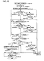
- FIG. 10 is a flowchart showing an operation of dispensing the bait money
- FIG. 11 is a diagram showing a banknote transport route within the banknote dispensing machine 1
- FIG. 12 is a diagram showing a banknote transport route in the upper unit 1x.
- the upper unit control portion 17 sets a time period T3 that is measured by the unillustrated timer (step 102).
- This time period T3 is the upper limit of a time period necessary to successfully transport a banknote from the transport outlet of the bait money storing portion 14 to the transport inlet of the escrow portion 11.
- the time period may be measured by the following procedure: based on a time period ⁇ t3 during which an operation in steps 103, 106, 107 and 110 to 112, etc. to be described later is performed, an integral value N3 determined from T3 / ⁇ t3 is set in step 102, and this integral value N3 is decremented by one at a time, thereby measuring the time period.
- the time period measured by the timer may be initialized to zero and a time period that has elapsed after the initialization of the timer may be measured so that the time period is determined to be equal to the predetermined time period T3.
- the upper unit control portion 17 controls the operations of the bait money storing portion 14 and the transport path 12b to start the operation of dispensing the bait money (step 103). Specifically, the stopper release solenoid 46 releases the state in which the bait money 40 is prevented by the stopper 45 from being transported, then the feeding rollers 44a and 44b are driven and the bait money 40 is fed out and simultaneously the transport operation by the transport path 12b is started.
- the upper unit control portion 17 checks, based on a signal from the position detection sensor 15e, whether or not a stack of banknotes serving as the bait money passes through the position where the position detection sensor 15e is disposed, that is, the transport outlet of the bait money storing portion 14 (step 104). Specifically, the position detection sensor 15e checks whether or not the banknotes serving as the bait money are present in the position where the position detection sensor 15e in the transport path 12b is disposed and then disappear from the position where the position detection sensor 15e in the transport path 12b is disposed. In this way, the banknotes serving as the bait money are found to be transported from the bait money storing portion 14 to the transport path 12b.
- step 104 the stack of banknotes serving as the bait money is not found to pass through (no)
- the time period measured by the unillustrated timer is reduced only by the time period ⁇ t3 necessary to perform the operation (step 105), and then whether or not a timeout is reached as a result of the reduced time period becoming zero is checked (step 106). Then, if, in step 106, the time period measured by the unillustrated timer is not zero (no), the process moves to step 104, where the signal from the position detection sensor 15e is checked. In operations in steps 104 to 106, the position detection sensor 15e checks whether or not the bait money is fed out from the bait money storing portion 14, where the bait money is originally stored.
- the upper unit control portion 17 determines that a banknote transport failure has occurred, and stores information on the transport failure in the memory 21 (step 116).
- the memory 21 stores the information that the transport failure has occurred in the position where the position detection sensor 15e is disposed, that is, the transport outlet of the bait money storing portion 14.
- step 104 based on the signal from the position detection sensor 15e, the stack of banknotes serving as the bait money is found to pass through (yes), even after the stack of banknotes serving as the bait money passes through the position where the position detection sensor 15e is disposed, whether or not a banknote is detected by the position detection sensor 15e is checked (step 107).
- a banknote is detected by the position detection sensor 15e (yes)
- it is determined that not all the bait money passes through and the process moves back to step 104, where whether or not the bait money passes through is checked by the position detection sensor 15e.
- step 108 if a banknote is not detected by the position detection sensor 15e (no), based on the signal from the position detection sensor 15c disposed on the transport path 12b, whether or not the stack of banknotes serving as the bait money pass through the position where the position detection sensor 15c in the transport path 12b is disposed is checked (step 108).
- step 108 the stack of banknotes serving as the bait money is not found to pass through (no)
- steps 105 and 106 the time period measured by the unillustrated timer is reduced only by the time period ⁇ t3 necessary to perform the operation (step 109), and then whether or not a timeout is reached as a result of the reduced time period becoming zero is checked (step 110).
- step 110 whether or not the bait money passes through the transport path 12b in motion is checked by the position detection sensor 15c, and whether or not a banknote failing to be transported is left is also checked by the position detection sensor 15e.
- step 110 the time period measured by the unillustrated timer is not zero (no)
- the process moves to step 107, where the signal from the position detection sensor 15e is checked.
- step 110 the time period measured by the unillustrated timer becomes zero (yes)
- the process moves to step 116, where information on the occurrence of a transport failure in the position where the position detection sensor 15c in the transport path 12b is disposed is stored in the memory 21.
- step 108 based on the signal from the position detection sensor 15c, the stack of banknotes serving as the bait money is found to pass through (yes)
- step 107 whether or not a banknote is detected by the position detection sensor 15e, which has found that the stack of banknotes serving as the bait money had passed through, is checked (step 111). Then, if a banknote is detected by the position detection sensor 15e (yes), the process moves to step 104, where whether or not the bait money passes through is checked by the position detection sensor 15e.
- step 112 whether or not a banknote is detected by the position detection sensor 15c, which has found that the stack of banknotes serving as the bait money had passed through, is checked (step 112).
- step 112 a banknote is detected by the position detection sensor 15c (yes)
- the process moves to step 107, where whether or not the bait money is present is checked by the position detection sensor 15e.
- step 113 a banknotes is not detected by the position detection sensor 15c (no)
- step 113 whether or not the stack of banknotes serving as the bait money passes through the position where the position detection sensor 15d at the transport inlet of the escrow portion 11 is disposed is checked (step 113).
- step 113 If, in step 113, the stack of banknotes serving as the bait money is not found to pass through (no), as in steps 105, 106, 109 and 110, the time period measured by the unillustrated timer is reduced only by the time period ⁇ t3 necessary to perform the operation (step 114), and then whether or not a timeout is reached as a result of the reduced time period becoming zero is checked (step 115).
- step 115 whether or not the bait money is fed into the escrow portion 11, into which the bait money is to be fed, is checked by the position detection sensor 15d, and whether or not a banknote failing to be transported is left is checked by the position detection sensors 15c and 15e.
- step 115 the time period measured by the unillustrated timer is not zero (no)
- the process moves to step 111, where the signal from the position detection sensor 15e is checked. If, in step 115, the time period measured by the unillustrated timer becomes zero (yes), the process moves to step 116, where information on the occurrence of a transport failure at the transport inlet of the escrow portion 11 is stored in the memory 21.
- step 113 based on the signal from the position detection sensor 15d, the stack of banknotes serving as the bait money is found to pass through (yes), or, in step 116, information on transport failures occurring in the positions where the position detection sensors 15c to 15e are disposed is stored in the memory 21, the operation of dispensing the bait money is stopped (step 117). Specifically, in the bait money storing portion 14, the stopper release solenoid 46 moves the stopper 45 to prevent the bait money 40 from being transported and stops the feeding operation by the feeding rollers 44a and 44b. Then, the transport operation by the transport path 12b is stopped.
- step 118 which one of the banknote outlets 10a and 10b the bait money is fed out to may be determined through the higher level terminals 2a and 2b; which one of the banknote outlets 10a and 10b the bait money is fed out to may be determined through the operation portion 22. Alternatively, it is possible to previously determine which one of the banknote outlets 10a and 10b is used on a fixed basis.
- step 119 the contents of the memory 21 show that a transport failure occurs (yes)
- the display 23 produces a display showing that a transport failure occurs in the transport path (step 120), and the operation is completed.
- no transport failure is found (no)
- the bait money is considered to be normally transported, and the operation is completed.
- the display that shows the transport failure in step 120 may be produced on the higher level terminals 2a and 2b that are operated. In this display showing the transport failure, in which one of the positions where the position detection sensors 15c and 15d are disposed the transport failure occurs may be shown. Moreover, the display may show whether the transport failure results from the bait money not passing through or a banknote being left behind.
- the bait money stored in the escrow portion 11 is forcibly dispensed to the either of the banknotes outlets 10a and 10b.
- This predetermined time period may be checked by measuring the predetermined time period after money starts being dispensed, as describe above, or the total of time periods allowable for the bait money to pass through the position of the individual sensors may fall within the predetermined time period.
- the bait money stored in the escrow portion 11 is forcibly dispensed to the either of the banknote outlets 10a and 10b.
- the bait money is transported to the escrow portion 11 as continuously as possible and is then dispensed to the banknote outlets 10a and 14b.
- Information on various types of detected failures including the transport failure is reliably stored, as failure information, in the memory 21.
- a door (not shown) is opened that is provided in the position where the bait money storing portion 14 in the upper unit 1x is disposed.
- a stack of banknotes serving as the bait money 40 is inserted through an insertion port formed by the opening of the door, and is placed in the set tray 41.
- banknote identification information for identification of banknotes, such as serial numbers for the individual banknotes serving as the bait money 40.
- a display for requesting the input of the banknote identification information is produced on the display 23 or the higher level terminals 2x and 2y.
- the upper unit control portion 17 finds the banknote identification information input.
- the found banknotes identification information may be displayed on the display 23 or the higher level terminals 2x and 2y. Then, when the banknote identification information for the individual banknotes serving as the bait money 40 placed in the bait money storing portion 14 is stored in the memory 21 by the upper unit control portion 17, the door (not shown) provided in the position where the bait money storing portion 14 is disposed is closed, and the storage of the bait money is completed.
- banknotes stored in the storing cassettes 16a to 16f are transported as the bait money 40 to the bait money storing portion 14 and are stored therein.
- the upper unit control portion 17 controls, through the lower unit control portion 18, the operation of feeding out banknotes by one of the storing cassettes 16a to 16f.
- the banknotes that are fed out one by one from the selected one of the storing cassettes 16a to 16f are transported through the transport path 12x to the upper unit 1x, and are transported, through the transport path 12 in the upper unit 1x, to the bait money storing portion 14.
- a transport path that transports the banknotes from the transport path 12x in the lower unit 1y to the bait money storing portion 14.
- an unillustrated banknote identification portion for reading the banknote identification information is provided.
- the stopper release solenoid 46 releases the state in which a banknote is prevented by the stopper 45 from being transported, with the result that a banknote can be transported through the transport path 12 to the set tray 41. Then, banknotes, transported through the transport path 12 to the transport inlet of the bait money storing portion 14 are transported, by the rotation of the feeding rollers 44a and 44b, into the bait money storing portion 14 and are placed in the set tray 41.
- the banknote identification portion for reading the banknote identification information in a device such as a banknote depositing/dispensing machine that is shown in FIG. 13 and that is provided with a banknote inlet 50, banknote to be stored as the bait money 40 may be deposited through the banknote inlet 50.
- the banknote inlet 50 is disposed in the upper unit 1x, and banknotes inserted into this banknote inlet 50 are fed out one by one and transported through the transport path 12 to the bait money storing portion 14, When the banknotes is transported from the inlet to the bait money storing portion 14, the banknote identification portion reads the banknote identification information for the individual banknotes, and the banknote identification information is stored in the memory 21.
- banknotes to be dispensed or the bait money is transported to a banknote outlet 10 disposed below the banknote inlet 50 and is then dispensed.
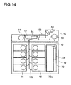
- FIG. 14 A cross-sectional view of the banknote depositing/dispensing machine shown in FIG. 13 is shown in FIG. 14 .
- the banknote depositing/dispensing machine shown in FIG. 14 includes, in the lower unit 1y, not only storing cassettes 16 for storing banknotes but also a collection cassette 70.
- the collection cassette 70 can be removed from the lower unit 1y and is provided with a collection box 70a for collecting overflowing banknotes and a counterfeit banknote collection box 70b for collecting banknotes determined to be counterfeit,
- the storing cassettes 16 are formed with cassettes in which banknotes are sandwiched between two tapes and in which they are wound around the circumferential surface of a rotary drum.
- the upper unit 1x is provided with: a feeding portion 51 for feeding a banknote deposited into the banknote inlet 50 out to the transport path 12; an identification unit 52 for identifying the banknote identification information and authenticity of the banknote deposited through the banknote inlet 50; and a dispending portion 53 for dispensing a banknote to the banknote outlet 10.
- the escrow portion 11 is used to temporarily store the banknotes dispensed from the storing cassettes 16 or the banknote deposited through the banknote inlet 50.
- the bait money storing portion 14 is located closer to the dispensing portion 53 than the escrow portion 11.
- banknotes fed out from the storing cassettes 16 are temporarily stored in the escrow portion 11, and are then dispensed through the dispending portion 53 to the banknote outlet 10.
- the bait money is transported from the bait money storing portion 14 to the dispending portion 53, and is dispensed to the banknote outlet 10.
- banknotes that are determined to be authentic by the identification unit 52 are temporarily stored in the escrow portion 11 from the feeding portion 51, and are then distributed to the storing cassettes 16 in the lower unit 1y according to the type of banknote.
- the bait money deposited in the banknote inlet 50 is transported from the feeding portion 51 to the identification unit 52, where the banknote identification information is checked, and is stored in the bait money storing portion 14.
- the banknote identification information is stored in the memory 21, it may be stored in the higher level terminals 2x and 2y so that it is controlled. Alternatively, the banknote identification information may be stored in a place other than the memory 21 and the higher level terminals 2x and 2y so that it is controlled.
- the bait money storing portion 14 a portion where the bait money 40 is placed is formed with the set tray 41, a cassette that is the same as one of the storing cassettes 16a to 16f may be incorporated into the upper unit 1x instead.
- the bait money storing portion 14 is disposed around the rear surface 1b of the upper unit 1x, if there is a space where the bait money storing portion 14 is disposed, the bait money storing portion 14 may be disposed in such a position closer to the escrow portion 11 that the transport period is more reduced and the rate at which transport failure occurs is more reduced.
- the transport path that transports the bait money from the bait money storing portion 14 to the banknote outlets 10a and 10b may differ from the transport path 12 from the storing cassettes 16a to 16f to the banknote outlets 10a and 10b or at least part thereof may overlap the transport path 12.
- the banknote dispensing machine includes the banknote storing portion of the stack method and the banknote depositing/dispensing machine includes the banknote storing portion of the winding method
- the banknote dispensing machine may include the banknote storing portion of the winding method and the banknote depositing/dispensing machine may include the banknote storing portion of the stack method.
- a banknote to be dispensed is temporarily stored in the escrow portion 11 and is then transported and dispensed to the banknote outlets 10a and 10b
- the escrow portion 11 may be omitted such that a banknotes to be dispensed or the bait money is directly transported and dispensed to the banknote outlets 10a and 10b.
- the present invention can be applied to a banknote depositing/dispensing machine for depositing and dispensing banknotes and a coin-counting machine for dispensing banknotes as change.
Landscapes
- Physics & Mathematics (AREA)
- General Physics & Mathematics (AREA)
- Control Of Vending Devices And Auxiliary Devices For Vending Devices (AREA)
- Cash Registers Or Receiving Machines (AREA)
- Controlling Sheets Or Webs (AREA)
Abstract
Description
- The present invention relates to a banknote handling device that stores banknotes internally, and more particularly to a banknotes handling device that stores bait banknotes separately from banknote that are dispensed in a normal manner.
- Money depositing/dispensing handling systems that deposit and dispense banknotes and coins mechanically and automatically are introduced into windows of financial institutions and transportation facilities and into cash desks of supermarkets, convenience stores and the like. In these money depositing/dispensing handling systems, banknote handling devices are used to deposit and dispense banknotes. These banknote handling devices include: for example, a banknote depositing/dispensing machine (see patent document 1) that is placed behind a counter of a financial institution and with which a teller deposits and dispenses cash; and a banknote handling device (see patent document 2) that is connected to a POS (point of sale) register or the like in a supermarket and that automatically dispenses change. In addition to the devices disclosed in these patent documents, there are banknote dispensing machines that only dispense banknotes.
- Among these banknote handling devices, the devices that deposit and dispense banknotes are provided with a banknote storing portion for feeding and storing banknotes. There are various types of methods in which the banknote storing portion stores banknotes. These storing methods include a stack method in which a stack of banknotes is fed or stored and a winding method in which banknotes are sandwiched between two tapes and wound around a rotary drum (see patent document 3).
- In the money depositing/dispensing system incorporating such a banknote handling device that is introduced with it being kept in mind that a robber forcibly enters to require money, a system is employed in which, if money is required like this, the highest priority is given to human life. As one such system in which the highest priority is given to human life, a system is utilized in which banknotes whose serial numbers or the like is previously recorded are prepared as bait banknotes (hereinafter referred to as "bait money") serving as emergency banknotes and in which, if money is required, the bait money is given so that the highest priority is given to human life and a criminal is pursued.
- As a device in which such a bait money system is utilized, a POS (point of sale) resister is proposed that is provided with a clip connected to an alarm switch and that is used with the bait money held by the clip (see patent document 4). In this POS register, when the bait money held by the clip is removed from a dispensing tray, the switch connected to the clip is turned on, and thus an alarm is activated.
- There is also a device in which the bait money system is utilized in the above-described banknote handling device. In this device, bait money is stored in one of banknote storing portions for storing banknotes that are deposited and dispensed, and, in case of the emergency described above, the bait money is dispensed as emergency banknotes. In such a banknote handling device, information such as serial numbers with which banknotes serving as bait money can be identified is previously recorded, and the banknotes for which this information is recorded are stored in a specific banknote storing portion.
- Patent document 1:
JP-A-2004-145600 - Patent document 2:
JP-A-2005-70899 - Patent document 3:
JP-A-2006-260078 - Patent document 4:
U.S. Patent Number 5,440,107 - Disadvantageously, however, when one of banknote storing portions is used to store bait money, the number of banknote storing portions that are normally used for depositing and dispensing money is reduced, with the result that the performance is degraded. Moreover, when this banknote storing portion is arranged far way from an outlet, it takes longer to dispense money, and the occurrence of a transport failure in a path to the outlet may prevent money from being dispensed.
- An object of the present invention is to provide a banknote handling device that can dispense bait money accurately and quickly in case off an emergency.
- To achieve the above object, according to the invention, there is provided a banknote handling device including: a plurality of banknotes storing portions storing a banknote; a banknote dispensing portion collecting and stacking a banknote to be dispensed; an emergency banknote storing portion that stores an emergency banknote to be dispensed in case of an emergency and that is disposed in a position different from that of the banknote storing portions; a transport portion transporting the banknote from the banknote storing portions or the emergency banknote storing portion to the banknote dispensing portion; and a control portion controlling transport of the emergency banknote by the transport portion so that, in case of an emergency, the emergency banknote stored in the emergency banknote storing portion is dispensed to the banknote dispensing portion.
- According to the present invention, an emergency banknote storing portion that stores an emergency banknote to be dispensed in case of an emergency is disposed in a transport path between banknote storing portions and a banknote outlet, and thus a time period necessary to transport the emergency banknote can be reduced than when money is normally dispensed. Moreover, since the path through which the emergency banknote is transported can be decreased in length, it is possible to prevent the occurrence of a failure caused when the emergency banknote is being transported. Even if a failure is detected by a sensor portion when the emergency banknote is transported, irrespective of whether or not the failure occurs, the emergency banknote can be forcibly dispensed, with the result that the emergency banknote can be reliably dispensed in case of an emergency.
-
- [
Fig. 1 ] An external perspective view showing the configuration of a banknote dispensing machine according to an embodiment of the present invention; - [
Fig. 2 ] A schematic cross-sectional view showing the internal configuration of the banknote dispensing machine shown inFIG. 1 ; - [
Fig. 3 ] A block diagram showing the internal configuration of the banknote dispensing machine shown inFIG. 1 ; - [
Fig. 4 ] A cross-sectional view showing the configuration of a bait money storing portion of the banknote dispensing machine shown inFIG. 1 ; - [
Fig. 5 ] A flow chart showing the main flow of the normal dispensing operation of the banknote dispensing machine shown inFIG. 1 ; - [
Fig. 6 ] A flow chart showing an operation of detecting a failure in a transport path when money is normally dispensed by the banknote dispensing machine shown inFIG. 1 ; - [
Fig. 7 ] A flow chart showing an operation of detecting a failure in the transport path when money is normally dispensed by the banknote dispensing machine shown inFIG. 1 ; - [
Fig. 8 ] A diagram showing, when money is normally dispensed by the banknote dispensing machine shown inFIG. 1 , a banknote transport route within its main body; - [
Fig. 9 ] A diagram showing, when money is normally dispensed by the banknote dispensing machine shown inFIG. 1 , a banknote transport route within its upper unit; - [
Fig. 10 ] A flow chart showing how the banknote dispensing machine shown inFIG. 1 dispenses the bait money; - [
Fig. 11 ] A diagram showing, when the bait money is dispensed by the banknote dispensing machine shown inFIG. 1 , a banknote transport route within its main body; - [
Fig. 12 ] A diagram showing, when the bait money is dispensed by the banknote dispensing machine shown inFIG. 1 , a banknote transport route within its upper unit; - [
Fig. 13 ] An external perspective view showing an example of the configuration of a banknote depositing/dispensing machine according to the present invention; and - [
Fig. 14 ] A schematic cross-sectional view showing the internal configuration of the banknote depositing/dispensing machine shown inFIG. 13 . -
- 1
- Banknote dispensing machine
- 2, 2a and 2b
- Higher level terminal
- 1 0a and 10b
- Banknote outlet
- 11
- Escrow portion
- 12, 12a, 12b and 12x
- Transport path
- 13
- Reject portion
- 14
- Bait money storing portion
- 15
- Sensor portion
- 15a
- Double note detection sensor
- 15b to 15e
- Position detection sensor
- 16a to 16f
- Storing cassette
- 17
- Upper unit control portion
- 18
- Lower unit control portion
- 19
- Communication interface
- 19a
- Communication connector
- 20
- Power supply unit
- 21
- Memory
- 22
- Operation portion
- 23
- Display
- An embodiment of the present invention will be described below with reference to the accompanying drawings. A banknote handling device of this embodiment will be described below by way of example, using a banknote dispensing machine. The banknote dispensing machine of this embodiment is arranged at a counter of a financial institution such as a bank, more specifically, between two tellers behind the counter.
- The mechanical configuration of the banknotes dispensing machine of this embodiment will first be described with reference to
FIG. 1 , which is an external perspective view, andFIG. 2 , which is a schematic cross-sectional view. As shown inFIG. 1 ,higher level terminals banknote dispensing machine 1 of this embodiment. Thehigher level terminals banknote dispensing machine 1. There are three ways of using the banknote dispensing machine 1: with only one of thehigher level terminals banknote dispensing machine 1 is used; and, with both of them, thebanknote dispensing machine 1 is used. - The main body of the
banknote dispensing machine 1 is configured such that, when an operation surface operated by the tellers is referred to as afront surface 1a and the opposite surface of thefront surface 1a is referred to as arear surface 1b, the main body is uprightly mounted with a narrow width in a lateral direction, a wide depth in a forward and backward direction and a long height in a vertical direction. In thebanknote dispensing machine 1,banknote outlets banknote outlets higher level terminals - As shown in the cross-sectional view of
FIG. 2 , thebanknote dispensing machine 1 is composed of: anupper unit 1x including a transport path that transports banknotes to thebanknote outlets FIG. 1 ); and alower unit 1y including storing cassettes that store banknotes. Thebanknote outlets upper unit 1x, in the main body side surfaces 1c and 1d, respectively. Specifically, thebanknote outlets escrow portion 11 to be described later. - The
upper unit 1x is provided with: theescrow portion 11 that temporarily stores banknotes that are fed out to thebanknote outlets transport path 12 for transporting banknotes; areject portion 13 for storing banknotes that fails to be transported satisfactorily due to a transport failure such as double feeding; a baitmoney storing portion 14 for storing a stack of a plurality of banknotes serving as bait money that is fed out in case of an emergency; a doublenote detection sensor 15a that detects double feeding in which a stack of two or more banknotes is transported from thelower unit 1y; andposition detection sensors 15b to 15e for checking whether or not banknotes are normally transported. - The
transport path 12 disposed in theupper unit 1x includes: atransport path 12a that transports a banknote transported from thelower unit 1y into theupper unit 1x; atransport path 12b that transports a banknote from the baitmoney storing portion 14 or thetransport path 12a to theescrow portion 11; and atransport path 12c that branches off thetransport path 12b and that transports a banknote to thereject portion 13. Thereject portion 13, theescrow portion 11 and the baitmoney storing portion 14 are disposed from thefront surface 1a to therear surface 1b so as to be positioned in this order. - The double
note detection sensor 15a is disposed around a connection between thetransport path 12a, into which a banknote from thelower unit 1y is transported and atransport path 12x in thelower unit 1y. Theposition detection sensor 15b is disposed on thetransport path 12a; theposition detection sensor 15c is disposed on thetransport path 12b. Theposition detection sensor 15d is disposed on thetransport path 12b and in front of the transport inlet of theescrow portion 11; theposition detection sensor 15e is disposed on thetransport path 12b and in front of the transport outlet of the baitmoney storing portion 14. - The
lower unit 1y is provided with: a plurality of storingcassettes 16a to 16f that store banknotes of different denominations, respectively; thetransport path 12x that transports banknotes stored in the storingcassettes 16a to 16f to theupper unit 1x; acommunication connector 19a for connection and communication with thehigher level terminals power supply unit 20 that converts an alternating-current power from an external power supply into a direct-current power to feed it to portions of theupper unit 1x and thelower unit 1y. - The control block of the
banknote dispensing machine 1 including the above-described mechanical block will now be described with reference to the block diagram ofFIG. 3 . As shown inFIG. 3 , thebanknote dispensing machine 1 of this embodiment is provided with: an upperunit control portion 17 that controls operations of the blocks of theupper unit 1x; a lowerunit control portion 18 that controls operations of the blocks of thelower unit 1y; acommunication interface 19 that includes thecommunication connector 19a and through which to communicate with a higher level terminal 2 (equivalent to thehigher level terminals FIG. 1 ); amemory 21 that stores identification information such as banknote numbers with which banknotes serving as the bait money stored in the baitmoney storing portion 14 are individually identified, information on the denominations of banknotes stored in the storingcassettes 16a to 16f and the like; anoperation portion 22 through which to directly operate thebanknote dispensing machine 1; and adisplay 23 that produces a display showing the current operational state, a detected failure or the like. - The upper
unit control portion 17 controls operations such as for: transporting a banknote by thetransport path 12 within theupper unit 1x; feeding, from theescrow portion 11, banknotes out to thebanknote outlets reject portion 13; feeding out the bait money from the baitmoney storing portion 14; and producing a display on adisplay 23. The upperunit control portion 17 also receives a signal from a sensor portion 15 (including the doublenote detection sensor 15a and theposition detection sensors 15b to 15e inFIG. 2 ) to detect a banknote transport failure. This upperunit control portion 17 controls the lowerunit control portion 18 and communicates with thehigher level terminal 2 through thecommunication interface 19. Moreover, the upperunit control portion 17 receives an input signal generated by the operation of theoperation portion 21 and checks the details of the operation. - The lower
unit control portion 18 controlled by the upperunit control portion 17 controls operations such as for: transporting a banknote by thetransport path 12x within thelower unit 1y; and feeding out banknotes from the storingcassettes 16a to 16f. The lowerunit control portion 18 receives a signal from an unillustrated sensor to detect a transport failure within thelower unit 1y, and transmits a result obtained by detecting this transport failure to the upperunit control portion 17. - Since the control block of the
banknote dispensing machine 1 is configured as described above, the upperunit control portion 17 receives a control signal through thecommunication interface 19 from thehigher level terminal 2 of higher level, and controls operations of the blocks. As a result of theoperation portion 22 being directly operated, the upperunit control portion 17 also receives a control signal corresponding to the operation of theoperation portion 22, and controls operations of the blocks. - Here, when the amount of money to be dispensed is input through the
operation portion 22 or thehigher level terminal 2 and thus an instruction is given to perform a normal dispensing operation, the upperunit control portion 17 performs an operation to determine, according to the amount of money to be dispensed, the number of banknotes of each denomination to be dispensed. Then, the upperunit control portion 17 checks storage information stored in thememory 21 to select, from the storingcassettes 16a to 16f, storing cassettes corresponding to the denominations of the banknotes to be dispensed. Thereafter, the upperunit control portion 17 controls the lowerunit control portion 18 to feed out banknotes to be dispensed from the selected storing cassettes. - In case of an emergency, when an instruction is given through the
operation portion 22 or thehigher level terminal 2 to dispense the bait money, a stack of a plurality of banknotes serving as the bait money stored in the baitmoney storing portion 14 is fed out to thetransport path 12. Then, when this bait money is dispensed, if the upperunit control portion 17 detects a failure based on a signal from the sensor portion 15 (including theposition detection sensors 15b to 15e inFIG. 2 ), it stores the details of the failure in thememory 21. These operations will be described in detail later. - The configuration of the bait
money storing portion 14 disposed in theupper unit 1x will now be described with reference to the schematic diagram ofFIG. 4 that shows the configuration. As shown inFIG. 4 , the baitmoney storing portion 14 is provided with: a banknote settray 41 where thebait money 40 is placed; a banknote setdetection lever 42 designed such that its curved end protrudes from the surface of theset tray 41 where thebait money 40 is to be placed and comes in contact with thebait money 40 to be placed; a banknoteset detection sensor 43 for detecting, from the displacement of the banknote setdetection lever 42, whether or not thebait money 40 to be placed is present; feedingrollers bait money 40 out to thetransport path 12b; astopper 45 that prevents thebait money 40 from being fed out to thetransport path 12b; and astopper release solenoid 46 that swings thestopper 45 either to prevent thebait money 40 from being transported to thetransport path 12b or to allow thebait money 40 to be transported thereto. - In the bait
money storing portion 14 configured as described above, when thebait money 40 is placed on the surface of theset tray 41 where thebait money 40 is to be placed, the end of the banknote setdetection lever 42, which protrudes from the surface of theset tray 41 where thebait money 40 is to be placed, is pressed by thebait money 40. Thus, the banknote setdetection lever 42 rotates about a position that is far away from the end in contact with thebait money 40 and at which the banknoteset detection sensor 43 is disposed. - The displacement of the banknote set
detection lever 42 resulting from the rotation of the banknote setdetection lever 42 is detected by the banknoteset detection sensor 43, and thus thebait money 40 is found to be placed in theset tray 41. Then, a signal indicating the detection by the banknoteset detection sensor 43 is transmitted to the upperunit control portion 17, with the result that the upperunit control portion 17 finds thebait money 40 to be placed in theset tray 41. - When the
bait money 40 is placed in theset tray 41 as described above, thebait money 40 is sandwiched between the feedingroller 44a fixed to an area below theset tray 41 and the feedingroller 44b that moves vertically so as to remain in contact with the surface of thebait money 40 placed in theset tray 41. Then, thestopper release solenoid 46 holds thestopper 45 in the upper side; the curved end of thestopper 45 protrudes from the surface of theset tray 41 where thebait money 40 is to be placed, and comes in contact with edges of thebait money 40. In this way, thestopper 45 makes contact with thebait money 40, and can thus prevent thebait money 40 from being transported to thetransport path 12b. - When an instruction is given by the upper
unit control portion 17 to transmit thebait money 40, thestopper release solenoid 46 is controlled by the upperunit control portion 17 to move thestopper 45 to the lower side. Specifically, thestopper release solenoid 46 swings thestopper 45 such that the curved end of thestopper 45, which protrudes from the surface of theset tray 41 where thebait money 40 is to be placed, is retracted into the lower side. Thus, the protrusion of thestopper 45 in contact with the edges of thebait money 40 disappears form the area between the settray 41 and thetransport path 12b, and accordingly thebait money 40 enters a state where it can be transported to thetransport path 12b. Then, the upperunit control portion 17 controls thefeeding rollers bait money 40 is transported from the settray 41 to thetransport path 12b. - The normal dispensing operation of the above-described
banknote dispensing machine 1 will be described with reference to the accompanying drawings.FIG. 5 is a flowchart showing the main flow of the normal dispensing operation;FIGS. 6 and7 are flowcharts showing the operation of detecting a failure in thetransport path 12 when money is normally dispensed.FIG. 8 is a diagram showing a banknote transport route within thebanknote dispensing machine 1;FIG. 9 is a diagram showing a banknote transport route in theupper unit 1x. - As shown in PIG. 5, when the amount of money to be dispensed is specified through the
operation portion 22 or thehigher level terminal 2, and an instruction is given to start the normal dispensing operation corresponding to the specified amount of money to be dispensed (step 1), the upperunit control portion 17 first performs an operation to determine, according to the amount of money to be dispensed, denominations required and the number of banknotes of the denominations (step 2). Then, based on the storage information stored in thememory 21, storing cassettes that store the banknotes of the denominations required are found among the storingcassettes 16a to 16f, and a banknote feeding flow for switching the operation of feeding out money from the associated cassette is set by the number of banknotes of each denomination (step 3). - The banknote feeding flow is set and the required number of banknotes of each denomination are fed out from the storing cassette, and the storing cassette is switched to a storing cassette for the subsequent round of feeding. In this way, the normal dispensing operation corresponding to the set feeding flow is started so that the required number of banknotes of each denomination are fed out on a denomination-by-denomination basis (step 4). In this normal dispensing operation, as shown in
FIG. 8 , a banknote is transported from one of the storingcassettes 16a to 16f to thetransport path 12x in thelower unit 1y, and is then transported through thistransport path 12x to thetransport path 12a in theupper unit 1x. - In the
upper unit 1x, whether or not a stack of two or more banknotes is transported to thetransport path 12a is checked by the doublenote detection sensor 15a. Here, if the doublenote detection sensor 15a detects that a stack of two or more banknotes is transported, the upperunit control portion 17 drives thetransport path 12c, which branches off thetransport path 12b, and thetransport path 12c transports, to thereject portion 13, the banknotes transported through thetransport path 12a to thetransport path 12b. In addition to a stack of two or more banknotes detected by the doublenote detection sensor 15a, banknotes such as one that is caught in thetransport path 12 or thetransport path 12x and that is thus folded are transported to thereject portion 13. - If a failure is not detected by the double
note detection sensor 15a, the upperunit control portion 17 drives only thetransport path 12b, and thus the banknote is directly transported by thetransport path 12b to theescrow portion 11. Hence, one banknote after another is fed by thetransport path 12b into theescrow portion 11, and the required number of banknotes of each denomination are stacked and stored according to the order of the denominations set by the feeding flow. Then, each time a signal obtained by detecting, with theposition detection sensor 15d disposed around the transport inlet of theescrow portion 11, the feeding of a banknote into theescrow portion 11 is supplied to the upperunit control portion 17, the number of banknotes fed into theescrow portion 11 is counted. Hence, each time, based on the result of this counting, the required number of banknotes of each denomination are found by the upperunit control portion 17 to be fed in, the lowerunit control portion 18 switches the storing cassettes from which banknotes are fed out. - Here, for example, when the feeding flow is set such that S2 banknotes are dispensed from the storing
cassette 16b and thenS 1 banknotes are dispensed from the storingcassette 16a, the upperunit control portion 17 first supplies the feeding flow to the lowerunit control portion 18. Then, the lowerunit control portion 18 feeds banknotes out from the storingcassette 2b one by one. Here, if the upperunit control portion 17 finds, through the doublenote detection sensor 15a and theposition detection sensors 15b to 15d, that the S2 banknotes are successfully transported to thetransport path 12, the lowerunit control portion 18 then stops the operation of feeding a banknote out from the storingcassette 16b, and banknotes are fed out from the storingcassette 16a one by one. - When such a normal dispending operation is started, as shown in
FIG. 9 , the upperunit control portion 17 detects, from signals from theposition detection sensors 15b to 15d disposed in thetransport paths escrow portion 11 in theupper unit 1x, whether or not a banknote transport failure occurs (step 5). The detection of the banknote transport failure from the signals from theposition detection sensors 15b to 15d will be described with reference to the flowcharts ofFIGS. 6 and7 . - With reference to the flowchart shown in
FIG. 6 , a description will first be given of an operation of detecting, from signals from theposition detection sensors transport paths position detection sensors FIG. 6 , the upperunit control portion 17 checks whether or not, as a result of the denomination of banknotes stored in theescrow portion 11 becoming equal to the amount of money to be dispensed, the dispensing operation is completed (step 501). Here, if the dispensing operation is found to be completed (yes), the operation of detecting a transport failure is completed. - If, in step 501, the dispensing operation is found to continue (no), the upper
unit control portion 17 detects, based on whether or not the signal from theposition detection sensor 15b is present, whether or not a banknote is transported from thetransport path 12x to thetransport path 12a (step 502). Here, if the signal from theposition detection sensor 15b shows that the banknote is transported to the position where theposition detection sensor 15b in thetransport path 12a is disposed (yes), a time period T1 that is measured by an unillustrated timer is set (step 503). - This time period T1 is the upper limit of a time period necessary to successfully transport a banknote from the position of the
position detection sensor 15b in thetransport path 12a to the position of theposition detection sensor 15c in thetransport path 12b. Based on a time period Δt1 during which an operation in steps 504 and 505 to be described later is performed, an integral value N1 determined from T1 / Δt1 may be set in step 503, and the integral value N1 may be decremented by one at a time in step 505 to be described later. In contrast, in step 503, the time period measured by the timer may be initialized to zero and a time period that has elapsed after the initialization may be measured so that the time period is determined to be equal to the predetermined time period T1 in step 506 to be described later. - As described above, if the time period measured by the unillustrated timer is set at the time period T1, based on whether or not the signal from the
position detection sensor 15c is present, whether or not the banknote is transported from thetransport path 12a to thetransport path 12b is detected (step 504). The operation of checking, based on whether or not the signal from theposition detection sensor 15b is present, whether or not the banknotes is transported will be repeated in an operation shown in the flowchart ofFIG. 7 to be described later. - Then, if, in step 504, the signal from the
position detection sensor 15c shows that the banknote is transported to the position where theposition detection sensor 15c in thetransport path 12b is disposed (yes), the process moves to step 501 in order to check whether or not the banknotes is successfully transported to theposition detection sensor 15c in thetransport path 12b. If, in step 502, the signal from theposition detection sensor 15b shows that the banknote is not transported to thetransport path 12a (no), the process also moves to step 501. - If, in step 504, the signal from the
position detection sensor 15c showing that the banknote is transported to the position where theposition detection sensor 15c in thetransport path 12b is disposed is not found (no), the time period measured by the unillustrated timer is reduced only by the time period Δt1 necessary to perform the operation (step 505), and then whether or not a timeout is reached as a result of the reduced time period becoming zero is checked (step 506). Then, if, in step 506, the time period measured by the unillustrated timer is not zero (no), the process moves to step 504, where the signal from theposition detection sensor 15c is checked. If, in step 506, the time period measured by the unillustrated timer becomes zero (yes), the upperunit control portion 17 determines that a banknote transport failure has occurred (step 507), and completes the operation of detecting the transport failure. - Specifically, whether or not the banknote is detected by the
position detection sensor 15c during the time period T1 after the banknote is detected by theposition detection sensor 15b is checked by repeating steps 504 to 506. If the banknote is not detected by theposition detection sensor 15c during the time period T1, a transport failure is determined to occur between the position where theposition detection sensor 15b in thetransport path 12a is disposed and the position where theposition detection sensor 15c in thetransport path 12b is disposed. - With reference to the flowchart of
FIG. 7 , a description will now be given of an operation of detecting, from signals from the position detection sensors I5c and 15d disposed in thetransport path 12b and in front of the transport inlet of theescrow portion 11, a banknote transport failure occurring between theposition detection sensors FIG. 6 , whether or not the dispensing operation is completed is checked as shown in the flowchart ofFIG. 7 (step 511), and, if the dispensing operation is found to be completed, the operation of detecting a transport failure is also completed. - If, in step 511, the dispensing operation is found to continue (no), the upper
unit control portion 17 first detects, based on whether or not the signal from theposition detection sensor 15c is present, whether or not the banknote is transported from thetransport path 12a to thetransport path 12b (step 512). Here, if the banknote is found to be transported to the position where theposition detection sensor 15c in thetransport path 12b is disposed (yes), a time period T2 measured by the unillustrated timer is set (step 513), whereas, if the banknote is found not to be transported to the position where theposition detection sensor 15c in thetransport path 12b is disposed (no), the process moves to step 511. - As with the above-described time period T1, the time period T2 measured by the unillustrated timer may be either incremented or decremented. Time itself may be measured, or, based on a time period Δt2 during which an operation in steps 514 and 515 to be described later is performed, an integral value N2 determined from T2 / Δt2 may be either decremented or incremented, thereby measuring the time period.
- Then, if, in step 513, the time period T2 is set, based on whether or not a signal from the
position detection sensor 15d is present, whether or not the banknote is transported by thetransport path 12b to the transport inlet of theescrow portion 11 is checked (step 514). Here, if the signal from theposition detection sensor 15d shows that the banknote is transported to the transport inlet of the escrow portion 11 (yeas), the process moves to step 511 in order to confirm whether or not the banknote is successfully transported to the transport inlet of theescrow portion 11. In contrast, if whether or not the banknote is transported to the transport inlet of theescrow portion 11 is not found (no), the time period measured by the unillustrated timer is reduced only by the time period Δt2 necessary to perform the operation (step 515), and then whether or not a timeout is reached as a result of the reduced time period becoming zero is checked (step 516). - If, in step 516, the time period measured by the unillustrated timer is not zero (no), the process moves to step 514, where the signal from the
position detection sensor 15d is checked. If, in step 516, the time period measured by the unillustrated timer is zero (yes), the upperunit control portion 17 determines that a banknote transport failure has occurred (step 517), and completes the operation of detecting the transport failure. - Specifically, whether or not the banknote is detected by the
position detection sensor 15d during the time period T2 after the banknote is detected by theposition detection sensor 15c is checked by repeating steps 514 to 516. If the banknote is not detected by theposition detection sensor 15d during the time period T2, a transport failure is determined to occur between the position where theposition detection sensor 15c in thetransport path 12b is disposed and the position where theposition detection sensor 15d in front of the transport inlet of theescrow portion 11 is disposed. - As described above, in step 5, the operation is performed according to the flowcharts of
FIGS. 6 and7 , and thus theposition detection sensors 15b to 15d check whether or not a transport failure occurs in the transport paths including thetransport paths transport path 12x in the lower unit to theescrow portion 11. Then, if a transport failure is found (yes), the dispending operation is stopped (step 6), and thedisplay 23 produces a display showing that the transport failure occurs in the transport path (step 7), and then the operation is completed. The transport failure display may be produced on thehigher level terminals - In this transport failure display, if the transport failure is detected according to the flowchart of FUG. 6, a display showing that the failure occurs between the positions where the
position detection sensors FIG. 7 , a display showing that the failure occurs between the positions where theposition detection sensors - If, in step 5, a failure is not detected in the transport path 12 (no), whether or not the dispensing operation is completed is checked according to whether or not all the banknotes corresponding to the specified amount of money are transported to the escrow portion 11 (step 8). If the dispensing operation is not found to be completed (no), the process moves to step 5, where whether or not a transport failure occurs is checked again, whereas, if the dispensing operation is found to be completed (yes), the transport operation by the
transport path 12 and the operation by thelower unit 1y are stopped (step 9). - When the transport of a banknote by the
transport path 12 and thelower unit 1y is stopped, the banknotes stored in theescrow portion 11 are fed out to either of thebanknote outlets banknote outlets higher level terminals banknote outlets operation portion 22 . - In the normal dispensing operation, when a banknotes transported on the
transport paths transport path 12c is driven to transport the banknotes to thereject portion 13. Likewise, when the inclination of a banknote transported on thetransport paths transport path 12c is driven to transport the banknote to thereject portion 13. When the lowerunit control portion 18 finds a transport failure in thetransport path 12x, the upperunit control portion 17 is notified of the occurrence of the transport failure, then the transport failure is detected in step 5 and the process moves to step 6, where the transport operation is stopped. Although, in the above description, the denomination and the number of banknotes are set based on the input amount of money to be dispensed and then the banknotes are dispensed, banknotes may be dispensed as a result of the denomination and the number of the banknotes being specified through thehigher level terminals operation portion 22. - With reference to the accompanying drawings, a description will be given below of the case where the
banknote dispensing machine 1, which performs the normal dispensing operation as described above, dispenses the bait money stored in the baitmoney storing portion 14 in case of an emergency. PIG. 10 is a flowchart showing an operation of dispensing the bait money;FIG. 11 is a diagram showing a banknote transport route within thebanknote dispensing machine 1; andFIG. 12 is a diagram showing a banknote transport route in theupper unit 1x. - As shown in
FIG. 10 , when an instruction is given through theoperation portion 22 or thehigher level terminal 2 to start the operation of dispensing the bait money (step 101), the upperunit control portion 17 sets a time period T3 that is measured by the unillustrated timer (step 102). This time period T3 is the upper limit of a time period necessary to successfully transport a banknote from the transport outlet of the baitmoney storing portion 14 to the transport inlet of theescrow portion 11. - The time period may be measured by the following procedure: based on a time period Δt3 during which an operation in steps 103, 106, 107 and 110 to 112, etc. to be described later is performed, an integral value N3 determined from T3 / Δt3 is set in step 102, and this integral value N3 is decremented by one at a time, thereby measuring the time period. In contrast, in step 102, the time period measured by the timer may be initialized to zero and a time period that has elapsed after the initialization of the timer may be measured so that the time period is determined to be equal to the predetermined time period T3.
- When the time period is set by the unillustrated timer, the upper
unit control portion 17 controls the operations of the baitmoney storing portion 14 and thetransport path 12b to start the operation of dispensing the bait money (step 103). Specifically, thestopper release solenoid 46 releases the state in which thebait money 40 is prevented by thestopper 45 from being transported, then thefeeding rollers bait money 40 is fed out and simultaneously the transport operation by thetransport path 12b is started. - Then, the upper
unit control portion 17 checks, based on a signal from theposition detection sensor 15e, whether or not a stack of banknotes serving as the bait money passes through the position where theposition detection sensor 15e is disposed, that is, the transport outlet of the bait money storing portion 14 (step 104). Specifically, theposition detection sensor 15e checks whether or not the banknotes serving as the bait money are present in the position where theposition detection sensor 15e in thetransport path 12b is disposed and then disappear from the position where theposition detection sensor 15e in thetransport path 12b is disposed. In this way, the banknotes serving as the bait money are found to be transported from the baitmoney storing portion 14 to thetransport path 12b. - If, in step 104, the stack of banknotes serving as the bait money is not found to pass through (no), the time period measured by the unillustrated timer is reduced only by the time period Δt3 necessary to perform the operation (step 105), and then whether or not a timeout is reached as a result of the reduced time period becoming zero is checked (step 106). Then, if, in step 106, the time period measured by the unillustrated timer is not zero (no), the process moves to step 104, where the signal from the
position detection sensor 15e is checked. In operations in steps 104 to 106, theposition detection sensor 15e checks whether or not the bait money is fed out from the baitmoney storing portion 14, where the bait money is originally stored. - If, in step 106, the time period measured by the unillustrated timer becomes zero (yes), the upper
unit control portion 17 determines that a banknote transport failure has occurred, and stores information on the transport failure in the memory 21 (step 116). Here, thememory 21 stores the information that the transport failure has occurred in the position where theposition detection sensor 15e is disposed, that is, the transport outlet of the baitmoney storing portion 14. - If, in step 104, based on the signal from the
position detection sensor 15e, the stack of banknotes serving as the bait money is found to pass through (yes), even after the stack of banknotes serving as the bait money passes through the position where theposition detection sensor 15e is disposed, whether or not a banknote is detected by theposition detection sensor 15e is checked (step 107). Here, if a banknote is detected by theposition detection sensor 15e (yes), it is determined that not all the bait money passes through, and the process moves back to step 104, where whether or not the bait money passes through is checked by theposition detection sensor 15e. On the other hand, if a banknote is not detected by theposition detection sensor 15e (no), based on the signal from theposition detection sensor 15c disposed on thetransport path 12b, whether or not the stack of banknotes serving as the bait money pass through the position where theposition detection sensor 15c in thetransport path 12b is disposed is checked (step 108). - If, in step 108, the stack of banknotes serving as the bait money is not found to pass through (no), as in steps 105 and 106, the time period measured by the unillustrated timer is reduced only by the time period Δt3 necessary to perform the operation (step 109), and then whether or not a timeout is reached as a result of the reduced time period becoming zero is checked (step 110). In the operation in steps 107 to 110, whether or not the bait money passes through the
transport path 12b in motion is checked by theposition detection sensor 15c, and whether or not a banknote failing to be transported is left is also checked by theposition detection sensor 15e. - Then, if, in step 110, the time period measured by the unillustrated timer is not zero (no), the process moves to step 107, where the signal from the
position detection sensor 15e is checked. On the other hand, if, in step 110, the time period measured by the unillustrated timer becomes zero (yes), the process moves to step 116, where information on the occurrence of a transport failure in the position where theposition detection sensor 15c in thetransport path 12b is disposed is stored in thememory 21. - If, in step 108, based on the signal from the
position detection sensor 15c, the stack of banknotes serving as the bait money is found to pass through (yes), as in step 107, whether or not a banknote is detected by theposition detection sensor 15e, which has found that the stack of banknotes serving as the bait money had passed through, is checked (step 111). Then, if a banknote is detected by theposition detection sensor 15e (yes), the process moves to step 104, where whether or not the bait money passes through is checked by theposition detection sensor 15e. On the other hand, if a banknote is not detected by theposition detection sensor 15e (no), then whether or not a banknote is detected by theposition detection sensor 15c, which has found that the stack of banknotes serving as the bait money had passed through, is checked (step 112). - Then, if, in step 112, a banknote is detected by the
position detection sensor 15c (yes), the process moves to step 107, where whether or not the bait money is present is checked by theposition detection sensor 15e. On the other hand, if a banknotes is not detected by theposition detection sensor 15c (no), based on the signal from theposition detection sensor 15d, whether or not the stack of banknotes serving as the bait money passes through the position where theposition detection sensor 15d at the transport inlet of theescrow portion 11 is disposed is checked (step 113). - If, in step 113, the stack of banknotes serving as the bait money is not found to pass through (no), as in steps 105, 106, 109 and 110, the time period measured by the unillustrated timer is reduced only by the time period Δt3 necessary to perform the operation (step 114), and then whether or not a timeout is reached as a result of the reduced time period becoming zero is checked (step 115). In the operation in steps 111 to 115, whether or not the bait money is fed into the
escrow portion 11, into which the bait money is to be fed, is checked by theposition detection sensor 15d, and whether or not a banknote failing to be transported is left is checked by theposition detection sensors - Then, if, in step 115, the time period measured by the unillustrated timer is not zero (no), the process moves to step 111, where the signal from the
position detection sensor 15e is checked. If, in step 115, the time period measured by the unillustrated timer becomes zero (yes), the process moves to step 116, where information on the occurrence of a transport failure at the transport inlet of theescrow portion 11 is stored in thememory 21. - If, in step 113, based on the signal from the
position detection sensor 15d, the stack of banknotes serving as the bait money is found to pass through (yes), or, in step 116, information on transport failures occurring in the positions where theposition detection sensors 15c to 15e are disposed is stored in thememory 21, the operation of dispensing the bait money is stopped (step 117). Specifically, in the baitmoney storing portion 14, thestopper release solenoid 46 moves thestopper 45 to prevent thebait money 40 from being transported and stops the feeding operation by the feedingrollers transport path 12b is stopped. - Thereafter, the stack of banknotes serving as the bait money stored in the
escrow portion 11 is fed out to the either of thebanknote outlets banknote outlets higher level terminals banknote outlets operation portion 22. Alternatively, it is possible to previously determine which one of thebanknote outlets - Then, if, in step 119, the contents of the
memory 21 show that a transport failure occurs (yes), thedisplay 23 produces a display showing that a transport failure occurs in the transport path (step 120), and the operation is completed. On the other hand, if no transport failure is found (no), the bait money is considered to be normally transported, and the operation is completed. - The display that shows the transport failure in step 120 may be produced on the
higher level terminals position detection sensors - As described above, in the operation of dispensing the bait money, irrespective of whether or not a failure occurs while the bait money is transported, when a predetermined time period elapses or when the bait money is successfully transported, the bait money stored in the
escrow portion 11 is forcibly dispensed to the either of thebanknotes outlets - Even if a failure, other than the transport failure occurring in the
transport path 12b, that occurs due to the length, thickness, inclination or the like of a transported banknote is detected, irrespective of the failure detected, the bait money stored in theescrow portion 11 is forcibly dispensed to the either of thebanknote outlets - In this embodiment, even if a transport failure or the like occurs when the bait money is transported, the bait money is transported to the
escrow portion 11 as continuously as possible and is then dispensed to thebanknote outlets 10a and 14b. Information on various types of detected failures including the transport failure is reliably stored, as failure information, in thememory 21. - A description will be given of a first example of storage of banknotes serving as the
bait money 40 in the baitmoney storing portion 14. When an instruction is given through theoperation portion 22 or the higher level terminals 2x and 2y to store the bait money, a door (not shown) is opened that is provided in the position where the baitmoney storing portion 14 in theupper unit 1x is disposed. A stack of banknotes serving as thebait money 40 is inserted through an insertion port formed by the opening of the door, and is placed in theset tray 41. - Then, when the insertion of the
bait money 40 is found by the banknoteset detection sensor 43 as a result of the banknote setdetection lever 42 being rotated, it is required to input information (hereinafter, "banknote identification information") for identification of banknotes, such as serial numbers for the individual banknotes serving as thebait money 40. Here, a display for requesting the input of the banknote identification information is produced on thedisplay 23 or the higher level terminals 2x and 2y. - When, in response to this input request, the banknote identification information for the individual banknotes serving as the
bait money 40 is input through theoperation portion 22 or the higher level terminals 2x and 2y, the upperunit control portion 17 finds the banknote identification information input. Here, the found banknotes identification information may be displayed on thedisplay 23 or the higher level terminals 2x and 2y. Then, when the banknote identification information for the individual banknotes serving as thebait money 40 placed in the baitmoney storing portion 14 is stored in thememory 21 by the upperunit control portion 17, the door (not shown) provided in the position where the baitmoney storing portion 14 is disposed is closed, and the storage of the bait money is completed. - A description will be given of a second example of storage of banknotes, serving as the
bait money 40 in the baitmoney storing portion 14. This example differs from the first example in that banknotes stored in the storingcassettes 16a to 16f are transported as thebait money 40 to the baitmoney storing portion 14 and are stored therein. Here, when an instruction is given through theoperation portion 22 or the higher level terminals 2x and 2y to store the bait money, the upperunit control portion 17 controls, through the lowerunit control portion 18, the operation of feeding out banknotes by one of the storingcassettes 16a to 16f. - The banknotes that are fed out one by one from the selected one of the storing
cassettes 16a to 16f are transported through thetransport path 12x to theupper unit 1x, and are transported, through thetransport path 12 in theupper unit 1x, to the baitmoney storing portion 14. In this example, there is provided, as thetransport path 12 in theupper unit 1x, a transport path that transports the banknotes from thetransport path 12x in thelower unit 1y to the baitmoney storing portion 14. On the transport path to the baitmoney storing portion 14, in order to find the banknote identification information for the banknotes transported from one of the storingcassettes 16a to 16f to the baitmoney storing portion 14, an unillustrated banknote identification portion for reading the banknote identification information is provided. - When an instruction is given to store the bait money, in the bait
money storing portion 14, thestopper release solenoid 46 releases the state in which a banknote is prevented by thestopper 45 from being transported, with the result that a banknote can be transported through thetransport path 12 to theset tray 41. Then, banknotes, transported through thetransport path 12 to the transport inlet of the baitmoney storing portion 14 are transported, by the rotation of thefeeding rollers money storing portion 14 and are placed in theset tray 41. - When, as described above, banknotes transported as the
bait money 40 are placed in theset tray 41 and stored in the baitmoney storing portion 14, the transport operation by thetransport paths feeding rollers stopper 45 is driven by thestopper release solenoid 46 to prevent a banknote from being transported into or out from the baitmoney storing portion 14. When banknotes transported from one of the storingcassettes 16a to 16f to the baitmoney storing portion 14 are stored as thebait money 40 in the baitmoney storing portion 14, the above-described banknote identification portion reads the banknote identification information for the individual banknotes. This banknote identification information for the banknotes serving as the bait money is found by the upperunit control portion 17 and is then stored in thememory 21. - In a case where, as in this example, the banknote identification portion for reading the banknote identification information is provided, in a device such as a banknote depositing/dispensing machine that is shown in
FIG. 13 and that is provided with abanknote inlet 50, banknote to be stored as thebait money 40 may be deposited through thebanknote inlet 50. Here, thebanknote inlet 50 is disposed in theupper unit 1x, and banknotes inserted into thisbanknote inlet 50 are fed out one by one and transported through thetransport path 12 to the baitmoney storing portion 14, When the banknotes is transported from the inlet to the baitmoney storing portion 14, the banknote identification portion reads the banknote identification information for the individual banknotes, and the banknote identification information is stored in thememory 21. In the banknote depositing/dispensing machine, which is shown inFIG. 13 by way of example, banknotes to be dispensed or the bait money is transported to abanknote outlet 10 disposed below thebanknote inlet 50 and is then dispensed. - A cross-sectional view of the banknote depositing/dispensing machine shown in
FIG. 13 is shown inFIG. 14 . The banknote depositing/dispensing machine shown inFIG. 14 includes, in thelower unit 1y, not only storingcassettes 16 for storing banknotes but also acollection cassette 70. Thecollection cassette 70 can be removed from thelower unit 1y and is provided with acollection box 70a for collecting overflowing banknotes and a counterfeitbanknote collection box 70b for collecting banknotes determined to be counterfeit, In the banknote depositing/dispensing machine shown inFIGS. 13 and14 , the storingcassettes 16 are formed with cassettes in which banknotes are sandwiched between two tapes and in which they are wound around the circumferential surface of a rotary drum. - In addition to the
escrow portion 11 and the baitmoney storing portion 14, theupper unit 1x is provided with: a feedingportion 51 for feeding a banknote deposited into thebanknote inlet 50 out to thetransport path 12; anidentification unit 52 for identifying the banknote identification information and authenticity of the banknote deposited through thebanknote inlet 50; and adispending portion 53 for dispensing a banknote to thebanknote outlet 10. Theescrow portion 11 is used to temporarily store the banknotes dispensed from the storingcassettes 16 or the banknote deposited through thebanknote inlet 50. Here, the baitmoney storing portion 14 is located closer to the dispensingportion 53 than theescrow portion 11. - In this configuration, when money is normally dispensed, banknotes fed out from the storing
cassettes 16 are temporarily stored in theescrow portion 11, and are then dispensed through the dispendingportion 53 to thebanknote outlet 10. When the bait money is dispensed, the bait money is transported from the baitmoney storing portion 14 to thedispending portion 53, and is dispensed to thebanknote outlet 10. When money is normally deposited, among banknotes deposited into thebanknote inlet 50, banknotes that are determined to be authentic by theidentification unit 52 are temporarily stored in theescrow portion 11 from the feedingportion 51, and are then distributed to the storingcassettes 16 in thelower unit 1y according to the type of banknote. When the bait money is deposited, the bait money deposited in thebanknote inlet 50 is transported from the feedingportion 51 to theidentification unit 52, where the banknote identification information is checked, and is stored in the baitmoney storing portion 14. - Although, in the above-described examples of the operation of storing the bait money, the banknote identification information is stored in the
memory 21, it may be stored in the higher level terminals 2x and 2y so that it is controlled. Alternatively, the banknote identification information may be stored in a place other than thememory 21 and the higher level terminals 2x and 2y so that it is controlled. - Although, in the bait
money storing portion 14, a portion where thebait money 40 is placed is formed with theset tray 41, a cassette that is the same as one of the storingcassettes 16a to 16f may be incorporated into theupper unit 1x instead. Although the baitmoney storing portion 14 is disposed around therear surface 1b of theupper unit 1x, if there is a space where the baitmoney storing portion 14 is disposed, the baitmoney storing portion 14 may be disposed in such a position closer to theescrow portion 11 that the transport period is more reduced and the rate at which transport failure occurs is more reduced. - As long as the transport distance between the bait
money storing portion 14 and thebanknote outlets cassettes 16a to 16f and thebanknote outlets money storing portion 14 to thebanknote outlets transport path 12 from the storingcassettes 16a to 16f to thebanknote outlets transport path 12. - Although, in the above-described embodiment, the banknote dispensing machine includes the banknote storing portion of the stack method and the banknote depositing/dispensing machine includes the banknote storing portion of the winding method, the banknote dispensing machine may include the banknote storing portion of the winding method and the banknote depositing/dispensing machine may include the banknote storing portion of the stack method. Although, in the above-described embodiment, a banknote to be dispensed is temporarily stored in the
escrow portion 11 and is then transported and dispensed to thebanknote outlets escrow portion 11 may be omitted such that a banknotes to be dispensed or the bait money is directly transported and dispensed to thebanknote outlets - Although the above-described embodiment is discussed by way of example, using the banknote dispensing machine that is employed by a teller of a financial institution, the present invention can be applied to a banknote depositing/dispensing machine for depositing and dispensing banknotes and a coin-counting machine for dispensing banknotes as change.
Claims (14)
- A banknote handling device comprising:a plurality of banknotes storing portions storing a banknote;a banknote dispensing portion stacking a banknote to be dispensed;an emergency banknote storing portion that stores an emergency banknote to be dispensed in case of an emergency and that is disposed in a position different from a position of the banknote storing portions;a transport portion transporting the banknote from the banknote storing portions or the emergency banknote storing portion to the banknote dispensing portion; anda control portion controlling transport of the emergency banknote by the transport portion so that, in case of an emergency, the emergency banknote stored in the emergency banknote storing portion is dispensed to the banknote dispensing portion.
- The banknote handling device of claim 1, further comprising:a sensor portion that is provided in the transport portion and that detects a state of the banknote being transported in the transport portion; anda transport state determination portion determining, based on an output from the sensor portion, whether or not a banknote transport failure occurs in the transport portion,wherein, when the emergency banknote is transported from the emergency banknote storing portion to the banknote dispensing portion in case of an emergency, irrespective of a result of the determination of the transport state determination portion, the control potion controls the transport by the transport portion such that the emergency banknote is forcibly transported to the banknote dispensing portion.
- The banknote handling device of claim 2, further comprising:a storage portion storing information on the banknote transport failure that occurs in the transport portion and that is determined by the transport state determination portion.
- The banknote handling device of claim 1,
wherein the emergency banknote storing portion is disposed in such a position that a first transport distance over which the emergency banknote is transported from the emergency banknote storing portion to the banknote dispensing portion is shorter than a second transport distance over which the banknote is transported from the banknote storing portions to the banknote dispensing portion. - The banknote handling device of claim 4,
wherein the transport portion is provided with a first transport path transporting the emergency banknote from the emergency banknote storing portion to the banknote dispensing portion and a second transport path transporting the banknote from the banknote storing portions to the banknote dispensing portion, and at least a part of the first transport path overlaps at least a part of the second transport path. - The banknote handling device of claim 1,
wherein a plurality of emergency banknotes stored in the emergency banknote storing portion are dispensed, and the plurality of emergency banknotes are transported in a stack through the transport path to the banknote dispensing portion. - The banknote handling device of claim 1, further comprising:a storage portion storing banknote identification information for identification of the emergency banknote stored in the emergency banknote storing portion.
- The banknote handling device of claim 1,
wherein, when the emergency banknote is dispensed from the banknote dispensing portion in case of an emergency, the emergency banknote stored in the emergency banknote storing portion is dispensed from the banknote dispensing portion within a predetermined period. - The banknote handling device of claim 1,
wherein the banknote dispensing portion comprises:an escrow portion temporarily storing the banknote transported from the transport portion; andan outlet through which the banknote temporarily stored in the escrow portion is dispensed. - The banknote handling device of claim 1, further comprising:a banknote inlet through which a banknote is deposited,wherein the banknote deposited through the banknote inlet is transported through the transport portion to and stored in the banknote storing portions.
- The banknote handling device of claim 10,
wherein, when the emergency banknote is deposited through the banknote inlet, the emergency banknote deposited is transported through the transport portion to and stored in the emergency banknote storing portion. - The banknote handling device of claim 1, further comprising:a first unit including the banknote storing portions; anda second unit including the banknote dispensing portion and the emergency banknote storing portion.
- The banknote handling device of any one of claims 1 to 12, further comprising:an operation input portion through which instructions for operations are given.
- The banknote handling device of any one of claims 1 to 12,
wherein the banknote handing device is connected to a higher level terminal through which instructions for operations are given, the instructions from the higher level terminal are checked by the control portion and thus the operations corresponding to the instructions are performed.
Applications Claiming Priority (1)
| Application Number | Priority Date | Filing Date | Title |
|---|---|---|---|
| PCT/JP2006/325811 WO2008078382A1 (en) | 2006-12-25 | 2006-12-25 | Banknote processing device |
Publications (2)
| Publication Number | Publication Date |
|---|---|
| EP2096606A1 true EP2096606A1 (en) | 2009-09-02 |
| EP2096606A4 EP2096606A4 (en) | 2010-12-29 |
Family
ID=39562181
Family Applications (1)
| Application Number | Title | Priority Date | Filing Date |
|---|---|---|---|
| EP06835181A Withdrawn EP2096606A4 (en) | 2006-12-25 | 2006-12-25 | Banknote processing device |
Country Status (6)
| Country | Link |
|---|---|
| US (1) | US8087581B2 (en) |
| EP (1) | EP2096606A4 (en) |
| JP (1) | JP4927096B2 (en) |
| CN (1) | CN101611426B (en) |
| CA (1) | CA2673763C (en) |
| WO (1) | WO2008078382A1 (en) |
Families Citing this family (11)
| Publication number | Priority date | Publication date | Assignee | Title |
|---|---|---|---|---|
| EP3179454B1 (en) * | 2008-07-28 | 2019-01-02 | Glory Ltd. | Banknote handling system |
| US8019663B1 (en) * | 2008-07-31 | 2011-09-13 | Bank Of America Corporation | Transportation withdrawal and rebalance of cash handling device |
| US8812394B1 (en) * | 2008-11-10 | 2014-08-19 | Bank Of America Corporation | Process and data integration of additional funds into cash handling device and reconciliation |
| JP2012008926A (en) * | 2010-06-28 | 2012-01-12 | Oki Electric Ind Co Ltd | Automatic transaction device |
| JP2012198764A (en) * | 2011-03-22 | 2012-10-18 | Glory Ltd | Money processor |
| JP5786694B2 (en) * | 2011-12-05 | 2015-09-30 | 沖電気工業株式会社 | Banknote handling equipment |
| JP5892908B2 (en) * | 2012-10-17 | 2016-03-23 | 日立オムロンターミナルソリューションズ株式会社 | Automatic cash handling device and cash return method |
| US9792753B2 (en) * | 2013-10-14 | 2017-10-17 | Toshiba International Corporation | Systems and methods for processing bank notes using a distributed tracking system |
| US9373228B2 (en) * | 2014-10-07 | 2016-06-21 | Bank Of America Corporation | Pooled currency delivery system |
| CN105957235A (en) * | 2016-04-25 | 2016-09-21 | 无锡南理工科技发展有限公司 | Currency detector with genuine currency and counterfeit currency dispensing mechanism |
| CN106846612B (en) * | 2016-12-16 | 2023-09-15 | 恒银金融科技股份有限公司 | Financial equipment channel state detection method and device |
Family Cites Families (14)
| Publication number | Priority date | Publication date | Assignee | Title |
|---|---|---|---|---|
| US3432842A (en) * | 1966-01-14 | 1969-03-11 | Robert L Poznanski | Money container with integral holdup alarm |
| GB2045501B (en) * | 1978-12-28 | 1983-05-11 | Laurel Bank Machine Co | Bank note dispensing method and apparatus |
| US5440107A (en) | 1993-10-29 | 1995-08-08 | Texas Instruments Incorporated | Method and apparatus for an improved money drawer assembly with money clip alarm system |
| US7513413B2 (en) * | 1996-11-15 | 2009-04-07 | Diebold, Incorporated | Correlation of suspect currency note received by ATM to the note depositor |
| JP2003141609A (en) * | 2001-11-01 | 2003-05-16 | Fujitsu Ltd | Store deposit / withdrawal device, store deposit / withdrawal system, and store deposit / withdrawal management method |
| US6679422B2 (en) * | 2002-01-31 | 2004-01-20 | International Business Machines Corporation | Automatic teller system and method of marking illegally obtained cash |
| US6550671B1 (en) | 2002-01-31 | 2003-04-22 | International Business Machines Corporation | Cash register and method of accounting for cash transactions |
| JP4559697B2 (en) | 2002-10-24 | 2010-10-13 | グローリー株式会社 | Circulating banknote deposit and withdrawal machine |
| RU2299466C2 (en) | 2002-12-31 | 2007-05-20 | Дайболд, Инкорпорейтед | Banknote cartridge for use with atm |
| JP4166098B2 (en) | 2003-02-06 | 2008-10-15 | 日立オムロンターミナルソリューションズ株式会社 | Banknote handling equipment |
| JP2005070899A (en) | 2003-08-20 | 2005-03-17 | Glory Ltd | Paper money receiving/dispensing device |
| JP4661279B2 (en) | 2004-05-26 | 2011-03-30 | 東洋インキ製造株式会社 | Non-aqueous genuine stain contamination ink |
| JP4704777B2 (en) * | 2004-06-01 | 2011-06-22 | 日立オムロンターミナルソリューションズ株式会社 | Banknote deposit and withdrawal machine |
| JP2006260078A (en) | 2005-03-16 | 2006-09-28 | Glory Ltd | Bill processor |
-
2006
- 2006-12-25 WO PCT/JP2006/325811 patent/WO2008078382A1/en not_active Ceased
- 2006-12-25 JP JP2008550942A patent/JP4927096B2/en not_active Expired - Fee Related
- 2006-12-25 CN CN2006800567824A patent/CN101611426B/en not_active Expired - Fee Related
- 2006-12-25 EP EP06835181A patent/EP2096606A4/en not_active Withdrawn
- 2006-12-25 US US12/520,949 patent/US8087581B2/en not_active Expired - Fee Related
- 2006-12-25 CA CA2673763A patent/CA2673763C/en not_active Expired - Fee Related
Also Published As
| Publication number | Publication date |
|---|---|
| WO2008078382A1 (en) | 2008-07-03 |
| CN101611426B (en) | 2012-01-25 |
| CA2673763C (en) | 2013-05-28 |
| EP2096606A4 (en) | 2010-12-29 |
| JPWO2008078382A1 (en) | 2010-04-15 |
| CA2673763A1 (en) | 2008-07-03 |
| JP4927096B2 (en) | 2012-05-09 |
| US20090319080A1 (en) | 2009-12-24 |
| US8087581B2 (en) | 2012-01-03 |
| CN101611426A (en) | 2009-12-23 |
Similar Documents
| Publication | Publication Date | Title |
|---|---|---|
| JP3849913B2 (en) | Paper sheet handling equipment | |
| US8240450B2 (en) | Apparatus and method for depositing and/or dispensing at least banknotes having a first denomination and banknotes having a second denomination | |
| JP2002190051A (en) | Bill handling equipment | |
| JP5626732B2 (en) | Paper sheet handling equipment | |
| US20090260948A1 (en) | Money handling machine | |
| JP2010272024A (en) | Automatic transaction apparatus | |
| TW201246132A (en) | Paper sheet storage device, and control method and control program for paper sheet storage device | |
| JP2010123091A (en) | Automatic teller machine and method for controlling automatic teller machine | |
| US8087581B2 (en) | Banknote handling device | |
| JP2012198764A (en) | Money processor | |
| KR101527651B1 (en) | Medium processing apparatus | |
| JPH0981829A (en) | Paper money transaction machine and its paying-out method | |
| JP7647370B2 (en) | Media processing device and media transaction device | |
| JPWO1997019426A1 (en) | Paper sheet handling equipment | |
| JP6237911B2 (en) | Medium transport identification apparatus and medium transaction apparatus | |
| JP6303898B2 (en) | Medium discrimination apparatus and medium processing apparatus | |
| JP2003157465A (en) | Bill handling equipment | |
| JP3409211B2 (en) | Cash deposit and withdrawal processing machine | |
| JPH08339466A (en) | Automatic transaction equipment | |
| JP2006184991A (en) | Automatic cash transaction equipment | |
| JPH04205292A (en) | Automatic teller machine | |
| JPH06162324A (en) | Paper money paying and receiving device | |
| JP6781032B2 (en) | Automatic change deposit / withdrawal machine | |
| JP6631088B2 (en) | Cash processing equipment | |
| JPWO2017145482A1 (en) | Paper handling equipment |
Legal Events
| Date | Code | Title | Description |
|---|---|---|---|
| PUAI | Public reference made under article 153(3) epc to a published international application that has entered the european phase |
Free format text: ORIGINAL CODE: 0009012 |
|
| 17P | Request for examination filed |
Effective date: 20090622 |
|
| AK | Designated contracting states |
Kind code of ref document: A1 Designated state(s): AT BE BG CH CY CZ DE DK EE ES FI FR GB GR HU IE IS IT LI LT LU LV MC NL PL PT RO SE SI SK TR |
|
| DAX | Request for extension of the european patent (deleted) | ||
| A4 | Supplementary search report drawn up and despatched |
Effective date: 20101129 |
|
| RIC1 | Information provided on ipc code assigned before grant |
Ipc: G07D 9/00 20060101AFI20080709BHEP Ipc: G07D 11/00 20060101ALI20101123BHEP Ipc: G07F 19/00 20060101ALI20101123BHEP |
|
| STAA | Information on the status of an ep patent application or granted ep patent |
Free format text: STATUS: THE APPLICATION HAS BEEN WITHDRAWN |
|
| 18W | Application withdrawn |
Effective date: 20150224 |