EP2096088A1 - Vieillissement accéléré des fibres optiques dopées au phosphore - Google Patents
Vieillissement accéléré des fibres optiques dopées au phosphore Download PDFInfo
- Publication number
- EP2096088A1 EP2096088A1 EP08021945A EP08021945A EP2096088A1 EP 2096088 A1 EP2096088 A1 EP 2096088A1 EP 08021945 A EP08021945 A EP 08021945A EP 08021945 A EP08021945 A EP 08021945A EP 2096088 A1 EP2096088 A1 EP 2096088A1
- Authority
- EP
- European Patent Office
- Prior art keywords
- fiber
- deuterium
- optical fiber
- hydrogen
- passivation
- Prior art date
- Legal status (The legal status is an assumption and is not a legal conclusion. Google has not performed a legal analysis and makes no representation as to the accuracy of the status listed.)
- Withdrawn
Links
Images


Classifications
-
- C—CHEMISTRY; METALLURGY
- C03—GLASS; MINERAL OR SLAG WOOL
- C03C—CHEMICAL COMPOSITION OF GLASSES, GLAZES OR VITREOUS ENAMELS; SURFACE TREATMENT OF GLASS; SURFACE TREATMENT OF FIBRES OR FILAMENTS MADE FROM GLASS, MINERALS OR SLAGS; JOINING GLASS TO GLASS OR OTHER MATERIALS
- C03C13/00—Fibre or filament compositions
- C03C13/04—Fibre optics, e.g. core and clad fibre compositions
- C03C13/045—Silica-containing oxide glass compositions
- C03C13/047—Silica-containing oxide glass compositions containing deuterium
-
- C—CHEMISTRY; METALLURGY
- C03—GLASS; MINERAL OR SLAG WOOL
- C03C—CHEMICAL COMPOSITION OF GLASSES, GLAZES OR VITREOUS ENAMELS; SURFACE TREATMENT OF GLASS; SURFACE TREATMENT OF FIBRES OR FILAMENTS MADE FROM GLASS, MINERALS OR SLAGS; JOINING GLASS TO GLASS OR OTHER MATERIALS
- C03C25/00—Surface treatment of fibres or filaments made from glass, minerals or slags
- C03C25/60—Surface treatment of fibres or filaments made from glass, minerals or slags by diffusing ions or metals into the surface
- C03C25/607—Surface treatment of fibres or filaments made from glass, minerals or slags by diffusing ions or metals into the surface in the gaseous phase
-
- C—CHEMISTRY; METALLURGY
- C03—GLASS; MINERAL OR SLAG WOOL
- C03C—CHEMICAL COMPOSITION OF GLASSES, GLAZES OR VITREOUS ENAMELS; SURFACE TREATMENT OF GLASS; SURFACE TREATMENT OF FIBRES OR FILAMENTS MADE FROM GLASS, MINERALS OR SLAGS; JOINING GLASS TO GLASS OR OTHER MATERIALS
- C03C25/00—Surface treatment of fibres or filaments made from glass, minerals or slags
- C03C25/62—Surface treatment of fibres or filaments made from glass, minerals or slags by application of electric or wave energy; by particle radiation or ion implantation
- C03C25/626—Particle radiation or ion implantation
- C03C25/6286—Ion implantation
Definitions
- This invention relates to multimode fiber optimized for high capacity transmission around 850nm as well as across wider bandwidths, and optical fiber transmission systems employing that fiber. More specifically it relates to methods for determining conditions for passivation of multiply-doped optical fibers to the effects of hydrogen.
- multi-transverse-mode optical fiber (hereinafter multimode fiber) fiber has an established status for short haul applications, and specialty fibers.
- LAN Local Area Network
- multimode fiber fiber
- Such systems enable low cost by utilizing serial transmission, loose alignment tolerances between source and fiber end, and large alignment tolerances within connections and splices.
- LAN Local Area Network
- the industry has set a standard for minimum acceptable transmission distance, and minimum optical fiber performance for that distance.
- the distance in current use is 300 meters for a single in-building optical link.
- In-building optical links comprise the vast majority of optical links in use today.
- the IEEE draft protocol for 10GBASE-LX4 is a four-channel WDM system operating around 1310nm, that can support up to 300 meters on standard grade multimode fibers.
- This 10GBASE-LX4 solution has met with only modest success in the market due to high optical complexity and tight single mode tolerances, resulting in high cost.
- OM3 fibers per the International Standards Organization (ISO) 11801 designation, are fibers with an effective modal bandwidth (EMB) of 2000 MHz.km at 850 nm.
- EMB effective modal bandwidth
- the integration of VCSEL launch and OM3 fiber provides a low cost 300 meter solution for 10 Gbps LAN, or Gbps Storage Area Network (SAN), transmission, and was standardized by IEEE802.3 in 2002. Typical reach is 1.1km with state of the art OM3 compliant fiber. Since 10GBASE-SR over OM3 fiber is the lowest cost 10 Gb/s 300 meter system, it is the preferred system for new fiber installations.
- IEEE has established the 802.3 10GBASE-LRM (Long Reach Multimode) protocol for 10 Gbps single channel transmission at 1300nm over installed-base Fiber Distributed Data Interface (FDDI) grade, OM2 grade, and OM3 grade, fibers.
- FDDI Fiber Distributed Data Interface
- OM2 grade OM2 grade
- OM3 grade fibers.
- FDDI grade, OM2, and OM3, grade fibers is optimized for 1300nm performance with laser sources.
- the 99% 10GBASE-LRM reach is demonstrated to be only 220m for FDDI grade, but an acceptable 300m for OM3 fiber using electronic dispersion compensation and an offset launch condition.
- the cost of 10GBASE-LRM is expected to be higher than 10GBASE-SR, but lower than 10GBASE-LX4 (the four channel multiplexed system), making it potentially viable in the market place for existing multimode fiber installations.
- a reasonable next-step in higher speed transmission over multimode fiber would be 40 Gbps.
- the two most likely candidates are (what would be called) 40GBASE-SX4 supporting 300 meters over OM3 fiber, and 40GBASE-LRM supporting 220 meter over FDDI grade, OM2, and OM3 fibers.
- the 40GBASE-SX4 would be a CWDM (Coarse Wavelength Division Multiplexing) solution similar to the unsuccessful 10GBASE-LX4 solution, but with some key advantages: 1) Lower cost 850 nm VCSELs would be used instead of DFB (Distributed FeedBack) lasers, 2) Lower packaging cost would be enabled by multimode tolerances 10 times easier than the singlemode tolerances required for LX-4. 3)
- the use of conventional low cost CMOS integrated circuits is enabled with an SX-4 solution operating at 10 GHz frequencies, vs the more expensive silicon-germanium materials required for the 40 GHz ICs used for serial 40 Gb/s solutions.
- the next speed of Ethernet is not 40 GbE but rather 100GbE, with at least one multimode fiber solution included.
- One solution would be 10 x 10Gb parallel transmission over multimode fiber in ribbons. This solution would be very cost effective up to 100m, but would become more expensive than CWDM solutions beyond 200m.
- multimode fibers are needed that are optimized across broad wavelength ranges, coupled with appropriate laser launch conditions, for wavelengths to at least 300 meters, and data rates at 1, 10, and 100 Gb/s.
- the objective is to design fibers that maintain the present low cost for 1 or 10Gbps at 850nm, while opening up other wavelength bands for CWDM of 10 and 20Gbps transmission.
- the improved multimode optical fibers have cores doped with aluminum and/or phosphorus. In preferred embodiments they are doped with germanium and phosphorus, or germanium and aluminum. Optical fibers with these multiply doped cores are shown to provide the optical transmission qualities necessary to meet new standards for short haul optical fiber links. More details on these multiply doped optical fibers are set forth in United States Application Serial No. 11/511,174 , which is incorporated by reference herein.
- passivation with deuterium often increases the initial attenuation of the fiber and for some fiber types or certain regimes of passivation, the resulting fiber can have significantly higher attenuation at end of life than an untreated fiber. Loss caused by both passivation and hydrogen exposure during life varies greatly depending on glass composition, so commercially important fiber types, like singlemode fiber, erbium doped fiber and multimode fiber, all behave differently. Optimum passivation conditions exist, but because the theory of defect passivation is not well understood, choice of passivation conditions has not been well-founded.
- Modified Chemical Vapor Deposition MCVD
- Plasma enhanced Chemical Vapor Deposition PCVD
- OTD Outside Vapor Deposition
- Deviations in the profile near the core-clad boundary are also common in the OVD process where diffusion of dopants occurs readily in soot bodies during dehydration.
- Overfill bandwidth is of limited use for characterizing fibers for laser launch applications. Values of (Max - Min) centroid delays or mask widths derived from differential mode delay (DMD) measurements are more appropriate. DMD 0-23 micron mask width values ⁇ 0.33 ps/nm are preferred for 10Gbps transmission over 300m with VCSELs wherein the Mode Power Distribution (MPD) is constrained to meet the IEEE 802.3ae 10GBASE-SR standard.
- MPD Mode Power Distribution
- An equivalent objective is a modal bandwidth of > 2 GHz-km under certain laser launch condition.
- a set of weighting functions were developed in TIA/EIA-492AAAC-A which can be applied to high resolution DMD measurements to derive the "calculated Effective Modal Bandwidth" or EMBc.
- the lowest EMBc value of the set of 10 values should be above 2 GHz-km to guarantee that a given fiber will provide 10Gbps capacity over any transmitter meeting the 802.3ae specifications.
- profile dispersion is determined by the composition of dopants.
- profile dispersion has larger variation, with a high slope across the broad wavelengths range (750 ⁇ 1600 nm). With less Ge, and mixing with other dopants such as P or Al, the profile dispersion becomes flatter and gives high bandwidth fiber over the wide wavelength range.
- the inventive multimode fiber designs comprise multiply-doped fibers where, in general, a dopant such as Al or P is used to reduce the concentration of Ge required to achieve the requisite numerical aperture (NA) of the fiber. Fluorine may also be used in the fiber cladding to reduce the required amount of positive index dopant.
- Al and P raise the index of silica, while F depresses the index of silica.
- the dispersion of Ge-doped silica is generally higher than the dispersion of Al or P-doped silica, so that fiber modal dispersion is lower when Al 2 O 3 or P 2 O 5 displaces GeO 2 as the index-raising dopant.
- dopant profiles of positive dopants such as Ge, Al or P oxides will be quasi-parabolic, characterized by the parameter "alpha" ( ⁇ ) where ⁇ is typically approximately 2 (e.g., 2 +/- 0.3).
- Fibers are described in which the dopant is solely comprised of Al, or solely of P, or the dopants are multiple combinations comprising of Ge and Al, or Ge and P, or Ge and Al and P.
- the cladding of the fiber may also comprise F-doped glass, reducing the total amount of index-raising dopant necessary to achieve the target NA. It may be advantageous to mix dopants for one or more of several reasons. For example, mixing the dopants will produce better modal dispersion than with either dopant alone; and scattering or aging losses may be improved in some cases in fibers with mixed dopants.
- Table 1 describes 50 micron fiber design parameters having desirable properties described further below.
- TABLE 1 Fiber sample Alpha Ge(Delta) P(Delta) Al(Delta) F Cladding (Delta) F1 2.04 0.01 0 0 0 F2 2.04 0 0 0.01 0 F3 2.04 0 0 0.008 -0.002 F4 2.04 0.006 0 0.002 -0.002 F5 2.04 0.004 0 0.004 -0.002 F6 2.03 0.0025 0.0075 0 0 F7 2.04 0.0025 0.0075 0 0 F8 2.05 0.0025 0.0075 0 0 F9 2.06 0.0025 0.0075 0 0 0 F10 2.07 0.0025 0.0075 0 0 F11 2.08 0.0025 0.0075 0 0 0
- the modal bandwidth of a multimode fiber depends on the laser launch conditions with which it is used. The lowest cost is achieved when launch requirements allow loose alignment tolerances between the laser and fiber. A +/ ⁇ five micron tolerance for VCSEL launch is highly beneficial for the cost of existing 850nm transmitters at 1 and 10Gbps. VCSEL transmitters at wavelengths other than 850nm should meet similar modal power distributions as those for the 802.3ae. Accordingly, the worst-case EMBc is reached by applying the ten TIA weighting functions as a measure of the bandwidth of the inventive wide band multimode fibers across a range of wavelengths.
- a single mode laser with a launch having similar loose tolerances would be a desirable low cost launch option (at the wavelength at which the fiber is optimized).
- edge-emitting lasers with industrial reliability are not optimized for 850nm, while 10Gbps single mode and directly modulated Fabry-Perot (FP) or DFB lasers coupled to a 1300nm optimized fiber have not been accepted by standards bodies in the past. Nonetheless, future applications of wideband fibers may beneficially use edge-emitting InP lasers in the range around 980 to 1120 nm for low cost transmission.
- FP Fabry-Perot
- the Al-doped fibers described in TABLE I have desirable properties for 10Gbps transmission described by 0-23 micron mask width (TABLE 2 below), worst-case modal bandwidth for VCSEL launch (TABLE 3 below), and 9 micron single mode offset launch modal bandwidths (TABLE 4 below).
- the P-doped fibers described in TABLE I have desirable properties for 10Gbps transmission described by 0-23 micron mask width (TABLE 5 below), worst-case modal bandwidth for VCSEL launch (TABLE 6 below), and 9 micron single mode offset launch modal bandwidths (TABLE 7 below).
- the multiply-doped fibers may have index profiles characterized by multi-alpha parabolic exponents to equalize mode dispersion as a function of launch mode power distribution, and/or with subtle features such as steps, depths, kinks, added to further suppress particular mode groups, and/or longitudinal periodic structures to increase mode mixing effects.
- the size of the fiber may be 62.5um/125um, 50um/125um, or other size. Smaller cores, with less core germanium concentration, may be preferred from the standpoint of lowering loss.
- the multiply-doped fibers have OFL bandwidth of > 1200 MHz.km at 850 nm and 500 MHz-km at 1300 nm.
- Dispersion compensation schemes such as electronic dispersion compensation, optical mode filtering, and spatial segmented detection, can be used in either transmitter or receiver ends to increase transmission bit rate and extend reach.
- fibers with modal bandwidths > 1 GHz-km around 1310nm will be easier to equalize with EDC at low cost, than standard OM3 fibers.
- the multiply-doped glass compositions and optical fiber profiles discussed here are processed by conventional methods to form preforms, and to draw optical fiber.
- optical fibers with the compositions described are passivated by treating the optical fibers in a heated atmosphere of deuterium.
- the treatment conditions determine the effectiveness of the passivation treatment.
- the treatment conditions are essentially: time of treatment, concentration of deuterium, and treatment temperature.
- Hydrogen contamination is essentially a three-stage process.
- hydrogen diffuses into the fiber from the surrounding material or atmosphere.
- this interstitial hydrogen becomes an active form capable of reacting to form defects.
- this transformation to an active form is a reversible process and can be modeled either as a splitting of the hydrogen molecules to form radicals or as an adsorption isotherm, similar to a Langmuir isotherm.
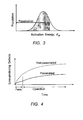
- the active form of hydrogen reacts with existing sites in the glass to form loss-causing defects. Data to date indicates that the reaction occurs with a broad distribution of activation energies. This is illustrated in Fig. 1 , which shows the number density of sites with activation energy, E a .
- Fig. 1 which indicates the population of defects that have reacted with available hydrogen due to exposure at some temperature for some time. As time progresses, more sites are consumed and the growth of the population of reacted sites grows to some asymptotic limit because there is a finite set of glass sites that hydrogen can occupy. The extent of reaction and creation of loss-producing defects grows with time, as illustrated in Fig. 2 .
- Optical fibers such as transmission fiber and erbium-doped fiber can be sufficiently sensitive to reaction with hydrogen at typical operating temperatures and hydrogen levels that the change in optical loss over time is unacceptable.
- passivation procedures have been developed to produce fibers that are more stable over time. Successful passivation reacts the lowest-lying sites and thereby slows the subsequent reaction at operating conditions without inducing unacceptable initial background loss.
- deuterium may be substituted for hydrogen. Since deuterium is chemically similar to hydrogen, the kinetics of reaction with available glass sites is also very similar. However, because of the increase in atomic weight, the absorption spectra associated with deuterium species in glass is radically different than hydrogen.
- the hydroxyl overtone around 1.38 microns in silica which is responsible for most of the optical loss in the telecommunications window around 1.55 microns, is shifted away from the window. This reduces the impact on loss of reaction with deuterium. Thus passivation with deuterium can induce relatively little attenuation of the signal wavelength.
- Figs. 3 and 4 show a population of sites reacted with deuterium during passivation.
- the induced loss is small and can be accounted for prior to placing the optical fiber in service.
- the hydrogen sites remaining (the sites that were not passivated) have higher activation energy than those consumed during passivation, so the reaction rate proceeds more slowly.
- the additional optical loss in service should therefore be small, despite the higher molar absorption of hydrogen. This renders the fiber much more stable over time than a non-passivated fiber.
- Passivation essentially accelerates the consumption of the lowest-lying sites, using accelerated conditions, i.e., much higher temperature and gas pressure than anticipated in service, and fills the sites with species that are relatively loss-less.
- the concepts discussed can be used to allow accurate prediction of the growth of optical loss in a fiber during its service lifetime. Since the reaction with deuterium shifts the optical absorption of the reacted defects away from the wavelength of operation, the loss induced during passivation with deuterium is relatively small. Focus has therefore been on calculating the expected growth of loss during operation, and determining an appropriate level of passivation to attain adequate end-of-life characteristics. Any attenuation due to passivation has been relatively minor and treated as a necessary cost. Since typical passivation conditions may entail temperatures in excess of 100°C for many hours, in some cases the passivation process is limited by coating degradation or simple fiber processing cost, rather than by induced optical loss.
- Fibers exhibit similar excessive loss due to passivation, such as erbium doped fibers intended for exposure to harsh environments or high-reliability applications. These fibers may have high concentrations of aluminum.
- Curve (b) shows more aggressive passivation (at higher temperature, for example), resulting in more incurred passivation loss, but subsequent reactivity has been slowed sufficiently so that after long service time the total incurred loss is lower than in curve (a). Yet more aggressive passivation in curve (c) renders the fiber quite stable to degradation in service, but this does not compensate for the high passivation loss, and the end-of-life loss is higher than curve (b). Thus it is shown that the passivation process can be too severe as well as too mild. While it would normally be assumed that an effective passivation process may only need to account for a passivation threshold, the afore-stated understanding establishes that optimum passivation conditions have both a maximum as well as a minimum. Thus in designing a deuterium passivation process it is desirable to calculate not only the lower limits of process conditions but the upper limits as well.
- One aspect of the invention is an experimental protocol for determining [ H *] t .
- the diffusion constant and solubility of H 2 in silica as a function of temperature and pressure can be obtained from the literature (e.g. Lemaire, Optical engineering, June 1981, V30, no 6, pp 781 equations 2 and 3).
- the hydrogen activity can be determined.
- the dominant activity is adsorption of H 2 directly onto the loss-generating site with subsequent splitting of the hydrogen- hydrogen bond.
- the activity has the form of an adsorption isotherm, with general form 1 + A 1 + A B ⁇ H 2 with [ H 2 ] determined directly from the diffusion and solubility, and A and B estimated experimentally.
- the model above can be fit based on experimental data from appropriate experiments to estimate the activity. Subsequent experiments are helpful in refining the activity to improve the accuracy of long-term prediction.
- a multimode fiber was fabricated with a Ge-P doped core.
- the optical fibers were treated in a heated furnace with an atmosphere of deuterium mixed with nitrogen. Nominal overall pressure was 1 atmosphere.
- simulations were performed to predict fiber end-of-life performance after passivation at 72C and 1 atm of deuterium for different times.
- the exposure durations of 4, 8 and 12 hrs are plotted in the Fig. 6 .
- In service conditions were assumed to be 25C and 10 -4 atm of hydrogen, with an operating lifetime of 10 yrs.
- the short passivation (4hrs) is inadequate for reacting a sufficient population of reactive sites while the long passivation (12hrs) is excessive.
- Minimum end-of-life loss is found at passivation duration of 8 hrs.
- the preferred treatments comprise an initial treatment in heated deuterium, followed by a drive-in anneal in an inert gas, e.g., nitrogen.
- an inert gas e.g., nitrogen.
- the deuterium may be diluted with inert gas to the desired deuterium pressure.
- the inert gas drive-in allows diffusion of absorbed deuterium through the fiber, and allows the desired reactions to occur.
- the pressure of deuterium is preferably 0.25 to 0.75 atmospheres and the preferred overall treatment period is in the range 18 to 30 hours, with a deuterium treatment period of two to six hours.
- the corresponding treatment temperature range is 65 to 100 degrees C.
- Fig. 7 provides raw data measured from unpassivated fiber vs passivated fiber, measured at 1310 nm, at an accelerated condition of 70° C, 0.3 atmosphere H 2 .
- the optical fiber composition was 14% P 2 O 5 , 13% GeO 2 , 73% essentially SiO 2 .
- the horizontal axis is time at the accelerated condition in hours.
- the vertical axis is incremental loss in dB per kilometer.
- the vertical line at approximately 5 hours is a rough estimate of the time at the accelerated condition corresponding to end of life for exposure at 40 C ., 35 years, 0.01 atm hydrogen.
- the estimate of end of life loss for each fiber is given in the legend.
- the effect of passivation can be clearly seen as the unpassivated fiber (triangle symbol ⁇ ) stays strictly above the passivated fibers once the noise floor of the measurement is exceeded.
- compositions of primary interest are silica-based optical fibers co-doped with GeO 2 and P 2 O 5 .
- the mol ratio of GeO 2 to P 2 O 5 may vary widely, for example, from 0.5 to 10.
- the overall dopant concentration typically varies from 15 to 32 mol%, remainder SiO 2 .
- the phosphorus content is generally in the range 2 mol% to 20 mol%.
- Specific compositions of interest are GeO 2 20% +/- 3% with P 2 O 5 3% +/- 1 %, and GeO 2 13% +/- 3% with P 2 O 5 14% +/- 3%.
- Multimode fiber that is the subject of the foregoing description can be recognized as generally having a relatively large core diameter, typically greater than 10 microns. This property distinguishes the optical fiber from single mode optical fiber that typically has a core diameter of 6 microns or less.
Landscapes
- Chemical & Material Sciences (AREA)
- Life Sciences & Earth Sciences (AREA)
- General Chemical & Material Sciences (AREA)
- Engineering & Computer Science (AREA)
- Chemical Kinetics & Catalysis (AREA)
- Geochemistry & Mineralogy (AREA)
- Materials Engineering (AREA)
- Organic Chemistry (AREA)
- General Life Sciences & Earth Sciences (AREA)
- Optics & Photonics (AREA)
- Physics & Mathematics (AREA)
- Health & Medical Sciences (AREA)
- Toxicology (AREA)
- Glass Compositions (AREA)
- Optical Fibers, Optical Fiber Cores, And Optical Fiber Bundles (AREA)
Priority Applications (1)
| Application Number | Priority Date | Filing Date | Title |
|---|---|---|---|
| EP10157306.1A EP2196441B1 (fr) | 2008-02-26 | 2008-12-17 | Vieillissement accéléré des fibres optiques dopées au phosphore |
Applications Claiming Priority (1)
| Application Number | Priority Date | Filing Date | Title |
|---|---|---|---|
| US12/072,433 US8111961B2 (en) | 2008-02-26 | 2008-02-26 | Accelerated aging of phosphorus-doped optical fibers |
Related Child Applications (1)
| Application Number | Title | Priority Date | Filing Date |
|---|---|---|---|
| EP10157306.1A Division EP2196441B1 (fr) | 2008-02-26 | 2008-12-17 | Vieillissement accéléré des fibres optiques dopées au phosphore |
Publications (1)
| Publication Number | Publication Date |
|---|---|
| EP2096088A1 true EP2096088A1 (fr) | 2009-09-02 |
Family
ID=40671002
Family Applications (2)
| Application Number | Title | Priority Date | Filing Date |
|---|---|---|---|
| EP10157306.1A Ceased EP2196441B1 (fr) | 2008-02-26 | 2008-12-17 | Vieillissement accéléré des fibres optiques dopées au phosphore |
| EP08021945A Withdrawn EP2096088A1 (fr) | 2008-02-26 | 2008-12-17 | Vieillissement accéléré des fibres optiques dopées au phosphore |
Family Applications Before (1)
| Application Number | Title | Priority Date | Filing Date |
|---|---|---|---|
| EP10157306.1A Ceased EP2196441B1 (fr) | 2008-02-26 | 2008-12-17 | Vieillissement accéléré des fibres optiques dopées au phosphore |
Country Status (4)
| Country | Link |
|---|---|
| US (1) | US8111961B2 (fr) |
| EP (2) | EP2196441B1 (fr) |
| JP (1) | JP5506210B2 (fr) |
| CN (1) | CN101597144B (fr) |
Cited By (4)
| Publication number | Priority date | Publication date | Assignee | Title |
|---|---|---|---|---|
| WO2013066961A1 (fr) * | 2011-11-04 | 2013-05-10 | Corning Incorporated | Fibre optique multimode co-dopée à ge-p |
| US8498046B2 (en) | 2008-12-04 | 2013-07-30 | Imra America, Inc. | Highly rare-earth-doped optical fibers for fiber lasers and amplifiers |
| US8588568B2 (en) | 2011-11-04 | 2013-11-19 | Corning Incorporated | Bend loss resistant multi-mode fiber |
| US9151889B2 (en) | 2006-09-20 | 2015-10-06 | Imra America, Inc. | Rare earth doped and large effective area optical fibers for fiber lasers and amplifiers |
Families Citing this family (11)
| Publication number | Priority date | Publication date | Assignee | Title |
|---|---|---|---|---|
| US8445059B2 (en) * | 2008-02-26 | 2013-05-21 | Ofs Fitel, Llc | Accelerated aging of phosphorus-doped optical fibers |
| FR2971061B1 (fr) * | 2011-01-31 | 2013-02-08 | Draka Comteq France | Fibre optique a large bande passante et a faibles pertes par courbure |
| JP5797851B2 (ja) * | 2011-11-15 | 2015-10-21 | コーニング インコーポレイテッド | 選択された線引き張力で光ファイバを製造する方法 |
| US8971683B2 (en) * | 2012-10-31 | 2015-03-03 | Corning Incorporated | Multimode optical fiber and systems comprising such fiber |
| WO2018105174A1 (fr) | 2016-12-05 | 2018-06-14 | 古河電気工業株式会社 | Composite de résine de polyéthylène contenant de l'aluminium et de la cellulose dispersés, pastille et corps moulé l'utilisant et procédé pour leur fabrication |
| CN111065679A (zh) | 2017-08-23 | 2020-04-24 | 古河电气工业株式会社 | 分散有纤维素纤维的聚烯烃树脂复合材料、使用了该复合材料的粒料和成型体、以及分散有纤维素纤维的聚烯烃树脂复合材料的制造方法 |
| EP3674048A4 (fr) * | 2017-08-23 | 2021-03-31 | Furukawa Electric Co., Ltd. | Composite de résine de polyéthylène à dispersion de fibres de cellulose, corps moulé et pastilles l'utilisant, procédé de fabrication associé, et procédé de recyclage de fragments de film mince de polyéthylène comprenant des fibres de cellulose collées |
| JP6961703B2 (ja) | 2017-08-23 | 2021-11-05 | 古河電気工業株式会社 | セルロース繊維分散ポリエチレン樹脂複合材、これを用いた成形体及びペレット、これらの製造方法、並びにセルロース繊維付着ポリエチレン薄膜片のリサイクル方法 |
| EP3674360A4 (fr) | 2017-08-23 | 2021-05-12 | Furukawa Electric Co., Ltd. | Composite de résine de polyoléfine contenant des fibres de cellulose dispersées |
| CN108545967A (zh) * | 2018-05-22 | 2018-09-18 | 浙江富春江光电科技有限公司 | 一种光纤氮气智能处理柜 |
| CN108751750A (zh) * | 2018-05-22 | 2018-11-06 | 浙江富春江光电科技有限公司 | 一种衰减稳定超高强度的光纤的制备方法 |
Citations (6)
| Publication number | Priority date | Publication date | Assignee | Title |
|---|---|---|---|---|
| JPS6090852A (ja) * | 1983-10-22 | 1985-05-22 | Furukawa Electric Co Ltd:The | 光ファイバの処理方法 |
| EP0673895A2 (fr) * | 1994-03-24 | 1995-09-27 | AT&T Corp. | Guides d'ondes optiques en verre passivés contre les augmentations de perte induites par l'hydrogène |
| EP1182176A1 (fr) * | 2000-08-25 | 2002-02-27 | Alcatel | Procédé pour la réduction de la sensibilité pour l'hydrogène des fibres optiques |
| US20030084684A1 (en) * | 2001-10-19 | 2003-05-08 | Jds Uniphase Corporation | Method of reducing a hydrogen content of an optical fiber or preform |
| US20070092191A1 (en) * | 2005-11-18 | 2007-04-26 | Koilakh Ahmed M | Optical fiber having reduced hydrogen induced loss and the method for producing the same |
| US20080050075A1 (en) | 2006-08-28 | 2008-02-28 | James William Fleming | Multi-wavelength, multimode optical fibers |
Family Cites Families (9)
| Publication number | Priority date | Publication date | Assignee | Title |
|---|---|---|---|---|
| US4339173A (en) * | 1975-09-08 | 1982-07-13 | Corning Glass Works | Optical waveguide containing P2 O5 and GeO2 |
| JPS60215550A (ja) * | 1984-04-12 | 1985-10-28 | Sumitomo Electric Ind Ltd | 弗素とp↓2o↓5を含有する石英系ガラス光伝送用フアイバ |
| US6499318B1 (en) * | 1994-03-24 | 2002-12-31 | Fitel Usa Corp. | Glass optical waveguides passivated against hydrogen-induced loss increases |
| TW434432B (en) * | 1998-01-19 | 2001-05-16 | Sumitomo Electric Industries | Optical waveguide path grating and method of manufacturing it |
| JP2001255564A (ja) * | 2000-03-09 | 2001-09-21 | Nippon Telegr & Teleph Corp <Ntt> | ラマン増幅用ファイバおよび光ファイバ線路 |
| JP2005112690A (ja) * | 2003-10-10 | 2005-04-28 | Furukawa Electric Co Ltd:The | 光導波路の製造方法 |
| CN1251985C (zh) * | 2004-03-18 | 2006-04-19 | 烽火通信科技股份有限公司 | 一种降低光纤氢损的处理方法以及该方法所使用设备 |
| KR100651528B1 (ko) * | 2004-06-03 | 2006-11-29 | 삼성전자주식회사 | 광섬유의 수소 민감도를 감소하기 위한 방법 |
| US8445059B2 (en) * | 2008-02-26 | 2013-05-21 | Ofs Fitel, Llc | Accelerated aging of phosphorus-doped optical fibers |
-
2008
- 2008-02-26 US US12/072,433 patent/US8111961B2/en active Active
- 2008-12-17 EP EP10157306.1A patent/EP2196441B1/fr not_active Ceased
- 2008-12-17 EP EP08021945A patent/EP2096088A1/fr not_active Withdrawn
-
2009
- 2009-02-10 CN CN2009100058694A patent/CN101597144B/zh not_active Expired - Fee Related
- 2009-02-26 JP JP2009043269A patent/JP5506210B2/ja not_active Expired - Fee Related
Patent Citations (6)
| Publication number | Priority date | Publication date | Assignee | Title |
|---|---|---|---|---|
| JPS6090852A (ja) * | 1983-10-22 | 1985-05-22 | Furukawa Electric Co Ltd:The | 光ファイバの処理方法 |
| EP0673895A2 (fr) * | 1994-03-24 | 1995-09-27 | AT&T Corp. | Guides d'ondes optiques en verre passivés contre les augmentations de perte induites par l'hydrogène |
| EP1182176A1 (fr) * | 2000-08-25 | 2002-02-27 | Alcatel | Procédé pour la réduction de la sensibilité pour l'hydrogène des fibres optiques |
| US20030084684A1 (en) * | 2001-10-19 | 2003-05-08 | Jds Uniphase Corporation | Method of reducing a hydrogen content of an optical fiber or preform |
| US20070092191A1 (en) * | 2005-11-18 | 2007-04-26 | Koilakh Ahmed M | Optical fiber having reduced hydrogen induced loss and the method for producing the same |
| US20080050075A1 (en) | 2006-08-28 | 2008-02-28 | James William Fleming | Multi-wavelength, multimode optical fibers |
Non-Patent Citations (4)
| Title |
|---|
| KAMINOW; PRESBY, AO, vol. 16, no. 1, January 1977 (1977-01-01), pages 108 |
| LEMAIRE, OPTICAL ENGINEERING, vol. 30, no. 6, June 1981 (1981-06-01), pages 781 |
| R. OLSHANSKY, AO, vol. 18, no. 5, January 1979 (1979-01-01), pages 683 |
| SPIE, vol. 3848, pages 260 - 271 |
Cited By (6)
| Publication number | Priority date | Publication date | Assignee | Title |
|---|---|---|---|---|
| US9151889B2 (en) | 2006-09-20 | 2015-10-06 | Imra America, Inc. | Rare earth doped and large effective area optical fibers for fiber lasers and amplifiers |
| US8498046B2 (en) | 2008-12-04 | 2013-07-30 | Imra America, Inc. | Highly rare-earth-doped optical fibers for fiber lasers and amplifiers |
| US8902493B2 (en) | 2008-12-04 | 2014-12-02 | Imra America, Inc. | Highly rare-earth-doped optical fibers for fiber lasers and amplifiers |
| WO2013066961A1 (fr) * | 2011-11-04 | 2013-05-10 | Corning Incorporated | Fibre optique multimode co-dopée à ge-p |
| US8588568B2 (en) | 2011-11-04 | 2013-11-19 | Corning Incorporated | Bend loss resistant multi-mode fiber |
| CN104169760A (zh) * | 2011-11-04 | 2014-11-26 | 康宁股份有限公司 | Ge-P共掺杂的多模光纤 |
Also Published As
| Publication number | Publication date |
|---|---|
| US8111961B2 (en) | 2012-02-07 |
| JP2009203157A (ja) | 2009-09-10 |
| JP5506210B2 (ja) | 2014-05-28 |
| EP2196441A1 (fr) | 2010-06-16 |
| CN101597144A (zh) | 2009-12-09 |
| US20090211303A1 (en) | 2009-08-27 |
| CN101597144B (zh) | 2013-10-30 |
| EP2196441B1 (fr) | 2017-11-15 |
Similar Documents
| Publication | Publication Date | Title |
|---|---|---|
| EP2196441B1 (fr) | Vieillissement accéléré des fibres optiques dopées au phosphore | |
| CN101196593B (zh) | 光纤 | |
| Tamura et al. | The first 0.14-dB/km loss optical fiber and its impact on submarine transmission | |
| US8980369B2 (en) | Accelerated aging of phosphorus-doped optical fibers | |
| EP2418523B1 (fr) | Fibre optique multimodale à indice de gradient diminué | |
| EP2749917B1 (fr) | Matériau en verre de quartz pour former un fibre optique | |
| EP2856225B1 (fr) | Fibre optique multimode et système comprenant une telle fibre | |
| Tsujikawa et al. | Rayleigh scattering reduction method for silica-based optical fiber | |
| EP3715923B1 (fr) | Fibre optique monomode à très faible perte et à grande surface utile et son procédé de fabrication | |
| EP3330755A1 (fr) | Fibre optique à mode unique à très faible atténuation et insensibilité à la courbure | |
| EP3330756B1 (fr) | Fibre optique monomode à grande surface effective et à atténuation ultra-faible | |
| Ten | Ultra low-loss optical fiber technology | |
| Kanamori | Transmission loss of optical fibers; Achievements in half a century | |
| GB2526590A (en) | Optical fiber and method of producing an optical fiber | |
| EP1662280B1 (fr) | Procede de formation d'une ligne de transmission optique, ligne de transmission optique et fibre optique | |
| US6850678B2 (en) | Reduced four-wave mixing optical fiber for wavelength-division multiplexing | |
| US8406599B1 (en) | Reduced brillouin gain coefficient optical fibers and material selection for same | |
| CN111239891A (zh) | 一种低损耗截止波长位移单模光纤 | |
| Sharma et al. | Benefits of Ultra low Loss Fiber in Submarine Transmission | |
| Chang et al. | 2 Optical Fibers to | |
| Ohashi et al. | Optical fiber loss reduction | |
| Kose et al. | Differential mode attenuation in MMFs and its impact on DMD and EMB measurements | |
| Lingle Jr et al. | Single-Mode Fibers | |
| Hirano et al. | Ultra-low loss fiber for 100G-based trans-oceanic transmission |
Legal Events
| Date | Code | Title | Description |
|---|---|---|---|
| PUAI | Public reference made under article 153(3) epc to a published international application that has entered the european phase |
Free format text: ORIGINAL CODE: 0009012 |
|
| AK | Designated contracting states |
Kind code of ref document: A1 Designated state(s): AT BE BG CH CY CZ DE DK EE ES FI FR GB GR HR HU IE IS IT LI LT LU LV MC MT NL NO PL PT RO SE SI SK TR |
|
| AX | Request for extension of the european patent |
Extension state: AL BA MK RS |
|
| 17P | Request for examination filed |
Effective date: 20100302 |
|
| AKX | Designation fees paid |
Designated state(s): FR GB NL |
|
| 17Q | First examination report despatched |
Effective date: 20100511 |
|
| REG | Reference to a national code |
Ref country code: DE Ref legal event code: 8566 |
|
| STAA | Information on the status of an ep patent application or granted ep patent |
Free format text: STATUS: THE APPLICATION IS DEEMED TO BE WITHDRAWN |
|
| 18D | Application deemed to be withdrawn |
Effective date: 20131203 |