EP2095945B1 - Vorrichtung zum Trennen von Laminat - Google Patents
Vorrichtung zum Trennen von Laminat Download PDFInfo
- Publication number
- EP2095945B1 EP2095945B1 EP20090002837 EP09002837A EP2095945B1 EP 2095945 B1 EP2095945 B1 EP 2095945B1 EP 20090002837 EP20090002837 EP 20090002837 EP 09002837 A EP09002837 A EP 09002837A EP 2095945 B1 EP2095945 B1 EP 2095945B1
- Authority
- EP
- European Patent Office
- Prior art keywords
- sheet
- sensors
- edge
- cutting
- laminate
- Prior art date
- Legal status (The legal status is an assumption and is not a legal conclusion. Google has not performed a legal analysis and makes no representation as to the accuracy of the status listed.)
- Not-in-force
Links
- 238000005520 cutting process Methods 0.000 claims description 23
- 238000010030 laminating Methods 0.000 claims description 13
- 238000012937 correction Methods 0.000 claims description 5
- 238000000926 separation method Methods 0.000 description 18
- 238000000034 method Methods 0.000 description 5
- 238000005259 measurement Methods 0.000 description 4
- 239000000853 adhesive Substances 0.000 description 2
- 230000001070 adhesive effect Effects 0.000 description 2
- 238000001514 detection method Methods 0.000 description 2
- 238000003475 lamination Methods 0.000 description 2
- 238000004519 manufacturing process Methods 0.000 description 2
- 239000002985 plastic film Substances 0.000 description 2
- 229920006255 plastic film Polymers 0.000 description 2
- 238000012545 processing Methods 0.000 description 2
- 230000001960 triggered effect Effects 0.000 description 2
- 230000001419 dependent effect Effects 0.000 description 1
- 239000006185 dispersion Substances 0.000 description 1
- 238000011143 downstream manufacturing Methods 0.000 description 1
- 238000003708 edge detection Methods 0.000 description 1
- 239000011888 foil Substances 0.000 description 1
- 239000000463 material Substances 0.000 description 1
- 239000000155 melt Substances 0.000 description 1
- 230000003287 optical effect Effects 0.000 description 1
- 239000004033 plastic Substances 0.000 description 1
- 229920006267 polyester film Polymers 0.000 description 1
- 230000035939 shock Effects 0.000 description 1
- 238000012546 transfer Methods 0.000 description 1
Images

Classifications
-
- B—PERFORMING OPERATIONS; TRANSPORTING
- B32—LAYERED PRODUCTS
- B32B—LAYERED PRODUCTS, i.e. PRODUCTS BUILT-UP OF STRATA OF FLAT OR NON-FLAT, e.g. CELLULAR OR HONEYCOMB, FORM
- B32B38/00—Ancillary operations in connection with laminating processes
- B32B38/0004—Cutting, tearing or severing, e.g. bursting; Cutter details
-
- B—PERFORMING OPERATIONS; TRANSPORTING
- B26—HAND CUTTING TOOLS; CUTTING; SEVERING
- B26D—CUTTING; DETAILS COMMON TO MACHINES FOR PERFORATING, PUNCHING, CUTTING-OUT, STAMPING-OUT OR SEVERING
- B26D1/00—Cutting through work characterised by the nature or movement of the cutting member or particular materials not otherwise provided for; Apparatus or machines therefor; Cutting members therefor
- B26D1/56—Cutting through work characterised by the nature or movement of the cutting member or particular materials not otherwise provided for; Apparatus or machines therefor; Cutting members therefor involving a cutting member which travels with the work otherwise than in the direction of the cut, i.e. flying cutter
- B26D1/62—Cutting through work characterised by the nature or movement of the cutting member or particular materials not otherwise provided for; Apparatus or machines therefor; Cutting members therefor involving a cutting member which travels with the work otherwise than in the direction of the cut, i.e. flying cutter and is rotating about an axis parallel to the line of cut, e.g. mounted on a rotary cylinder
- B26D1/626—Cutting through work characterised by the nature or movement of the cutting member or particular materials not otherwise provided for; Apparatus or machines therefor; Cutting members therefor involving a cutting member which travels with the work otherwise than in the direction of the cut, i.e. flying cutter and is rotating about an axis parallel to the line of cut, e.g. mounted on a rotary cylinder for thin material, e.g. for sheets, strips or the like
-
- B—PERFORMING OPERATIONS; TRANSPORTING
- B26—HAND CUTTING TOOLS; CUTTING; SEVERING
- B26D—CUTTING; DETAILS COMMON TO MACHINES FOR PERFORATING, PUNCHING, CUTTING-OUT, STAMPING-OUT OR SEVERING
- B26D5/00—Arrangements for operating and controlling machines or devices for cutting, cutting-out, stamping-out, punching, perforating, or severing by means other than cutting
- B26D5/20—Arrangements for operating and controlling machines or devices for cutting, cutting-out, stamping-out, punching, perforating, or severing by means other than cutting with interrelated action between the cutting member and work feed
-
- B—PERFORMING OPERATIONS; TRANSPORTING
- B26—HAND CUTTING TOOLS; CUTTING; SEVERING
- B26D—CUTTING; DETAILS COMMON TO MACHINES FOR PERFORATING, PUNCHING, CUTTING-OUT, STAMPING-OUT OR SEVERING
- B26D5/00—Arrangements for operating and controlling machines or devices for cutting, cutting-out, stamping-out, punching, perforating, or severing by means other than cutting
- B26D5/20—Arrangements for operating and controlling machines or devices for cutting, cutting-out, stamping-out, punching, perforating, or severing by means other than cutting with interrelated action between the cutting member and work feed
- B26D5/30—Arrangements for operating and controlling machines or devices for cutting, cutting-out, stamping-out, punching, perforating, or severing by means other than cutting with interrelated action between the cutting member and work feed having the cutting member controlled by scanning a record carrier
- B26D5/32—Arrangements for operating and controlling machines or devices for cutting, cutting-out, stamping-out, punching, perforating, or severing by means other than cutting with interrelated action between the cutting member and work feed having the cutting member controlled by scanning a record carrier with the record carrier formed by the work itself
-
- B—PERFORMING OPERATIONS; TRANSPORTING
- B32—LAYERED PRODUCTS
- B32B—LAYERED PRODUCTS, i.e. PRODUCTS BUILT-UP OF STRATA OF FLAT OR NON-FLAT, e.g. CELLULAR OR HONEYCOMB, FORM
- B32B37/00—Methods or apparatus for laminating, e.g. by curing or by ultrasonic bonding
- B32B37/0046—Methods or apparatus for laminating, e.g. by curing or by ultrasonic bonding characterised by constructional aspects of the apparatus
-
- B—PERFORMING OPERATIONS; TRANSPORTING
- B26—HAND CUTTING TOOLS; CUTTING; SEVERING
- B26D—CUTTING; DETAILS COMMON TO MACHINES FOR PERFORATING, PUNCHING, CUTTING-OUT, STAMPING-OUT OR SEVERING
- B26D5/00—Arrangements for operating and controlling machines or devices for cutting, cutting-out, stamping-out, punching, perforating, or severing by means other than cutting
- B26D5/20—Arrangements for operating and controlling machines or devices for cutting, cutting-out, stamping-out, punching, perforating, or severing by means other than cutting with interrelated action between the cutting member and work feed
- B26D5/22—Arrangements for operating and controlling machines or devices for cutting, cutting-out, stamping-out, punching, perforating, or severing by means other than cutting with interrelated action between the cutting member and work feed having the cutting member and work feed mechanically connected
- B26D5/24—Arrangements for operating and controlling machines or devices for cutting, cutting-out, stamping-out, punching, perforating, or severing by means other than cutting with interrelated action between the cutting member and work feed having the cutting member and work feed mechanically connected including a metering device
-
- B—PERFORMING OPERATIONS; TRANSPORTING
- B32—LAYERED PRODUCTS
- B32B—LAYERED PRODUCTS, i.e. PRODUCTS BUILT-UP OF STRATA OF FLAT OR NON-FLAT, e.g. CELLULAR OR HONEYCOMB, FORM
- B32B2309/00—Parameters for the laminating or treatment process; Apparatus details
- B32B2309/70—Automated, e.g. using a computer or microcomputer
- B32B2309/72—For measuring or regulating, e.g. systems with feedback loops
Definitions
- the invention relates to a device for separating laminate, consisting of a sheet-like film and single sheets, wherein the previously laminated laminate is guided past a cutting station.
- the invention further relates to a device for separating such a laminate.
- a relatively thin and "endless” sheet of plastic material is fed with a sheet to a counter-pressurized pair of laminators and laminated in the nip.
- the adhesion between sheet and film can be brought about by various process variants (eg dispersion, thermal, SF or UV adhesive).
- process variants eg dispersion, thermal, SF or UV adhesive.
- the laminate Before further processing in a downstream process, the laminate must again be singulated into individual sheets, since the sheets are connected to one another by the film.
- EP-B-706 863 a device for separating laminate with a, at the speed of the laminate mitbewegbewegbaren cutting knife, which is designed as a thermal cutting knife whose rotational speed is computer controlled.
- the laminate is fed to the cutting station on a tabletop.
- a flat table top is disclosed which contains recesses for optical sensors. To enable a format-controlled control of the sheet leading edge.
- a feed table according to DE-A-10355459 should allow safe guidance of sheets from the feed table to a transfer cylinder, which is why a tabletop top concentric ge around a frame point of a rotating pregripper leads is and runs slightly below a circle of gripper strips.
- the shows US 2002/0074090 A1 a laminating apparatus and a method of producing laminated articles.
- This device is preferably intended for laminating posters. To ensure that the posters are straight, the device has two sensors that can detect the lateral edges of the poster being loaded.
- the mechanical separation processes are simple, reliable and separate the film along the trailing edge of the sheet.
- the cutting cycle is primarily triggered by sheet leading edge scanning.
- polyester films can not be separated with the mechanical separation methods.
- the laminate web is guided past a rotating hot knife.
- the hot separation knife melts the film along the trailing edge of the sheet, whereby the separation time is triggered by the sheet trailing edges or the sheet leading edge detection.
- the rotating hot knife runs in the separation area at about the same speed as the laminate to be separated.
- the invention has for its object to avoid the disadvantages of the prior art and a device for separating laminate, consisting of a sheet-like film and single sheets, wherein the previously laminated laminate is led past a cutting station to develop.
- Single sheets are fed to a lamination Unterschuppt and the laminate subsequently passes into a cutting station, where the cutting operation preferably by means of a rotating Heis technically feasiblenmessers the applicant takes place.
- the separation position of the individual sheets are recorded before or after laminating.
- the trailing edge of the sheet is measured with a two-position measurement.
- the two-position measurement of the sheet trailing edge is preferably in the left and right edge area of a sheet (one sensor on each side), with two sensor, and it is possible to correct the cutting length and knife axis.
- Inaccuracies in the sheet feeder are thus better detectable, regardless of whether the sheets are skewed, offset or fed with lateral deviations.
- a separation accuracy with respect to the trailing edge of the sheet of less than 0.5 mm is achievable, which significantly increases process reliability. Traffic jams or production stoppages are significantly reduced.
- a laminate 3 consisting of a plastic film 1 and a sheet 2 is supplied in the inlet region in a known manner from a laminating station in shock or underfed continuously to a cutting station 4 with a rotating hot separating knife 5.
- two suitable sensors 6 for detecting the upper, outer sheet trailing edges are arranged in the edge area (9, 9') of a sheet 2 in front of the rotating hot strip meter 5 and vacuum belt transport.
- the sensors 6 are motor-adjustable transversely to the transport direction.
- Line sensors scan the lateral edges of the sheet left and right. With the lateral sheet edge scan, the sensors 6 are positioned laterally to the sheet edge. This ensures that the measuring points 8,8 '(sensors) are arranged in the edge region (9,9').
- the sensors 6 can be moved independently of each other. Corrections are made on the basis of a defined basic value.
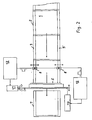
- Fig. 2 Possible position deviations of bends are shown.
- the line sensors are arranged in the region of the sensors 6.
- the sensors 6 are arranged transversely to the transport direction at a distance to the rotating Heisstrennmesser, which is preferably smaller than the minimum processable sheet size (minimum arc length I).
- Hold-down rollers keep the curved path in the area of the measuring point calm.
- the Heisstrennmesser 5 is provided with a motor-driven actuator 10 for axis correction (position correction) and such an actuator 11 for correcting the cutting length (length correction).
- the actuators 10, 11 are each connected via a control unit 12 with the measuring device 8, 8 ', so that deviations of the sheet position for the cutting process can be considered. With the two-point measurement trailing edges are detected, the trailing edge position is detected and it can be an orientation of trailing edges.
- the measured values of the two-position measurement are the basis of an automated knife adjustment.
- a vacuum conveyor belt 13 is arranged for a position-stable sheet transport.
- the separate sheets 2 'reach a conveyor belt with sheet separation 7 for further handling.
- all common films can be separated in all common laminating (adhesive) and it can be achieved deviations from a nominal size of less than 0.5 mm.
Landscapes
- Life Sciences & Earth Sciences (AREA)
- Forests & Forestry (AREA)
- Engineering & Computer Science (AREA)
- Mechanical Engineering (AREA)
- Lining Or Joining Of Plastics Or The Like (AREA)
- Folding Of Thin Sheet-Like Materials, Special Discharging Devices, And Others (AREA)
Description
- Die Erfindung betrifft eine Vorrichtung zum Trennen von Laminat, bestehend aus einer bahnförmigen Folie und Einzelbögen, wobei das vorgängig kaschierte Laminat an einer Schneidstation vorbeigeführt wird. Die Erfindung betrifft weiterhin eine Vorrichtung zum Trennen von solchem Laminat. In diesem Zusammenhang wird auf die
DE 10123521 C1 hingewiesen - Eine relativ dünne und "endlose" Folie aus einem Kunststoffmaterial wird mit einem Bogen einer Laminiereinheit mit gegendruckbeaufschlagtem Walzenpaar zugeführt und im Walzenspalt laminiert. Die Haftung zwischen Bogen und Folie kann durch verschiedene Verfahrensvarianten herbeigeführt werden (z. B. Dispersions-, Thermo-, SF- oder UV Kleber). Üblicherweise werden die einzelnen, aufeinander folgenden Bogen unterlappt den Walzen zugeführt, um das Verkleben der Folie auf der Gegendruckwalze zu verhindern.
- Vor der Weiterverarbeitung in einem nachgeordneten Prozess muss das Laminat wiederum zu einzelnen Bogen vereinzelt werden, da die Bögen durch die Folie miteinander verbunden sind.
- Die Trennung erfolgt zum Beispiel mittels eines rotierenden Messers. So beschreibt die
EP-B-706863 - Das Laminat wird hierbei auf einem Tischblech der Schneidstation zugeführt. In der
DE-A-10028070 ist ein ebenes Tischblech offenbart, das Ausnehmungen für optische Sensoren enthält. Ermöglicht werden soll eine formatgesteuerte Kontrolle der Bogenvorderkante. Ein Anlegetisch gemäss derDE-A-10355459 soll eine sichere Führung von Bögen vom Anlegetisch zu einem Übergabezylinder ermöglichen, weshalb eine Tischblechoberseite konzentrisch um einen Gestellpunkt eines rotierenden Vorgreifers ge führt ist und geringfügig unterhalb eines Flugkreises der Greiferaufschlagleisten verläuft. - Bei einem Verfahren zum Kaschieren und Trennen eines Laminates gemäss
EP-B-1282510 werden Einzelbögen der Kaschierstation zugeführt und das Laminat wird an einer Schneidstation vorbeigeführt. Hierbei werden die Trennstellen noch vor der Kaschierung laufend durch einen Kantensensor an der oberen Hinterkante der Bögen detektiert. Die Schneidfunktion wird auf der Grundlage der detektierten Kantensignale eingeleitet. Eine ähnliche Vorrichtung wird in derWO 01/76832 A1 - Des weiteren zeigt die
US 2002/0074090 A1 eine Vorrichtung zum Laminieren und ein Verfahren zur Herstellung von laminierten Artikeln. Diese Vorrichtung ist bevorzugt zum Laminieren von Postern vorgesehen. Um sicherzustellen, dass die Poster gerade liegen, weist die Vorrichtung zwei Sensoren auf, die die seitlichen Kanten des zulaminierenden Posters detektieren können. - Bekannt ist auch eine Folienkaschiermaschine, bei der Kaschier- und Schneideinheit voneinander getrennt sind und eine Bogenhinterkante nach dem Kaschieren detektiert werden sollte. Eine zuverlässige Hinterkantendektektion konnte jedoch nicht erreicht werden.
- Durch die Anordnung nur eines Sensors und Erfassung nur eines Positionswertes ist eine präzise Bogentrennung nicht in jedem Fall gewährleistet.
- Zum Trennen sind folgende Verfahren bekannt:
-
- 1.1 Querschneider
Ein Trennmesser wird quer/schräg zum Bogenlauf entlang der Bogenhinterkante geführt und durchtrennt dabei die Folie an der Bogenhinterkante. Diese Art der Bogentrennung eignet sich jedoch nicht für hohe Produktionsleistungen. - 1.2 Folie einseitig an der Bogenhinterkante anschneiden oder im Unterlappungsbereich aufreiben (einseitig im Randbereich der Unterlappung) und anschliessend mit einer Reisswalze trennen.
- 1.3 Folie einseitig im Randbereich mittels Perforationsrad perforieren und anschliessend mit einer Reisswalze trennen
- Die mechanischen Trennverfahren sind einfach, zuverlässig und trennen die Folie entlang der Bogenhinterkante. Der Schneid- bzw. Reisszyklus wird vorwiegend mittels Bogenvorderkantenabtastung ausgelöst.
Mit den mechanischen Trennverfahren können u.a. Polyesterfolien nicht getrennt werden. - Die Laminatbahn wird an einem rotierenden Heisstrennmesser vorbeigeführt. Das Heisstrennmesser schmilzt die Folie entlang der Bogenhinterkante, wobei der Trennzeitpunkt über die Bogenhinterkanten oder die Bogenvorderkantendetektion ausgelöst wird. Das rotierende Heisstrennmesser läuft im Trennbereich in etwa mit derselben Geschwindigkeit wie das zu trennende Laminat.
- Die Anordnung nur eines Sensors und Erfassung nur eines Positionswertes setzt eine exakte Bogenausrichtung sowie genau zugeschnittene Bogen voraus. Zudem dürfen sich die Bogen nach dem Ausrichten bis zur Laminierstation in ihrer Lage nicht mehr verändern (Bogentransport). Mit dem thermischen Trennverfahren können alle gängigen Folien getrennt werden.
- Damit die nachfolgende Bogenvereinzelung störungsfrei funktioniert, ist eine exakte Trennung entlang der Bogenhinterkante notwendig. Zudem können überstehende Folien im Bogenstapel Probleme bei der Weiterverarbeitung zur Folge haben.
- Der Erfindung liegt die Aufgabe zugrunde, die Nachteile des Standes der Technik zu meiden und eine Vorrichtung zum Trennen von Laminat, bestehend aus einer bahnförmigen Folie und Einzelbögen, wobei das vorgängig kaschierte Laminat an einer Schneidstation vorbeigeführt wird zu entwickeln.
- Die Aufgabe ist mit den Merkmalen des Patentanspruchs 1 gelöst.
- Einzelbögen werden unterschuppt einer Kaschierstation zugeführt und das Laminat gelangt nachfolgend in eine Schneidstation, wo der Schneidvorgang bevorzugt mittels eines rotierenden Heisstrennmessers der Anmelderin erfolgt. Die Trennposition der einzelnen Bogen werden vor oder nach dem Kaschieren erfasst. Die Erfassung der Bogenhinterkante erfolgt mit einer Zwei-Positionenmessung.
- So erfolgt die Zwei-Positionenmessung der Bogenhinterkante bevorzugt im linken und rechten Randbereich eines Bogens (ein Sensor auf jeder Seite), mit zwei Sensor, und es ist eine Korrektur von Schnittlänge und Messerachse möglich.
- Ungenauigkeiten bei der Bogenzuführung sind somit besser erfassbar, unabhängig davon, ob die Bögen schräg, versetzt oder mit seitlichen Abweichungen zugeführt werden. Erreichbar ist eine Trenngenauigkeit gegenüber der Bogenhinterkante von weniger als 0,5 mm, was die Prozesssicherheit deutlich erhöht. Stau oder Produktionsunterbrechungen werden deutlich reduziert.
- Bevorzugte Ausführungsformen sind im Unteranspruch offenbart.
- Die Erfindung wird nachfolgend in einem Ausführungsbeispiel anhand einer Zeichnung näher beschrieben. In der Zeichnung zeigen die
- Fig. 1:
- eine Schneidstation zum Trennen der Bögen
- Fig. 2:
- die Schneidstation in einer zweiten Ansicht
- In einer nicht explizit dargestellten Laminiermaschine wird im Einlaufbereich ein Laminat 3, bestehend aus einer Kunststofffolie 1 und einem Bogen 2 in bekannter Weise von einer Laminierstation Stoss an Stoss oder unterschuppt kontinuierlich einer Schneidstation 4 mit einem rotierenden Heisstrennmesser 5 zugeführt.
- In Transportrichtung (Pfeilrichtung in
Fig. 1 und2 ) sind vor dem rotierenden Heisstrennmesser 5 und Vakuumbogentransport zwei geeignete Sensoren 6 zur Detektion der oberen, äusseren Bogenhinterkanten (Messeinrichtung 8,8') im Randbereich (9,9') eines Bogens 2 angeordnet. Die Sensoren 6 sind quer zur Transportrichtung motorisch verstellbar. Zeilensensoren tasten die seitlichen Bogenkanten links und rechts ab. Mit der seitlichen Bogenkantenabtastung werden die Sensoren 6 seitlich zur Bogenkante positioniert. Somit ist gewährleistet, dass die Messstellen 8,8' (Sensoren) im Randbereich (9,9') angeordnet sind. - Die Sensoren 6 können unabhängig von einander verfahren werden. Korrekturen erfolgen ausgehend von einem definierten Grundwert.
- In
Fig. 2 sind mögliche Lageabweichungen von Bögen dargestellt. Die Zeilensensoren sind im Bereich der Sensoren 6 angeordnet. - Die Sensoren 6 sind quer zur Transportrichtung in einem Abstand zum rotierenden Heisstrennmesser angeordnet, der bevorzugt kleiner ist als das minimal verarbeitbare Bogenformat (minimale Bogenlänge I).
- Niederhalterollen halten die Bogenbahn im Bereich der Messstelle ruhig.
- Das Heisstrennmesser 5 ist mit einer motorisch betriebenen Stelleinheit 10 zur Achskorrektur (Lagekorrektur) sowie einer solchen Stelleinheit 11 zur Korrektur der Schnittlänge (Längenkorrektur) versehen.
- Die Stelleinheiten 10, 11 sind jeweils über eine Steuereinheit 12 mit der Messeinrichtung 8, 8' verbunden, so dass Abweichungen der Bogenposition für den Schneidvorgang berücksichtigt werden können. Mit der Zweipunktmessung werden Hinterkanten erfasst, die Hinterkantenposition wird erkannt und es kann eine Ausrichtung von Hinterkanten erfolgen.
- Die Messwerte der Zwei-Positionenmessung sind dabei die Basis einer automatisierten Messerverstellung. Unter dem Heisstrennmesser 5 ist ein Vakuum-Transportband 13 für einen lagestabilen Bogentransport angeordnet.
- Die getrennten Bögen 2' gelangen auf ein Transportband mit Bogenvereinzelung 7 zur weiteren Handhabung.
- Somit können alle gängigen Folien bei allen gängigen Laminierverfahren (Kleberarten) getrennt werden und es sind Abweichungen von einem Sollmass von weniger als 0,5 mm erreichbar.
-
- 1
- Kunststofffolie
- 2
- Bogen
- 2'
- Bogen
- 3
- Laminat
- 4
- Schneidstation
- 5
- Heisstrennmesser
- 6
- Sensor
- 7
- TransportbandmitBogenvereinzelung
- 8
- Bogenhinterkantenmesseinrichtung
- 8'
- Bogenhinterkantenmesseinrichtung
- 9
- Randbereich
- 9'
- Randbereich
- 10
- Stelleinheit
- 11
- Stelleinheit
- 12
- Steuereinheit
- 13
- TransportbandTrennstation
- I
- minimaleBogenlänge
Claims (2)
- Vorrichtung zum Trennen von Laminat (3), zumindest umfassend eine Kaschierstation und einer Schneidstation (4), wobei die Vorrichtung vor der Schneidstation (4) Kantensensoren (6) zur Detektion der oberen Hinterkante des Bogens aufweist und die Schneidfunktion auf der Basis detektierter Kantensignale eingeleitet wird,
dadurch gekennzeichnet,
dass die Vorrichtung zwei Sensoren (6) zur Detektion der oberen Hinterkante umfasst, wobei je ein Sensor (6) pro Messkopf auf die Hinterkante im linken bzw. rechten Randbereich des Bogens (2) ausgerichtet ist, wobei die Schneidstation (4) mit einem rotierenden Heisstrennmesser (5) versehen ist, wobei das Heisstrennmesser (5) mit motorischen Stelleinheiten für Achskorrektur und Schnittlänge versehen ist, wobei Sensoren (6) quer zur Transportrichtung motorisch verstellbar angeordnet sind. - Vorrichtung nach Anspruch 1, dadurch gekennzeichnet, dass die Sensoren (6) in Transportrichtung in einem Abstand zum rotierenden Heisstrennmesser (5) angeordnet sind, der kleiner ist als das verarbeitbare Bogenformat Bogenlänge.
Applications Claiming Priority (1)
| Application Number | Priority Date | Filing Date | Title |
|---|---|---|---|
| DE200810011544 DE102008011544A1 (de) | 2008-02-28 | 2008-02-28 | Verfahren zum Trennen von Laminat |
Publications (2)
| Publication Number | Publication Date |
|---|---|
| EP2095945A1 EP2095945A1 (de) | 2009-09-02 |
| EP2095945B1 true EP2095945B1 (de) | 2013-10-09 |
Family
ID=40749216
Family Applications (1)
| Application Number | Title | Priority Date | Filing Date |
|---|---|---|---|
| EP20090002837 Not-in-force EP2095945B1 (de) | 2008-02-28 | 2009-02-27 | Vorrichtung zum Trennen von Laminat |
Country Status (2)
| Country | Link |
|---|---|
| EP (1) | EP2095945B1 (de) |
| DE (1) | DE102008011544A1 (de) |
Families Citing this family (9)
| Publication number | Priority date | Publication date | Assignee | Title |
|---|---|---|---|---|
| DE102009053097A1 (de) | 2009-11-13 | 2011-07-21 | Steinemann Technology Ag | Laminierverfahren und Verfahren und Vorrichtung zum Trennen von Laminat |
| DE102009058334A1 (de) * | 2009-12-15 | 2011-06-16 | Steinemann Technology Ag | Bogen - Laminiermaschine und Verfahren zum Betrieb einer solchen Laminiermaschine |
| CN102294904A (zh) * | 2011-05-13 | 2011-12-28 | 深圳市贤俊龙彩印有限公司 | 一种复膜方法及装置 |
| DE102016221530A1 (de) * | 2016-11-03 | 2018-05-03 | Koenig & Bauer Ag | Laminierungsmaschine und ein Verfahren zum Laminieren von Bogen eines Materials |
| DE102016015774B4 (de) | 2016-11-03 | 2021-07-22 | Koenig & Bauer Ag | Laminierungsmaschine |
| DE102016221528B4 (de) * | 2016-11-03 | 2024-01-11 | Koenig & Bauer Ag | Laminierungsmaschine mit einer Trennvorrichtung zum Abtrennen von Abschnitten von einer Materialbahn |
| DE102016221529A1 (de) | 2016-11-03 | 2018-05-03 | Koenig & Bauer Ag | Laminierungsmaschine |
| DE102016221527A1 (de) | 2016-11-03 | 2018-05-03 | Koenig & Bauer Ag | Laminierungsmaschine mit Einziehmittel und ein Verfahren zum Laminieren eines Materials |
| CN117621151B (zh) * | 2023-11-02 | 2026-04-17 | 风帆有限责任公司 | 一种排气刺刀 |
Family Cites Families (10)
| Publication number | Priority date | Publication date | Assignee | Title |
|---|---|---|---|---|
| US4680079A (en) * | 1984-03-16 | 1987-07-14 | Fujitsu Limited | Printed circuit board laminating apparatus |
| DE59310123D1 (de) | 1992-03-24 | 2001-01-04 | Steinemann Ulrich Ag | Verfahren und Vorrichtung zur Trennung von kaschierten Laminaten |
| WO2001076832A1 (en) * | 2000-04-10 | 2001-10-18 | Europlast Engineering S.A. | Cutting device for sheet laminator |
| WO2001087599A1 (de) | 2000-05-18 | 2001-11-22 | Steinemann Technology Ag | Verfahren und vorrichtung zum trennen eines laminates |
| DE10028070B4 (de) | 2000-06-09 | 2008-11-13 | Koenig & Bauer Aktiengesellschaft | Vorrichtung zur formatabhängigen Lageerfassung der Bogenvorderkante im Anleger von bogenverarbeitenden Maschinen |
| US6521076B1 (en) * | 2000-06-30 | 2003-02-18 | Owens Corning Fiberglas Technology, Inc. | Method of making shingles of two different dimensions using a common shingle mat size |
| JP2002166476A (ja) * | 2000-11-30 | 2002-06-11 | Canon Inc | ラミネート装置及びラミネート成品の製造方法 |
| DE10123521C1 (de) * | 2001-05-15 | 2002-10-02 | Friz Kaschiertechnik Gmbh | Verfahren und Vorrichtung zum Durchlaufkaschieren von plattenförmigen Werkstücken |
| GB2389559B (en) * | 2002-06-10 | 2005-04-06 | Kingspan Res & Dev Ltd | Manufacture of insulating panels |
| DE10355459A1 (de) | 2003-11-27 | 2005-06-23 | Koenig & Bauer Ag | Anlegtisch |
-
2008
- 2008-02-28 DE DE200810011544 patent/DE102008011544A1/de not_active Withdrawn
-
2009
- 2009-02-27 EP EP20090002837 patent/EP2095945B1/de not_active Not-in-force
Also Published As
| Publication number | Publication date |
|---|---|
| EP2095945A1 (de) | 2009-09-02 |
| DE102008011544A1 (de) | 2009-09-03 |
Similar Documents
| Publication | Publication Date | Title |
|---|---|---|
| EP2095945A1 (de) | Verfahren und Vorrichtung zum Trennen von Laminat | |
| EP3354426B1 (de) | Positionskorrektur beim passmarken-schnitt von wellpappe | |
| EP2407402B1 (de) | Verfahren und Vorrichtung zum Positonieren von Bogen | |
| EP3959078B1 (de) | Bogenbearbeitungsmaschine und verfahren zur inspektion eines bogens | |
| EP2411309B1 (de) | Verfahren zum betreiben eines ein falzmesser und einen falztisch aufweisenden längsfalzapparates und längsfalzapparat | |
| EP2508353A2 (de) | Maschine zum Herstellen von Büchern, insbesondere Fotobüchern und/oder Bildbänden | |
| EP3156199B1 (de) | Wellpappe-anlage | |
| US5062340A (en) | Cutting and positioning apparatus | |
| DE102011115881A1 (de) | Tiefziehverpackungsmaschine | |
| EP2958744A1 (de) | Anlage zur bearbeitung einer papierbahn oder wellpappebahn | |
| EP3694799B1 (de) | Bogen-ausrichtvorrichtung, maschine zum verarbeiten eines bogens sowie verfahren zum ausrichten eines bogens | |
| EP2030924A1 (de) | Einrichtung zum Verarbeiten von Druckprodukten | |
| EP3326945B1 (de) | Bogenschneidvorrichtung | |
| WO2021233592A1 (de) | Bogenbearbeitungsmaschine mit zumindest einem übergabetransportsystem und verfahren zum transport von bogen in einer bogenbearbeitungsmaschine | |
| EP0622320B1 (de) | Verarbeitungsvorrichtung und Verfahren zur Bearbeitung von Material zu Blattlagen | |
| EP2029360B1 (de) | Verfahren und Vorrichtung zur Herstellung von Folienverbünden | |
| EP1069062B1 (de) | Vorrichtung zur Überwachung des Transportes flächiger Exemplare | |
| DE102015209905B4 (de) | Kontrolleinrichtung zum Überwachen eines Grenzwerts einer Schichtdicke und/oder einer Anzahl von mehreren zumindest teilweise aufeinander liegenden Materialabschnitten in einem Fühlspalt | |
| EP2711193A1 (de) | Vorrichtung und Verfahren zur Benutzung einer Vorrichtung zur Herstellung eines Buchblocks | |
| EP4434927B1 (de) | Verfahren zum überwachen eines falzvorgangs in einer taschenfalzmaschine | |
| EP4107104A1 (de) | Bogenbearbeitungsmaschine und verfahren zur bearbeitung von bogen in einer bogenbearbeitungsmaschine | |
| DE102015204558B4 (de) | Vorrichtung zum Ausrichten von Bogen | |
| DE102025107432B3 (de) | Bogentransportsystem für eine Bogen verarbeitende Maschine sowie eine Bogen verarbeitende Maschine | |
| DE102009057470B4 (de) | Vorrichtung und Verfahren zum Querschneiden einer flächigen Materialbahn sowie Vorrichtung und Verfahren zur Steuerung des Querschneiders einer flächigen Materialbahn | |
| EP4010154B1 (de) | Verfahren zum vereinzeln von gemeinsam auf einen bogen gedruckten druckprodukten |
Legal Events
| Date | Code | Title | Description |
|---|---|---|---|
| PUAI | Public reference made under article 153(3) epc to a published international application that has entered the european phase |
Free format text: ORIGINAL CODE: 0009012 |
|
| 17P | Request for examination filed |
Effective date: 20090227 |
|
| AK | Designated contracting states |
Kind code of ref document: A1 Designated state(s): AT BE BG CH CY CZ DE DK EE ES FI FR GB GR HR HU IE IS IT LI LT LU LV MC MK MT NL NO PL PT RO SE SI SK TR |
|
| AX | Request for extension of the european patent |
Extension state: AL BA RS |
|
| AKX | Designation fees paid |
Designated state(s): AT BE BG CH CY CZ DE DK EE ES FI FR GB GR HR HU IE IS IT LI LT LU LV MC MK MT NL NO PL PT RO SE SI SK TR |
|
| 17Q | First examination report despatched |
Effective date: 20120309 |
|
| GRAP | Despatch of communication of intention to grant a patent |
Free format text: ORIGINAL CODE: EPIDOSNIGR1 |
|
| INTG | Intention to grant announced |
Effective date: 20130529 |
|
| GRAS | Grant fee paid |
Free format text: ORIGINAL CODE: EPIDOSNIGR3 |
|
| GRAA | (expected) grant |
Free format text: ORIGINAL CODE: 0009210 |
|
| AK | Designated contracting states |
Kind code of ref document: B1 Designated state(s): AT BE BG CH CY CZ DE DK EE ES FI FR GB GR HR HU IE IS IT LI LT LU LV MC MK MT NL NO PL PT RO SE SI SK TR |
|
| REG | Reference to a national code |
Ref country code: GB Ref legal event code: FG4D Free format text: NOT ENGLISH |
|
| REG | Reference to a national code |
Ref country code: AT Ref legal event code: REF Ref document number: 635378 Country of ref document: AT Kind code of ref document: T Effective date: 20131015 Ref country code: CH Ref legal event code: EP |
|
| REG | Reference to a national code |
Ref country code: CH Ref legal event code: NV Representative=s name: ARIE WUBBEN C/O ALTAMURA GMBH, CH |
|
| REG | Reference to a national code |
Ref country code: IE Ref legal event code: FG4D Free format text: LANGUAGE OF EP DOCUMENT: GERMAN |
|
| REG | Reference to a national code |
Ref country code: DE Ref legal event code: R096 Ref document number: 502009008115 Country of ref document: DE Effective date: 20131205 |
|
| REG | Reference to a national code |
Ref country code: NL Ref legal event code: VDEP Effective date: 20131009 |
|
| PG25 | Lapsed in a contracting state [announced via postgrant information from national office to epo] |
Ref country code: SI Free format text: LAPSE BECAUSE OF FAILURE TO SUBMIT A TRANSLATION OF THE DESCRIPTION OR TO PAY THE FEE WITHIN THE PRESCRIBED TIME-LIMIT Effective date: 20131009 |
|
| REG | Reference to a national code |
Ref country code: LT Ref legal event code: MG4D |
|
| PG25 | Lapsed in a contracting state [announced via postgrant information from national office to epo] |
Ref country code: SE Free format text: LAPSE BECAUSE OF FAILURE TO SUBMIT A TRANSLATION OF THE DESCRIPTION OR TO PAY THE FEE WITHIN THE PRESCRIBED TIME-LIMIT Effective date: 20131009 Ref country code: NL Free format text: LAPSE BECAUSE OF FAILURE TO SUBMIT A TRANSLATION OF THE DESCRIPTION OR TO PAY THE FEE WITHIN THE PRESCRIBED TIME-LIMIT Effective date: 20131009 Ref country code: IS Free format text: LAPSE BECAUSE OF FAILURE TO SUBMIT A TRANSLATION OF THE DESCRIPTION OR TO PAY THE FEE WITHIN THE PRESCRIBED TIME-LIMIT Effective date: 20140209 Ref country code: HR Free format text: LAPSE BECAUSE OF FAILURE TO SUBMIT A TRANSLATION OF THE DESCRIPTION OR TO PAY THE FEE WITHIN THE PRESCRIBED TIME-LIMIT Effective date: 20131009 Ref country code: NO Free format text: LAPSE BECAUSE OF FAILURE TO SUBMIT A TRANSLATION OF THE DESCRIPTION OR TO PAY THE FEE WITHIN THE PRESCRIBED TIME-LIMIT Effective date: 20140109 Ref country code: LT Free format text: LAPSE BECAUSE OF FAILURE TO SUBMIT A TRANSLATION OF THE DESCRIPTION OR TO PAY THE FEE WITHIN THE PRESCRIBED TIME-LIMIT Effective date: 20131009 Ref country code: FI Free format text: LAPSE BECAUSE OF FAILURE TO SUBMIT A TRANSLATION OF THE DESCRIPTION OR TO PAY THE FEE WITHIN THE PRESCRIBED TIME-LIMIT Effective date: 20131009 |
|
| PG25 | Lapsed in a contracting state [announced via postgrant information from national office to epo] |
Ref country code: LV Free format text: LAPSE BECAUSE OF FAILURE TO SUBMIT A TRANSLATION OF THE DESCRIPTION OR TO PAY THE FEE WITHIN THE PRESCRIBED TIME-LIMIT Effective date: 20131009 Ref country code: PL Free format text: LAPSE BECAUSE OF FAILURE TO SUBMIT A TRANSLATION OF THE DESCRIPTION OR TO PAY THE FEE WITHIN THE PRESCRIBED TIME-LIMIT Effective date: 20131009 Ref country code: ES Free format text: LAPSE BECAUSE OF FAILURE TO SUBMIT A TRANSLATION OF THE DESCRIPTION OR TO PAY THE FEE WITHIN THE PRESCRIBED TIME-LIMIT Effective date: 20131009 Ref country code: CY Free format text: LAPSE BECAUSE OF FAILURE TO SUBMIT A TRANSLATION OF THE DESCRIPTION OR TO PAY THE FEE WITHIN THE PRESCRIBED TIME-LIMIT Effective date: 20131009 |
|
| PG25 | Lapsed in a contracting state [announced via postgrant information from national office to epo] |
Ref country code: PT Free format text: LAPSE BECAUSE OF FAILURE TO SUBMIT A TRANSLATION OF THE DESCRIPTION OR TO PAY THE FEE WITHIN THE PRESCRIBED TIME-LIMIT Effective date: 20140210 |
|
| REG | Reference to a national code |
Ref country code: DE Ref legal event code: R097 Ref document number: 502009008115 Country of ref document: DE |
|
| PG25 | Lapsed in a contracting state [announced via postgrant information from national office to epo] |
Ref country code: EE Free format text: LAPSE BECAUSE OF FAILURE TO SUBMIT A TRANSLATION OF THE DESCRIPTION OR TO PAY THE FEE WITHIN THE PRESCRIBED TIME-LIMIT Effective date: 20131009 |
|
| PLBE | No opposition filed within time limit |
Free format text: ORIGINAL CODE: 0009261 |
|
| STAA | Information on the status of an ep patent application or granted ep patent |
Free format text: STATUS: NO OPPOSITION FILED WITHIN TIME LIMIT |
|
| PG25 | Lapsed in a contracting state [announced via postgrant information from national office to epo] |
Ref country code: RO Free format text: LAPSE BECAUSE OF FAILURE TO SUBMIT A TRANSLATION OF THE DESCRIPTION OR TO PAY THE FEE WITHIN THE PRESCRIBED TIME-LIMIT Effective date: 20131009 Ref country code: CZ Free format text: LAPSE BECAUSE OF FAILURE TO SUBMIT A TRANSLATION OF THE DESCRIPTION OR TO PAY THE FEE WITHIN THE PRESCRIBED TIME-LIMIT Effective date: 20131009 Ref country code: SK Free format text: LAPSE BECAUSE OF FAILURE TO SUBMIT A TRANSLATION OF THE DESCRIPTION OR TO PAY THE FEE WITHIN THE PRESCRIBED TIME-LIMIT Effective date: 20131009 |
|
| BERE | Be: lapsed |
Owner name: STEINEMANN TECHNOLOGY A.G. Effective date: 20140228 |
|
| 26N | No opposition filed |
Effective date: 20140710 |
|
| PG25 | Lapsed in a contracting state [announced via postgrant information from national office to epo] |
Ref country code: MC Free format text: LAPSE BECAUSE OF FAILURE TO SUBMIT A TRANSLATION OF THE DESCRIPTION OR TO PAY THE FEE WITHIN THE PRESCRIBED TIME-LIMIT Effective date: 20131009 Ref country code: LU Free format text: LAPSE BECAUSE OF FAILURE TO SUBMIT A TRANSLATION OF THE DESCRIPTION OR TO PAY THE FEE WITHIN THE PRESCRIBED TIME-LIMIT Effective date: 20140227 Ref country code: DK Free format text: LAPSE BECAUSE OF FAILURE TO SUBMIT A TRANSLATION OF THE DESCRIPTION OR TO PAY THE FEE WITHIN THE PRESCRIBED TIME-LIMIT Effective date: 20131009 |
|
| REG | Reference to a national code |
Ref country code: DE Ref legal event code: R097 Ref document number: 502009008115 Country of ref document: DE Effective date: 20140710 |
|
| REG | Reference to a national code |
Ref country code: IE Ref legal event code: MM4A |
|
| PG25 | Lapsed in a contracting state [announced via postgrant information from national office to epo] |
Ref country code: IE Free format text: LAPSE BECAUSE OF NON-PAYMENT OF DUE FEES Effective date: 20140227 Ref country code: BE Free format text: LAPSE BECAUSE OF NON-PAYMENT OF DUE FEES Effective date: 20140228 |
|
| REG | Reference to a national code |
Ref country code: AT Ref legal event code: MM01 Ref document number: 635378 Country of ref document: AT Kind code of ref document: T Effective date: 20140227 |
|
| PG25 | Lapsed in a contracting state [announced via postgrant information from national office to epo] |
Ref country code: AT Free format text: LAPSE BECAUSE OF NON-PAYMENT OF DUE FEES Effective date: 20140227 |
|
| REG | Reference to a national code |
Ref country code: DE Ref legal event code: R082 Ref document number: 502009008115 Country of ref document: DE Representative=s name: PATENTANWAELTE UND RECHTSANWALT DR. WEISS, ARA, DE Ref country code: DE Ref legal event code: R082 Ref document number: 502009008115 Country of ref document: DE Representative=s name: PATENTANWAELTE UND RECHTSANWALT WEISS, ARAT & , DE |
|
| REG | Reference to a national code |
Ref country code: CH Ref legal event code: PCAR Free format text: NEW ADDRESS: MUEHLENTALSTRASSE 186, 8200 SCHAFFHAUSEN (CH) |
|
| REG | Reference to a national code |
Ref country code: FR Ref legal event code: PLFP Year of fee payment: 8 |
|
| PG25 | Lapsed in a contracting state [announced via postgrant information from national office to epo] |
Ref country code: MT Free format text: LAPSE BECAUSE OF FAILURE TO SUBMIT A TRANSLATION OF THE DESCRIPTION OR TO PAY THE FEE WITHIN THE PRESCRIBED TIME-LIMIT Effective date: 20131009 |
|
| PG25 | Lapsed in a contracting state [announced via postgrant information from national office to epo] |
Ref country code: BG Free format text: LAPSE BECAUSE OF FAILURE TO SUBMIT A TRANSLATION OF THE DESCRIPTION OR TO PAY THE FEE WITHIN THE PRESCRIBED TIME-LIMIT Effective date: 20131009 |
|
| PG25 | Lapsed in a contracting state [announced via postgrant information from national office to epo] |
Ref country code: GR Free format text: LAPSE BECAUSE OF FAILURE TO SUBMIT A TRANSLATION OF THE DESCRIPTION OR TO PAY THE FEE WITHIN THE PRESCRIBED TIME-LIMIT Effective date: 20140110 |
|
| PG25 | Lapsed in a contracting state [announced via postgrant information from national office to epo] |
Ref country code: HU Free format text: LAPSE BECAUSE OF FAILURE TO SUBMIT A TRANSLATION OF THE DESCRIPTION OR TO PAY THE FEE WITHIN THE PRESCRIBED TIME-LIMIT; INVALID AB INITIO Effective date: 20090227 Ref country code: TR Free format text: LAPSE BECAUSE OF FAILURE TO SUBMIT A TRANSLATION OF THE DESCRIPTION OR TO PAY THE FEE WITHIN THE PRESCRIBED TIME-LIMIT Effective date: 20131009 |
|
| REG | Reference to a national code |
Ref country code: FR Ref legal event code: PLFP Year of fee payment: 9 |
|
| PGFP | Annual fee paid to national office [announced via postgrant information from national office to epo] |
Ref country code: CH Payment date: 20170322 Year of fee payment: 9 Ref country code: FR Payment date: 20170227 Year of fee payment: 9 |
|
| PGFP | Annual fee paid to national office [announced via postgrant information from national office to epo] |
Ref country code: GB Payment date: 20170227 Year of fee payment: 9 |
|
| PGFP | Annual fee paid to national office [announced via postgrant information from national office to epo] |
Ref country code: IT Payment date: 20170227 Year of fee payment: 9 |
|
| PGFP | Annual fee paid to national office [announced via postgrant information from national office to epo] |
Ref country code: DE Payment date: 20170427 Year of fee payment: 9 |
|
| PG25 | Lapsed in a contracting state [announced via postgrant information from national office to epo] |
Ref country code: MK Free format text: LAPSE BECAUSE OF FAILURE TO SUBMIT A TRANSLATION OF THE DESCRIPTION OR TO PAY THE FEE WITHIN THE PRESCRIBED TIME-LIMIT Effective date: 20131009 |
|
| REG | Reference to a national code |
Ref country code: DE Ref legal event code: R119 Ref document number: 502009008115 Country of ref document: DE |
|
| REG | Reference to a national code |
Ref country code: CH Ref legal event code: PL |
|
| GBPC | Gb: european patent ceased through non-payment of renewal fee |
Effective date: 20180227 |
|
| PG25 | Lapsed in a contracting state [announced via postgrant information from national office to epo] |
Ref country code: LI Free format text: LAPSE BECAUSE OF NON-PAYMENT OF DUE FEES Effective date: 20180228 Ref country code: CH Free format text: LAPSE BECAUSE OF NON-PAYMENT OF DUE FEES Effective date: 20180228 |
|
| REG | Reference to a national code |
Ref country code: FR Ref legal event code: ST Effective date: 20181031 |
|
| PG25 | Lapsed in a contracting state [announced via postgrant information from national office to epo] |
Ref country code: DE Free format text: LAPSE BECAUSE OF NON-PAYMENT OF DUE FEES Effective date: 20180901 |
|
| PG25 | Lapsed in a contracting state [announced via postgrant information from national office to epo] |
Ref country code: FR Free format text: LAPSE BECAUSE OF NON-PAYMENT OF DUE FEES Effective date: 20180228 Ref country code: GB Free format text: LAPSE BECAUSE OF NON-PAYMENT OF DUE FEES Effective date: 20180227 Ref country code: IT Free format text: LAPSE BECAUSE OF NON-PAYMENT OF DUE FEES Effective date: 20180227 |