EP2095061B1 - Axe d'articulation amélioré pour machine de mesure de coordonnées - Google Patents
Axe d'articulation amélioré pour machine de mesure de coordonnées Download PDFInfo
- Publication number
- EP2095061B1 EP2095061B1 EP07855336.9A EP07855336A EP2095061B1 EP 2095061 B1 EP2095061 B1 EP 2095061B1 EP 07855336 A EP07855336 A EP 07855336A EP 2095061 B1 EP2095061 B1 EP 2095061B1
- Authority
- EP
- European Patent Office
- Prior art keywords
- probe
- joint
- axis
- rotation
- measurement apparatus
- Prior art date
- Legal status (The legal status is an assumption and is not a legal conclusion. Google has not performed a legal analysis and makes no representation as to the accuracy of the status listed.)
- Active
Links
- 238000005259 measurement Methods 0.000 title claims description 22
- 239000000523 sample Substances 0.000 claims description 96
- 230000003287 optical effect Effects 0.000 claims description 6
- 238000012546 transfer Methods 0.000 description 8
- OKTJSMMVPCPJKN-UHFFFAOYSA-N Carbon Chemical compound [C] OKTJSMMVPCPJKN-UHFFFAOYSA-N 0.000 description 4
- 238000001514 detection method Methods 0.000 description 4
- 238000000034 method Methods 0.000 description 4
- 229910052799 carbon Inorganic materials 0.000 description 2
- 229910002804 graphite Inorganic materials 0.000 description 2
- 239000010439 graphite Substances 0.000 description 2
- 238000009877 rendering Methods 0.000 description 2
- LDTGIGXFXUHJNM-UHFFFAOYSA-N 1-methylpyridin-1-ium-2-carboxamide;iodide Chemical compound [I-].C[N+]1=CC=CC=C1C(N)=O LDTGIGXFXUHJNM-UHFFFAOYSA-N 0.000 description 1
- 239000004593 Epoxy Substances 0.000 description 1
- 229910000831 Steel Inorganic materials 0.000 description 1
- 230000004888 barrier function Effects 0.000 description 1
- 239000002131 composite material Substances 0.000 description 1
- 238000010276 construction Methods 0.000 description 1
- 230000008878 coupling Effects 0.000 description 1
- 238000010168 coupling process Methods 0.000 description 1
- 238000005859 coupling reaction Methods 0.000 description 1
- 238000013461 design Methods 0.000 description 1
- 230000009977 dual effect Effects 0.000 description 1
- 230000007613 environmental effect Effects 0.000 description 1
- 239000000463 material Substances 0.000 description 1
- 238000012544 monitoring process Methods 0.000 description 1
- 239000010959 steel Substances 0.000 description 1
Images

Classifications
-
- G—PHYSICS
- G01—MEASURING; TESTING
- G01B—MEASURING LENGTH, THICKNESS OR SIMILAR LINEAR DIMENSIONS; MEASURING ANGLES; MEASURING AREAS; MEASURING IRREGULARITIES OF SURFACES OR CONTOURS
- G01B21/00—Measuring arrangements or details thereof, where the measuring technique is not covered by the other groups of this subclass, unspecified or not relevant
- G01B21/02—Measuring arrangements or details thereof, where the measuring technique is not covered by the other groups of this subclass, unspecified or not relevant for measuring length, width, or thickness
- G01B21/04—Measuring arrangements or details thereof, where the measuring technique is not covered by the other groups of this subclass, unspecified or not relevant for measuring length, width, or thickness by measuring coordinates of points
Definitions
- the present invention relates to measuring devices, and more particularly, to articulated arm coordinate measurement machines for measuring the coordinates of three-dimensional objects.
- Rectilinear measuring systems also referred to as coordinate measuring machines (CMM's) and articulated arm measuring machines including portable coordinate measuring machines (PCMM's) have been described for generating geometry information from various objects and areas.
- CCM's coordinate measuring machines
- PCMM's portable coordinate measuring machines
- CMM's coordinate measuring machines
- these instruments capture the structural characteristics of an object for use in electronic rendering and duplication.
- a conventional apparatus used for coordinate data acquisition comprises a support and a moveable measuring arm made up of hinged segments to which a contact-sensitive probe or remote scanning device is attached.
- Geometry information or three-dimensional coordinate data characterizing the shape, features, and size of the object may be acquired by tracing or scanning along the object's surface and contours. Probe or scanning device movement is typically tracked relative to a reference coordinate system resulting in a collection of data points and information that may be used to develop an accurate electronic rendering of the object.
- the acquired geometry information is processed by a computer capable of making use of the information to model the surface contours and dimensions of the object.
- the present invention is a joint for a coordinate measurement apparatus according to claim 1.
- the joint comprises a joint body, a rotatable joint, a first probe connector, a second probe connector and a handle.
- the joint body is connectable to a coordinate measurement apparatus.
- the rotatable joint definines an axis of rotation of the joint.
- the first probe connector is rotationally fixed with respect to the joint body about the axis of rotation of the joint.
- the second probe connector and the handle are both rotatable with respect to the joint body about the axis of rotation of the joint.
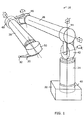
- FIG. 1 illustrates one embodiment coordinate measuring machine (CMM) 10.
- the CMM 10 comprises a base 20, a plurality of rigid transfer members 24, 26, 28, a coordinate acquisition member 30 and a plurality of articulation members 40, 42, 44, 46, 48, 50 connecting the rigid transfer members 24, 26, 28 to one another.
- Each articulation member is configured to impart one or more rotational and/or angular degrees of freedom.
- the CMM 10 can be aligned in various spatial orientations thereby allowing fine positioning of the coordinate acquisition member 110 in three dimensional space.
- the position of the rigid transfer members 24, 26, 28 and the coordinate acquisition member 30 may be adjusted using manual, robotic, semi-robotic and/or any other adjustment method.
- the CMM 10, through the various articulation members is provided with seven rotary axes of movement. It will be appreciated, however, that there is no strict limitation to the number of axes of movement that may be used, and fewer or additional axes of movement may be incorporated into the CMM design.
- the coordinate acquisition member 30 comprises a contact sensitive member or probe 32 configured to engage the surfaces of a selected object and generate coordinate data on the basis of probe contact.
- the coordinate acquisition member 30 may comprise a remote scanning and detection component that does not necessarily require direct contact with the selected object to acquire geometry data.
- a laser coordinate detection device e.g., laser camera
- coordinate acquisition member configurations including: a contact-sensitive probe, a remote-scanning probe, a laser-scanning probe, a probe that uses a strain gauge for contact detection, a probe that uses a pressure sensor for contact detection, a probe that used an infrared beam for positioning, and a probe configured to be electrostatically-responsive may be used for the purposes of coordinate acquisition.
- one or more of the rigid transfer members 24, 26, 28 comprise a composite structure that includes an inner portion and an outer exoskeletal portion.
- the inner portions of the rigid transfer members 24, 26, 28 are interconnected to one another through articulation members 42, 44, 46, 48 that provide the ability to position the coordinate acquisition member 30 in a variety of different orientations in three dimensional space.
- the rigid transfer members 24, 26, 28 can likewise be coupled to the base 20 and the coordinate acquisition member 30 by articulation members 40, 50.
- the outer portions surrounding the various inner portions of the rigid transfer members 24, 26, 28 form an environmental barrier that at least partially encloses segments of the inner portions.
- the inner portions are configured to "float" inside the corresponding outer portions.
- the position of the probe 32 in space at a given instant can be calculated by knowing the length of each member and the specific position of each of the articulation members 40, 42, 44, 46, 48, 50.
- Each of the articulation members 40, 42, 44, 46, 48, 50 can be broken down into a singular rotational degree of motion, each of which is measured using a dedicated rotational transducer (e.g., an encoder or digital encoder).
- Each transducer outputs a signal, which varies according to the movement of the articulation members 40, 42, 44, 46, 48, 50 in its degree of motion.
- the signal can be carried through wires or otherwise transmitted to a the base 20.
- the transducer can comprise an optical, or digital encoder.
- each encoder measures the rotational position of its axle by coupling is movement to a pair of internal wheels having successive transparent and opaque bands.
- light can be shined through the wheels onto optical sensors which feed a pair of electrical outputs.
- the output of the analog encoder can be substantially two sinusoidal signals which are 90 degrees out of phase. Coarse positioning can occur through monitoring the change in polarity of the two signals. Fine positioning can be determined by measuring the actual value of the two signals at the instant in question. In certain embodiments, maximum accuracy can be obtained by measuring the output precisely before it is corrupted by electronic noise. Additional details and embodiments of the illustrated embodiment of the CMM 10 can be found in U.S. Patent No. 5,829,148 . As described in the '148 patent, one ore more of the joints are preferably configured for infinite rotation.
- one or more of the rigid transfer members 24, 26, 28 can be in the form of a dual concentric tubular structure having an inner tubular shaft rotatively mounted coaxially within an outer tubular sheath through one or more bearings mounted proximately to a first end of a member adjacent to a hinge joint (e.g., 42, 46) and one or more bearings located at an opposite end of the member.
- the use of cylindrical tubes for both sheath and shaft is preferred because they offer construction simplicity, rigidity, light weight, and space inside for the transducers, slip rings etc.
- the tubes are preferably made from a light-weight, rigid material such as epoxy bonded carbon graphite which inexpensively offers a strength to weight ratio in excess of that of steel. Another advantage of carbon graphite is that it has a low thermal expansion coefficient. Although temperature transducers are commonly used in coordinate measuring machines so as to compensate for the thermal expansion of the arm and the article being measured, errors in compensation are reduced in arms having a lower overall thermal expansion coefficient.
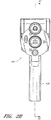
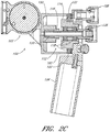
- FIGS. 2A-C are perspective, front and cross-sectional views of an improved embodiment of a final joint assembly 100 of a portable CMM (such as the embodiment described above).
- the joint assembly 100 can be part of a 2-2-3 portable CMM, where each numeral represents the number of axes of movement at a specified joint.
- a 2-2-3 portable CMM is a 7 axis CMM allowing 2 axes of rotation at a first joint, two axes of rotation at a second joint, and 3 axes of rotation at a final joint. It will be appreciated, however, that there is no strict limitation to the number of axes of movement that may be used, and fewer or additional axes of movement may be incorporated into the portable CMM.
- the assembly 100 includes a body 102 that is pivotably connected to the rest of the CMM 10 through joint 103 that rotates about a first axis of rotation 104.
- this first axis 104 can be the 6 th axis of a CMM. In other embodiments, additional or fewer axes can be provided.
- the first axis of rotation 104 comprises a pivot axis.
- the assembly 100 also includes a first probe 106, which can be, for example, a rigid probe, an electrical contact probe, a touch trigger probe, a strain sensing probe, a laser point probe, a laser line probe, an optical probe or other probe.
- the first probe 106 can be rigidly coupled to the body 102 and joint 103.
- a rotatable assembly 107 is journalled for rotation about a second axis 110 with respect to the body 102 and the probe 106.
- the assembly can also include a second probe 108, which can be, for example, a rigid probe, an electrical contact probe, a touch trigger probe, a strain sensing probe, a laser point probe, a laser line probe, an optical probe or other probe.
- the second probe comprises a laser scanner or other measurement device coupled to the assembly 107 such that the laser scanner can rotate about the second axis 110.
- the first probe 106 is fixed with respect to the last axis of rotation of the device while the second probe 108 moves with the last axis of rotation.
- the first probe 106 is a hard probe and the second probe 108 is a laser scanner.
- the specific type of probe can be modified.
- the second axis 110 can be the 7 th axis of rotation of the CMM and can be configured for swiveling rotation about the first probe 106.
- the rotation about the second axis 110 of the second probe 108 is independent of the first probe 106. This arrangement advantageously allows measurement with the first probe 106 to be more accurate because it does not involve the additional second axis transducer (which will be described below).
- the second probe 108 is however advantageously provided with the additional axis of movement.
- the rotatable assembly 107 can comprise an encoder 112.
- the encoder 112 can generally comprise an encoder disk and an encoder read head.
- the encoder 112 can comprise an encoder housing 114 and an encoder shaft 116.
- the encoder 112 includes one or more bearings 118 for supporting the shaft 116 with respect to the housing 114.
- the encoder read head can be positioned on the encoder shaft 116, and the encoder disk can be positioned on the encoder housing 114 such that the encoder can measure rotation of the encoder disk relative to the encoder read head.
- the encoder read head can be positioned on the encoder housing 114, and the encoder disk can be positioned on the encoder shaft 114.
- the encoder 112 does not have a specific shaft and housing upon which the encoder read head and encoder disk are positioned. Instead the read head and disk are positioned on components of the assembly 100 that rotate with respect to each other.
- the read head or the disk can be positioned on the rotatable assembly 107 while the corresponding disk or read head can be positioned on the non-rotatable body 102 or an component attached thereto.
- the second axis 110 can be defined as the axis of rotation between the encoder read head and the encoder disk.
- the encoder 112 can be one of a variety of types of encoders configured to measure rotational movement of the shaft with respect to the encoder housing.
- one end 120 of the encoder shaft 118 is non-rotatably coupled to the body 102.
- the encoder 112 housing is, in turn, journalled for rotation with respect to the body 102 by one or more bearings 122.
- the encoder housing 114 can rotate with respect to the body 102 while the encoder shaft 116 remains fixed with respect to the body 102 and the first axis of rotation 104.
- the second probe 108 and a handle 126 are coupled to the encoder housing 114 such that these components 108, 126 also rotate with respect to the body 102 of the assembly 100.
- the probe 106 can be coupled to a second end of the encoder shaft 116 and thus is non-rotably coupled to the second axis of rotation 104.
- the second end of the encoder shaft 116 extends through the encoder housing 114.
- a probe connector 128 can be provided between each of the first probe 106 and the shaft 116 and the second probe 108 and the housing 114.
- the probe connector 128 can include various electrical connectors for identifying the probe 106, 108 and/or receiving data from the first probe 106, which can be transferred via wires (not shown) through the encoder shaft 116, or, as noted below, via a slip ring 130, from the second probe 108.
- the assembly 100 can include a slip ring 130, which can be used to transmit data from the laser scanner 108 or other device on the second axis 110.
- the wiring (not shown) associated with the scanner 108 or other device on the assembly 107 can be passed internally through the joints of the CMM 10 and/or the assembly 107 can be rotated infinitely (see e.g., the '148 patent incorporated by reference herein).
- the assembly 100 can be configured without the slip ring and/or the wires can be passed externally of the CMM 10. In such embodiments, it may be advantageous to provide a stop or other type of motion limit in the assembly 100.
- assembly 100 includes two probes 106, 108, in some embodiments, it can be desirable to have more than two probes, such as three, four, or more probes.
- a first probe 106 can be rotationally fixed with respect to the second axis 110, while two or more additional probes are rotatable with respect to the second axis.
- more than one probe can be rotationally fixed with respect to the second axis 110, while a single probe is rotatable with respect to the second axis 110.
- a more than one probe can be rotatably fixed and more than one probe can be rotatable with respect to the second axis 110.
- the CMM 10 and final joint assembly 100 can be pre-assembled such that they are commercially available as a single unit. In other embodiments, the CMM 10 and final joint assembly 100 can be individually commercially available.
- the CMM 10 can also be configured such that the final axis of movement (i.e., the rotatable assembly 107) can be removed and/or added to an existing device.
- the CMM 10 and the rotatable assembly 107 can be easily removably couplable with a repeatable kinematic mount.
- the CMM can be a 6 axis (2-2-2) CMM with a kinematic mount allowing a rotatable joint assembly 107 to be mounted. The addition of the final joint assembly to the 6 axis CMM would create a 7 axis (2-2-3) CMM.
Claims (15)
- Articulation (100) pour un appareil de mesure de coordonnées (10) comprenant :• un corps d'articulation (102) pouvant être raccordé à un appareil de mesure de coordonnées (10) ;• une articulation rotative (107) définissant un axe de rotation (110) de l'articulation (100) ; et• un premier raccord de sonde (128) fixé en rotation par rapport au corps d'articulation (102) autour de l'axe de rotation (110) de l'articulation (100),caractérisée par
un second raccord de sonde (128) et un manche (126), tous deux rotatifs par rapport au corps d'articulation (102) autour de l'axe de rotation (110) de l'articulation (100). - Articulation (100) selon la revendication 1,
caractérisée par
une première sonde (106) couplée au premier raccord de sonde (128). - Articulation (100) selon la revendication 2,
caractérisée en ce que
la première sonde (106) comprend l'une d'une sonde rigide, d'une sonde de contact électrique, d'une sonde à déclenchement tactile, d'une sonde de détection d'effort, d'une sonde à point laser, d'une sonde à raie laser, et d'une sonde optique. - Articulation (100) selon la revendication 2,
caractérisée par
une seconde sonde (108) couplée au second raccord de sonde (128). - Articulation (100) selon la revendication 4,
caractérisée en ce que
la seconde sonde (108) comprend l'une d'une sonde rigide, d'une sonde de contact électrique, d'une sonde à déclenchement tactile, d'une sonde de détection d'effort, d'une sonde à point laser, d'une sonde à raie laser, et d'une sonde optique. - Articulation (100) selon la revendication 1,
caractérisée en ce que
l'articulation (100) est configurée pour pouvoir être couplée de façon amovible à l'appareil de mesure de coordonnées (10). - Articulation (100) selon la revendication 1,
caractérisée par
une tête de lecture et un disque encodeur, le disque encodeur étant configuré pour tourner autour de l'axe de rotation (110) de l'articulation (100) par rapport à la tête de lecture. - Appareil de mesure de coordonnées (10) comprenant• un bras articulé ayant une première extrémité, une seconde extrémité, et une pluralité de segments de bras à articulation (24, 26, 28) entre elles, chaque segment de bras (24, 26, 28) incluant au moins un transducteur de position ; et• un ensemble mesure couplé à la seconde extrémité du bras,caractérisé en ce que
l'ensemble mesure comprend l'articulation (100) selon l'une quelconque des revendications précédentes. - Appareil de mesure de coordonnées selon la revendication 8,
caractérisé en ce que
ledit bras inclut 7 axes de rotation, dans lequel• l'ensemble mesure comprend une première articulation (103) fournissant un premier axe de rotation (104) entre la seconde extrémité du bras et un corps de l'ensemble sonde de mesure, et• le premier axe de rotation (104) et l'axe de rotation (110) de l'articulation (100) comprennent le 6e et le 7e axe de rotation respectivement. - Appareil de mesure de coordonnées selon la revendication 9,
caractérisé en ce que
les segments de bras à articulation (24, 26, 28) sont agencés selon une configuration d'articulation 2-2-3. - Appareil de mesure de coordonnées selon la revendication 8,
comprenant l'articulation selon la revendication 4,
caractérisé en ce que
la seconde sonde (108) est un lecteur laser. - Appareil de mesure de coordonnées selon la revendication 8,
comprenant l'articulation selon la revendication 2,
caractérisé en ce que
la première sonde (106) est une sonde tactile. - Appareil de mesure de coordonnées selon la revendication 8,
comprenant l'articulation selon la revendication 2,
caractérisé en ce que
la première sonde (106) est une sonde rigide. - Appareil de mesure de coordonnées selon la revendication 8,
comprenant l'articulation selon la revendication 4,
caractérisé par
une bague collectrice (130) configurée pour transmettre des données à partir de la seconde sonde (108). - Appareil de mesure de coordonnées selon la revendication 8,
caractérisé en ce que
l'ensemble mesure est couplé de manière amovible au bras articulé.
Applications Claiming Priority (2)
| Application Number | Priority Date | Filing Date | Title |
|---|---|---|---|
| US87172906P | 2006-12-22 | 2006-12-22 | |
| PCT/US2007/088735 WO2008080142A1 (fr) | 2006-12-22 | 2007-12-21 | Axe d'articulation amélioré pour machine de mesure de coordonnées |
Publications (3)
| Publication Number | Publication Date |
|---|---|
| EP2095061A1 EP2095061A1 (fr) | 2009-09-02 |
| EP2095061A4 EP2095061A4 (fr) | 2014-10-22 |
| EP2095061B1 true EP2095061B1 (fr) | 2019-02-20 |
Family
ID=39562959
Family Applications (1)
| Application Number | Title | Priority Date | Filing Date |
|---|---|---|---|
| EP07855336.9A Active EP2095061B1 (fr) | 2006-12-22 | 2007-12-21 | Axe d'articulation amélioré pour machine de mesure de coordonnées |
Country Status (4)
| Country | Link |
|---|---|
| US (1) | US7624510B2 (fr) |
| EP (1) | EP2095061B1 (fr) |
| JP (2) | JP5511387B2 (fr) |
| WO (1) | WO2008080142A1 (fr) |
Families Citing this family (75)
| Publication number | Priority date | Publication date | Assignee | Title |
|---|---|---|---|---|
| US7693325B2 (en) | 2004-01-14 | 2010-04-06 | Hexagon Metrology, Inc. | Transprojection of geometry data |
| GB0424729D0 (en) * | 2004-11-09 | 2004-12-08 | Crampton Stephen | Probe end module for articulated arms |
| DE102006031580A1 (de) | 2006-07-03 | 2008-01-17 | Faro Technologies, Inc., Lake Mary | Verfahren und Vorrichtung zum dreidimensionalen Erfassen eines Raumbereichs |
| US7743524B2 (en) | 2006-11-20 | 2010-06-29 | Hexagon Metrology Ab | Coordinate measurement machine with improved joint |
| US7779548B2 (en) | 2008-03-28 | 2010-08-24 | Hexagon Metrology, Inc. | Coordinate measuring machine with rotatable grip |
| US8122610B2 (en) * | 2008-03-28 | 2012-02-28 | Hexagon Metrology, Inc. | Systems and methods for improved coordination acquisition member comprising calibration information |
| US7765707B2 (en) * | 2008-07-10 | 2010-08-03 | Nikon Metrology Nv | Connection device for articulated arm measuring machines |
| US7908757B2 (en) * | 2008-10-16 | 2011-03-22 | Hexagon Metrology, Inc. | Articulating measuring arm with laser scanner |
| DE102009015920B4 (de) | 2009-03-25 | 2014-11-20 | Faro Technologies, Inc. | Vorrichtung zum optischen Abtasten und Vermessen einer Umgebung |
| US9551575B2 (en) | 2009-03-25 | 2017-01-24 | Faro Technologies, Inc. | Laser scanner having a multi-color light source and real-time color receiver |
| US8082673B2 (en) | 2009-11-06 | 2011-12-27 | Hexagon Metrology Ab | Systems and methods for control and calibration of a CMM |
| US8020308B2 (en) * | 2009-05-29 | 2011-09-20 | General Electric Company | Non-destructive inspection system having self-aligning probe assembly |
| EP2449353B1 (fr) | 2009-06-30 | 2019-09-11 | Hexagon Technology Center GmbH | Système de bras articulé avec détection de vibration et procédé de fonctionnement correspondant |
| US9210288B2 (en) | 2009-11-20 | 2015-12-08 | Faro Technologies, Inc. | Three-dimensional scanner with dichroic beam splitters to capture a variety of signals |
| DE102009057101A1 (de) | 2009-11-20 | 2011-05-26 | Faro Technologies, Inc., Lake Mary | Vorrichtung zum optischen Abtasten und Vermessen einer Umgebung |
| US9113023B2 (en) | 2009-11-20 | 2015-08-18 | Faro Technologies, Inc. | Three-dimensional scanner with spectroscopic energy detector |
| US9529083B2 (en) | 2009-11-20 | 2016-12-27 | Faro Technologies, Inc. | Three-dimensional scanner with enhanced spectroscopic energy detector |
| US20110213247A1 (en) * | 2010-01-08 | 2011-09-01 | Hexagon Metrology, Inc. | Articulated arm with imaging device |
| US8630314B2 (en) | 2010-01-11 | 2014-01-14 | Faro Technologies, Inc. | Method and apparatus for synchronizing measurements taken by multiple metrology devices |
| US9879976B2 (en) | 2010-01-20 | 2018-01-30 | Faro Technologies, Inc. | Articulated arm coordinate measurement machine that uses a 2D camera to determine 3D coordinates of smoothly continuous edge features |
| US9628775B2 (en) | 2010-01-20 | 2017-04-18 | Faro Technologies, Inc. | Articulated arm coordinate measurement machine having a 2D camera and method of obtaining 3D representations |
| US9607239B2 (en) | 2010-01-20 | 2017-03-28 | Faro Technologies, Inc. | Articulated arm coordinate measurement machine having a 2D camera and method of obtaining 3D representations |
| US8875409B2 (en) | 2010-01-20 | 2014-11-04 | Faro Technologies, Inc. | Coordinate measurement machines with removable accessories |
| US8832954B2 (en) | 2010-01-20 | 2014-09-16 | Faro Technologies, Inc. | Coordinate measurement machines with removable accessories |
| US8284407B2 (en) | 2010-01-20 | 2012-10-09 | Faro Technologies, Inc. | Coordinate measuring machine having an illuminated probe end and method of operation |
| US8898919B2 (en) | 2010-01-20 | 2014-12-02 | Faro Technologies, Inc. | Coordinate measurement machine with distance meter used to establish frame of reference |
| US8615893B2 (en) | 2010-01-20 | 2013-12-31 | Faro Technologies, Inc. | Portable articulated arm coordinate measuring machine having integrated software controls |
| US8677643B2 (en) | 2010-01-20 | 2014-03-25 | Faro Technologies, Inc. | Coordinate measurement machines with removable accessories |
| US9163922B2 (en) | 2010-01-20 | 2015-10-20 | Faro Technologies, Inc. | Coordinate measurement machine with distance meter and camera to determine dimensions within camera images |
| JP5192614B1 (ja) | 2010-01-20 | 2013-05-08 | ファロ テクノロジーズ インコーポレーテッド | 座標測定デバイス |
| GB2490631B (en) * | 2010-01-20 | 2016-11-02 | Faro Tech Inc | Portable articulated arm coordinate measuring machine with multi-bus arm technology |
| USD643319S1 (en) | 2010-03-29 | 2011-08-16 | Hexagon Metrology Ab | Portable coordinate measurement machine |
| DE102010020925B4 (de) | 2010-05-10 | 2014-02-27 | Faro Technologies, Inc. | Verfahren zum optischen Abtasten und Vermessen einer Umgebung |
| US8127458B1 (en) | 2010-08-31 | 2012-03-06 | Hexagon Metrology, Inc. | Mounting apparatus for articulated arm laser scanner |
| DE112011102995B4 (de) | 2010-09-08 | 2016-05-19 | Faro Technologies Inc. | Laserscanner oder Lasernachführungsgerät mit einem Projektor |
| US9168654B2 (en) | 2010-11-16 | 2015-10-27 | Faro Technologies, Inc. | Coordinate measuring machines with dual layer arm |
| JP5616210B2 (ja) * | 2010-12-09 | 2014-10-29 | 株式会社ミツトヨ | 形状測定システム及び形状測定方法 |
| US8763267B2 (en) | 2012-01-20 | 2014-07-01 | Hexagon Technology Center Gmbh | Locking counterbalance for a CMM |
| DE102012100609A1 (de) | 2012-01-25 | 2013-07-25 | Faro Technologies, Inc. | Vorrichtung zum optischen Abtasten und Vermessen einer Umgebung |
| US9069355B2 (en) | 2012-06-08 | 2015-06-30 | Hexagon Technology Center Gmbh | System and method for a wireless feature pack |
| US8997362B2 (en) | 2012-07-17 | 2015-04-07 | Faro Technologies, Inc. | Portable articulated arm coordinate measuring machine with optical communications bus |
| US10067231B2 (en) | 2012-10-05 | 2018-09-04 | Faro Technologies, Inc. | Registration calculation of three-dimensional scanner data performed between scans based on measurements by two-dimensional scanner |
| DE102012109481A1 (de) | 2012-10-05 | 2014-04-10 | Faro Technologies, Inc. | Vorrichtung zum optischen Abtasten und Vermessen einer Umgebung |
| US9513107B2 (en) | 2012-10-05 | 2016-12-06 | Faro Technologies, Inc. | Registration calculation between three-dimensional (3D) scans based on two-dimensional (2D) scan data from a 3D scanner |
| US9250214B2 (en) | 2013-03-12 | 2016-02-02 | Hexagon Metrology, Inc. | CMM with flaw detection system |
| TWI551268B (zh) * | 2013-11-22 | 2016-10-01 | 國立陽明大學 | 可攜式關節附屬動作量化裝置 |
| US9163921B2 (en) | 2013-12-18 | 2015-10-20 | Hexagon Metrology, Inc. | Ultra-portable articulated arm coordinate measurement machine |
| US9594250B2 (en) | 2013-12-18 | 2017-03-14 | Hexagon Metrology, Inc. | Ultra-portable coordinate measurement machine |
| US9829305B2 (en) | 2014-05-14 | 2017-11-28 | Faro Technologies, Inc. | Metrology device and method of changing operating system |
| US9921046B2 (en) | 2014-05-14 | 2018-03-20 | Faro Technologies, Inc. | Metrology device and method of servicing |
| US9803969B2 (en) | 2014-05-14 | 2017-10-31 | Faro Technologies, Inc. | Metrology device and method of communicating with portable devices |
| US9746308B2 (en) | 2014-05-14 | 2017-08-29 | Faro Technologies, Inc. | Metrology device and method of performing an inspection |
| US9903701B2 (en) * | 2014-05-14 | 2018-02-27 | Faro Technologies, Inc. | Articulated arm coordinate measurement machine having a rotary switch |
| US9759540B2 (en) | 2014-06-11 | 2017-09-12 | Hexagon Metrology, Inc. | Articulating CMM probe |
| US10073062B2 (en) | 2014-09-05 | 2018-09-11 | General Electric Company | System and method for inspecting flange connections |
| EP3194884B1 (fr) | 2014-09-19 | 2023-11-01 | Hexagon Metrology, Inc | Machine de mesure de coordonnées portative multi-mode |
| DE102015122844A1 (de) | 2015-12-27 | 2017-06-29 | Faro Technologies, Inc. | 3D-Messvorrichtung mit Batteriepack |
| US11054237B2 (en) | 2019-04-04 | 2021-07-06 | Sa08700334 | Ultra-light and ultra-accurate portable coordinate measurement machine with unique base plate arrangement |
| US11566880B2 (en) | 2017-04-13 | 2023-01-31 | Sa08700334 | Ultra-light and ultra-accurate portable coordinate measurement machine substantially immune to bearing assembly thermal effects |
| US10267614B2 (en) | 2017-04-13 | 2019-04-23 | Sa08700334 | Ultra-light and ultra-accurate portable coordinate measurement machine |
| US10634478B2 (en) | 2017-04-13 | 2020-04-28 | Sa08700334 | Ultra-light and ultra-accurate portable coordinate measurement machine with serial bus capture |
| US9803973B1 (en) | 2017-04-13 | 2017-10-31 | Sa08700334 | Ultra-light and ultra-accurate portable coordinate measurement machine |
| US11092419B2 (en) | 2017-04-13 | 2021-08-17 | Sa08700334 | Ultra-light and ultra-accurate portable coordinate measurement machine with multi-piece joint engagement |
| US11022434B2 (en) | 2017-11-13 | 2021-06-01 | Hexagon Metrology, Inc. | Thermal management of an optical scanning device |
| FR3083602B1 (fr) | 2018-07-06 | 2020-09-18 | Hexagon Metrology Sas | Bras de mesure avec extremite multifonction |
| FR3083604B1 (fr) * | 2018-07-06 | 2020-09-18 | Hexagon Metrology Sas | Bras de mesure avec extremite multifonction |
| FR3083603B1 (fr) * | 2018-07-06 | 2020-11-20 | Hexagon Metrology Sas | Bras de mesure avec extremite multifonction |
| FR3083605B1 (fr) | 2018-07-06 | 2020-09-18 | Hexagon Metrology Sas | Bras de mesure avec extremite multifonction |
| FR3083600B1 (fr) | 2018-07-06 | 2020-09-18 | Hexagon Metrology Sas | Bras de mesure avec extremite multifonction |
| FR3083601B1 (fr) | 2018-07-06 | 2020-09-18 | Hexagon Metrology Sas | Bras de mesure avec extremite multifonction |
| US11073373B2 (en) * | 2018-08-22 | 2021-07-27 | Government Of The United States Of America, As Represented By The Secretary Of Commerce | Non-contact coordinate measuring machine using a noncontact metrology probe |
| USD875573S1 (en) | 2018-09-26 | 2020-02-18 | Hexagon Metrology, Inc. | Scanning device |
| CN110567592A (zh) * | 2019-10-14 | 2019-12-13 | 上海江南轧辊有限公司 | 一种远距离测温仪支架 |
| GB201915100D0 (en) * | 2019-10-18 | 2019-12-04 | Renishaw Plc | Coordinate positioning machine |
| US11747126B1 (en) | 2022-05-20 | 2023-09-05 | Sa08700334 | Ultra-light and ultra-accurate portable coordinate measurement machine with reduced profile swivel joints |
Citations (1)
| Publication number | Priority date | Publication date | Assignee | Title |
|---|---|---|---|---|
| US20060129349A1 (en) * | 2002-02-14 | 2006-06-15 | Simon Raab | Portable coordinate measurement machine with integrated line laser scanner |
Family Cites Families (54)
| Publication number | Priority date | Publication date | Assignee | Title |
|---|---|---|---|---|
| CA1299362C (fr) * | 1986-12-10 | 1992-04-28 | Gregory James Mcdonald | Systeme de mesure de coordonnees |
| EP0392699B1 (fr) * | 1989-04-14 | 1993-09-22 | Renishaw plc | Tête de palpeur |
| EP0392660B1 (fr) * | 1989-04-14 | 1993-09-08 | Renishaw plc | Tête de palpeur |
| JPH02290506A (ja) * | 1989-04-28 | 1990-11-30 | Mitsutoyo Corp | 三次元測定機 |
| FR2674017B1 (fr) * | 1991-03-12 | 1995-01-13 | Romer Srl | Dispositif de mesure de forme ou de position d'un objet. |
| CH683032A5 (de) | 1991-06-26 | 1993-12-31 | Escher Wyss Ag | Vorrichtung zur Bestimmung einer Flächenkontur. |
| DE4327250C5 (de) * | 1992-09-25 | 2008-11-20 | Carl Zeiss Industrielle Messtechnik Gmbh | Verfahren zur Koordinatenmessung an Werkstücken |
| DE4238139C2 (de) * | 1992-11-12 | 2002-10-24 | Zeiss Carl | Koordinatenmeßgerät |
| GB2274526A (en) | 1993-01-21 | 1994-07-27 | Motorola Inc | Verifying geometry of a part |
| US5408754A (en) * | 1993-02-23 | 1995-04-25 | Faro Technologies, Inc. | Method and apparatus for measuring sleeping positions |
| US5611147A (en) * | 1993-02-23 | 1997-03-18 | Faro Technologies, Inc. | Three dimensional coordinate measuring apparatus |
| US5412880A (en) * | 1993-02-23 | 1995-05-09 | Faro Technologies Inc. | Method of constructing a 3-dimensional map of a measurable quantity using three dimensional coordinate measuring apparatus |
| US6535794B1 (en) * | 1993-02-23 | 2003-03-18 | Faro Technologoies Inc. | Method of generating an error map for calibration of a robot or multi-axis machining center |
| US5724264A (en) * | 1993-07-16 | 1998-03-03 | Immersion Human Interface Corp. | Method and apparatus for tracking the position and orientation of a stylus and for digitizing a 3-D object |
| FR2710407B1 (fr) * | 1993-09-20 | 1995-12-01 | Romer Srl | Procédé de repérage positionnel pour une machine de mesure tridimensionnelle et dispositif pour la mise en Óoeuvre du procédé. |
| US5505003A (en) * | 1993-10-08 | 1996-04-09 | M&M Precision Systems Corporation | Generative measuring system |
| DE4345091C2 (de) | 1993-12-31 | 1995-10-05 | Perthen Feinpruef Gmbh | Meßtaster mit mehrdimensionalem Tastsystem |
| FR2721395B1 (fr) * | 1994-06-17 | 1996-08-14 | Homer Eaton | Procédé de repérage positionnel d'un trièdre dans l'espace et dispositif pour la mise en Óoeuvre de ce procédé. |
| US5521847A (en) * | 1994-07-01 | 1996-05-28 | General Electric Company | System and method for determining airfoil characteristics from coordinate measuring machine probe center data |
| US5510977A (en) * | 1994-08-02 | 1996-04-23 | Faro Technologies Inc. | Method and apparatus for measuring features of a part or item |
| US5822450A (en) * | 1994-08-31 | 1998-10-13 | Kabushiki Kaisha Toshiba | Method for monitoring equipment state by distribution measurement data, and equipment monitoring apparatus |
| GB9515311D0 (en) * | 1995-07-26 | 1995-09-20 | 3D Scanners Ltd | Stripe scanners and methods of scanning |
| FR2740546B1 (fr) | 1995-10-25 | 1998-01-02 | Romer Srl | Dispositif de mesure tridimensionnelle pour vehicule accidente |
| US5768792A (en) * | 1996-02-09 | 1998-06-23 | Faro Technologies Inc. | Method and apparatus for measuring and tube fitting |
| US5829148A (en) * | 1996-04-23 | 1998-11-03 | Eaton; Homer L. | Spatial measuring device |
| US6161079A (en) * | 1997-08-18 | 2000-12-12 | Giddings & Lewis, Llc | Method and apparatus for determining tolerance and nominal measurement values for a coordinate measuring machine |
| JP3126114B2 (ja) * | 1997-11-12 | 2001-01-22 | 株式会社ミツトヨ | 非接触表面粗さ測定装置 |
| US5991704A (en) * | 1998-03-26 | 1999-11-23 | Chrysler Corporation | Flexible support with indicator device |
| DE19816270A1 (de) * | 1998-04-11 | 1999-10-21 | Werth Messtechnik Gmbh | Verfahren und Anordnung zur Erfassung der Geometrie von Gegenständen mittels eines Koordinatenmeßgeräts |
| US6151789A (en) * | 1998-07-01 | 2000-11-28 | Faro Technologies Inc. | Adjustable handgrip for a coordinate measurement machine |
| US5978748A (en) * | 1998-07-07 | 1999-11-02 | Faro Technologies, Inc. | Host independent articulated arm |
| US6219928B1 (en) * | 1998-07-08 | 2001-04-24 | Faro Technologies Inc. | Serial network for coordinate measurement apparatus |
| JP2000035325A (ja) * | 1998-07-16 | 2000-02-02 | Mitsutoyo Corp | 洗浄装置付測定機 |
| DE29918341U1 (de) * | 1999-10-18 | 2001-03-01 | Tassakos Charalambos | Vorrichtung zur Positionsbestimmung von Meßpunkten eines Meßobjekts relativ zu einem Bezugssystem |
| FR2806657B1 (fr) * | 2000-03-21 | 2002-08-16 | Romain Granger | Systeme de reperage positionnel d'une machine tridimensionnelle dans un referentiel fixe |
| US6668466B1 (en) * | 2000-10-19 | 2003-12-30 | Sandia Corporation | Highly accurate articulated coordinate measuring machine |
| DE10112977C1 (de) | 2001-03-17 | 2002-11-21 | Zett Mess Technik Gmbh | Höhenmess- und Anreißgerät |
| US6598306B2 (en) * | 2001-04-17 | 2003-07-29 | Homer L. Eaton | Self-loading spatial reference point array |
| US6984236B2 (en) * | 2001-10-24 | 2006-01-10 | Faro Technologies, Inc. | Bone connective prosthesis and method of forming same |
| US6957496B2 (en) * | 2002-02-14 | 2005-10-25 | Faro Technologies, Inc. | Method for improving measurement accuracy of a portable coordinate measurement machine |
| US6965843B2 (en) * | 2002-02-14 | 2005-11-15 | Faro Technologies, Inc. | Portable coordinate measurement machine with integrated line laser scanner |
| US6952882B2 (en) * | 2002-02-14 | 2005-10-11 | Faro Technologies, Inc. | Portable coordinate measurement machine |
| US7073271B2 (en) * | 2002-02-14 | 2006-07-11 | Faro Technologies Inc. | Portable coordinate measurement machine |
| US6973734B2 (en) * | 2002-02-14 | 2005-12-13 | Faro Technologies, Inc. | Method for providing sensory feedback to the operator of a portable measurement machine |
| DE60306902T2 (de) * | 2002-02-26 | 2007-01-11 | Faro Technologies, Inc., Lake Mary | Standhafter vakuumadapter |
| US6640458B2 (en) * | 2002-03-25 | 2003-11-04 | Btm Corporation | End arm effector set-up |
| US6817108B2 (en) * | 2003-02-05 | 2004-11-16 | Homer L. Eaton | Articulation measuring arm having rotatable part-carrying platen |
| US7003892B2 (en) * | 2003-04-15 | 2006-02-28 | Hexagon Metrology Ab | Spatial coordinate-based method for identifying work pieces |
| GB2417090A (en) * | 2003-04-28 | 2006-02-15 | Stephen James Crampton | CMM arm with exoskeleton |
| FR2861843B1 (fr) * | 2003-10-29 | 2006-07-07 | Romain Granger | Dispositif de connexion associe a un bras d'appareil de mesure tridimentionnelle a bras articules |
| US7152456B2 (en) * | 2004-01-14 | 2006-12-26 | Romer Incorporated | Automated robotic measuring system |
| GB0424729D0 (en) * | 2004-11-09 | 2004-12-08 | Crampton Stephen | Probe end module for articulated arms |
| WO2006121562A1 (fr) * | 2005-04-11 | 2006-11-16 | Faro Technologies, Inc. | Dispositif de mesure de coordonnees tridimensionnelles |
| WO2007033273A2 (fr) * | 2005-09-13 | 2007-03-22 | Romer Incorporated | Véhicule muni d’un dispositif d’articulation |
-
2007
- 2007-12-21 WO PCT/US2007/088735 patent/WO2008080142A1/fr active Application Filing
- 2007-12-21 JP JP2009543282A patent/JP5511387B2/ja active Active
- 2007-12-21 US US11/963,531 patent/US7624510B2/en active Active
- 2007-12-21 EP EP07855336.9A patent/EP2095061B1/fr active Active
-
2013
- 2013-11-11 JP JP2013233319A patent/JP2014066714A/ja not_active Withdrawn
Patent Citations (1)
| Publication number | Priority date | Publication date | Assignee | Title |
|---|---|---|---|---|
| US20060129349A1 (en) * | 2002-02-14 | 2006-06-15 | Simon Raab | Portable coordinate measurement machine with integrated line laser scanner |
Also Published As
| Publication number | Publication date |
|---|---|
| JP2010515028A (ja) | 2010-05-06 |
| US7624510B2 (en) | 2009-12-01 |
| EP2095061A4 (fr) | 2014-10-22 |
| EP2095061A1 (fr) | 2009-09-02 |
| WO2008080142A1 (fr) | 2008-07-03 |
| US20090013548A1 (en) | 2009-01-15 |
| JP2014066714A (ja) | 2014-04-17 |
| JP5511387B2 (ja) | 2014-06-04 |
Similar Documents
| Publication | Publication Date | Title |
|---|---|---|
| EP2095061B1 (fr) | Axe d'articulation amélioré pour machine de mesure de coordonnées | |
| US10317186B2 (en) | Articulating CMM probe | |
| US7774949B2 (en) | Coordinate measurement machine | |
| US9250214B2 (en) | CMM with flaw detection system | |
| JP5886513B2 (ja) | レーザスキャナを伴う関節式測定アーム | |
| US9989348B2 (en) | Systems and methods for control and calibration of a CMM | |
| EP2092269B1 (fr) | Machine de mesure de coordonnées avec joint amélioré | |
| EP2612104B1 (fr) | Appareil de montage pour scanneur laser à bras articulé |
Legal Events
| Date | Code | Title | Description |
|---|---|---|---|
| PUAI | Public reference made under article 153(3) epc to a published international application that has entered the european phase |
Free format text: ORIGINAL CODE: 0009012 |
|
| 17P | Request for examination filed |
Effective date: 20090630 |
|
| AK | Designated contracting states |
Kind code of ref document: A1 Designated state(s): AT BE BG CH CY CZ DE DK EE ES FI FR GB GR HU IE IS IT LI LT LU LV MC MT NL PL PT RO SE SI SK TR |
|
| RIN1 | Information on inventor provided before grant (corrected) |
Inventor name: FERRARI, PAUL A. |
|
| DAX | Request for extension of the european patent (deleted) | ||
| RAP1 | Party data changed (applicant data changed or rights of an application transferred) |
Owner name: HEXAGON METROLOGY, INC |
|
| RAP1 | Party data changed (applicant data changed or rights of an application transferred) |
Owner name: HEXAGON METROLOGY, INC |
|
| A4 | Supplementary search report drawn up and despatched |
Effective date: 20140919 |
|
| RIC1 | Information provided on ipc code assigned before grant |
Ipc: G01B 5/012 20060101ALI20140915BHEP Ipc: G01B 5/20 20060101AFI20140915BHEP |
|
| STAA | Information on the status of an ep patent application or granted ep patent |
Free format text: STATUS: EXAMINATION IS IN PROGRESS |
|
| 17Q | First examination report despatched |
Effective date: 20170811 |
|
| GRAP | Despatch of communication of intention to grant a patent |
Free format text: ORIGINAL CODE: EPIDOSNIGR1 |
|
| STAA | Information on the status of an ep patent application or granted ep patent |
Free format text: STATUS: GRANT OF PATENT IS INTENDED |
|
| RIC1 | Information provided on ipc code assigned before grant |
Ipc: G01B 5/012 20060101ALI20180124BHEP Ipc: G01B 21/04 20060101ALI20180124BHEP Ipc: G01B 5/20 20060101AFI20180124BHEP |
|
| INTG | Intention to grant announced |
Effective date: 20180213 |
|
| GRAS | Grant fee paid |
Free format text: ORIGINAL CODE: EPIDOSNIGR3 |
|
| GRAA | (expected) grant |
Free format text: ORIGINAL CODE: 0009210 |
|
| STAA | Information on the status of an ep patent application or granted ep patent |
Free format text: STATUS: THE PATENT HAS BEEN GRANTED |
|
| AK | Designated contracting states |
Kind code of ref document: B1 Designated state(s): AT BE BG CH CY CZ DE DK EE ES FI FR GB GR HU IE IS IT LI LT LU LV MC MT NL PL PT RO SE SI SK TR |
|
| REG | Reference to a national code |
Ref country code: GB Ref legal event code: FG4D |
|
| REG | Reference to a national code |
Ref country code: CH Ref legal event code: EP |
|
| REG | Reference to a national code |
Ref country code: DE Ref legal event code: R096 Ref document number: 602007057653 Country of ref document: DE |
|
| REG | Reference to a national code |
Ref country code: AT Ref legal event code: REF Ref document number: 1098767 Country of ref document: AT Kind code of ref document: T Effective date: 20190315 |
|
| REG | Reference to a national code |
Ref country code: IE Ref legal event code: FG4D |
|
| REG | Reference to a national code |
Ref country code: CH Ref legal event code: NV Representative=s name: KAMINSKI HARMANN PATENTANWAELTE AG, LI |
|
| REG | Reference to a national code |
Ref country code: NL Ref legal event code: FP |
|
| REG | Reference to a national code |
Ref country code: LT Ref legal event code: MG4D |
|
| PG25 | Lapsed in a contracting state [announced via postgrant information from national office to epo] |
Ref country code: LT Free format text: LAPSE BECAUSE OF FAILURE TO SUBMIT A TRANSLATION OF THE DESCRIPTION OR TO PAY THE FEE WITHIN THE PRESCRIBED TIME-LIMIT Effective date: 20190220 Ref country code: FI Free format text: LAPSE BECAUSE OF FAILURE TO SUBMIT A TRANSLATION OF THE DESCRIPTION OR TO PAY THE FEE WITHIN THE PRESCRIBED TIME-LIMIT Effective date: 20190220 Ref country code: PT Free format text: LAPSE BECAUSE OF FAILURE TO SUBMIT A TRANSLATION OF THE DESCRIPTION OR TO PAY THE FEE WITHIN THE PRESCRIBED TIME-LIMIT Effective date: 20190620 Ref country code: SE Free format text: LAPSE BECAUSE OF FAILURE TO SUBMIT A TRANSLATION OF THE DESCRIPTION OR TO PAY THE FEE WITHIN THE PRESCRIBED TIME-LIMIT Effective date: 20190220 |
|
| PG25 | Lapsed in a contracting state [announced via postgrant information from national office to epo] |
Ref country code: BG Free format text: LAPSE BECAUSE OF FAILURE TO SUBMIT A TRANSLATION OF THE DESCRIPTION OR TO PAY THE FEE WITHIN THE PRESCRIBED TIME-LIMIT Effective date: 20190520 Ref country code: LV Free format text: LAPSE BECAUSE OF FAILURE TO SUBMIT A TRANSLATION OF THE DESCRIPTION OR TO PAY THE FEE WITHIN THE PRESCRIBED TIME-LIMIT Effective date: 20190220 Ref country code: GR Free format text: LAPSE BECAUSE OF FAILURE TO SUBMIT A TRANSLATION OF THE DESCRIPTION OR TO PAY THE FEE WITHIN THE PRESCRIBED TIME-LIMIT Effective date: 20190521 Ref country code: IS Free format text: LAPSE BECAUSE OF FAILURE TO SUBMIT A TRANSLATION OF THE DESCRIPTION OR TO PAY THE FEE WITHIN THE PRESCRIBED TIME-LIMIT Effective date: 20190620 |
|
| REG | Reference to a national code |
Ref country code: AT Ref legal event code: MK05 Ref document number: 1098767 Country of ref document: AT Kind code of ref document: T Effective date: 20190220 |
|
| PG25 | Lapsed in a contracting state [announced via postgrant information from national office to epo] |
Ref country code: SK Free format text: LAPSE BECAUSE OF FAILURE TO SUBMIT A TRANSLATION OF THE DESCRIPTION OR TO PAY THE FEE WITHIN THE PRESCRIBED TIME-LIMIT Effective date: 20190220 Ref country code: ES Free format text: LAPSE BECAUSE OF FAILURE TO SUBMIT A TRANSLATION OF THE DESCRIPTION OR TO PAY THE FEE WITHIN THE PRESCRIBED TIME-LIMIT Effective date: 20190220 Ref country code: DK Free format text: LAPSE BECAUSE OF FAILURE TO SUBMIT A TRANSLATION OF THE DESCRIPTION OR TO PAY THE FEE WITHIN THE PRESCRIBED TIME-LIMIT Effective date: 20190220 Ref country code: EE Free format text: LAPSE BECAUSE OF FAILURE TO SUBMIT A TRANSLATION OF THE DESCRIPTION OR TO PAY THE FEE WITHIN THE PRESCRIBED TIME-LIMIT Effective date: 20190220 Ref country code: RO Free format text: LAPSE BECAUSE OF FAILURE TO SUBMIT A TRANSLATION OF THE DESCRIPTION OR TO PAY THE FEE WITHIN THE PRESCRIBED TIME-LIMIT Effective date: 20190220 Ref country code: CZ Free format text: LAPSE BECAUSE OF FAILURE TO SUBMIT A TRANSLATION OF THE DESCRIPTION OR TO PAY THE FEE WITHIN THE PRESCRIBED TIME-LIMIT Effective date: 20190220 |
|
| REG | Reference to a national code |
Ref country code: DE Ref legal event code: R097 Ref document number: 602007057653 Country of ref document: DE |
|
| PG25 | Lapsed in a contracting state [announced via postgrant information from national office to epo] |
Ref country code: PL Free format text: LAPSE BECAUSE OF FAILURE TO SUBMIT A TRANSLATION OF THE DESCRIPTION OR TO PAY THE FEE WITHIN THE PRESCRIBED TIME-LIMIT Effective date: 20190220 |
|
| PLBE | No opposition filed within time limit |
Free format text: ORIGINAL CODE: 0009261 |
|
| STAA | Information on the status of an ep patent application or granted ep patent |
Free format text: STATUS: NO OPPOSITION FILED WITHIN TIME LIMIT |
|
| PG25 | Lapsed in a contracting state [announced via postgrant information from national office to epo] |
Ref country code: AT Free format text: LAPSE BECAUSE OF FAILURE TO SUBMIT A TRANSLATION OF THE DESCRIPTION OR TO PAY THE FEE WITHIN THE PRESCRIBED TIME-LIMIT Effective date: 20190220 |
|
| 26N | No opposition filed |
Effective date: 20191121 |
|
| PGFP | Annual fee paid to national office [announced via postgrant information from national office to epo] |
Ref country code: NL Payment date: 20191226 Year of fee payment: 13 |
|
| PG25 | Lapsed in a contracting state [announced via postgrant information from national office to epo] |
Ref country code: SI Free format text: LAPSE BECAUSE OF FAILURE TO SUBMIT A TRANSLATION OF THE DESCRIPTION OR TO PAY THE FEE WITHIN THE PRESCRIBED TIME-LIMIT Effective date: 20190220 |
|
| PG25 | Lapsed in a contracting state [announced via postgrant information from national office to epo] |
Ref country code: TR Free format text: LAPSE BECAUSE OF FAILURE TO SUBMIT A TRANSLATION OF THE DESCRIPTION OR TO PAY THE FEE WITHIN THE PRESCRIBED TIME-LIMIT Effective date: 20190220 |
|
| PGFP | Annual fee paid to national office [announced via postgrant information from national office to epo] |
Ref country code: CH Payment date: 20191231 Year of fee payment: 13 |
|
| REG | Reference to a national code |
Ref country code: BE Ref legal event code: MM Effective date: 20191231 |
|
| PG25 | Lapsed in a contracting state [announced via postgrant information from national office to epo] |
Ref country code: MC Free format text: LAPSE BECAUSE OF FAILURE TO SUBMIT A TRANSLATION OF THE DESCRIPTION OR TO PAY THE FEE WITHIN THE PRESCRIBED TIME-LIMIT Effective date: 20190220 |
|
| PG25 | Lapsed in a contracting state [announced via postgrant information from national office to epo] |
Ref country code: LU Free format text: LAPSE BECAUSE OF NON-PAYMENT OF DUE FEES Effective date: 20191221 Ref country code: IE Free format text: LAPSE BECAUSE OF NON-PAYMENT OF DUE FEES Effective date: 20191221 |
|
| PG25 | Lapsed in a contracting state [announced via postgrant information from national office to epo] |
Ref country code: BE Free format text: LAPSE BECAUSE OF NON-PAYMENT OF DUE FEES Effective date: 20191231 |
|
| PG25 | Lapsed in a contracting state [announced via postgrant information from national office to epo] |
Ref country code: CY Free format text: LAPSE BECAUSE OF FAILURE TO SUBMIT A TRANSLATION OF THE DESCRIPTION OR TO PAY THE FEE WITHIN THE PRESCRIBED TIME-LIMIT Effective date: 20190220 |
|
| PG25 | Lapsed in a contracting state [announced via postgrant information from national office to epo] |
Ref country code: MT Free format text: LAPSE BECAUSE OF FAILURE TO SUBMIT A TRANSLATION OF THE DESCRIPTION OR TO PAY THE FEE WITHIN THE PRESCRIBED TIME-LIMIT Effective date: 20190220 Ref country code: HU Free format text: LAPSE BECAUSE OF FAILURE TO SUBMIT A TRANSLATION OF THE DESCRIPTION OR TO PAY THE FEE WITHIN THE PRESCRIBED TIME-LIMIT; INVALID AB INITIO Effective date: 20071221 |
|
| REG | Reference to a national code |
Ref country code: CH Ref legal event code: PL |
|
| REG | Reference to a national code |
Ref country code: NL Ref legal event code: MM Effective date: 20210101 |
|
| PG25 | Lapsed in a contracting state [announced via postgrant information from national office to epo] |
Ref country code: NL Free format text: LAPSE BECAUSE OF NON-PAYMENT OF DUE FEES Effective date: 20210101 |
|
| PG25 | Lapsed in a contracting state [announced via postgrant information from national office to epo] |
Ref country code: CH Free format text: LAPSE BECAUSE OF NON-PAYMENT OF DUE FEES Effective date: 20201231 Ref country code: LI Free format text: LAPSE BECAUSE OF NON-PAYMENT OF DUE FEES Effective date: 20201231 |
|
| PGFP | Annual fee paid to national office [announced via postgrant information from national office to epo] |
Ref country code: DE Payment date: 20221228 Year of fee payment: 16 |
|
| PGFP | Annual fee paid to national office [announced via postgrant information from national office to epo] |
Ref country code: GB Payment date: 20231227 Year of fee payment: 17 |
|
| PGFP | Annual fee paid to national office [announced via postgrant information from national office to epo] |
Ref country code: IT Payment date: 20231220 Year of fee payment: 17 Ref country code: FR Payment date: 20231227 Year of fee payment: 17 |