EP2094895B1 - Water-conducting household appliance having a treatment container assembled from at least two components - Google Patents
Water-conducting household appliance having a treatment container assembled from at least two components Download PDFInfo
- Publication number
- EP2094895B1 EP2094895B1 EP07822276A EP07822276A EP2094895B1 EP 2094895 B1 EP2094895 B1 EP 2094895B1 EP 07822276 A EP07822276 A EP 07822276A EP 07822276 A EP07822276 A EP 07822276A EP 2094895 B1 EP2094895 B1 EP 2094895B1
- Authority
- EP
- European Patent Office
- Prior art keywords
- components
- mechanical connection
- connection
- sealing element
- domestic appliance
- Prior art date
- Legal status (The legal status is an assumption and is not a legal conclusion. Google has not performed a legal analysis and makes no representation as to the accuracy of the status listed.)
- Active
Links
- 239000000463 material Substances 0.000 claims abstract description 10
- 238000007789 sealing Methods 0.000 claims description 54
- 229910000831 Steel Inorganic materials 0.000 claims description 8
- 230000000694 effects Effects 0.000 claims description 8
- 239000010959 steel Substances 0.000 claims description 8
- 229920003023 plastic Polymers 0.000 claims description 5
- 239000004033 plastic Substances 0.000 claims description 5
- VYZAMTAEIAYCRO-UHFFFAOYSA-N Chromium Chemical compound [Cr] VYZAMTAEIAYCRO-UHFFFAOYSA-N 0.000 claims description 4
- 239000000853 adhesive Substances 0.000 claims description 4
- 230000001070 adhesive effect Effects 0.000 claims description 4
- 239000011651 chromium Substances 0.000 claims description 4
- VNNRSPGTAMTISX-UHFFFAOYSA-N chromium nickel Chemical compound [Cr].[Ni] VNNRSPGTAMTISX-UHFFFAOYSA-N 0.000 claims description 4
- 229910052804 chromium Inorganic materials 0.000 claims description 2
- 238000005260 corrosion Methods 0.000 description 15
- 230000007797 corrosion Effects 0.000 description 15
- 238000005516 engineering process Methods 0.000 description 13
- 239000007788 liquid Substances 0.000 description 5
- 238000004519 manufacturing process Methods 0.000 description 5
- PXHVJJICTQNCMI-UHFFFAOYSA-N nickel Substances [Ni] PXHVJJICTQNCMI-UHFFFAOYSA-N 0.000 description 5
- 238000003466 welding Methods 0.000 description 5
- JEIPFZHSYJVQDO-UHFFFAOYSA-N iron(III) oxide Inorganic materials O=[Fe]O[Fe]=O JEIPFZHSYJVQDO-UHFFFAOYSA-N 0.000 description 4
- 238000005406 washing Methods 0.000 description 4
- 229910000669 Chrome steel Inorganic materials 0.000 description 3
- 238000004851 dishwashing Methods 0.000 description 3
- 238000000034 method Methods 0.000 description 3
- 229910052759 nickel Inorganic materials 0.000 description 3
- XLYOFNOQVPJJNP-UHFFFAOYSA-N water Substances O XLYOFNOQVPJJNP-UHFFFAOYSA-N 0.000 description 3
- 238000004026 adhesive bonding Methods 0.000 description 2
- 230000015572 biosynthetic process Effects 0.000 description 2
- 239000002131 composite material Substances 0.000 description 2
- 239000012530 fluid Substances 0.000 description 2
- 238000005304 joining Methods 0.000 description 2
- 230000035515 penetration Effects 0.000 description 2
- 229910001220 stainless steel Inorganic materials 0.000 description 2
- 230000000007 visual effect Effects 0.000 description 2
- 150000001875 compounds Chemical class 0.000 description 1
- 238000010276 construction Methods 0.000 description 1
- 238000002788 crimping Methods 0.000 description 1
- 238000005520 cutting process Methods 0.000 description 1
- 230000001419 dependent effect Effects 0.000 description 1
- 230000001747 exhibiting effect Effects 0.000 description 1
- 238000009434 installation Methods 0.000 description 1
- 229910052751 metal Inorganic materials 0.000 description 1
- 239000002184 metal Substances 0.000 description 1
- 238000004080 punching Methods 0.000 description 1
- 238000010008 shearing Methods 0.000 description 1
- 239000010935 stainless steel Substances 0.000 description 1
Images

Classifications
-
- A—HUMAN NECESSITIES
- A47—FURNITURE; DOMESTIC ARTICLES OR APPLIANCES; COFFEE MILLS; SPICE MILLS; SUCTION CLEANERS IN GENERAL
- A47L—DOMESTIC WASHING OR CLEANING; SUCTION CLEANERS IN GENERAL
- A47L15/00—Washing or rinsing machines for crockery or tableware
- A47L15/42—Details
- A47L15/4246—Details of the tub
-
- A—HUMAN NECESSITIES
- A47—FURNITURE; DOMESTIC ARTICLES OR APPLIANCES; COFFEE MILLS; SPICE MILLS; SUCTION CLEANERS IN GENERAL
- A47L—DOMESTIC WASHING OR CLEANING; SUCTION CLEANERS IN GENERAL
- A47L15/00—Washing or rinsing machines for crockery or tableware
- A47L15/42—Details
- A47L15/421—Safety arrangements for preventing water damage
-
- D—TEXTILES; PAPER
- D06—TREATMENT OF TEXTILES OR THE LIKE; LAUNDERING; FLEXIBLE MATERIALS NOT OTHERWISE PROVIDED FOR
- D06F—LAUNDERING, DRYING, IRONING, PRESSING OR FOLDING TEXTILE ARTICLES
- D06F39/00—Details of washing machines not specific to a single type of machines covered by groups D06F9/00 - D06F27/00
- D06F39/12—Casings; Tubs
Definitions
- the invention relates to a water-conducting household appliance, in particular a dishwasher, with a treatment container which is composed of at least two components made of different materials.
- the treatment container of dishwashers is usually made of a stainless steel.
- the treatment tank often consists of at least two components.
- the so-called container shell forms the side walls and the roof of a container hood of the treatment container and is connected, for example, with a separately formed rear wall, which is also part of the container hood.
- This composite is finally connected to a rinse tub.
- the components of the treatment tank are made of a high-grade chrome-nickel (Cr-Ni) steel, which is relatively expensive.
- Cr-Ni chrome-nickel
- the use of chromium nickel steel ensures that the corrosion resistance is also ensured in areas of mechanical connection between the container shell and the rear wall, usually via a weld.
- a treatment container for a dishwasher in which the connection of the container roof and the container bottom pan takes place in each case with the side walls via a fold with inserted seal.
- the sealing effect ie a seal of a gap between the two components is carried out by a squeezing. It is questionable whether the sealing element can be pressed in the direction shown in the figures in the direction of the interior of the treatment container. It is also questionable whether the sealing element is not squeezed in the manner shown in the figures by the crimping in the region of the abutting components. Furthermore, it should be considered whether the sealing element on the side facing the Spülrauminneren intimately against the component walls, so that the desired seal is actually achieved.
- connection technology is shown in more detail, wherein the mechanical connection takes place in each case using a separate holding element, which in each case has an independent mechanical connection with the edge portions of the components to be joined.
- the holding elements are not arranged on the side protected against moisture.
- connection technologies using a separate holding element for connecting two mechanically separated components are further from the DE 812 130 known.
- connection technologies shown and described there in the figures are not all suitable for the use of water-conducting household appliances.
- connection of two metal components is known, wherein the mechanical connection is carried out using a laser welding. Furthermore, a sealing element is provided in a different section of the connection from the welding area.
- a dishwasher in which at the front end of the container hood a corrosion-resistant part is arranged with a sealing function for rinsing liquid.
- a dishwashing machine in which a part of a treatment container made of plastic is provided with a metallic appearance in order to visually enhance this.
- the WO 2006/010743 A1 discloses a dishwasher in which the treatment container is composed of different parts.
- a dishwashing machine which has at the front of its treatment container a frame part, which is positively connected to a container shell of the treatment container.
- a dishwasher in which a drain pan is pressed into a container bottom.
- the object of the present invention is to provide a water-conducting household appliance with a treatment container of at least two components, in which a crevice corrosion in the range of mechanically interconnected components can be reliably prevented.
- each of the two components has an edge portion, via which a mechanical connection of the two components is made, wherein the mechanical connection is made in a protected against moisture section.
- the mechanical connection is sealed by means of a sealing element on the side of the treatment tank facing the interior of the washing compartment, so that a space between the two components exposed to moisture, which has a capillary effect, is prevented, ie. a capillary gap-free design is achieved.
- the two components to be connected to one another may be, for example, the container roof and the side walls and / or the side walls and the washing tub and / or the side walls and the rear wall and / or two-part side walls and the like.
- the mechanical connection of the first and the second component takes place in the region of orthogonally meeting surfaces of the components, wherein the sealing element is arranged in a corner region and wherein the sealing element by the first and the second component in the direction of the Spülrauminneren side facing away from the corner at least partially , preferably intimately, is enclosed.
- This special connection technology for example between the container roof and side walls or container roof and rear wall of the treatment container allows a visually particularly homogeneous impression, a particularly simple installation and a particularly good protection against crevice corrosion.
- the mechanical connection can be formed according to an embodiment of the invention by a welded connection, an adhesive connection, a folded connection, a clamping connection or a flange. It is essential here that the mechanical connection of the two components is made in a protected against moisture section.
- the sealing element must therefore be arranged in an area in front of the mechanical connection.
- the mechanical connection can be formed in one embodiment in a region of overlapping edge portions of the components to be joined together.
- This connection technology allows a particularly simple production, since, for example, a welded or an adhesive connection can be used.
- the mechanical connection is performed using a holding element, which each has an independent mechanical connection with the edge portions of the components to be joined.
- the mechanical connection of the retaining element to the edge portions of the components to be connected can be done either by a welded or adhesive connection or preferably by a purely mechanical connection in the form of a fold, a clamp or a flange.
- this connection technology has the advantage that the visible to the user interior of the treatment container is essentially equipped with a smooth surface.
- connection between the components makes itself felt only by the visible sealing element for sealing a capillary effect having a gap between the components.
- the second variant may require a greater depth in comparison to the first-mentioned variant, so that the outer housing of the water-conducting device has a greater distance from the treatment vessel.
- the sealing element between the first and the second component is clamped under application of a force, so that the sealing element bears intimately against the opposing surfaces of the components.
- the force is thereby applied by the mechanical connection of the first and second components.
- the clamping process ensures that squeezing of the sealing element during the production of the mechanical connection between the first and the second component can not occur, so that an intimate contact of the sealing element on the opposite surfaces of the Components results. As a result, a gap having a capillary effect can be reliably avoided.
- the sealing element may be provided to arrange the sealing element in a recess of the first and / or second component adapted to the cross-section thereof. This results in a particularly simple production, since the seat of the sealing element is determined from the outset due to the shape of the component or components. On the other hand, by sinking a part of the sealing element an improved visual impression for a user of the water-bearing household appliance can be ensured.
- a further embodiment provides that the profile of the overlapping of the edge portions of the first and the second component in the region of the side walls is horizontal and the overlap of the edge portions is such that the edge portion of the running in the direction of the container roof part of the Spipporauminneren and the edge portion of the Container bottom extending component facing the Spülraumauseren, so that the arranged between the edge portions sealing element is oriented towards the bottom pan. Due to the rinsing fluid running in the direction of the rinsing tub, the sealing element does not need to exert any actual sealing function with respect to the rinsing fluid. It must primarily counteract the capillary forces, which is particularly easy as the seal is placed in a moisture-proof area.
- a further embodiment provides that the seal bears against a fold formed on the edge section. This ensures that the, e.g. by a punching or cutting process resulting end faces of the components, which are particularly susceptible to rust, not facing the Spülrauminneren. This results in an improved rust protection. In addition, it is ensured that there are no sharp edges in the interior of the dishwasher accessible to the user.
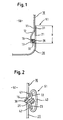
- Fig. 1 is a section of a treatment container of a water-conducting household appliance shown.
- a component 10 which represents, for example, a side wall of the treatment container, is made of a simple chrome steel, which is connected to a second component 20, a, for example, chromium-nickel steel or plastic rinse tub.
- the reference numeral 50 indicates the Spülrauminninnere the treatment tank.
- the first component 10 has an edge portion 11 and the second component 20 has an edge portion 21.
- an overlap of the two components takes place, which is characterized by the arrow provided with the reference numeral B.
- the mechanical connection of the two components 10, 20 takes place, wherein this is carried out in a moisture-protected section.
- the connection at the point indicated by the reference numeral 31 can take place, for example, by means of a welded or glued connection.
- the component 10 is provided with a fold 13 in the region directed downwards towards the component 20. Between the surface formed by the fold 13 and an opposite surface 26 in the edge portion 21 of the component 20, a sealing element 30, for example made of rubber, rubber or plastic, is clamped.
- the sealing element which bears intimately against the surfaces 16, 26, prevents ingress of liquid in the direction of the mechanical connection point (reference numeral 31).
- the sealing element prevents a direct contiguity of the components made of different corrosion-resistant materials 10, 20. If the components 10, 20 are mechanically connected directly in the region of the sealing element 30, would without the provision of further sealing measures on the container interior 50 side facing a Interspace be formed, in which due to the capillary effect could penetrate rinsing liquid. Over a longer period of time, this could result in rust, in particular in the less corrosion-resistant material, which on the one hand would impair the visual impression of the interior of the washing compartment and, on the other hand, the functionality.
- the sealing member 30 at the position shown in the figure thus prevents the formation of a gap between the two components 10, 20, whereby crevice corrosion is effectively prevented.
- the per se unfavorable connection method of welding can also be used between chrome steel and chrome nickel steel.
- FIG. 2 shows a further embodiment of a compound of the two components 10, 20, which, as in the embodiment described above, consist of two different materials.
- Each of the components 10, 20 has a fold 13, 23 into which the ends 41, 42 of a holding element 40 engage.
- the holding element 40 is arranged on the side facing away from the Spülrauminneren 50 side of the treatment vessel.
- the prone to corrosion region between the fold 13 and the end 41 of the holding member 40 and the fold 23 and the end 42 of the holding member 40 is thereby reliably protected from moisture.
- the mechanical connection between the ends 41, 42 and the folded ends 13, 23 the components 10, 20 can be effected by a clamping, gluing or welding connection.
- a sealing element 30 is provided, which is clamped between the folded ends of the folds (surfaces 16, 26).
- the force applied by the holding element for connecting the components 10, 20 and thus for clamping and deforming the sealing element 30 is just so great that an intimate contact of the sealing element 30 with the surfaces 16, 26 takes place, but squeezing off or shearing off the sealing element excluded is.
- the turn of rubber, plastic or rubber or other suitable material existing sealing element may be formed in its original cross-section round, elliptical or already provided with constrictions.
- FIG. 3 Another embodiment is in the Fig. 3 shown.
- the connection of the first component 10 and the second component 20 takes place here in a corner region 52 of the treatment container.
- the sealing element 30 is thus arranged on the Spül inconvenienceerinneren 50 facing corner, for example between the container wall and container roof or container wall and rinse tub.
- the second component 20 is provided, for example, with a recess 24, which is adapted to the cross-sectional shape of the sealing element 30.
- the sealing element 30 is inserted into the recess 24 and lies intimately against the wall of the recess 24 (reference numeral 26).
- the component 10 is mechanically connected in the exemplary embodiment via a flange 32 with the component 20.
- other joining technologies such as gluing, welding, folding or other would be considered.
- the component 10 is L-shaped, whereby the component portion 14 causes a deformation of the sealing element 30, whereby an intimate connection of the surface 16 is effected with the sealing element 30. Due to this construction, the penetration of moisture or rinsing liquid out of the washing compartment interior 50 in the direction of the mechanical fastening is reliably prevented, whereby a crevice corrosion occurring in the overlap region B is prevented.
- connection technologies described in the embodiments come into consideration, in which it is ensured that the components to be interconnected in the interior of the Spülrauminneren have no direct, direct contact with each other, but about a sealing element are interconnected.
- the described embodiments have the common feature that the mechanical connection is located in a moisture-free area. As a result, in a region shielded by the sealing element against moisture, a mechanical connection can take place by means of any connection technology, regardless of whether or not it is suitable in principle for humid environments.
Abstract
Description
Die Erfindung betrifft ein wasserführendes Haushaltsgerät, insbesondere eine Geschirrspülmaschine, mit einem Behandlungsbehälter, der aus zumindest zwei Bauteilen aus unterschiedlichen Materialien zusammengesetzt ist.The invention relates to a water-conducting household appliance, in particular a dishwasher, with a treatment container which is composed of at least two components made of different materials.
Der Behandlungsbehälter von Geschirrspülmaschinen wird üblicherweise aus einem rostfreien Edelstahl gefertigt. Der Behandlungsbehälter besteht häufig aus wenigstens zwei Bestandteilen. Der so genannte Behältermantel bildet die Seitenwände sowie das Dach einer Behälterhaube des Behandlungsbehälters aus und ist beispielsweise mit einer separat ausgebildeten Rückwand, die ebenfalls Bestandteil der Behälterhaube ist, verbunden. Dieser Verbund wird schließlich mit einer Spülwanne verbunden. Aus Gründen der Korrosionsbeständigkeit werden die Bestandteile des Behandlungsbehälters aus einem hochwertigen Chromnickel (Cr-Ni)-Stahl gefertigt, welcher verhältnismäßig teuer ist. Die Verwendung von Chromnickel-Stahl stellt sicher, dass die Korrosionsbeständigkeit auch in Bereichen mechanischer Verbindung zwischen dem Behältermantel und der Rückwand, üblicherweise über eine Schweißnaht, gewährleistet ist.The treatment container of dishwashers is usually made of a stainless steel. The treatment tank often consists of at least two components. The so-called container shell forms the side walls and the roof of a container hood of the treatment container and is connected, for example, with a separately formed rear wall, which is also part of the container hood. This composite is finally connected to a rinse tub. For reasons of corrosion resistance, the components of the treatment tank are made of a high-grade chrome-nickel (Cr-Ni) steel, which is relatively expensive. The use of chromium nickel steel ensures that the corrosion resistance is also ensured in areas of mechanical connection between the container shell and the rear wall, usually via a weld.
Aus fertigungstechnischer Sicht wäre es bevorzugt, wenn wesentliche Bestandteile des Behandlungsbehälters aus dem einfacheren Chrom(Cr)-Stahl gefertigt werden könnten, da dann die Kosten der Herstellung reduziert werden können. Die Problematik bei der Verbindung von Chrom-Stahl mit Chromnickel-Stahl über eine Schweißung besteht darin, dass bei wasserführenden Haushaltsgeräten, wie einer Geschirrspülmaschine, so genannte Spaltkorrosion im Verbindungsbereich auftreten kann. Das Auftreten von Spaltkorrosion ist ebenfalls bereits dann möglich, wenn die gesamte Behälterhaube aus einem Chrom-Stahl-Verbund gefertigt wird.From a manufacturing point of view, it would be preferable if essential components of the treatment container could be made of the simpler chromium (Cr) steel, since then the cost of production can be reduced. The problem with the connection of chromium steel with chrome nickel steel via a weld is that with water-bearing household appliances, such as a dishwasher, so-called crevice corrosion can occur in the connection area. The occurrence of crevice corrosion is also already possible if the entire container hood is made of a chrome-steel composite.
Zur Vermeidung von Spaltkorrosion werden deshalb besondere Verbindungstechnologien der zwei Bauteile des Behandlungsbehälters des wasserführenden Haushaltsgeräts benötigt.To avoid crevice corrosion therefore special connection technologies of the two components of the treatment container of the water-bearing household appliance are needed.
Aus der
Aus der
Verschiedene Verbindungstechnologien unter Verwendung eines separaten Halteelements zur Verbindung zweier mechanisch voneinander getrennter Bauteile sind ferner aus der
Aus der
Eine wasserdichte Verbindung durch ein Ineinandergreifen jeweils umgefalzter Randabschnitte zweier Bauteile wird durch die
Ferner ist aus der
Des weiteren ist aus der
Die
Aus der
Weiterhin ist aus der
Aus der
Aus der
Die Aufgabe der vorliegenden Erfindung besteht deshalb darin, ein wasserführendes Haushaltsgerät mit einem Behandlungsbehälter aus zumindest zwei Bauteilen anzugeben, bei dem eine Spaltkorrosion im Bereich der miteinander mechanisch verbundenen Bauteile zuverlässig verhindert werden kann.The object of the present invention is to provide a water-conducting household appliance with a treatment container of at least two components, in which a crevice corrosion in the range of mechanically interconnected components can be reliably prevented.
Diese Aufgabe wird mit einem wasserführenden Haushaltsgerät mit den Merkmalen des Patentanspruches 1 gelöst. Vorteilhafte Ausgestaltungen ergeben sich aus den abhängigen Patentansprüchen.This object is achieved with a water-conducting household appliance with the features of claim 1. Advantageous embodiments will be apparent from the dependent claims.
Bei dem erfindungsgemäßen wasserführenden Haushaltsgerät weist jedes der beiden Bauteile einen Randabschnitt auf, über welchen eine mechanische Verbindung der zwei Bauteile vorgenommen ist, wobei die mechanische Verbindung in einem gegenüber Feuchtigkeit geschützten Abschnitt vorgenommen ist. Die Abdichtung der mechanischen Verbindung erfolgt mittels eines Dichtelements auf der dem Spülrauminneren zugewandten Seite des Behandlungsbehälters, so dass ein Feuchtigkeit ausgesetzter, einen Kapillareffekt aufweisender Zwischenraum zwischen den beiden Bauteilen unterbunden ist, d.h. es wird eine kapilarspaltfreie Ausführung erreicht. Nachdem der Behandlungsbehälter aus zumindest zwei Bauteilen aus unterschiedlichen Materialien, die insbesondere hinsichtlich ihrer Rostbeständigkeit unterschiedliche Eigenschaften aufweisen, hergestellt werden soll, muss der Art der Abdichtung und der damit einhergehenden Verbindungstechnologie besondere Aufmerksamkeit geschenkt werden. Nachdem die Gefahr von Korrosion insbesondere durch eine Spaltbildung und die damit verbundenen Kapillareffekte auftritt, ist vorgesehen, das Dichtelement derart auf der dem Spülrauminneren des Behandlungsbehälters zugewandten Seite anzuordnen, dass ein solcher, einen Kapillareffekt aufweisender Zwischenraum zwischen den Bauteilen sicher unterbunden ist.In the water-conducting household appliance according to the invention, each of the two components has an edge portion, via which a mechanical connection of the two components is made, wherein the mechanical connection is made in a protected against moisture section. The mechanical connection is sealed by means of a sealing element on the side of the treatment tank facing the interior of the washing compartment, so that a space between the two components exposed to moisture, which has a capillary effect, is prevented, ie. a capillary gap-free design is achieved. After the treatment container of at least two components made of different materials, which have different properties, in particular with regard to their rust resistance, should be produced, the type of sealing and the associated connection technology must be given special attention. After the risk of corrosion occurs, in particular by a gap formation and the associated capillary effects, it is provided to arrange the sealing element on the side facing the Spülrauminneren of the treatment tank so that such, capillary effect exhibiting gap between the components is reliably prevented.
Bei den miteinander zu verbindenden zwei Bauteilen kann es sich beispielsweise um das Behälterdach und die Seitenwände und/oder die Seitenwände und die Spülwanne und/oder die Seitenwände und die Rückwand und/oder zweigeteilte Seitenwände und dergleichen handeln.The two components to be connected to one another may be, for example, the container roof and the side walls and / or the side walls and the washing tub and / or the side walls and the rear wall and / or two-part side walls and the like.
Dabei erfolgt die mechanische Verbindung des ersten und des zweiten Bauteils im Bereich orthogonal aufeinander treffender Flächen der Bauteile, wobei das Dichtelement in einem Eckbereich angeordnet ist und wobei das Dichtelement durch das erste und das zweite Bauteil in Richtung der vom Spülrauminneren abgewandten Seite der Ecke wenigstens teilweise, vorzugsweise innig, umschlossen ist. Diese besondere Verbindungstechnologie, z.B. zwischen Behälterdach und Seitenwänden bzw. Behälterdach und Rückwand des Behandlungsbehälters ermöglicht einen optisch besonders homogenen Eindruck, eine besonders einfache Montage sowie einen besonders guten Schutz gegen Spaltkorrosion.In this case, the mechanical connection of the first and the second component takes place in the region of orthogonally meeting surfaces of the components, wherein the sealing element is arranged in a corner region and wherein the sealing element by the first and the second component in the direction of the Spülrauminneren side facing away from the corner at least partially , preferably intimately, is enclosed. This special connection technology, for example between the container roof and side walls or container roof and rear wall of the treatment container allows a visually particularly homogeneous impression, a particularly simple installation and a particularly good protection against crevice corrosion.
Die mechanische Verbindung kann gemäß einer Ausgestaltung der Erfindung durch eine Schweißverbindung, eine Klebeverbindung, eine Falzverbindung, eine Klemmverbindung oder eine Bördelung gebildet sein. Wesentlich ist hierbei, dass die mechanische Verbindung der zwei Bauteile in einem gegenüber Feuchtigkeit geschützten Abschnitt vorgenommen ist. Das Dichtelement muss damit in einem Bereich vor der mechanischen Verbindung angeordnet sein.The mechanical connection can be formed according to an embodiment of the invention by a welded connection, an adhesive connection, a folded connection, a clamping connection or a flange. It is essential here that the mechanical connection of the two components is made in a protected against moisture section. The sealing element must therefore be arranged in an area in front of the mechanical connection.
Die mechanische Verbindung kann in einer Ausgestaltung in einem Bereich sich überlappender Randabschnitte der miteinander zu verbindenden Bauteile gebildet sein. Diese Verbindungstechnologie ermöglicht eine besonders einfache Herstellung, da beispielsweise eine Schweiß- oder eine Klebeverbindung zum Einsatz kommen kann. In einer anderen Ausgestaltung erfolgt die mechanische Verbindung unter Verwendung eines Halteelements, welches jeweils eine eigenständige mechanische Verbindung mit den Randabschnitten der zu verbindenden Bauteile aufweist. Die mechanische Verbindung des Halteelements zu den Randabschnitten der zu verbindenden Bauteile kann wahlweise durch eine Schweiß- oder Klebeverbindung oder bevorzugt durch eine rein mechanische Verbindung in Form eines Falzes, einer Klemmung oder einer Bördelung erfolgen. Gegenüber der erstgenannten Variante weist diese Verbindungstechnologie den Vorteil auf, dass der für den Nutzer sichtbare Innenraum des Behandlungsbehälters im wesentlichen mit einer glatten Oberfläche ausgestattet ist. Die Verbindung zwischen den Bauteilen macht sich lediglich durch das sichtbare Dichtelement zur Abdichtung eines einen Kapillareffekt aufweisenden Zwischenraums zwischen den Bauteilen bemerkbar. Andererseits benötigt die zweite Variante im Vergleich zur erstgenannten Variante gegebenenfalls eine größere Tiefe, so dass das Außengehäuse des wasserführenden Gerätes einen größeren Abstand zum Behandlungsbehälter aufweist.The mechanical connection can be formed in one embodiment in a region of overlapping edge portions of the components to be joined together. This connection technology allows a particularly simple production, since, for example, a welded or an adhesive connection can be used. In another embodiment, the mechanical connection is performed using a holding element, which each has an independent mechanical connection with the edge portions of the components to be joined. The mechanical connection of the retaining element to the edge portions of the components to be connected can be done either by a welded or adhesive connection or preferably by a purely mechanical connection in the form of a fold, a clamp or a flange. Compared with the first-mentioned variant, this connection technology has the advantage that the visible to the user interior of the treatment container is essentially equipped with a smooth surface. The connection between the components makes itself felt only by the visible sealing element for sealing a capillary effect having a gap between the components. On the other hand, the second variant may require a greater depth in comparison to the first-mentioned variant, so that the outer housing of the water-conducting device has a greater distance from the treatment vessel.
Besonders bevorzugt ist es, wenn das Dichtelement zwischen dem ersten und dem zweiten Bauteil unter Aufwendung einer Kraft eingeklemmt ist, so dass das Dichtelement innig an den sich gegenüberliegenden Flächen der Bauteile anliegt. Die Kraft wird hierdurch durch die mechanische Verbindung des ersten und zweiten Bauteils aufgebracht. Der Klemmvorgang stellt dabei sicher, dass ein Abquetschen des Dichtelementes während der Herstellung der mechanischen Verbindung zwischen dem ersten und dem zweiten Bauteil nicht auftreten kann, so dass sich eine innige Anlage des Dichtelementes an den sich gegenüberliegenden Flächen der Bauteile ergibt. Hierdurch kann zuverlässig ein einen Kapillareffekt aufweisender Zwischenraum vermieden werden.It is particularly preferred if the sealing element between the first and the second component is clamped under application of a force, so that the sealing element bears intimately against the opposing surfaces of the components. The force is thereby applied by the mechanical connection of the first and second components. The clamping process ensures that squeezing of the sealing element during the production of the mechanical connection between the first and the second component can not occur, so that an intimate contact of the sealing element on the opposite surfaces of the Components results. As a result, a gap having a capillary effect can be reliably avoided.
Gemäß einer weiteren Ausgestaltung kann vorgesehen sein, das Dichtelement in einer an deren Querschnitt angepassten Vertiefung des ersten und/oder zweiten Bauteils anzuordnen. Hierdurch ergibt sich eine besonders einfache Fertigung, da der Sitz des Dichtelementes von vornherein aufgrund der Form des oder der Bauteile festgelegt ist. Andererseits kann durch ein Versenken eines Teiles des Dichtelements ein verbesserter optischer Eindruck für einen Nutzer des wasserführenden Haushaltsgeräts sichergestellt werden.According to a further embodiment, it may be provided to arrange the sealing element in a recess of the first and / or second component adapted to the cross-section thereof. This results in a particularly simple production, since the seat of the sealing element is determined from the outset due to the shape of the component or components. On the other hand, by sinking a part of the sealing element an improved visual impression for a user of the water-bearing household appliance can be ensured.
Eine weitere Ausgestaltung sieht vor, dass der Verlauf der Überlappung der Randabschnitte des ersten und des zweiten Bauteils im Bereich der Seitenwände horizontal ist und die Überlappung der Randabschnitte derart ist, dass der Randabschnitt des in Richtung Behälterdach verlaufenden Bauteils des Spülrauminneren und der Randabschnitt des in Richtung Behälterboden verlaufenden Bauteils im Spülraumäußeren zugewandt ist, so dass das zwischen den Randabschnitten angeordnete Dichtelement in Richtung Bodenwanne orientiert ist. Das Dichtelement braucht dabei aufgrund der in Richtung Spülwanne laufenden Spülflüssigkeit keine eigentliche Abdichtfunktion gegenüber der Spülflüssigkeit auszuüben. Sie muss primär den Kapillarkräften entgegenwirken, was besonders einfach ist, da die Dichtung in einem gegenüber Feuchtigkeit angeordneten Bereich platziert ist.A further embodiment provides that the profile of the overlapping of the edge portions of the first and the second component in the region of the side walls is horizontal and the overlap of the edge portions is such that the edge portion of the running in the direction of the container roof part of the Spülrauminneren and the edge portion of the Container bottom extending component facing the Spülraumauseren, so that the arranged between the edge portions sealing element is oriented towards the bottom pan. Due to the rinsing fluid running in the direction of the rinsing tub, the sealing element does not need to exert any actual sealing function with respect to the rinsing fluid. It must primarily counteract the capillary forces, which is particularly easy as the seal is placed in a moisture-proof area.
Eine weitere Ausgestaltung sieht vor, dass die Dichtung an einem an dem Randabschnitt ausgebildeten Falz anliegt. Hierdurch ist sichergestellt, dass die, z.B. durch eine Stanzung oder einen Schneidvorgang entstehenden Stirnseiten der Bauteile, welche besonders gegenüber Rost anfällig sind, nicht dem Spülrauminneren zugewandt sind. Hierdurch ergibt sich ein verbesserter Rostschutz. Darüber hinaus ist sichergestellt, dass keine scharfen Kanten im für den Benutzer zugänglichen Spülrauminneren vorliegen.A further embodiment provides that the seal bears against a fold formed on the edge section. This ensures that the, e.g. by a punching or cutting process resulting end faces of the components, which are particularly susceptible to rust, not facing the Spülrauminneren. This results in an improved rust protection. In addition, it is ensured that there are no sharp edges in the interior of the dishwasher accessible to the user.
Die Erfindung wird nachfolgend anhand der Figuren näher erläutert. Es zeigen:
- Fig. 1
- ein erstes Ausführungsbeispiel einer mechanischen Verbindung zweier Bau- teile eines Behandlungsbehälters eines wasserführenden Haushaltsgeräts, bei dem die mechanische Verbindung in einem Bereich sich überlappender Randabschnitte der miteinander zu verbindenden Bauteile gebildet ist,
- Fig. 2
- ein zweites Ausführungsbeispiel einer mechanischen Verbindung zweier Bauteile eines Behandlungsbehälters eines wasserführenden Haushaltsge- räts, bei dem die mechanische Verbindung unter Verwendung eines Halt- elements erfolgt, und
- Fig. 3
- ein drittes Ausführungsbeispiel einer mechanischen Verbindung zweier Bau- teile eines Behandlungsbehälters eines wasserführenden Haushaltsgeräts, bei dem die mechanische Verbindung der beiden Bauteile in einem Bereich orthogonal aufeinander treffender Flächen in einem Eckbereich erfolgt.
- Fig. 1
- A first embodiment of a mechanical connection of two components of a treatment container of a water-conducting household appliance, in which the mechanical connection is formed in a region of overlapping edge sections of the components to be joined together,
- Fig. 2
- a second embodiment of a mechanical connection of two components of a treatment container of a water-carrying household appliance, in which the mechanical connection is carried out using a holding element, and
- Fig. 3
- a third embodiment of a mechanical connection of two components of a treatment container of a water-conducting household appliance, in which the mechanical connection of the two components in a region of orthogonally meeting surfaces in a corner occurs.
In
Das erste Bauteil 10 weist einen Randabschnitt 11 und das zweite Bauteil 20 weist einen Randabschnitt 21 auf. Im Bereich dieser Randabschnitte 11, 21 findet eine Überlappung der beiden Bauteile statt, was durch den mit dem Bezugszeichen B versehenen Pfeil gekennzeichnet ist. In diesem Überlappungsbereich B findet die mechanische Verbindung der beiden Bauteile 10, 20 statt, wobei diese in einem gegenüber Feuchtigkeit geschützten Abschnitt vorgenommen ist. Die Verbindung an der mit dem Bezugszeichen 31 gekennzeichneten Stelle kann beispielsweise mittels einer Schweiß- oder Klebeverbindung erfolgen.The
Das Bauteil 10 ist in dem nach unten zu Bauteil 20 gerichteten Bereich mit einem Falz 13 versehen. Zwischen der durch den Falz 13 ausgebildeten Fläche und einer gegenüberliegenden Fläche 26 im Randabschnitt 21 des Bauteils 20 ist ein Dichtelement 30, z.B. aus Gummi, Kautschuk oder Kunststoff, eingeklemmt. Das Dichtelement, welches innig an den Flächen 16, 26 anliegt, verhindert ein Eindringen von Flüssigkeit in Richtung der mechanischen Verbindungsstelle (Bezugszeichen 31).The
Ferner verhindert das Dichtelement ein unmittelbares Aneinandergrenzen der aus unterschiedlich korrosionsbeständigen Materialien bestehenden Bauteile 10, 20. Würden die Bauteile 10, 20 im Bereich des Dichtelementes 30 unmittelbar miteinander mechanisch verbunden werden, so würde ohne das Vorsehen weiterer Dichtmaßnahmen auf der zum Behälterinneren 50 gerichteten Seite ein Zwischenraum gebildet werden, in den aufgrund des Kapillareffekts Spülflüssigkeit eindringen könnte. Über einen längeren Zeitraum hinweg könnte dadurch insbesondere in dem weniger korrosionsbeständigen Material Rost auftreten, wodurch zum einen der optische Eindruck des Spülrauminneren und zum anderen die Funktionsfähigkeit beeinträchtigt würden.Further, the sealing element prevents a direct contiguity of the components made of different corrosion-
Das Vorsehen des Dichtelements 30 an der in der Figur gezeigten Stelle verhindert somit das Ausbilden eines Zwischenraums zwischen den beiden Bauteilen 10, 20, wodurch eine Spaltkorrosion wirksam verhindert ist. Auf diese Weise kann die an sich ungünstige Verbindungsmethode des Schweißens auch zwischen Chrom-Stahl und Chromnickel-Stahl verwendet werden. Nachdem das Dichtelement gegen unmittelbares Spritzwasser der Spülflüssigkeit geschützt angeordnet ist, ist die Gefahr des Eindringens von Feuchtigkeit in den zwischen den beiden Bauteilen 10, 20 gebildeten Zwischenraum nicht möglich, wodurch auch die mechanische Verbindung 31 keinen feuchtigkeitsbedingten Belastungen ausgesetzt ist.The provision of the sealing
In dem in
Ein weiteres Ausführungsbeispiel ist in der
Neben den in den Ausführungsbeispielen beschriebenen Verbindungstechnologien kommen auch weitere Verbindungstechnologien in Betracht, bei denen sichergestellt ist, dass die miteinander zu verbindenden Bauteile im Bereich des Spülrauminneren keinen unmittelbaren, direkten Kontakt zueinander aufweisen, sondern über ein Dichtelement miteinander verbunden sind. Die beschriebenen Ausführungsbeispiele haben die Gemeinsamkeit, dass die mechanische Verbindung in einem feuchtigkeitsfreien Bereich gelegen ist. Dadurch kann in einem durch das Dichtelement gegen Feuchtigkeit abgeschirmten Bereich eine mechanische Verbindung mittels einer beliebigen Verbindungstechnologie erfolgen, unabhängig davon, ob diese prinzipiell für feuchte Umgebungen geeignet ist oder nicht.In addition to the connection technologies described in the embodiments, other connection technologies come into consideration, in which it is ensured that the components to be interconnected in the interior of the Spülrauminneren have no direct, direct contact with each other, but about a sealing element are interconnected. The described embodiments have the common feature that the mechanical connection is located in a moisture-free area. As a result, in a region shielded by the sealing element against moisture, a mechanical connection can take place by means of any connection technology, regardless of whether or not it is suitable in principle for humid environments.
- 1010
- Bauteilcomponent
- 1111
- Randabschnittedge section
- 1212
- Kröpfungcranking
- 1313
- Falzfold
- 1414
- Bauteilabschnittcomponent section
- 1616
- Flächearea
- 2020
- Bauteilcomponent
- 2121
- Randabschnittedge section
- 2323
- Falzfold
- 2424
- Vertiefungdeepening
- 2626
- Flächearea
- 3030
- Dichtelementsealing element
- 3131
- Verbindungsstellejunction
- 3232
- Bördelflare
- 4141
- HalteelementendeRetaining element end
- 4242
- HalteelementendeEnd support member
- 5050
- SpülrauminneresSpülrauminneres
- 5151
- Feuchtigkeitsfreier BereichMoisture-free area
- 5252
- Eckbereichcorner
- BB
- Überlappungsbereichoverlap area
Claims (9)
- Water-conducting domestic appliance, particularly dishwasher, with a treatment container composed of at least two components (10, 20) of different materials, in which- each of the two components (10, 20) has an edge section (11, 21) by way of which a mechanical connection (31; 40; 32) of the two components (10, 20) is produced, wherein mechanical connection is produced in a section (51) protected against moisture from the rinsing chamber interior (50) of the treatment container,- sealing of the mechanical connection (31; 40; 32) against the moisture takes place by means of the sealing element (30) on the side, which faces the rinsing chamber interior (50), of the treatment container in such a manner that an intermediate space, which is exposed to the moisture and has a capillary effect, between the two components (10, 20) is prevented,characterised in that- the mechanical connection (31; 40; 32) of the first and second components (10, 20) is effected in the region of surfaces of the components impinging substantially orthogonally on one another and the sealing element (30) is arranged in a corner region (52) of the treatment container, wherein the sealing element is at least partly surrounded by the first and second components in the direction of the side of the corner remote from the rinsing chamber interior (51).
- Domestic appliance according to claim 1, characterised in that the mechanical connection (31; 40; 32) is formed in a region of mutually overlapping edge sections (B) of the two components (10, 20) to be connected together.
- Domestic appliance according to claim 1, characterised in that the mechanical connection (31; 40; 32) is effected with use of a holding element (40) which has a respective independent mechanical connection (11, 41, 21, 42) with each of the edge sections (11, 21) of the two components (10, 20) to be connected together.
- Domestic appliance according to any one of the preceding claims, characterised in that mechanical connection (31; 40; 32) is formed by a weld connection, an adhesive connection, a fold connection, a clamping connection or a flanging connection.
- Domestic appliance according to any one of the preceding claims, characterised in that the sealing element (30) is clamped in place between the first and second components (10, 20) with use of a force so that the sealing element (30) bears intimately against the opposite surfaces (16, 26) of the components.
- Domestic appliance according to any one of the preceding claims, characterised in that the sealing element (30) is arranged at a recess (24), which is matched to the cross-section thereof, of the first and/or second component.
- Domestic appliance according to any one of the preceding claims, characterised in that the path of the overlapping of the edge sections (11, 21) of the first and second components (10, 20) in the region of the side walls of the treatment container runs substantially horizontally and that the edge section of the first component, which runs in the direction of the container ceiling, faces the rinsing chamber interior and the edge section of the second component, which runs in the direction of the container floor, faces the rinsing chamber exterior.
- Domestic appliance according to any one of the preceding claims, characterised in that the seal (30) bears against a fold (13) formed at the edge section (11) of one of the two components (10, 20).
- Domestic appliance according to any one of the preceding claims, characterised in that the components (10, 20) to be connected together are made of one of the following materials: chromium (Cr) steel, chromium-nickel (CrNi) steel or plastics material.
Priority Applications (1)
| Application Number | Priority Date | Filing Date | Title |
|---|---|---|---|
| PL07822276T PL2094895T3 (en) | 2006-11-23 | 2007-11-07 | Water-conducting household appliance having a treatment container assembled from at least two components |
Applications Claiming Priority (2)
| Application Number | Priority Date | Filing Date | Title |
|---|---|---|---|
| DE102006055347A DE102006055347A1 (en) | 2006-11-23 | 2006-11-23 | Water-conducting household appliance with a treatment container composed of at least two components |
| PCT/EP2007/061960 WO2008061878A1 (en) | 2006-11-23 | 2007-11-07 | Water-conducting household appliance having a treatment container assembled from at least two components |
Publications (2)
| Publication Number | Publication Date |
|---|---|
| EP2094895A1 EP2094895A1 (en) | 2009-09-02 |
| EP2094895B1 true EP2094895B1 (en) | 2011-03-23 |
Family
ID=38926186
Family Applications (1)
| Application Number | Title | Priority Date | Filing Date |
|---|---|---|---|
| EP07822276A Active EP2094895B1 (en) | 2006-11-23 | 2007-11-07 | Water-conducting household appliance having a treatment container assembled from at least two components |
Country Status (8)
| Country | Link |
|---|---|
| US (1) | US9005370B2 (en) |
| EP (1) | EP2094895B1 (en) |
| KR (1) | KR20090087870A (en) |
| CN (1) | CN101529008B (en) |
| AT (1) | ATE503051T1 (en) |
| DE (2) | DE102006055347A1 (en) |
| PL (1) | PL2094895T3 (en) |
| WO (1) | WO2008061878A1 (en) |
Families Citing this family (10)
| Publication number | Priority date | Publication date | Assignee | Title |
|---|---|---|---|---|
| DE102007031478A1 (en) * | 2007-07-06 | 2009-01-08 | BSH Bosch und Siemens Hausgeräte GmbH | System kit for dishwasher inner container |
| DE102007041314B4 (en) * | 2007-08-31 | 2014-08-21 | BSH Bosch und Siemens Hausgeräte GmbH | Method for producing a water-conducting domestic appliance and water-conducting household appliance |
| JP5141697B2 (en) * | 2010-01-26 | 2013-02-13 | パナソニック株式会社 | dishwasher |
| DE102011004056A1 (en) | 2011-02-14 | 2012-08-16 | BSH Bosch und Siemens Hausgeräte GmbH | Dishwasher and method for producing a washing container of a dishwasher |
| US9155443B2 (en) | 2011-09-21 | 2015-10-13 | Whirlpool Corporation | Dishwasher with multi-piece tub |
| EP2950983B1 (en) | 2014-02-24 | 2016-08-24 | Koninklijke Philips N.V. | A rotary shaver comprising a disc-shaped element |
| DE102017209241B4 (en) * | 2017-05-31 | 2022-06-09 | BSH Hausgeräte GmbH | Rinse tank for a domestic dishwashing machine, domestic dishwashing machine and method |
| DE102017209244A1 (en) * | 2017-05-31 | 2018-12-06 | BSH Hausgeräte GmbH | Domestic dishwasher |
| DE102017209824B3 (en) * | 2017-06-09 | 2018-09-20 | BSH Hausgeräte GmbH | Washing container, method for producing a washing container and household dishwasher |
| DE102019213456A1 (en) * | 2019-09-04 | 2021-03-04 | BSH Hausgeräte GmbH | Household dishwasher |
Citations (4)
| Publication number | Priority date | Publication date | Assignee | Title |
|---|---|---|---|---|
| ES483274A1 (en) * | 1979-08-09 | 1980-04-01 | Balay Sa | Improvements introduced in the construction of dishwashers (Machine-translation by Google Translate, not legally binding) |
| DE3636437A1 (en) * | 1986-10-25 | 1988-05-05 | Licentia Gmbh | Dishwasher |
| US20060054195A1 (en) * | 2004-09-16 | 2006-03-16 | Lg Electronics Inc. | Dishwasher |
| EP1971251A1 (en) * | 2005-12-27 | 2008-09-24 | BSH Bosch und Siemens Hausgeräte GmbH | Dishwasher having a compartment cover made of low-cost steel, a frame part made of high-grade steel and a dishwasher tray made of plastic |
Family Cites Families (12)
| Publication number | Priority date | Publication date | Assignee | Title |
|---|---|---|---|---|
| DE812130C (en) * | 1949-01-11 | 1951-12-10 | Ahlmann Carlshuette K G | Detachable screwless connection for flat, wall-like parts made of metal or other materials |
| US3213583A (en) * | 1962-04-26 | 1965-10-26 | Winski Jack | Lock seam sheet metal panel |
| US3545147A (en) * | 1968-07-25 | 1970-12-08 | Winbro Inc | Sheet metal roofing panel |
| FI49248C (en) * | 1972-07-03 | 1975-05-12 | Valmet Oy | Folding procedure for sheet metal channels. |
| IT1083094B (en) * | 1977-07-08 | 1985-05-21 | Indesit | PROCEDURE FOR UNION BY SEALING THE CENTRAL BAND TO THE BOTTOM AND COVER OF A DISHWASHER MACHINE TANK |
| DE4017748C2 (en) * | 1990-06-01 | 1999-04-01 | Gebhardt Ventilatoren | Corner rebate |
| DE69311819T3 (en) | 1992-02-19 | 2004-01-29 | Merloni Elettrodomestici Spa | dishwasher |
| JPH08155564A (en) * | 1994-12-05 | 1996-06-18 | Toyota Motor Corp | Hemming structure, production of hemming and device therefor |
| DE10156423A1 (en) * | 2001-11-16 | 2003-06-05 | Bsh Bosch Siemens Hausgeraete | Two-part washing container for a dishwasher and method for producing a two-part washing container for a dishwasher |
| JP3750602B2 (en) * | 2001-12-25 | 2006-03-01 | 日本軽金属株式会社 | Watertight structure |
| DE102004035849A1 (en) | 2004-07-23 | 2006-03-16 | BSH Bosch und Siemens Hausgeräte GmbH | Dishwasher with modular design |
| DE202005016735U1 (en) | 2005-10-25 | 2006-01-05 | BSH Bosch und Siemens Hausgeräte GmbH | dishwasher |
-
2006
- 2006-11-23 DE DE102006055347A patent/DE102006055347A1/en not_active Ceased
-
2007
- 2007-11-07 PL PL07822276T patent/PL2094895T3/en unknown
- 2007-11-07 CN CN2007800394463A patent/CN101529008B/en active Active
- 2007-11-07 AT AT07822276T patent/ATE503051T1/en active
- 2007-11-07 US US12/515,313 patent/US9005370B2/en active Active
- 2007-11-07 KR KR1020097007816A patent/KR20090087870A/en not_active Application Discontinuation
- 2007-11-07 DE DE502007006804T patent/DE502007006804D1/en active Active
- 2007-11-07 EP EP07822276A patent/EP2094895B1/en active Active
- 2007-11-07 WO PCT/EP2007/061960 patent/WO2008061878A1/en active Application Filing
Patent Citations (4)
| Publication number | Priority date | Publication date | Assignee | Title |
|---|---|---|---|---|
| ES483274A1 (en) * | 1979-08-09 | 1980-04-01 | Balay Sa | Improvements introduced in the construction of dishwashers (Machine-translation by Google Translate, not legally binding) |
| DE3636437A1 (en) * | 1986-10-25 | 1988-05-05 | Licentia Gmbh | Dishwasher |
| US20060054195A1 (en) * | 2004-09-16 | 2006-03-16 | Lg Electronics Inc. | Dishwasher |
| EP1971251A1 (en) * | 2005-12-27 | 2008-09-24 | BSH Bosch und Siemens Hausgeräte GmbH | Dishwasher having a compartment cover made of low-cost steel, a frame part made of high-grade steel and a dishwasher tray made of plastic |
Also Published As
| Publication number | Publication date |
|---|---|
| ATE503051T1 (en) | 2011-04-15 |
| DE502007006804D1 (en) | 2011-05-05 |
| WO2008061878A1 (en) | 2008-05-29 |
| EP2094895A1 (en) | 2009-09-02 |
| CN101529008A (en) | 2009-09-09 |
| KR20090087870A (en) | 2009-08-18 |
| US20100132749A1 (en) | 2010-06-03 |
| US9005370B2 (en) | 2015-04-14 |
| PL2094895T3 (en) | 2011-08-31 |
| CN101529008B (en) | 2011-09-21 |
| DE102006055347A1 (en) | 2008-05-29 |
Similar Documents
| Publication | Publication Date | Title |
|---|---|---|
| EP2094895B1 (en) | Water-conducting household appliance having a treatment container assembled from at least two components | |
| EP1971251B1 (en) | Dishwasher having a compartment cover made of low-cost steel, a frame part made of high-grade steel and a dishwasher tray made of plastic | |
| EP1945090B1 (en) | Dishwasher with a plastic frame part which is fixed to a treatment container | |
| DE102007030064A1 (en) | Platform for a dishwasher | |
| EP1919345A1 (en) | Platform for a dish washing machine | |
| WO2007020241A2 (en) | Dishwasher platform | |
| EP2422680A2 (en) | Dishwasher | |
| EP2465403A2 (en) | Dishwasher | |
| DE102011003821B4 (en) | Dishwasher, in particular household dishwasher | |
| DE102017203978B4 (en) | Domestic dishwasher | |
| EP2484265B1 (en) | Method for manufacturing a dishwasher and dishwasher | |
| DE102011003820B4 (en) | Dishwasher, in particular household dishwasher | |
| DE102007017280A1 (en) | Method for manufacturing rinsing container for dishwashers, involves sectional interconnecting container rear wall and container frame along connecting area by joining process | |
| EP2465402B1 (en) | Dishwasher | |
| EP3003116B1 (en) | Connection arrangement, especially for a household appliance | |
| EP3629874B1 (en) | Washing container, domestic dishwasher, and method | |
| DE102011004222A1 (en) | Water-conducting domestic appliance, particularly dishwasher, comprises container, which is formed from primary container part and secondary container part, where primary container part comprises groove-shaped receptacle | |
| DE3036668C2 (en) | Connection piece for container or boiler | |
| DE102017209824B3 (en) | Washing container, method for producing a washing container and household dishwasher | |
| EP3629875B1 (en) | Washing container for a domestic dishwasher and domestic dishwasher | |
| DE102011086782B3 (en) | Dishwasher e.g. household dishwasher has plastic frame having integrally and firmly formed sealing lip bridged with vertical and/or horizontal mounting gap between dishwasher and adjacent furniture wall in dishwasher mounting position | |
| DE102008016484B4 (en) | Method for producing a device door | |
| DE102015226671A1 (en) | Door arrangement for a household appliance, method for producing a door assembly, receptacle for a household appliance and household appliance | |
| DE102013210026A1 (en) | Door assembly for a household appliance | |
| DE102010063433A1 (en) | Aquiferous domestic appliance e.g. dishwasher has container elements that are arranged one above the other in container cover to form container rear wall |
Legal Events
| Date | Code | Title | Description |
|---|---|---|---|
| PUAI | Public reference made under article 153(3) epc to a published international application that has entered the european phase |
Free format text: ORIGINAL CODE: 0009012 |
|
| 17P | Request for examination filed |
Effective date: 20090623 |
|
| AK | Designated contracting states |
Kind code of ref document: A1 Designated state(s): AT BE BG CH CY CZ DE DK EE ES FI FR GB GR HU IE IS IT LI LT LU LV MC MT NL PL PT RO SE SI SK TR |
|
| 17Q | First examination report despatched |
Effective date: 20091001 |
|
| DAX | Request for extension of the european patent (deleted) | ||
| GRAP | Despatch of communication of intention to grant a patent |
Free format text: ORIGINAL CODE: EPIDOSNIGR1 |
|
| GRAS | Grant fee paid |
Free format text: ORIGINAL CODE: EPIDOSNIGR3 |
|
| GRAA | (expected) grant |
Free format text: ORIGINAL CODE: 0009210 |
|
| AK | Designated contracting states |
Kind code of ref document: B1 Designated state(s): AT BE BG CH CY CZ DE DK EE ES FI FR GB GR HU IE IS IT LI LT LU LV MC MT NL PL PT RO SE SI SK TR |
|
| REG | Reference to a national code |
Ref country code: GB Ref legal event code: FG4D Free format text: NOT ENGLISH |
|
| REG | Reference to a national code |
Ref country code: CH Ref legal event code: EP |
|
| REG | Reference to a national code |
Ref country code: IE Ref legal event code: FG4D |
|
| REF | Corresponds to: |
Ref document number: 502007006804 Country of ref document: DE Date of ref document: 20110505 Kind code of ref document: P |
|
| REG | Reference to a national code |
Ref country code: DE Ref legal event code: R096 Ref document number: 502007006804 Country of ref document: DE Effective date: 20110505 |
|
| REG | Reference to a national code |
Ref country code: NL Ref legal event code: VDEP Effective date: 20110323 |
|
| PG25 | Lapsed in a contracting state [announced via postgrant information from national office to epo] |
Ref country code: GR Free format text: LAPSE BECAUSE OF FAILURE TO SUBMIT A TRANSLATION OF THE DESCRIPTION OR TO PAY THE FEE WITHIN THE PRESCRIBED TIME-LIMIT Effective date: 20110624 Ref country code: SE Free format text: LAPSE BECAUSE OF FAILURE TO SUBMIT A TRANSLATION OF THE DESCRIPTION OR TO PAY THE FEE WITHIN THE PRESCRIBED TIME-LIMIT Effective date: 20110323 Ref country code: LT Free format text: LAPSE BECAUSE OF FAILURE TO SUBMIT A TRANSLATION OF THE DESCRIPTION OR TO PAY THE FEE WITHIN THE PRESCRIBED TIME-LIMIT Effective date: 20110323 Ref country code: LV Free format text: LAPSE BECAUSE OF FAILURE TO SUBMIT A TRANSLATION OF THE DESCRIPTION OR TO PAY THE FEE WITHIN THE PRESCRIBED TIME-LIMIT Effective date: 20110323 |
|
| LTIE | Lt: invalidation of european patent or patent extension |
Effective date: 20110323 |
|
| PG25 | Lapsed in a contracting state [announced via postgrant information from national office to epo] |
Ref country code: FI Free format text: LAPSE BECAUSE OF FAILURE TO SUBMIT A TRANSLATION OF THE DESCRIPTION OR TO PAY THE FEE WITHIN THE PRESCRIBED TIME-LIMIT Effective date: 20110323 Ref country code: CY Free format text: LAPSE BECAUSE OF FAILURE TO SUBMIT A TRANSLATION OF THE DESCRIPTION OR TO PAY THE FEE WITHIN THE PRESCRIBED TIME-LIMIT Effective date: 20110323 Ref country code: BG Free format text: LAPSE BECAUSE OF FAILURE TO SUBMIT A TRANSLATION OF THE DESCRIPTION OR TO PAY THE FEE WITHIN THE PRESCRIBED TIME-LIMIT Effective date: 20110623 Ref country code: SI Free format text: LAPSE BECAUSE OF FAILURE TO SUBMIT A TRANSLATION OF THE DESCRIPTION OR TO PAY THE FEE WITHIN THE PRESCRIBED TIME-LIMIT Effective date: 20110323 |
|
| REG | Reference to a national code |
Ref country code: PL Ref legal event code: T3 |
|
| REG | Reference to a national code |
Ref country code: IE Ref legal event code: FD4D |
|
| PG25 | Lapsed in a contracting state [announced via postgrant information from national office to epo] |
Ref country code: EE Free format text: LAPSE BECAUSE OF FAILURE TO SUBMIT A TRANSLATION OF THE DESCRIPTION OR TO PAY THE FEE WITHIN THE PRESCRIBED TIME-LIMIT Effective date: 20110323 Ref country code: PT Free format text: LAPSE BECAUSE OF FAILURE TO SUBMIT A TRANSLATION OF THE DESCRIPTION OR TO PAY THE FEE WITHIN THE PRESCRIBED TIME-LIMIT Effective date: 20110725 |
|
| PG25 | Lapsed in a contracting state [announced via postgrant information from national office to epo] |
Ref country code: SK Free format text: LAPSE BECAUSE OF FAILURE TO SUBMIT A TRANSLATION OF THE DESCRIPTION OR TO PAY THE FEE WITHIN THE PRESCRIBED TIME-LIMIT Effective date: 20110323 Ref country code: IS Free format text: LAPSE BECAUSE OF FAILURE TO SUBMIT A TRANSLATION OF THE DESCRIPTION OR TO PAY THE FEE WITHIN THE PRESCRIBED TIME-LIMIT Effective date: 20110723 Ref country code: RO Free format text: LAPSE BECAUSE OF FAILURE TO SUBMIT A TRANSLATION OF THE DESCRIPTION OR TO PAY THE FEE WITHIN THE PRESCRIBED TIME-LIMIT Effective date: 20110323 Ref country code: CZ Free format text: LAPSE BECAUSE OF FAILURE TO SUBMIT A TRANSLATION OF THE DESCRIPTION OR TO PAY THE FEE WITHIN THE PRESCRIBED TIME-LIMIT Effective date: 20110323 Ref country code: ES Free format text: LAPSE BECAUSE OF FAILURE TO SUBMIT A TRANSLATION OF THE DESCRIPTION OR TO PAY THE FEE WITHIN THE PRESCRIBED TIME-LIMIT Effective date: 20110704 |
|
| PG25 | Lapsed in a contracting state [announced via postgrant information from national office to epo] |
Ref country code: NL Free format text: LAPSE BECAUSE OF FAILURE TO SUBMIT A TRANSLATION OF THE DESCRIPTION OR TO PAY THE FEE WITHIN THE PRESCRIBED TIME-LIMIT Effective date: 20110323 |
|
| PLBE | No opposition filed within time limit |
Free format text: ORIGINAL CODE: 0009261 |
|
| STAA | Information on the status of an ep patent application or granted ep patent |
Free format text: STATUS: NO OPPOSITION FILED WITHIN TIME LIMIT |
|
| PG25 | Lapsed in a contracting state [announced via postgrant information from national office to epo] |
Ref country code: IE Free format text: LAPSE BECAUSE OF FAILURE TO SUBMIT A TRANSLATION OF THE DESCRIPTION OR TO PAY THE FEE WITHIN THE PRESCRIBED TIME-LIMIT Effective date: 20110323 |
|
| 26N | No opposition filed |
Effective date: 20111227 |
|
| PG25 | Lapsed in a contracting state [announced via postgrant information from national office to epo] |
Ref country code: DK Free format text: LAPSE BECAUSE OF FAILURE TO SUBMIT A TRANSLATION OF THE DESCRIPTION OR TO PAY THE FEE WITHIN THE PRESCRIBED TIME-LIMIT Effective date: 20110323 |
|
| REG | Reference to a national code |
Ref country code: DE Ref legal event code: R097 Ref document number: 502007006804 Country of ref document: DE Effective date: 20111227 |
|
| BERE | Be: lapsed |
Owner name: BSH BOSCH UND SIEMENS HAUSGERATE G.M.B.H. Effective date: 20111130 |
|
| PG25 | Lapsed in a contracting state [announced via postgrant information from national office to epo] |
Ref country code: MC Free format text: LAPSE BECAUSE OF NON-PAYMENT OF DUE FEES Effective date: 20111130 |
|
| REG | Reference to a national code |
Ref country code: CH Ref legal event code: PL |
|
| PG25 | Lapsed in a contracting state [announced via postgrant information from national office to epo] |
Ref country code: CH Free format text: LAPSE BECAUSE OF NON-PAYMENT OF DUE FEES Effective date: 20111130 Ref country code: LI Free format text: LAPSE BECAUSE OF NON-PAYMENT OF DUE FEES Effective date: 20111130 |
|
| PG25 | Lapsed in a contracting state [announced via postgrant information from national office to epo] |
Ref country code: BE Free format text: LAPSE BECAUSE OF NON-PAYMENT OF DUE FEES Effective date: 20111130 |
|
| PG25 | Lapsed in a contracting state [announced via postgrant information from national office to epo] |
Ref country code: MT Free format text: LAPSE BECAUSE OF FAILURE TO SUBMIT A TRANSLATION OF THE DESCRIPTION OR TO PAY THE FEE WITHIN THE PRESCRIBED TIME-LIMIT Effective date: 20110323 |
|
| PG25 | Lapsed in a contracting state [announced via postgrant information from national office to epo] |
Ref country code: LU Free format text: LAPSE BECAUSE OF NON-PAYMENT OF DUE FEES Effective date: 20111107 |
|
| PG25 | Lapsed in a contracting state [announced via postgrant information from national office to epo] |
Ref country code: HU Free format text: LAPSE BECAUSE OF FAILURE TO SUBMIT A TRANSLATION OF THE DESCRIPTION OR TO PAY THE FEE WITHIN THE PRESCRIBED TIME-LIMIT Effective date: 20110323 |
|
| REG | Reference to a national code |
Ref country code: AT Ref legal event code: MM01 Ref document number: 503051 Country of ref document: AT Kind code of ref document: T Effective date: 20121130 |
|
| PG25 | Lapsed in a contracting state [announced via postgrant information from national office to epo] |
Ref country code: AT Free format text: LAPSE BECAUSE OF NON-PAYMENT OF DUE FEES Effective date: 20121130 |
|
| REG | Reference to a national code |
Ref country code: DE Ref legal event code: R081 Ref document number: 502007006804 Country of ref document: DE Owner name: BSH HAUSGERAETE GMBH, DE Free format text: FORMER OWNER: BSH BOSCH UND SIEMENS HAUSGERAETE GMBH, 81739 MUENCHEN, DE Effective date: 20150407 |
|
| REG | Reference to a national code |
Ref country code: FR Ref legal event code: PLFP Year of fee payment: 9 |
|
| REG | Reference to a national code |
Ref country code: FR Ref legal event code: CD Owner name: BSH HAUSGERATE GMBH Effective date: 20151022 |
|
| REG | Reference to a national code |
Ref country code: FR Ref legal event code: PLFP Year of fee payment: 10 |
|
| REG | Reference to a national code |
Ref country code: FR Ref legal event code: PLFP Year of fee payment: 11 |
|
| PGFP | Annual fee paid to national office [announced via postgrant information from national office to epo] |
Ref country code: PL Payment date: 20221026 Year of fee payment: 16 |
|
| REG | Reference to a national code |
Ref country code: DE Ref legal event code: R084 Ref document number: 502007006804 Country of ref document: DE |
|
| PGFP | Annual fee paid to national office [announced via postgrant information from national office to epo] |
Ref country code: GB Payment date: 20231123 Year of fee payment: 17 |
|
| PGFP | Annual fee paid to national office [announced via postgrant information from national office to epo] |
Ref country code: TR Payment date: 20231025 Year of fee payment: 17 Ref country code: IT Payment date: 20231130 Year of fee payment: 17 Ref country code: FR Payment date: 20231123 Year of fee payment: 17 Ref country code: DE Payment date: 20231130 Year of fee payment: 17 |
|
| PGFP | Annual fee paid to national office [announced via postgrant information from national office to epo] |
Ref country code: PL Payment date: 20231027 Year of fee payment: 17 |