EP2094572B1 - Einfach entsorgbarer modularer behälter für pizza und dergleichen - Google Patents
Einfach entsorgbarer modularer behälter für pizza und dergleichen Download PDFInfo
- Publication number
- EP2094572B1 EP2094572B1 EP07809674A EP07809674A EP2094572B1 EP 2094572 B1 EP2094572 B1 EP 2094572B1 EP 07809674 A EP07809674 A EP 07809674A EP 07809674 A EP07809674 A EP 07809674A EP 2094572 B1 EP2094572 B1 EP 2094572B1
- Authority
- EP
- European Patent Office
- Prior art keywords
- box
- cord
- perforations
- container
- folded
- Prior art date
- Legal status (The legal status is an assumption and is not a legal conclusion. Google has not performed a legal analysis and makes no representation as to the accuracy of the status listed.)
- Active
Links
Images


Classifications
-
- B—PERFORMING OPERATIONS; TRANSPORTING
- B65—CONVEYING; PACKING; STORING; HANDLING THIN OR FILAMENTARY MATERIAL
- B65D—CONTAINERS FOR STORAGE OR TRANSPORT OF ARTICLES OR MATERIALS, e.g. BAGS, BARRELS, BOTTLES, BOXES, CANS, CARTONS, CRATES, DRUMS, JARS, TANKS, HOPPERS, FORWARDING CONTAINERS; ACCESSORIES, CLOSURES, OR FITTINGS THEREFOR; PACKAGING ELEMENTS; PACKAGES
- B65D5/00—Rigid or semi-rigid containers of polygonal cross-section, e.g. boxes, cartons or trays, formed by folding or erecting one or more blanks made of paper
- B65D5/42—Details of containers or of foldable or erectable container blanks
- B65D5/54—Lines of weakness to facilitate opening of container or dividing it into separate parts by cutting or tearing
- B65D5/5475—Lines of weakness to facilitate opening of container or dividing it into separate parts by cutting or tearing for dividing a "cross-like" container body into separate parts
-
- B—PERFORMING OPERATIONS; TRANSPORTING
- B65—CONVEYING; PACKING; STORING; HANDLING THIN OR FILAMENTARY MATERIAL
- B65D—CONTAINERS FOR STORAGE OR TRANSPORT OF ARTICLES OR MATERIALS, e.g. BAGS, BARRELS, BOTTLES, BOXES, CANS, CARTONS, CRATES, DRUMS, JARS, TANKS, HOPPERS, FORWARDING CONTAINERS; ACCESSORIES, CLOSURES, OR FITTINGS THEREFOR; PACKAGING ELEMENTS; PACKAGES
- B65D2585/00—Containers, packaging elements or packages specially adapted for particular articles or materials
- B65D2585/30—Containers, packaging elements or packages specially adapted for particular articles or materials for articles particularly sensitive to damage by shock or pressure
- B65D2585/36—Containers, packaging elements or packages specially adapted for particular articles or materials for articles particularly sensitive to damage by shock or pressure for biscuits or other bakery products
- B65D2585/363—Containers, packaging elements or packages specially adapted for particular articles or materials for articles particularly sensitive to damage by shock or pressure for biscuits or other bakery products specific products
- B65D2585/366—Pizza
Definitions
- the present invention relates to the container industry. More particularly, it is well suited for use as a food take-out and delivery article. For example, it is ideal as a pizza take-out or delivery article. Pizza take-out and delivery is a multi-billion dollar industry. The growth of the business has kept pace with the development of suitable containers for carrying the pizza.
- the modem pizza take-out or delivery article such as that used by the large retail chain stores is, in many ways, the ideal take-out or delivery system.
- the boxes In order to be an ideal system, the boxes must possess a combination of traits. The boxes must keep the pizza warm, be sturdy enough to with stand the delivery process, and bye inexpensive to manufacture. Boxes known in the art achieve each of these characteristics.
- One example is that disclosed in U.S. patent #5,702,054.
- boxes found in the art are nearly ideal take-out/ delivery vehicles for getting the product to the customer, none successfully address post delivery customer needs. More specifically, most containers found in art present a disposal problem. Pizza boxes are typically larger than indoor household trash receptacles. In order to dispose of the box, customers must crush or tear the box in order to reduce its size so that it may easily fit into a household trash receptacle. Additionally, the box is typically too large to easily fit into the household refrigerator for storing leftover pizza.
- U.S. Patent numbers 5,273,206 and 5,197,659 disclose pizza box designs incorporating score-lines designed to facilitate rolling the pizza box into a cylindrical shape when empty for ease of disposal.
- U.S. Patent #5,305,949 discloses a pizza box incorporating removable punch-out sections and weakening lines, which facilitate folding the box in half for ease of disposal.
- U.S. Patent #5,209,392 discloses a box incorporating a transverse perforation, which facilitates breaking the box in two for ease of disposal.
- Each of the foregoing patents address the need for making the box more easily disposable but do not address leftover storage needs.
- each of these designs incorporate extensive score-lines or perforations that are needed to make the box more easily disposable but these also will weaken the structural integrity of the box during the delivery process.
- U.S. Patent #5,071,062 discloses a box incorporating perforated score lines so that the top portion may be ripped off while the bottom portion of the box is retained and folded into a second enclosed box structure for the storage of left over pizza.
- U.S. Patent #6,375,066 discloses a how design incorporating transverse perforation lines through the lid and bottom portions of the box and an additional fold line which together facilitate breaking the box in two and folding the open end shut for use as a secondary storage container.
- Patent #7,051,919 discloses a box incorporating perforations and score lines, which facilitate the removal of multiple pieces of the original box and the folding of the remainder of the box into a tapered box structure for the storage of leftover pizza.
- each of these designs utilizes extensive perforations and score lines that weaken certain areas of the box structure to facilitate removal of portions and subsequent folding. Further, each are complex and difficult for the consumer to master. Because these perforations and score lines are present during the delivery process, these box designs are structurally weaker than the typical pizza box used in the art that does not incorporate such means.
- none of the pizza boxes that are disclosed in the foregoing patents are designed to hold an entire half pizza for storage of leftovers US 5,375,761 discloses a container in accordance with the preamble of claim 1.
- the present invention overcomes the shortcomings of the prior art and provides an easily disposable box that may also be used as a storage container for holding leftovers.
- the present invention most preferably utilizes a pull-tab cord design as the primary means of weakening the box structure for disposal (herein generally also referred to a divisional means) that facilitates separating the overall box into two portions.
- perforations may be used as a substitute for the pull-tab cord.
- perforations may be used in addition and in conjunction with the pull-tab cord in order to facilitate cleaner edges when the box is tom apart and or to reduce the effort required to tear the box in two.
- the halves may or may not be equal in size.
- the resulting open ends of one or both of the resulting halves may incorporate a small number of preformed score lines and or perforations that facilitate folding the open end shut, thereby forming a second closed box structure.
- one portion of the split box is sized so that when the open end is folded shut, the closed box is essentially half the volume of the original box.
- the most preferable embodiment of the present invention utilizes, as divisional means, a pull-tab connected to a cord running against or within the box so that when the consumer pulls it, the cord cuts or tears the box material similar to that found in the art and used to open some mailing containers. This weakens the structure of the box so that the box may easily be separated into two pieces.
- a row of perforations may be utilized as divisional means instead of the pull-tab cord means.
- the pull-tab allows the consumer to get a secure grip on the cord in order to pull it.
- the pull-tab is defined by perforations of the box adjacent to the sides of the cord and or at one end of the cord, but in other embodiments may include an additional piece of material attached to the cord for the consumer to grip.
- the cord may be made using any material of sufficient strength to tear the box material when pulled.
- the cord is made of a plastic polymer material.
- the cord is made of polyethylene.
- the cord is made of a woven fibrous material.
- tear tape products are available on the marker and some of these are suitable for use in this box structure.
- the box may be constructed of any material of sufficient strength for use as a container that may be cut or form by the cord material.
- the box is made of a corrugated paper cardboard material.
- the corrugated paper material is coated with a water repellant substance such as a wax or a plastic coating found in the art in order to maintain the freshness of the leftovers.
- the cord In order to function properly, the cord must be security attached to the box material.
- polymer glue is used to attach the cord to the box, but any means of sufficient strength known in the art may be used to attach the cord to the box.
- the cord is attached to the inner surface of the box.
- the cord is attached to the outside surface of the box.
- the cord is inserted within the box material.
- the cord may run either parallel or perpendicular to the direction of corrugations.
- the cord may comprise multiple layers, and be attached to both the inner and outer surface of the box.
- the cord may comprise multiple layers, and be attached to both the inner surface of the box and be inserted within the box material. In yet another embodiment, the cord may comprise multiple layers, and be attached to both the outer surface of the box and be inserted within the box material.
- Perforations may be added along either or both sides of the cord in order to reduce the effort required to rip the box or to help generate smoother edges along the rip. Further, perforations may be utilized without the cord, either singly or in multiple rows.
- the Lines of Perforation may be comprised of any perforation found in the art. In one particular embodiment, the Lines of Perforation are comprised of elongated perforations situated at an angle between zero and ninety-degrees in relation to the Cord. In the most preferred embodiment, the Lines of Perforation are comprised of perforations that include two elongated cuts situated at essentially ninety-degrees to one another, and connected to one another in order to essentially generate a single perforation.
- a pair of parallel Lines of Perforation is utilized without the Cord. This embodiment is particularly desirable if the material composing the box has sufficient strength for the strip between the Lines of Perforation to be tom out with minimal breakage.
- the open end of at least one of the portions of the reduced first box structure includes additional score lines and of perforations as means for facilitating closure of the open end, generating the second box.
- additional score lines and of perforations are arranged so as to imitate the intact, original box wall structure when possible. This facilitates formation of a second box that is very strong and opens and closes well Further, this design is more intuitive for the consumer to use because the intact, original box wall structure can be used as a guide for the proper assembly of the second box.
- the present invention provides for a sturdy delivery vehicle that incorporates means for reducing the difficulty of disposal.
- the split box is designed so the end may be folded closed, generating a sturdy storage container that may be used to store leftovers.
- the splint box is designed so the end may be folded closed, generating a sturdy storage container that may be used to store a full half pizza of leftovers. Box designs incorporating the present invention are easy to use and economical to manufacture.
- Figure 1 is a plan view of one embodiment of the present invention illustrating how a sheet of material may be cut and folded into a container according to the present invention.
- This particular embodiment of the present invention utilizes a design whereby the sides defining the top of the box fold inside of the sides defining the bottom of the box when the box is closed.
- Figure 2 is a plan view of another embodiment of the present invention illustrating how a sheet of material may be cut and folded into a container according to the present invention.
- This particular embodiment of the present invention utilizes a design whereby the sides defining the top of the box fold inside of the sides defining the bottom of the box when the box is closed.
- this particular embodiment of the present invention incorporates means for holding an additional item within the box such as dipping sauce.
- Figure 3 is a plan view of another embodiment of the present invention illustrating how a sheet of material may be cut and folded into a container according to the present invention.
- This particular embodiment of the present invention utilizes a design whereby the sides defining the top of the box fold outside of the sides defining the bottom of the box when the box is closed.
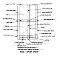
- Figure 4 is a plan view of another embodiment of the present invention illustrating how a sheet of material may be cut and folded into a container according to the present invention.
- This particular embodiment of the present invention utilizes a design whereby the sides defining the top of the box fold inside of the sides defining the bottom of the box when the box is closed. In this design, the pull-tab cord runs through the length of the box.
- Figure 5 is a plan view of yet another embodiment of the present invention illustrating how a sheet of material may be cut and folded into a container according to the present invention.
- This particular embodiment of the present invention utilizes a design whereby the sides defining the top of the box fold inside of the sides defining the bottom of the box when the box is closed.
- the pull-tab cord does not run straight through the length of the box and the side of only one lid is folded to generate the closed box structure.
- Figure 6 is a plan view of yet another embodiment of the present invention illustrating how a sheet of material may be cut and folded into a container according to the present invention.
- This particular embodiment of the present invention utilizes a design whereby the sides defining the top of the box fold inside of the sides defining the bottom of the box when the box is closed.
- a line of perforation is used as a substitute for the pull-tab cord.
- Figure 7 is a plan view of yet another embodiment of the present invention illustrating how a sheet of material may be cut and folded into a container according to the present invention.
- This particular embodiment of the present invention utilizes a design whereby the sides defining the top of the box fold inside of the sides defining the bottom of the box when the box is closed.
- perforations are used in conjunction with the pull-tab cord in order to facilitate separating the box into two portions.
- FIG 8 is a plan view of yet another embodiment of the present invention illustrating how a sheet of material may be cut and folded into a container according to the present invention.
- This particular embodiment of the present invention utilizes a design whereby a cord is utilized with adjacent perforations without means for generating the second, reduced, box structure.
- an opening hole is illustrated in this particular embodiment for finger access to facilitate opening of the closed box structure.
- Figure 9 is a plan view of an example illustrating how a sheet of material may be cut and folded into a container. This particular example utilizes a design wherein the top is removably attached and the bottom portion folds over itself longitudinally to generate the second, reduced, box structure.
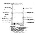
- Figure 10 is a plan view of yet another example illustrating how a sheet of material may be cut and folded into a container.
- This particular example utilizes a design wherein the top is removably attached and the bottom portion folds over itself laterally to generate the second, reduced, box structure.
- a solid line represents a cut.
- a line with large dashes represents folds in the box structure that are most preferably but not necessarily scored using perforations or cuts.
- Lines denoted by small dashes represent lines that are perforated or otherwise weakened so that the consumer may tear the box material along the line.
- Lines denoted by small dots represent latent fold lines along which the box is folded to close the open end of the split box. These lines may be scored using perforations or indentations. Alternatively, they may be left un-scored. Lines denoted by dashes perpendicular to the length of the box represent the location of the cord.
- Figure 1 is a plan view of one preferred embodiment of the present invention and illustrates how a sheet of material may be cut and folded according to the present invention.
- Lower Side Wall A along with Front Bottom Tab A and Back Bottom Tab A are together folded up towards the Bottom.
- Front Bottom Tab A and Back Bottom Tab A are further folded towards the Bottom at an angle of substantially ninety degrees to Lower Side Wall A.
- Lower Side Wall B along with Front Bottom Tab B and Back Bottom Tab B are together folded up towards the Bottom.
- Front Bottom Tab B. and Back Bottom Tab B are further folded towards the Bottom at an angle of substantially ninety degrees to Lower Side Wall B.
- the Lower Front Wall is folded up towards the Bottom and is folded over Front Bottom Tab A and Front Bottom Tab B.
- Upper Side Wall A, Upper Front Wall, and Upper Side Wall B are folded up towards the Top at essentially a ninety-degree angle.
- the Top is folded towards the Bottom using the Back Wall as a hinge.
- Upper Side Wall A, Upper Side Wall B, and the Upper Front Wall fold inside of Lower Side Wall A, Lower Side Wall B, and the Lower Front Wall as the box is closed.
- the consumer grasps the Pull-Tab, and pulls the Cord, thereby ripping or cutting the box along the Cord line.
- the box may then be separated by tearing the box along the perforation parallel to and in line with the cord line in the Lower Front Wall.
- the Cord is extended, and the Pull-Tab is placed on the outer edge of the Lower Front Wall.
- a perforation parallel to and in line with the Cord line is unnecessary.
- both pieces may be disposed of directly, or alternatively, the open end of the large piece may be folded closed, forming a second sturdy container structure (Second Box).
- the open end is folded shut as follows. Removable Section A and Removable Section B are torn out of the box along the perforations.
- the Front Closing Tab and the Rear Closing Tab are folded up towards the Bottom after separating them from the Lower Front Wall and Back Wall along the perforations.
- the open edge of the Top is folded in along Latent Fold Line B.
- the open edge of the Bottom is folded in along Latent Fold Line A white in one embodiment; the Front Closing Tab is inserted between the leaves of the Lower Front Wall.
- the Front Closing Tab is folded inward similar to the Rear Closing Tab.
- the Front Closing Tab and Removable Section A are left connected and both are folded inwards similar to the Rear Closing Tab.
- one edge of the Front Closing Tab is angled in order to facilitate insertion between the leaves of the Lower Front Wall.
- Other embodiments of the present invention may feature a Front Closing Tab without such an angle.
- the reduced size container may now be opened and closed as needed in a manner similar to the original full size container. When closed, the reduced size container is very sturdy and can be used to store leftovers conveniently.
- FIG. 2 is a plan view of another preferred embodiment of the present invention and illustrates how a sheet of material may be cut and folded according to the present invention.
- This particular embodiment is very similar to that illustrated by Example 1 and can be folded into a box structure in the same manner.
- this particular embodiment may be split into two pieces and the open end of the large piece may be folded into a sturdy closed secondary container in a manner similar to that described in Example 1.
- this particular embodiment includes means for holding an additional item within the closed structure of the box such as dipping sauce. Separating the longitudinal edges from Lower Side Wall A and Back Bottom Tab A, then folding in towards the center of the Bottom of the box construct the Sauce Retainer. The additional container can then be placed into the corner of the box and secured by the Sauce Retainer.
- FIG. 3 is a plan view of another preferred embodiment of the present invention and illustrates how a sheet of material may be cut and folded according to the present invention.
- Lower Side Wall A along with Front Bottom Tabs A1, A2, and A3 are together folded up and in towards the Bottom.
- Lower Side Wall B along with Front Bottom Tabs B1, B2, and B3 are together Folded up and in towards the Bottom.
- the Lower Front Wall is attached to Lower Front Tabs A3 and B3. Through this connection, the folding of Upper Side Wall A and Upper Side Wall B pulls the Lower Front Wall up into position. When folded properly, Lower Front Tabs A2 and B2 are folded over 180 degrees towards the Bottom.
- Upper Side Wall A, Upper Side Wall B, and the Upper Front Wall are folded up and in towards the Top into an angle of essentially ninety degrees.
- Upper Rear Tab A and Upper Rear Tab B are further folded in relation to Upper Side Wall A and Upper Side Wall B respectively into an angle of essentially ninety degrees.
- the Top is folded towards the Bottom using the Back Wall as a hinge.
- Upper Side Wall A and Upper Side Wall B fold outside of Lower Side Wall A and Lower Side Wall B, respectively.
- the Upper Front Wall Folds inside of the Lower Front Wall as the box is closed.
- the consumer grasps the Pull-Tab, and pulls the Cord, thereby ripping or cutting the box along the Cord line. The box is then easily separated into two pieces.
- both pieces may be disposed of directly, or alternatively, the open end of the large piece may be folded closed, forming a second sturdy container structure.
- the open end is folded shut as follows.
- the Removable Section is tom out along the perforations and removed from the box structure.
- the Front Closing Tab and the Rear Closing Tab are folded up towards the Top into an angle of essentially ninety degrees after separating them from the Upper Front Wall and Back Wall along the perforations.
- the open edge of the Bottom is folded in along the Lower Latent Fold Line towards the Bottom into an angle of essentially ninety degrees.
- the open edge of the Top is folded in along Latent Fold Line A folding along with it the Front Closing Tab and the Rear Closing Tab.
- the reduced size container may now be opened and closed as needed in a manner similar to the original full size container. When closed, the reduced size container is very sturdy and can be used to store leftovers conveniently.
- FIG. 4 is a plan view of another preferred embodiment of the present invention and illustrates how a sheet of material may be cut and folded according to the present invention.
- This particular embodiment is very similar to that illustrated by Example 1 and can be folded into a box structure in the same manner.
- this particular embodiment may be split into two pieces and the open end of the large piece may be folded into a sturdy closed secondary container in a manner similar to that described in Example 1.
- the cord runs through the length of the box, which may simplify the manufacturing process. Further, in this particular embodiment, once the cord is pulled completely, the first box structure is torn completely in half, which eliminates the additional row of perforations parallel to and at the end of the Cord and the need to tear them. In the most preferable embodiment of this example, perforations are utilized beside the cord on the Lower Front Wall adjacent to Removable Section A in order to reduce the effort required to begin tearing the box.
- FIG. 5 is a plan view of another preferred embodiment of the present invention and illustrates how a sheet of material may be cut and folded according to the present invention.
- This particular embodiment is similar to that illustrated by Example 4 and can be folded into a box structure in the same manner.
- this particular embodiment may be split into two pieces and the open end of the large piece may be folded into a sturdy closed secondary container.
- this particular embodiment utilizes a simplified design in relation to folding the open end shut when compared to that described in Example 4. In order to accomplish this, the cord does not run straight through the length of the box.
- the open end of one of the pieces may be folded shut by folding the open edge of the Top down and inserting Locking Tab A into Slot A.
- FIG. 6 is a plan view of another preferred embodiment of the present invention and illustrates how a sheet of material may be cut and folded according to the present invention.
- This particular embodiment is similar to that illustrated by Examples 1 and can be folded into a box structure in the same manner.
- this particular embodiment may also be split into two pieces and the open end of the large piece may be folded into a sturdy closed secondary container.
- this particular embodiment utilizes perforations instead of the pull-tab cord. Therefore, in order to separate the box into two pieces, the box is torn along the Dividing Perforation.
- Figure 7 is a plan view of another preferred embodiment of the present invention and illustrates how a sheet of material may be cut and folded according to the present invention.
- This particular embodiment is the best mode of the present invention, and is very similar to that illustrated by Example 4 and can be folded into a box structure in the same manner.
- this particular embodiment may be split into two pieces and the open end of the large piece may be forded into a sturdy closed secondary container in a manner similar to that described in Example 1.
- this particular embodiment utilizes perforations adjacent to the Cord in order to reduce the effort required to tear the box material and or facilitate a cleaner tom edge.
- Lines of Perforation extend along both sides of the Cord along essentially the entire length of the box where no other specific type perforation is needed, as illustrated.
- the Line of Perforation extending along the Cord adjacent to the side of the box that is not designed to be folded shut is eliminated.
- the Line of Perforation extending along the Cord adjacent to the side of the box that is designed to be folded shut is eliminated.
- this particular embodiment utilizes an Opening Hole for finger access in order to facilitate opening the closed box structure.
- a portion of the perforation across the front wall adjacent to the Pull-Tab is eliminated. This facilitates removal of Removable Section A along only one row of the perforations across the front wall, which facilitates insertion of the Front Closing Tab between the leaves of the Lower Front Wall.
- FIG 8 is a plan view of another preferred embodiment of the present invention and illustrates how a sheet of material may be cut and folded according to the present invention.
- This particular embodiment is similar to that illustrated by Example 4 and can be folded into a box structure in the same manner.
- this particular embodiment may be split into two pieces in a manner similar to that described in Example 1.
- this embodiment illustrates how the divisional means may be utilized without utilizing the means for folding the open end shut to generate the second box structure. This particular embodiment is particularly advantageous when only disposability is a concern.
- FIG. 9 is a plan view and illustrates how a sheet of material may be cut and folded
- This particular example is similar to that illustrated by Example 4 and can be folded into a box structure in the same manner.
- this particular example utilizes a removably attached Top portion.
- the Top portion is removed.
- the Back Wall Removable Section, the Front wall Removable Section, and one Back. Bottom Tab are removed.
- the Bottom portion is folded over itself longitudinally and shut, generating the second closed box structure.
- FIG 10 is a plan view of another example and illustrates how a sheet of material may be cut and folded .
- This particular example is similar to that illustrated by Example 4 and can be folded into a first box structure in the same manner.
- this particular embodiment utilizes a removably attached Top portion.
- the Top portion is removed.
- the Back Bottom Tabs are removed.
- Side Wall Tab A and Side Wall Tab B are folded in towards the center of the Bottom.
- the Bottom portion is folded over itself laterally with the back wall folding inside of the Lower Front Wall and shut, generating, the second closed box structure.
- the present invention has several key advantages when compared to the prior art.
- the utility of the box as a delivery vehicle is not compromised by the pull-tab cord design because the structural integrity of the box is not weakened until the consumer chooses to pull the tab. Once pulled, the box is easily broken into two conveniently disposable pieces.
- the open end of the split box may be folded shut forming a sturdy storage container.
- the present invention achieves its utility while retaining a simple design that is easy to use and economical to manufacture.
Landscapes
- Engineering & Computer Science (AREA)
- Mechanical Engineering (AREA)
- Cartons (AREA)
Claims (12)
- Wiederverschließbarer Behälter mita. einem Bodenabschnitt, dessen Umfang bestimmt ist durch gelenkig oder schwenkbar befestigte, gegenüberliegende untere Seitenwände, einer gelenkig oder schwenkbar befestigten Rückwand und einer gelenkigen oder schwenkbar befestigten Vorderwandb. einem oberen Abschnitt, der gelenkig oder schwenkbar an der Rückwand befestigt ist, wobei der Umfang des oberen Abschnitts definiert ist durch gelenkig oder schwenkbar befestigte, gegenüberliegende obere Seitenwände, einer gelenkig oder schwenkbar befestigten oberen Vorderwand und der gelenkig oder schwenkbar befestigten Rückwandc. Teilungsmitteln zur Erleichterung der Aufteilung des Behälters in wenigstens zwei Stücke, die in Längsrichtung durch den oberen Abschnitt und den Bodenabschnitt des Behälters angeordnet sind, und
gekennzeichnet durch die Bereitstellung vond. einem lösbaren Abschnitt an der oberen Vorderwand benachbart zu den Teilungsmitteln und definiert auf zwei Seiten durch Perforationen und auf der dritten Seite durch die Teilungsmittele. einem Laschenabschnitt auf der Rückwand benachbart zu den Teilungsmitteln, der auf zwei Seiten durch Perforationen, auf der dritten Seite durch die Trennmittel definiert ist und gelenkig oder schwenkbar an dem Bodenabschnitt auf der vierten Seite befestigt istf. einem lösbaren Abschnitt an der unteren Vorderwand, der zu den Teilungsmitteln benachbart ist und an zwei Seiten durch Perforationen und an der dritten Seite durch die Teilungsmittel definiert ist. - Behälter nach Anspruch 1, wobei die Teilungsmittel eine Schnur aufweisen.
- Behälter nach Anspruch 1, wobei die Teilungsmittel Perforationen aufweisen.
- Behälter nach Anspruch 1, wobei die unteren Seitenwände gelenkig oder schwenkbar befestigte Laschen benachbart zur Vorderwand und benachbart zur Rückwand umfassen.
- Behälter nach Anspruch 1, wobei die untere Vorderwand über sich selbst gefaltet ist, wobei sie eine doppelwandige Struktur bildet.
- Behälter nach Anspruch 1, wobei er ferner einen Laschenabschnitt an der unteren Vorderwand aufweist, der benachbart zu den Teilungsmitteln ist und auf zwei Seiten durch Perforationen und auf der dritten Seite durch die Teilungsmittel definiert ist und gelenkig oder schwenkbar am Bodenabschnitt befestigt ist.
- Behälter nach Anspruch 1, wobei er ferner einen Halterungs- oder Aufnahmeabschnitt aufweist, der durch Perforationen an der unteren Seitenwand und einem Laschenabschnitt über eine Ecke des gefalteten Behälters definiert ist und gelenkig oder schwenkbar an der unteren Seitenwand an der dritten Seite befestigt ist und dem Laschenabschnitt an der vierten Seite.
- Behälter nach Anspruch 1, wobei die Teilungsmittel aufweisena. eine Schnurb. eine Zuglasche, die der Schnur zugeordnet ist.
- Behälter nach Anspruch 1, wobei die Teilungsmittel mehrfache im Wesentlichen parallel zueinander angeordnete Reihen von Perforationen aufweisen.
- Behälter nach Anspruch 8, wobei er ferner eine Reihe von Perforationen aufweist, die benachbart und im Wesentlichen parallel mit einer Seite der Schnur angeordnet ist.
- Behälter nach Anspruch 10, wobei jede Perforation der Reihe von Perforationen aufweist,a. zwei längliche Schnitte, die im Wesentlichen unter 90 Grad zueinander liegen und in unmittelbarer Nähe zueinander angeordnet sind, um im Wesentlichen eine einzelne Perforation zu erzeugenb. wobei die länglichen Schnitte so angeordnet sind, dass einer im Wesentlichen parallel zur Schnur und der andere im Wesentlichen im rechten Winkel zur Schnur liegt.
- Behälter nach Anspruch 1, wobei die innere Oberfläche der Boxstruktur mit einer wasserdichten oder wasserundurchlässigen Substanz beschichtet ist.
Priority Applications (1)
| Application Number | Priority Date | Filing Date | Title |
|---|---|---|---|
| EP12169848.4A EP2495182B1 (de) | 2006-06-19 | 2007-06-18 | Einfach entsorgbarer, modularer Behälter für Pizza und dergleichen |
Applications Claiming Priority (3)
| Application Number | Priority Date | Filing Date | Title |
|---|---|---|---|
| US81492406P | 2006-06-19 | 2006-06-19 | |
| US85933106P | 2006-11-15 | 2006-11-15 | |
| PCT/US2007/014287 WO2007149441A2 (en) | 2006-06-19 | 2007-06-18 | Easily disposable modular container for pizza and the like |
Related Child Applications (2)
| Application Number | Title | Priority Date | Filing Date |
|---|---|---|---|
| EP12169848.4A Division-Into EP2495182B1 (de) | 2006-06-19 | 2007-06-18 | Einfach entsorgbarer, modularer Behälter für Pizza und dergleichen |
| EP12169848.4A Division EP2495182B1 (de) | 2006-06-19 | 2007-06-18 | Einfach entsorgbarer, modularer Behälter für Pizza und dergleichen |
Publications (3)
| Publication Number | Publication Date |
|---|---|
| EP2094572A2 EP2094572A2 (de) | 2009-09-02 |
| EP2094572A4 EP2094572A4 (de) | 2010-07-14 |
| EP2094572B1 true EP2094572B1 (de) | 2012-08-29 |
Family
ID=38834073
Family Applications (2)
| Application Number | Title | Priority Date | Filing Date |
|---|---|---|---|
| EP07809674A Active EP2094572B1 (de) | 2006-06-19 | 2007-06-18 | Einfach entsorgbarer modularer behälter für pizza und dergleichen |
| EP12169848.4A Not-in-force EP2495182B1 (de) | 2006-06-19 | 2007-06-18 | Einfach entsorgbarer, modularer Behälter für Pizza und dergleichen |
Family Applications After (1)
| Application Number | Title | Priority Date | Filing Date |
|---|---|---|---|
| EP12169848.4A Not-in-force EP2495182B1 (de) | 2006-06-19 | 2007-06-18 | Einfach entsorgbarer, modularer Behälter für Pizza und dergleichen |
Country Status (6)
| Country | Link |
|---|---|
| US (1) | US20080006679A1 (de) |
| EP (2) | EP2094572B1 (de) |
| CA (1) | CA2707462A1 (de) |
| ES (1) | ES2391840T3 (de) |
| PT (1) | PT2094572E (de) |
| WO (1) | WO2007149441A2 (de) |
Families Citing this family (10)
| Publication number | Priority date | Publication date | Assignee | Title |
|---|---|---|---|---|
| AU2009100873B4 (en) * | 2009-09-01 | 2010-10-14 | Aaron Grant Hatton | Serving and storage container |
| US9233515B2 (en) * | 2013-05-10 | 2016-01-12 | Lbp Manufacturing Llc | Clamshell carton with tear strip |
| US8919635B1 (en) | 2014-01-28 | 2014-12-30 | John J. Biagioni | Blank for collapsible folded container |
| US20170202401A1 (en) * | 2015-10-22 | 2017-07-20 | David Mortell | Hot Pizza Box |
| EP3530583B1 (de) | 2018-02-27 | 2021-01-20 | Antonio Malandrini | Zuschnitt einer komprimierbaren faltschachtel und komprimierbare faltschachtel |
| US10793314B2 (en) | 2018-06-11 | 2020-10-06 | Darian Straszewski | Foldable pizza box and method |
| USD878200S1 (en) | 2018-10-23 | 2020-03-17 | DaVinci Box Company, LLC | Reusable box blank |
| USD914496S1 (en) | 2018-10-23 | 2021-03-30 | Davinci Sox Company, Llc | Reusable box blank |
| USD926567S1 (en) | 2018-11-13 | 2021-08-03 | Darian Straszewski | Foldable pizza box |
| USD926566S1 (en) | 2018-11-13 | 2021-08-03 | Darian Straszewski | Foldable pizza box |
Family Cites Families (37)
| Publication number | Priority date | Publication date | Assignee | Title |
|---|---|---|---|---|
| US1288132A (en) * | 1918-05-01 | 1918-12-17 | Cedaroid Co Inc | Cardboard receptacle and method of forming the same. |
| US1652746A (en) * | 1924-04-26 | 1927-12-13 | Terwilliger William Gilbert | Carton |
| US2985075A (en) * | 1956-02-20 | 1961-05-23 | Knutsson-Hall Folke Knut | Method of manufacturing boxes of cardboard |
| US2967010A (en) * | 1958-03-21 | 1961-01-03 | Kimberly Clark Co | Cellulosic product |
| US3094267A (en) * | 1960-09-28 | 1963-06-18 | Alton Box Board Co | End cushioned paperboard container |
| US3167240A (en) * | 1963-11-05 | 1965-01-26 | Container Corp | Reduceable carton with reclosure feature |
| US3302855A (en) * | 1964-08-18 | 1967-02-07 | Reynolds Metals Co | Reducible container construction and blanks therefor or the like |
| US3285496A (en) * | 1965-01-13 | 1966-11-15 | Barnhardt Mfg Co | Polygonal tubular container with reclosable end |
| US3465946A (en) * | 1967-10-26 | 1969-09-09 | Hoerner Waldorf Corp | Recessed end containers |
| US4111306A (en) * | 1977-05-18 | 1978-09-05 | Champion International Corporation | Self-contained baking tray carton |
| US4237171A (en) * | 1979-02-21 | 1980-12-02 | Fred C. Laage | Insulated and moisture absorbent food container and method of manufacture |
| US4502514A (en) * | 1983-07-18 | 1985-03-05 | International Business Machines Corporation | Toner cartridge and method of replenishing toner to a xerographic device |
| US4621736A (en) * | 1984-04-23 | 1986-11-11 | Waldorf Corporation | Recloseable carton |
| US5098757A (en) * | 1987-02-11 | 1992-03-24 | H.B. Fuller Company | Tear tape opening system |
| US5135790A (en) * | 1987-02-11 | 1992-08-04 | H. B. Fuller Company | Tear tape opening system |
| US5071062A (en) * | 1991-01-28 | 1991-12-10 | Bradley David E | Reducible carton for pizza pies and the like |
| US5110038A (en) * | 1991-04-16 | 1992-05-05 | Frank Pantisano | Plate forming and break down pizza box |
| US5305949A (en) | 1991-12-24 | 1994-04-26 | Linden Gerald E | Foldable, easily-disposable pizza box, and methods of making and using same |
| US5273206A (en) | 1992-07-21 | 1993-12-28 | Wtpa, Incorporated | Disposable box by destructive folding |
| US5197659A (en) | 1992-07-21 | 1993-03-30 | Wtpa, Incorporated | Disposable box by folding into a log-shaped configuration |
| US5209392A (en) | 1992-08-19 | 1993-05-11 | Walter Anatro | Recyclable pizza box |
| US5375761A (en) * | 1993-01-22 | 1994-12-27 | Sullivan; Laura C. | Pizza box and method of disposing of used pizza boxes |
| US5811957A (en) | 1995-12-21 | 1998-09-22 | General Motors Corporation | Speed sensorless hybrid vector controlled induction motor with zero speed operation |
| US5702054A (en) | 1996-05-23 | 1997-12-30 | Weyerhaeuser Company | Single piece food package |
| US5836451A (en) * | 1997-09-11 | 1998-11-17 | Mebane Packaging Corporation | Carton having tray and return carton |
| US6109512A (en) * | 1998-08-31 | 2000-08-29 | Jefferson Smurfit Corporation | Angled front lock system for handled pizza carton |
| US6375066B1 (en) | 2000-03-01 | 2002-04-23 | Weyerhaeuser Company | Reducible carton for pizza pies and the like |
| US6336584B1 (en) * | 2000-07-07 | 2002-01-08 | Roch Francois | Multiple use carton box |
| US6440050B1 (en) * | 2000-09-19 | 2002-08-27 | Patsy R. Capparelli | Method of forming a variable sized and shaped pizza box and apparatus thereof |
| US6547125B2 (en) * | 2001-09-10 | 2003-04-15 | John D. Correll | Material-saving food carton |
| US7051919B1 (en) | 2003-08-22 | 2006-05-30 | Walsh William R | Convertible pizza box |
| US20050150938A1 (en) * | 2004-01-09 | 2005-07-14 | Correll John D. | Uniquely-disposed cup-holder strap |
| US7373765B2 (en) * | 2004-02-26 | 2008-05-20 | Kimberly-Clark Worldwide, Inc. | Shipping carton with pull tabs and tear strip |
| GB0409248D0 (en) * | 2004-04-26 | 2004-05-26 | Encase Ltd | A folded article |
| US20060054676A1 (en) * | 2004-08-13 | 2006-03-16 | Wischusen Henry Iii | Easy open container |
| US20060255106A1 (en) * | 2005-05-12 | 2006-11-16 | Graphic Packaging International, Inc. | Variable volume carton |
| US20070267471A1 (en) * | 2006-05-18 | 2007-11-22 | Falana Robert J | Foldable pizza box |
-
2007
- 2007-06-18 PT PT07809674T patent/PT2094572E/pt unknown
- 2007-06-18 EP EP07809674A patent/EP2094572B1/de active Active
- 2007-06-18 WO PCT/US2007/014287 patent/WO2007149441A2/en not_active Ceased
- 2007-06-18 CA CA2707462A patent/CA2707462A1/en active Pending
- 2007-06-18 ES ES07809674T patent/ES2391840T3/es active Active
- 2007-06-18 EP EP12169848.4A patent/EP2495182B1/de not_active Not-in-force
- 2007-06-19 US US11/820,330 patent/US20080006679A1/en not_active Abandoned
Also Published As
| Publication number | Publication date |
|---|---|
| PT2094572E (pt) | 2012-11-26 |
| WO2007149441A3 (en) | 2008-05-02 |
| ES2391840T3 (es) | 2012-11-30 |
| WO2007149441A2 (en) | 2007-12-27 |
| EP2495182A1 (de) | 2012-09-05 |
| CA2707462A1 (en) | 2007-12-27 |
| US20080006679A1 (en) | 2008-01-10 |
| EP2094572A2 (de) | 2009-09-02 |
| EP2495182B1 (de) | 2014-06-11 |
| EP2094572A4 (de) | 2010-07-14 |
Similar Documents
| Publication | Publication Date | Title |
|---|---|---|
| EP2094572B1 (de) | Einfach entsorgbarer modularer behälter für pizza und dergleichen | |
| US8393529B2 (en) | EZ-fold modular pizza box | |
| US7699214B2 (en) | Carton with recloseable lid | |
| US20030230504A1 (en) | Dispensing container and method for manufacturing same | |
| US6945449B2 (en) | Package design and method of forming a package | |
| CA2100963A1 (en) | Reducible carton for pizza pies and the like | |
| KR20120103706A (ko) | 덮여진 부착탭을 갖춘 용기 | |
| US5325989A (en) | Box and blank for packaging powdered soap or the like | |
| US5251819A (en) | Collapsible container for ease of disposal | |
| US11472597B1 (en) | Separable multi-compartment container | |
| US5188223A (en) | Folding box | |
| US5012930A (en) | One-piece, self-locking computer software container | |
| US20140191022A1 (en) | Method of Using Modular Pizza Box | |
| US5377905A (en) | Packaging box, blank therefor, and method of assembly | |
| EP3313754B1 (de) | Behälter für konsumgüter mit gleitendem teil | |
| EP3530585A1 (de) | Beutel und verfahren zur herstellung eines beutels | |
| EP1669306B1 (de) | Behälter mit seitlicher Öffnung und akustischer Anzeige der Öffnung | |
| WO2013129981A1 (en) | Container comprising tear tape, a container blank, and a method for opening said container | |
| US20250296726A1 (en) | Carton With Insert | |
| WO2013170978A1 (en) | Re-closable inner package with nesting flaps | |
| CA1045598A (en) | Twin perforated edge opening | |
| EP2125540A1 (de) | Packung zur aufnahme eines tabakprodukts | |
| EP3844074B1 (de) | Wiederverschliessbarer karton und zuschnitt dafür | |
| GB2073707A (en) | Carton with reclosable end structure | |
| AU2005101025A4 (en) | Tearable Sheet Including a Perforated Tear Line |
Legal Events
| Date | Code | Title | Description |
|---|---|---|---|
| PUAI | Public reference made under article 153(3) epc to a published international application that has entered the european phase |
Free format text: ORIGINAL CODE: 0009012 |
|
| 17P | Request for examination filed |
Effective date: 20090122 |
|
| AK | Designated contracting states |
Kind code of ref document: A2 Designated state(s): AT BE BG CH CY CZ DE DK EE ES FI FR GB GR HU IE IS IT LI LT LU LV MC MT NL PL PT RO SE SI SK TR |
|
| AX | Request for extension of the european patent |
Extension state: AL BA HR MK RS |
|
| DAX | Request for extension of the european patent (deleted) | ||
| A4 | Supplementary search report drawn up and despatched |
Effective date: 20100616 |
|
| 17Q | First examination report despatched |
Effective date: 20110211 |
|
| GRAP | Despatch of communication of intention to grant a patent |
Free format text: ORIGINAL CODE: EPIDOSNIGR1 |
|
| GRAS | Grant fee paid |
Free format text: ORIGINAL CODE: EPIDOSNIGR3 |
|
| RAP1 | Party data changed (applicant data changed or rights of an application transferred) |
Owner name: WARE, BRADY NEAL Owner name: VOLZ, WILLIAM |
|
| RIN1 | Information on inventor provided before grant (corrected) |
Inventor name: VOLZ, WILLIAM Inventor name: WARE, BRADY NEAL |
|
| GRAA | (expected) grant |
Free format text: ORIGINAL CODE: 0009210 |
|
| AK | Designated contracting states |
Kind code of ref document: B1 Designated state(s): AT BE BG CH CY CZ DE DK EE ES FI FR GB GR HU IE IS IT LI LT LU LV MC MT NL PL PT RO SE SI SK TR |
|
| REG | Reference to a national code |
Ref country code: GB Ref legal event code: FG4D |
|
| REG | Reference to a national code |
Ref country code: CH Ref legal event code: EP |
|
| REG | Reference to a national code |
Ref country code: AT Ref legal event code: REF Ref document number: 572925 Country of ref document: AT Kind code of ref document: T Effective date: 20120915 |
|
| REG | Reference to a national code |
Ref country code: IE Ref legal event code: FG4D |
|
| REG | Reference to a national code |
Ref country code: DE Ref legal event code: R096 Ref document number: 602007025155 Country of ref document: DE Effective date: 20121025 |
|
| REG | Reference to a national code |
Ref country code: CH Ref legal event code: NV Representative=s name: ISLER & PEDRAZZINI AG |
|
| REG | Reference to a national code |
Ref country code: PT Ref legal event code: SC4A Free format text: AVAILABILITY OF NATIONAL TRANSLATION Effective date: 20121112 |
|
| REG | Reference to a national code |
Ref country code: ES Ref legal event code: FG2A Ref document number: 2391840 Country of ref document: ES Kind code of ref document: T3 Effective date: 20121130 |
|
| REG | Reference to a national code |
Ref country code: AT Ref legal event code: MK05 Ref document number: 572925 Country of ref document: AT Kind code of ref document: T Effective date: 20120829 |
|
| REG | Reference to a national code |
Ref country code: NL Ref legal event code: VDEP Effective date: 20120829 |
|
| REG | Reference to a national code |
Ref country code: LT Ref legal event code: MG4D Effective date: 20120829 |
|
| PG25 | Lapsed in a contracting state [announced via postgrant information from national office to epo] |
Ref country code: IS Free format text: LAPSE BECAUSE OF FAILURE TO SUBMIT A TRANSLATION OF THE DESCRIPTION OR TO PAY THE FEE WITHIN THE PRESCRIBED TIME-LIMIT Effective date: 20121229 Ref country code: CY Free format text: LAPSE BECAUSE OF FAILURE TO SUBMIT A TRANSLATION OF THE DESCRIPTION OR TO PAY THE FEE WITHIN THE PRESCRIBED TIME-LIMIT Effective date: 20120829 Ref country code: FI Free format text: LAPSE BECAUSE OF FAILURE TO SUBMIT A TRANSLATION OF THE DESCRIPTION OR TO PAY THE FEE WITHIN THE PRESCRIBED TIME-LIMIT Effective date: 20120829 Ref country code: AT Free format text: LAPSE BECAUSE OF FAILURE TO SUBMIT A TRANSLATION OF THE DESCRIPTION OR TO PAY THE FEE WITHIN THE PRESCRIBED TIME-LIMIT Effective date: 20120829 Ref country code: LT Free format text: LAPSE BECAUSE OF FAILURE TO SUBMIT A TRANSLATION OF THE DESCRIPTION OR TO PAY THE FEE WITHIN THE PRESCRIBED TIME-LIMIT Effective date: 20120829 |
|
| PG25 | Lapsed in a contracting state [announced via postgrant information from national office to epo] |
Ref country code: GR Free format text: LAPSE BECAUSE OF FAILURE TO SUBMIT A TRANSLATION OF THE DESCRIPTION OR TO PAY THE FEE WITHIN THE PRESCRIBED TIME-LIMIT Effective date: 20121130 Ref country code: LV Free format text: LAPSE BECAUSE OF FAILURE TO SUBMIT A TRANSLATION OF THE DESCRIPTION OR TO PAY THE FEE WITHIN THE PRESCRIBED TIME-LIMIT Effective date: 20120829 Ref country code: SI Free format text: LAPSE BECAUSE OF FAILURE TO SUBMIT A TRANSLATION OF THE DESCRIPTION OR TO PAY THE FEE WITHIN THE PRESCRIBED TIME-LIMIT Effective date: 20120829 Ref country code: SE Free format text: LAPSE BECAUSE OF FAILURE TO SUBMIT A TRANSLATION OF THE DESCRIPTION OR TO PAY THE FEE WITHIN THE PRESCRIBED TIME-LIMIT Effective date: 20120829 Ref country code: BE Free format text: LAPSE BECAUSE OF FAILURE TO SUBMIT A TRANSLATION OF THE DESCRIPTION OR TO PAY THE FEE WITHIN THE PRESCRIBED TIME-LIMIT Effective date: 20120829 |
|
| PG25 | Lapsed in a contracting state [announced via postgrant information from national office to epo] |
Ref country code: EE Free format text: LAPSE BECAUSE OF FAILURE TO SUBMIT A TRANSLATION OF THE DESCRIPTION OR TO PAY THE FEE WITHIN THE PRESCRIBED TIME-LIMIT Effective date: 20120829 Ref country code: NL Free format text: LAPSE BECAUSE OF FAILURE TO SUBMIT A TRANSLATION OF THE DESCRIPTION OR TO PAY THE FEE WITHIN THE PRESCRIBED TIME-LIMIT Effective date: 20120829 Ref country code: RO Free format text: LAPSE BECAUSE OF FAILURE TO SUBMIT A TRANSLATION OF THE DESCRIPTION OR TO PAY THE FEE WITHIN THE PRESCRIBED TIME-LIMIT Effective date: 20120829 Ref country code: CZ Free format text: LAPSE BECAUSE OF FAILURE TO SUBMIT A TRANSLATION OF THE DESCRIPTION OR TO PAY THE FEE WITHIN THE PRESCRIBED TIME-LIMIT Effective date: 20120829 Ref country code: DK Free format text: LAPSE BECAUSE OF FAILURE TO SUBMIT A TRANSLATION OF THE DESCRIPTION OR TO PAY THE FEE WITHIN THE PRESCRIBED TIME-LIMIT Effective date: 20120829 |
|
| PG25 | Lapsed in a contracting state [announced via postgrant information from national office to epo] |
Ref country code: SK Free format text: LAPSE BECAUSE OF FAILURE TO SUBMIT A TRANSLATION OF THE DESCRIPTION OR TO PAY THE FEE WITHIN THE PRESCRIBED TIME-LIMIT Effective date: 20120829 Ref country code: PL Free format text: LAPSE BECAUSE OF FAILURE TO SUBMIT A TRANSLATION OF THE DESCRIPTION OR TO PAY THE FEE WITHIN THE PRESCRIBED TIME-LIMIT Effective date: 20120829 |
|
| PLBE | No opposition filed within time limit |
Free format text: ORIGINAL CODE: 0009261 |
|
| STAA | Information on the status of an ep patent application or granted ep patent |
Free format text: STATUS: NO OPPOSITION FILED WITHIN TIME LIMIT |
|
| PG25 | Lapsed in a contracting state [announced via postgrant information from national office to epo] |
Ref country code: BG Free format text: LAPSE BECAUSE OF FAILURE TO SUBMIT A TRANSLATION OF THE DESCRIPTION OR TO PAY THE FEE WITHIN THE PRESCRIBED TIME-LIMIT Effective date: 20121129 |
|
| PGFP | Annual fee paid to national office [announced via postgrant information from national office to epo] |
Ref country code: CH Payment date: 20130613 Year of fee payment: 7 |
|
| 26N | No opposition filed |
Effective date: 20130530 |
|
| PGFP | Annual fee paid to national office [announced via postgrant information from national office to epo] |
Ref country code: PT Payment date: 20130612 Year of fee payment: 7 |
|
| REG | Reference to a national code |
Ref country code: DE Ref legal event code: R097 Ref document number: 602007025155 Country of ref document: DE Effective date: 20130530 |
|
| PG25 | Lapsed in a contracting state [announced via postgrant information from national office to epo] |
Ref country code: MC Free format text: LAPSE BECAUSE OF FAILURE TO SUBMIT A TRANSLATION OF THE DESCRIPTION OR TO PAY THE FEE WITHIN THE PRESCRIBED TIME-LIMIT Effective date: 20120829 |
|
| REG | Reference to a national code |
Ref country code: PT Ref legal event code: MM4A Free format text: LAPSE DUE TO NON-PAYMENT OF FEES Effective date: 20141218 |
|
| PG25 | Lapsed in a contracting state [announced via postgrant information from national office to epo] |
Ref country code: PT Free format text: LAPSE BECAUSE OF NON-PAYMENT OF DUE FEES Effective date: 20141218 |
|
| REG | Reference to a national code |
Ref country code: CH Ref legal event code: PL |
|
| PG25 | Lapsed in a contracting state [announced via postgrant information from national office to epo] |
Ref country code: MT Free format text: LAPSE BECAUSE OF FAILURE TO SUBMIT A TRANSLATION OF THE DESCRIPTION OR TO PAY THE FEE WITHIN THE PRESCRIBED TIME-LIMIT Effective date: 20120829 |
|
| PG25 | Lapsed in a contracting state [announced via postgrant information from national office to epo] |
Ref country code: LI Free format text: LAPSE BECAUSE OF NON-PAYMENT OF DUE FEES Effective date: 20140630 Ref country code: CH Free format text: LAPSE BECAUSE OF NON-PAYMENT OF DUE FEES Effective date: 20140630 |
|
| PG25 | Lapsed in a contracting state [announced via postgrant information from national office to epo] |
Ref country code: TR Free format text: LAPSE BECAUSE OF FAILURE TO SUBMIT A TRANSLATION OF THE DESCRIPTION OR TO PAY THE FEE WITHIN THE PRESCRIBED TIME-LIMIT Effective date: 20120829 |
|
| PG25 | Lapsed in a contracting state [announced via postgrant information from national office to epo] |
Ref country code: HU Free format text: LAPSE BECAUSE OF FAILURE TO SUBMIT A TRANSLATION OF THE DESCRIPTION OR TO PAY THE FEE WITHIN THE PRESCRIBED TIME-LIMIT; INVALID AB INITIO Effective date: 20070618 Ref country code: LU Free format text: LAPSE BECAUSE OF NON-PAYMENT OF DUE FEES Effective date: 20130618 |
|
| REG | Reference to a national code |
Ref country code: FR Ref legal event code: PLFP Year of fee payment: 10 |
|
| REG | Reference to a national code |
Ref country code: FR Ref legal event code: PLFP Year of fee payment: 11 |
|
| REG | Reference to a national code |
Ref country code: FR Ref legal event code: PLFP Year of fee payment: 12 |
|
| PGFP | Annual fee paid to national office [announced via postgrant information from national office to epo] |
Ref country code: GB Payment date: 20250618 Year of fee payment: 19 |
|
| PGFP | Annual fee paid to national office [announced via postgrant information from national office to epo] |
Ref country code: FR Payment date: 20250630 Year of fee payment: 19 |
|
| PGFP | Annual fee paid to national office [announced via postgrant information from national office to epo] |
Ref country code: IE Payment date: 20250618 Year of fee payment: 19 |
|
| PGFP | Annual fee paid to national office [announced via postgrant information from national office to epo] |
Ref country code: ES Payment date: 20250702 Year of fee payment: 19 |
|
| PGFP | Annual fee paid to national office [announced via postgrant information from national office to epo] |
Ref country code: DE Payment date: 20250626 Year of fee payment: 19 |
|
| PGFP | Annual fee paid to national office [announced via postgrant information from national office to epo] |
Ref country code: IT Payment date: 20250620 Year of fee payment: 19 |