EP2094350B1 - Grouped leads for spinal stimulation - Google Patents
Grouped leads for spinal stimulation Download PDFInfo
- Publication number
- EP2094350B1 EP2094350B1 EP07865338.3A EP07865338A EP2094350B1 EP 2094350 B1 EP2094350 B1 EP 2094350B1 EP 07865338 A EP07865338 A EP 07865338A EP 2094350 B1 EP2094350 B1 EP 2094350B1
- Authority
- EP
- European Patent Office
- Prior art keywords
- electrodes
- dorsal root
- electrode
- root ganglion
- stimulation
- Prior art date
- Legal status (The legal status is an assumption and is not a legal conclusion. Google has not performed a legal analysis and makes no representation as to the accuracy of the status listed.)
- Not-in-force
Links
- 230000000638 stimulation Effects 0.000 title claims description 50
- 210000003594 spinal ganglia Anatomy 0.000 claims description 58
- 230000004936 stimulating effect Effects 0.000 claims description 10
- 210000003484 anatomy Anatomy 0.000 claims description 8
- 210000000278 spinal cord Anatomy 0.000 description 29
- 210000001519 tissue Anatomy 0.000 description 18
- 210000005036 nerve Anatomy 0.000 description 10
- 238000000034 method Methods 0.000 description 9
- 208000002193 Pain Diseases 0.000 description 8
- 230000036407 pain Effects 0.000 description 8
- 210000000273 spinal nerve root Anatomy 0.000 description 7
- 208000035824 paresthesia Diseases 0.000 description 4
- 210000000988 bone and bone Anatomy 0.000 description 3
- 238000002513 implantation Methods 0.000 description 3
- 210000004126 nerve fiber Anatomy 0.000 description 3
- 238000011282 treatment Methods 0.000 description 3
- 241001269524 Dura Species 0.000 description 2
- 210000001175 cerebrospinal fluid Anatomy 0.000 description 2
- 230000002939 deleterious effect Effects 0.000 description 2
- 239000000835 fiber Substances 0.000 description 2
- 239000012530 fluid Substances 0.000 description 2
- 230000001537 neural effect Effects 0.000 description 2
- 230000037361 pathway Effects 0.000 description 2
- 230000001953 sensory effect Effects 0.000 description 2
- 230000005641 tunneling Effects 0.000 description 2
- 206010001497 Agitation Diseases 0.000 description 1
- 208000008035 Back Pain Diseases 0.000 description 1
- 208000003098 Ganglion Cysts Diseases 0.000 description 1
- 206010033425 Pain in extremity Diseases 0.000 description 1
- 208000005400 Synovial Cyst Diseases 0.000 description 1
- 238000004873 anchoring Methods 0.000 description 1
- 238000013459 approach Methods 0.000 description 1
- 238000003491 array Methods 0.000 description 1
- 230000001174 ascending effect Effects 0.000 description 1
- 210000001217 buttock Anatomy 0.000 description 1
- 230000001419 dependent effect Effects 0.000 description 1
- 230000000694 effects Effects 0.000 description 1
- 230000005684 electric field Effects 0.000 description 1
- 229920005570 flexible polymer Polymers 0.000 description 1
- 238000002594 fluoroscopy Methods 0.000 description 1
- 239000007943 implant Substances 0.000 description 1
- 230000001788 irregular Effects 0.000 description 1
- 238000002690 local anesthesia Methods 0.000 description 1
- 230000000873 masking effect Effects 0.000 description 1
- 239000000463 material Substances 0.000 description 1
- 230000005012 migration Effects 0.000 description 1
- 238000013508 migration Methods 0.000 description 1
- 238000012986 modification Methods 0.000 description 1
- 230000004048 modification Effects 0.000 description 1
- 210000003205 muscle Anatomy 0.000 description 1
- 210000000944 nerve tissue Anatomy 0.000 description 1
- 210000000118 neural pathway Anatomy 0.000 description 1
- 230000010004 neural pathway Effects 0.000 description 1
- 231100000862 numbness Toxicity 0.000 description 1
- 210000000578 peripheral nerve Anatomy 0.000 description 1
- 210000003446 pia mater Anatomy 0.000 description 1
- 238000011084 recovery Methods 0.000 description 1
- 230000035807 sensation Effects 0.000 description 1
- 229920002379 silicone rubber Polymers 0.000 description 1
- 208000024891 symptom Diseases 0.000 description 1
- 230000001225 therapeutic effect Effects 0.000 description 1
Images


Classifications
-
- A—HUMAN NECESSITIES
- A61—MEDICAL OR VETERINARY SCIENCE; HYGIENE
- A61N—ELECTROTHERAPY; MAGNETOTHERAPY; RADIATION THERAPY; ULTRASOUND THERAPY
- A61N1/00—Electrotherapy; Circuits therefor
- A61N1/02—Details
- A61N1/04—Electrodes
- A61N1/05—Electrodes for implantation or insertion into the body, e.g. heart electrode
- A61N1/0551—Spinal or peripheral nerve electrodes
- A61N1/0553—Paddle shaped electrodes, e.g. for laminotomy
Definitions
- spinal cord stimulation spinal cord stimulation
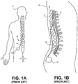
- Figs. 1A-1B illustrate conventional placement of an SCS system 10.
- Conventional SCS systems include an implantable power source or implantable pulse generator (IPG) 12 and an implantable lead 14.
- IPGs 12 are similar in size and weight to pacemakers and are typically implanted in the buttocks of a patient P.
- the lead 14 is implanted into the epidural space E of the spinal column and positioned against the dura layer D of the spinal cord S, as illustrated in Fig. 1B .
- the lead 14 is implanted either through the skin via an epidural needle (for percutaneous leads) or directly and surgically through a mini laminotomy operation (for paddle leads).
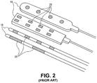
- Fig. 2 illustrates example conventional paddle leads 16 and percutaneous leads 18.
- Paddle leads 16 typically have the form of a slab of silicon rubber having one or more electrodes 20 on its surface.
- Example dimensions of a paddle lead 16 is illustrated in Fig. 3 .
- Percutaneous leads 18 typically have the form of a tube or rod having one or more electrodes 20 extending therearound.
- Example dimensions of a percutaneous lead 18 is illustrated in Fig. 4 .
- Implantation of a percutaneous lead 18 typically involves an incision over the low back area (for control of back and leg pain) or over the upper back and neck area (for pain in the arms).
- An epidural needle is placed through the incision into the epidural space and the lead is advanced and steered over the spinal cord until it reaches the area of the spinal cord that, when electrically stimulated, produces a comfortable tingling sensation (paresthesia) that covers the patient's painful area.
- the lead is moved and turned on and off while the patient provides feedback about stimulation coverage. Because the patient participates in this operation and directs the operator to the correct area of the spinal cord, the procedure is performed with local anesthesia.
- Implantation of paddle leads 16 typically involves performing a mini laminotomy to implant the lead. An incision is made either slightly below or above the spinal cord segment to be stimulated. The epidural space is entered directly through the hole in the bone and a paddle lead 16 is placed over the area to stimulate the spinal cord. The target area for stimulation usually has been located before this procedure during a spinal cord stimulation trial with percutaneous leads 18.
- the lead 14 is positioned upon the spinal cord dura layer D so that the electrodes 20 stimulate a wide portion of the spinal cord and associated spinal nervous tissue.
- the spinal cord is a continuous body and three spinal levels of the spinal cord are illustrated.
- spinal levels are sub-sections of the spinal cord S depicting that portion where the dorsal root DR and ventral root VR join the spinal cord S.
- the peripheral nerve N divides into the dorsal root DR and the dorsal root ganglion DRG and the ventral nerve root VR each of which feed into the spinal cord S.
- An ascending pathway 17 is illustrated between level 2 and level 1 and a descending pathway 19 is illustrated from level 2 to level 3.
- Spinal levels can correspond to the veterbral levels of the spine commonly used to describe the vertebral bodies of the spine. For simplicity, each level illustrates the nerves of only one side and a normal anatomical configuration would have similar nerves illustrated in the side of the spinal cord directly adjacent the lead.
- non-specific stimulation refers to the fact that the stimulation energy is provided to all spinal levels including the nerves and the spinal cord generally and indiscriminately. Even if the epidural electrode is reduced in size to simply stimulate only one level, that electrode will apply stimulation energy indiscriminately to everything (i.e. all nerve fibers and other tissues) within the range of the applied energy. Moreover, larger epidural electrode arrays may alter cerebral spinal fluid flow thus further altering local neural excitability states.
- the spinal cord is a continuous body and may be considered to include various spinal levels.
- a spinal level may be considered a sub-section of the spinal cord wherein a dorsal root and ventral root join the spinal cord.
- Spinal levels may also correspond to vertebral levels of the spine commonly used to describe the vertebral bodies of the spine.
- the target locations are stimulated individually, in contrast to conventional SCS leads which blanketly stimulate a wide area. This provides more effective treatment of pain symptoms and reduces deleterious side effects.
- the present invention provides systems for such targeted stimulation at various spinal levels. In addition, some embodiments provide additional specificity within each targeted level.
- the systems can stimulate the various spinal levels at the dorsal root ganglion DRG. Examples described herein will illustrate specific stimulation of the dorsal root ganglia of various levels, however the embodiments are not so limited.
- the method comprises positioning a lead within an epidural space, wherein the lead has a longitudinal axis and at least two electrodes disposed along the longitudinal axis, aligning the lead so that each of the at least two electrodes is disposed within a distance of one of the plurality of dorsal root ganglia which allows selective stimulation thereto; and electrically energizing the lead so as to provide selective stimulation to at least one of the plurality of dorsal root ganglia.
- electrically energizing comprises electrically energizing the lead so as to provide selective stimulation to at least two dorsal root ganglia which are not adjacent to each other.
- the lead provides selective stimulation to at least two dorsal root ganglia which are adjacent to each other.
- Various combinations of dorsal root ganglions may be stimulated simultaneously or in any pattern.
- the at least two electrodes comprise a series of electrodes disposed along the longitudinal axis.
- electrically energizing the lead may comprise selectively energizing individual electrodes within the series of electrodes which are disposed within the distance which allows selective stimulation to the associated dorsal root ganglion. It may be appreciated that at least some distances between the individual electrodes may be irregular.
- a telescoping lead for stimulation of a nerve within tissue of a body.
- the telescoping lead comprises an elongate tubular body having a proximal end, a distal end, a lumen therethrough, and at least one electrode disposed thereon.
- the lead also includes an inner structure having a proximal end, a distal end, and at least one electrode disposed thereon, wherein the inner structure is advanceable through the lumen so that its distal end extends beyond the distal end of the elongate tubular body, and wherein the inner structure has a strength member extending between its proximal and distal ends so as to provide sufficient strength to allow tunneling of the lead through the tissue.
- the tubular body and inner structure may have a variety of cross-sectional shapes.
- the inner structure is shaped to resist rotation within the lumen.
- the tubular body may be shaped to resist rotation around the inner structure.
- the tubular body has an oval or oblong shaped lumen.
- the electrodes are substantially longitudinally aligned. However, some electrodes may be adjacent to each other or longitudually offset from each other. Optionally, the electrodes may be individually energizable.
- the inner structure is sized for advancement through a foramen.
- the tubular body would likewise be sized for such advancement.
- the telescoping lead further comprises an additional elongate tubular body having a proximal end, a distal end, a lumen therethrough, and at least one electrode disposed thereon.
- the additional elongate tubular body is configured to be advanceable through the lumen of the elongate tubular body and the inner structure is advanceable through the lumen of the additional elongate tubular body.
- the at least one electrode is substantially longitudinally aligned.
- the elongate tubular body and inner structure may be positionable so that the at least one electrode on the elongate tubular body aligns with a first dorsal root ganglion while the at least one electrode on the inner structure aligns with a second dorsal root ganglion.
- the elongate tubular body and inner structure are positionable so that the at least one electrode on the elongate tubular body aligns with a first portion of a dorsal root ganglion while the at least one electrode on the inner structure aligns with a second portion of the dorsal root ganglion.
- the telescoping lead comprises an elongate tubular body having a proximal end, distal end, a lumen therethrough and at least one electrode disposed thereon, and an inner structure having at least one electrode disposed thereon, wherein the inner structure is advanceable through the lumen so that its distal end extends beyond the distal end of the elongate tubular body.
- the method further comprises positioning at least one of the at least one electrodes near the dorsal root ganglion so as to apply stimulation to the dorsal root ganglion.
- advancing the telescoping lead comprises advancing the telescoping lead at least partially through a foramen.
- Advancing the telescoping lead may optionally comprise laterally approaching the dorsal root ganglion from outside of a spinal column.
- advancing the telescoping lead may comprise advancing the telescoping lead through an epidural space.
- positioning comprises advancing or retracting the inner structure to position at least one of the at least one electrodes disposed on the inner structure near the dorsal root ganglion.
- positioning comprises advancing the inner structure so as to position at least one of the at least one electrodes disposed on the inner structure near the dorsal root ganglion and at least one of the at least one electrodes disposed on the tubular body near another dorsal root ganglion.
- the dorsal root ganglion and other dorsal root ganglion may be on adjacent spinal levels. However, it may be appreciated that the dorsal root ganglion and other dorsal root ganglion may not be on adjacent spinal levels.
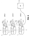
- Fig. 6 illustrates positioning of an embodiment of a device 200 of the present invention so as to optionally simultaneously stimulate various levels (levels 1, 2, 3 in this example) of the spinal cord S.
- the device 200 is shown positioned within an epidural space of the spinal column at a lateral distance from the midline M of the of the spinal column which aligns the device 200 with the dorsal root ganglions DRG 1, DRG 2, DRG 3.
- portions of the device 220 align with and may optionally contact the dorsal root ganglions DRG 1, DRG 2, DRG 3, as indicated by shading.
- These aligned portions provide targeted or selective stimulation of one or more of the dorsal root ganglions DRG 1, DRG 2, DRG 3 while avoiding or reducing stimulation to surrounding tissues, such as the ventral roots VR1, VR2, VR3.
- the device 200 is electrically connected to a power source or implantable pulse generator (IPG) 202, as shown, which is implanted in the body of the patient.
- IPG implantable pulse generator
- Fig. 6 illustrates antegrade positioning of the device 200, however a retrograde approach may also be used.
- the device 200 extends across multiple levels in the form of a grouped lead providing a single extension to the IPG 202, or any number of extensions which is less than the number of targeted levels.
- Fig. 7 provides a side view of the spinal cord S including the bony structures or vertebrae V which surround and protect the spinal cord S.
- the device 200 is shown extending longitudinally through the foramens of each vertebrae V.
- the device 200 may be anchored to a vertebrae V with the use of an anchoring device 204, such as a bone screw or bone tack as shown, to resist migration.
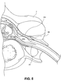
- Fig. 8 provides a cross-sectional view of the device 200 of Fig. 7 showing the device 200 positioned against a DRG. It may be appreciated that the device 200 may be positioned at a variety of locations adjacent or near the DRG while maintaining the longitudinal orientation.
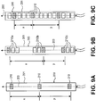
- Figs. 9A-9C illustrate embodiments of devices 200 of the present invention that have electrodes 210 at various spacings and/or allow adjustment of the spacing between activated electrodes.
- Fig. 9A illustrates an embodiment of a device 200 comprising an elongate body 201 having at least two electrodes 210 disposed thereon.
- the elongate body 201 has a longitudinal axis 203, and in this embodiment, the at least two electrodes 210 are disposed along the longitudinal axis 203.
- the at least two electrodes 210 have a fixed spacing along the longitudinal axis 203 according to the distance between spinal levels or the longitudinal distance between DRGs along the spinal column (based on the average patient population or based on specific anatomies).
- Distances X & Y illustrate the distances between the at least two electrodes 210. Distances X & Y may be the same or different from each other. The distances are such that each electrode 210 is within range of a target DRG, when the device 200 is aligned according to Fig. 6 , and each electrode 210 is disposed within a distance which allows selective stimulation thereto.
- Fig. 9B illustrates an embodiment of a device 200 comprising an elongate body 201 having a plurality of electrodes 210 disposed thereon.
- the electrodes 210 are positioned so that two or more electrodes 210 grouped at spaced distances.
- Fig. 9B illustrates a first group of electrodes 210a disposed near a distal end of the elongate body 201, a second group of electrodes 210b disposed midway along the elongate body 201, and a third group of electrodes 210c disposed near a proximal end of the elongate body 201.
- each group 210a, 210b, 210c includes three electrodes disposed along the longitudinal axis 203.
- the electrode 210 within each group 210a, 210b, 210c that aligns most closely with the target DRG of that group or that provides the most desirable therapeutic effects may be utilized (as indicated by shading).
- the remaining two electrodes in the group will not receive stimulating energy. It may be appreciated that in some embodiments, more than one electrode 210 may be used within each group if such use provides a more desirable result.
- the distances X & Y between the stimulating electrodes can thus be varied to accommodate differences in DRG spacing for individual patients.
- the electrodes 210 which receive stimulation energy can be changed without altering the position of the elongate body 201.
- the DRGs can be retargeted by modifying the distances X & Y.
- Fig. 9C also illustrates an embodiment of a device 200 comprising an elongate body 201 having a plurality of electrodes 210 disposed thereon along a longitudinal axis 203.
- the electrodes 210 are positioned substantially continuously along the device 200. Electrodes are selectively utilized (as indicated by shading) to adjust X & Y to accommodate differences in DRG spacing for individual patients. Any number of electrodes may be present in any arrangement. Also, any number of spaced distances may be present, such as to create distances such as X & Y & Z, etc.
- Figs. 10A-10C illustrate an embodiment of a grouped lead device 200 comprising a telescoping shaft 220 which allows adjustable positioning of the electrodes 210.
- the telescoping shaft 220 comprises a first structure or elongate tubular body 220a and a second structure or elongate tubular body 220b.
- Each tubular body 220a, 220b has a proximal end, a distal end and a lumen therethrough.
- Each tubular body 220a, 220b also includes at least one electrode disposed thereon, typically near its distal end.
- the second elongate tubular body is advanceable through the lumen of the first elongate tubular body 220a so that its distal end, and electrode 210 disposed thereon, extends beyond the distal end of the first elongate tubular body 220a.
- the shaft 220 also includes an inner structure 220c having a distal end and, wherein the inner structure is advanceable through the lumen of the second tubular body 220b so that its distal end extends beyond the distal end of the second elongate tubular body 220b.
- the inner structure 220c also has at least one electrode 210 disposed thereon, so that the electrode 210 is exposed beyond the distal end of the second elongate tubular body 220b.
- all three electrodes 210 may be simultaneously exposed and utilized for stimulating tissue.
- the distances X & Y between the electrodes 210 can be adjusted by moving the tubular bodies 220a, 220b and inner structure 220c relative to each other, such as by extension and retraction.
- the telescoping structures 220a, 220b, 220c may be comprised of various materials, preferably a flexible polymer.
- the inner structure 220c has a strength member extending between its proximal and distal ends so as to provide sufficient strength to allow tunneling of the device 200.
- the structures 220a, 220b, 220c may be supported by a stylet during placement.
- the telescoping structures 220a, 220b, 220c may have various cross-sectional shapes, including shapes that resist rotation.
- Fig. 10B illustrates an example of a rotation resisting shape, a flat shape which may be oval or oblong, rectangular, polygonal, etc.
- the flatness of the shape resists rotation of, for example, the inner structure 220c within the second tubular body 220b or the second tubular body 220b within the first tubular body 220a. Such resistance rotation ensures that the electrodes maintain rotational orientation to each other, such as longitudinal alignment.
- the cross-sectional shape may be thick ( Fig. 10C ) which may be circular, square, rectangular, polygonal, etc. When the shape is circular, the rotational orientation of the electrodes can be adjusted.
- Electrodes 210 may be easier to attach to flat designs, conserve energy, etc. Flat designs may also provide easier determination of orientation of the electrodes 210, as describe above, during delivery and implantation.
- the cross-sectional shape may also be chosen based on location in anatomy where the device is to be placed.
- Fig. 11 illustrates the telescoping shaft 220 positioned within the epidural space so that the electrodes 210 are near DRGs on multiple spinal levels. This may be achieved by advancing or retracting the telescoping structures 220a, 220b, 220c so that the electrodes 210 substantially align with the DRGs.
- Conductive wires electrically connected to the electrodes 210 extend out the proximal end to an IPG.
- the above embodiments describe systems that directly stimulate the dorsal root, particularly the dorsal root ganglion (DRG), while minimizing or excluding undesired stimulation of other anatomies.
- this allows access to multiple levels of the spinal column with the use of a single device. This reduces procedure complexity, time and recovery since a single access path is created rather than individual access paths to each level of the spinal column.
- These embodiments also have a reduced number of paths to an IPG. It may be appreciated that the systems of the present invention may also be used to stimulate other portions of the spinal anatomy or other anatomies.
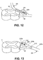
- Fig. 12 illustrates a device 200 such as or similar to the device of Fig. 9C wherein the device 200 comprises an elongate body 201 having a plurality of electrodes 210 disposed substantially continuously thereon along a longitudinal axis 203.
- the device 200 is advanced through the epidural space and at least a portion of the device 200 is advanced laterally toward a single DRG. In some instances, this includes advancement through a foramen.
- the device 200 is positioned so that at least one of the plurality of electrodes 210 is disposed on, near or about the DRG.
- the electrodes are then selectively utilized (as indicated by shading) so that the electrode(s) 210 which provide the most desirable result receive stimulation energy. The remaining electrodes receive a lower level or no stimulation energy.
- Fig. 13 illustrates a device 200 having a telescoping shaft 220 such as or similar to that of Fig. 10A .
- the telescoping shaft 220 comprises a first structure or elongate tubular body 220a and a second structure or elongate tubular body 220b.
- Each tubular body 220a, 220b has a proximal end, a distal end and a lumen therethrough.
- Each tubular body 220a, 220b also includes at least one electrode disposed thereon, typically near its distal end.
- the second elongate tubular body is advanceable through the lumen of the first elongate tubular body 220a so that its distal end, and electrode 210 disposed thereon, extends beyond the distal end of the first elongate tubular body 220a.
- the shaft 220 also includes an inner structure 220c having a distal end and, wherein the inner structure is advanceable through the lumen of the second tubular body 220b so that its distal end extends beyond the distal end of the second elongate tubular body 220b.
- the inner structure 220c also has at least one electrode 210 disposed thereon, so that the electrode 210 is exposed beyond the distal end of the second elongate tubular body 220b. Thus, all three electrodes 210 may be simultaneously exposed and utilized for stimulating tissue.
- Fig. 13 shows the device 200 laterally approaching an individual DRG from outside of a spinal column.
- One or more of the first tubular body 220a, second tubular body 220b and inner structure 220c may be advanced or retracted so that at least one electrode 210 is disposed on, near or about the DRG.
- the electrodes are then selectively utilized (as indicated by shading) so that the electrode(s) 210 which provide the most desirable result receive stimulation energy.
- the remaining electrodes receive a lower level or no stimulation energy.
Landscapes
- Health & Medical Sciences (AREA)
- Neurology (AREA)
- Neurosurgery (AREA)
- Orthopedic Medicine & Surgery (AREA)
- Cardiology (AREA)
- Heart & Thoracic Surgery (AREA)
- Engineering & Computer Science (AREA)
- Biomedical Technology (AREA)
- Nuclear Medicine, Radiotherapy & Molecular Imaging (AREA)
- Radiology & Medical Imaging (AREA)
- Life Sciences & Earth Sciences (AREA)
- Animal Behavior & Ethology (AREA)
- General Health & Medical Sciences (AREA)
- Public Health (AREA)
- Veterinary Medicine (AREA)
- Electrotherapy Devices (AREA)
Applications Claiming Priority (2)
| Application Number | Priority Date | Filing Date | Title |
|---|---|---|---|
| US87346406P | 2006-12-06 | 2006-12-06 | |
| PCT/US2007/086693 WO2008070804A2 (en) | 2006-12-06 | 2007-12-06 | Grouped leads for spinal stimulation |
Publications (3)
| Publication Number | Publication Date |
|---|---|
| EP2094350A2 EP2094350A2 (en) | 2009-09-02 |
| EP2094350A4 EP2094350A4 (en) | 2010-07-14 |
| EP2094350B1 true EP2094350B1 (en) | 2018-06-13 |
Family
ID=39493080
Family Applications (1)
| Application Number | Title | Priority Date | Filing Date |
|---|---|---|---|
| EP07865338.3A Not-in-force EP2094350B1 (en) | 2006-12-06 | 2007-12-06 | Grouped leads for spinal stimulation |
Country Status (7)
| Country | Link |
|---|---|
| US (1) | US20080147156A1 (ja) |
| EP (1) | EP2094350B1 (ja) |
| JP (2) | JP5433420B2 (ja) |
| CN (1) | CN101588839A (ja) |
| AU (1) | AU2007329250B2 (ja) |
| CA (1) | CA2671575A1 (ja) |
| WO (1) | WO2008070804A2 (ja) |
Families Citing this family (38)
| Publication number | Priority date | Publication date | Assignee | Title |
|---|---|---|---|---|
| US9205261B2 (en) | 2004-09-08 | 2015-12-08 | The Board Of Trustees Of The Leland Stanford Junior University | Neurostimulation methods and systems |
| US20120277839A1 (en) | 2004-09-08 | 2012-11-01 | Kramer Jeffery M | Selective stimulation to modulate the sympathetic nervous system |
| US20060052856A1 (en) | 2004-09-08 | 2006-03-09 | Kim Daniel H | Stimulation components |
| JP2010512186A (ja) | 2006-12-06 | 2010-04-22 | スパイナル・モデュレーション・インコーポレイテッド | 硬組織アンカー及び送達装置 |
| AU2007329253B2 (en) | 2006-12-06 | 2014-03-27 | Spinal Modulation, Inc. | Delivery devices, systems and methods for stimulating nerve tissue on multiple spinal levels |
| US11331488B2 (en) | 2007-03-09 | 2022-05-17 | Mainstay Medical Limited | Systems and methods for enhancing function of spine stabilization muscles associated with a spine surgery intervention |
| US9072897B2 (en) | 2007-03-09 | 2015-07-07 | Mainstay Medical Limited | Systems and methods for restoring muscle function to the lumbar spine |
| EP2550991B1 (en) * | 2007-03-09 | 2020-09-02 | Mainstay Medical Limited | Neuromuscular electrical stimulation system |
| US11679262B2 (en) | 2007-03-09 | 2023-06-20 | Mainstay Medical Limited | Systems and methods for restoring muscle function to the lumbar spine |
| US11679261B2 (en) | 2007-03-09 | 2023-06-20 | Mainstay Medical Limited | Systems and methods for enhancing function of spine stabilization muscles associated with a spine surgery intervention |
| BRPI0817544A2 (pt) | 2007-10-10 | 2017-05-02 | Univ Wake Forest Health Sciences | aparelho para tratar tecido de medula espinhal danificado |
| JP5643764B2 (ja) * | 2008-10-27 | 2014-12-17 | スパイナル・モデュレーション・インコーポレイテッドSpinal Modulation Inc. | 選択的刺激システムおよび医学的状態の信号パラメータ |
| US20110130809A1 (en) * | 2008-11-13 | 2011-06-02 | Proteus Biomedical, Inc. | Pacing and Stimulation Apparatus and Methods |
| JP2012508624A (ja) * | 2008-11-13 | 2012-04-12 | プロテウス バイオメディカル インコーポレイテッド | 多重化複数電極神経刺激装置 |
| JP2012508611A (ja) | 2008-11-13 | 2012-04-12 | プロテウス バイオメディカル インコーポレイテッド | 遮蔽された刺激および検出のシステムならびに方法 |
| EP2408518A1 (en) * | 2009-03-09 | 2012-01-25 | Cardiac Pacemakers, Inc. | Systems for autonomic nerve modulation comprising electrodes implantable in a lymphatic vessel |
| JP2012521801A (ja) * | 2009-03-24 | 2012-09-20 | スパイナル・モデュレーション・インコーポレイテッド | 錯感覚に対する閾値以下の刺激を伴う疼痛の管理 |
| WO2010132816A2 (en) | 2009-05-15 | 2010-11-18 | Spinal Modulation, Inc. | Methods, systems and devices for neuromodulating spinal anatomy |
| US12097365B2 (en) | 2010-03-11 | 2024-09-24 | Mainstay Medical Limited | Electrical stimulator for the treatment of back pain and methods of use |
| US11684774B2 (en) | 2010-03-11 | 2023-06-27 | Mainstay Medical Limited | Electrical stimulator for treatment of back pain and methods of use |
| US9950159B2 (en) | 2013-10-23 | 2018-04-24 | Mainstay Medical Limited | Systems and methods for restoring muscle function to the lumbar spine and kits for implanting the same |
| CA2792529C (en) | 2010-03-11 | 2018-06-05 | Mainstay Medical, Inc. | Modular stimulator for treatment of back pain, implantable rf ablation system and methods of use |
| US11786725B2 (en) | 2012-06-13 | 2023-10-17 | Mainstay Medical Limited | Systems and methods for restoring muscle function to the lumbar spine and kits for implanting the same |
| EP2568904B1 (en) | 2010-05-10 | 2019-10-02 | Spinal Modulation Inc. | Device for reducing migration |
| CN103561811A (zh) | 2011-02-02 | 2014-02-05 | 脊髓调制公司 | 靶向治疗运动障碍的装置、系统和方法 |
| ES2829585T3 (es) | 2012-01-25 | 2021-06-01 | Nevro Corp | Anclajes de cables y sistemas y métodos asociados |
| US9675358B2 (en) | 2012-04-12 | 2017-06-13 | Wake Forest University Health Sciences | Conduit for peripheral nerve replacement |
| AU2013266508A1 (en) * | 2012-05-25 | 2014-11-06 | Boston Scientific Neuromodulation Corporation | Methods for stimulating the dorsal root ganglion with a lead having segmented electrodes |
| US10327810B2 (en) | 2016-07-05 | 2019-06-25 | Mainstay Medical Limited | Systems and methods for enhanced implantation of electrode leads between tissue layers |
| EP2911708A4 (en) | 2012-10-26 | 2016-06-22 | Univ Wake Forest Health Sciences | NOVEL NANOFIBER GRAFT FOR REPLACING CARDIAC VALVES AND METHODS OF USING SAME |
| US9265935B2 (en) | 2013-06-28 | 2016-02-23 | Nevro Corporation | Neurological stimulation lead anchors and associated systems and methods |
| US9511230B2 (en) | 2013-11-08 | 2016-12-06 | Nuvectra Corporation | Implantable medical lead for stimulation of multiple nerves |
| US9643003B2 (en) | 2014-11-10 | 2017-05-09 | Steven Sounyoung Yu | Craniofacial neurostimulation for treatment of pain conditions |
| EP3256206B1 (en) * | 2015-02-09 | 2024-05-29 | Boston Scientific Neuromodulation Corporation | System for determining neurological position of epidural leads |
| US10376702B2 (en) * | 2016-04-04 | 2019-08-13 | Boston Scientific Neuromodulation Corporation | System to estimate the location of a spinal cord physiological midline |
| CN109999341A (zh) * | 2018-01-04 | 2019-07-12 | 精能医学股份有限公司 | 电刺激器、制造电刺激器的方法及电刺激系统 |
| CN110013605A (zh) * | 2018-01-10 | 2019-07-16 | 精能医学股份有限公司 | 电刺激器、治疗方法及电刺激系统 |
| AU2019267947A1 (en) * | 2018-05-11 | 2020-11-12 | Synerfuse, Inc. | System, devices, and methods combining spinal stabilization and neuromodulation |
Family Cites Families (97)
| Publication number | Priority date | Publication date | Assignee | Title |
|---|---|---|---|---|
| US3724467A (en) * | 1971-04-23 | 1973-04-03 | Avery Labor Inc | Electrode implant for the neuro-stimulation of the spinal cord |
| US4141367A (en) * | 1977-04-29 | 1979-02-27 | Med Telectronics Ltd. | Cardiac electrode/pacer system analyzer |
| US4374527A (en) * | 1978-07-19 | 1983-02-22 | Medtronic, Inc. | Body stimulation lead |
| US4739764A (en) * | 1984-05-18 | 1988-04-26 | The Regents Of The University Of California | Method for stimulating pelvic floor muscles for regulating pelvic viscera |
| US4590946A (en) * | 1984-06-14 | 1986-05-27 | Biomed Concepts, Inc. | Surgically implantable electrode for nerve bundles |
| US4573481A (en) * | 1984-06-25 | 1986-03-04 | Huntington Institute Of Applied Research | Implantable electrode array |
| US4640286A (en) * | 1984-11-02 | 1987-02-03 | Staodynamics, Inc. | Optimized nerve fiber stimulation |
| US4577642A (en) * | 1985-02-27 | 1986-03-25 | Medtronic, Inc. | Drug dispensing body implantable lead employing molecular sieves and methods of fabrication |
| US4920979A (en) * | 1988-10-12 | 1990-05-01 | Huntington Medical Research Institute | Bidirectional helical electrode for nerve stimulation |
| US5299569A (en) * | 1991-05-03 | 1994-04-05 | Cyberonics, Inc. | Treatment of neuropsychiatric disorders by nerve stimulation |
| US5792187A (en) * | 1993-02-22 | 1998-08-11 | Angeion Corporation | Neuro-stimulation to control pain during cardioversion defibrillation |
| US5411540A (en) * | 1993-06-03 | 1995-05-02 | Massachusetts Institute Of Technology | Method and apparatus for preferential neuron stimulation |
| US5417719A (en) * | 1993-08-25 | 1995-05-23 | Medtronic, Inc. | Method of using a spinal cord stimulation lead |
| US5411537A (en) * | 1993-10-29 | 1995-05-02 | Intermedics, Inc. | Rechargeable biomedical battery powered devices with recharging and control system therefor |
| US5489294A (en) * | 1994-02-01 | 1996-02-06 | Medtronic, Inc. | Steroid eluting stitch-in chronic cardiac lead |
| SE9401267D0 (sv) * | 1994-04-14 | 1994-04-14 | Siemens Elema Ab | Elektrodanordning |
| US5505201A (en) * | 1994-04-20 | 1996-04-09 | Case Western Reserve University | Implantable helical spiral cuff electrode |
| US5514175A (en) * | 1994-11-09 | 1996-05-07 | Cerebral Stimulation, Inc. | Auricular electrical stimulator |
| US5741319A (en) * | 1995-01-27 | 1998-04-21 | Medtronic, Inc. | Biocompatible medical lead |
| US5733322A (en) * | 1995-05-23 | 1998-03-31 | Medtronic, Inc. | Positive fixation percutaneous epidural neurostimulation lead |
| US5755750A (en) * | 1995-11-13 | 1998-05-26 | University Of Florida | Method and apparatus for selectively inhibiting activity in nerve fibers |
| CA2246057C (en) * | 1996-01-31 | 2005-12-20 | Cochlear Limited | Thin film fabrication technique for implantable electrodes |
| US6051017A (en) * | 1996-02-20 | 2000-04-18 | Advanced Bionics Corporation | Implantable microstimulator and systems employing the same |
| US5713922A (en) * | 1996-04-25 | 1998-02-03 | Medtronic, Inc. | Techniques for adjusting the locus of excitation of neural tissue in the spinal cord or brain |
| US5711316A (en) * | 1996-04-30 | 1998-01-27 | Medtronic, Inc. | Method of treating movement disorders by brain infusion |
| US5885290A (en) * | 1996-12-09 | 1999-03-23 | Guerrero; Cesar A. | Intra-oral bone distraction device |
| US5865843A (en) * | 1997-04-23 | 1999-02-02 | Medtronic Inc. | Medical neurological lead with integral fixation mechanism |
| US6839588B1 (en) * | 1997-07-31 | 2005-01-04 | Case Western Reserve University | Electrophysiological cardiac mapping system based on a non-contact non-expandable miniature multi-electrode catheter and method therefor |
| US5871531A (en) * | 1997-09-25 | 1999-02-16 | Medtronic, Inc. | Medical electrical lead having tapered spiral fixation |
| US6045532A (en) * | 1998-02-20 | 2000-04-04 | Arthrocare Corporation | Systems and methods for electrosurgical treatment of tissue in the brain and spinal cord |
| US6161047A (en) * | 1998-04-30 | 2000-12-12 | Medtronic Inc. | Apparatus and method for expanding a stimulation lead body in situ |
| US6319241B1 (en) * | 1998-04-30 | 2001-11-20 | Medtronic, Inc. | Techniques for positioning therapy delivery elements within a spinal cord or a brain |
| US7599736B2 (en) * | 2001-07-23 | 2009-10-06 | Dilorenzo Biomedical, Llc | Method and apparatus for neuromodulation and physiologic modulation for the treatment of metabolic and neuropsychiatric disease |
| US6044297A (en) * | 1998-09-25 | 2000-03-28 | Medtronic, Inc. | Posture and device orientation and calibration for implantable medical devices |
| US6366814B1 (en) * | 1998-10-26 | 2002-04-02 | Birinder R. Boveja | External stimulator for adjunct (add-on) treatment for neurological, neuropsychiatric, and urological disorders |
| US6208902B1 (en) * | 1998-10-26 | 2001-03-27 | Birinder Bob Boveja | Apparatus and method for adjunct (add-on) therapy for pain syndromes utilizing an implantable lead and an external stimulator |
| US6393325B1 (en) * | 1999-01-07 | 2002-05-21 | Advanced Bionics Corporation | Directional programming for implantable electrode arrays |
| US6436099B1 (en) * | 1999-04-23 | 2002-08-20 | Sdgi Holdings, Inc. | Adjustable spinal tether |
| US6055456A (en) * | 1999-04-29 | 2000-04-25 | Medtronic, Inc. | Single and multi-polar implantable lead for sacral nerve electrical stimulation |
| US6214016B1 (en) * | 1999-04-29 | 2001-04-10 | Medtronic, Inc. | Medical instrument positioning device internal to a catheter or lead and method of use |
| US6353762B1 (en) * | 1999-04-30 | 2002-03-05 | Medtronic, Inc. | Techniques for selective activation of neurons in the brain, spinal cord parenchyma or peripheral nerve |
| US6516227B1 (en) * | 1999-07-27 | 2003-02-04 | Advanced Bionics Corporation | Rechargeable spinal cord stimulator system |
| US6517542B1 (en) * | 1999-08-04 | 2003-02-11 | The Cleveland Clinic Foundation | Bone anchoring system |
| US7047082B1 (en) * | 1999-09-16 | 2006-05-16 | Micronet Medical, Inc. | Neurostimulating lead |
| US6356786B1 (en) * | 2000-01-20 | 2002-03-12 | Electrocore Techniques, Llc | Method of treating palmar hyperhydrosis by electrical stimulation of the sympathetic nervous chain |
| US7181289B2 (en) * | 2000-03-20 | 2007-02-20 | Pflueger D Russell | Epidural nerve root access catheter and treatment methods |
| US6510347B2 (en) * | 2000-08-17 | 2003-01-21 | William N. Borkan | Spinal cord stimulation leads |
| US6871099B1 (en) * | 2000-08-18 | 2005-03-22 | Advanced Bionics Corporation | Fully implantable microstimulator for spinal cord stimulation as a therapy for chronic pain |
| US6862479B1 (en) * | 2000-08-30 | 2005-03-01 | Advanced Bionics Corporation | Spinal cord stimulation as a therapy for sexual dysfunction |
| US7043299B2 (en) * | 2000-09-18 | 2006-05-09 | Cameron Health, Inc. | Subcutaneous implantable cardioverter-defibrillator employing a telescoping lead |
| US6522926B1 (en) * | 2000-09-27 | 2003-02-18 | Cvrx, Inc. | Devices and methods for cardiovascular reflex control |
| US6901287B2 (en) * | 2001-02-09 | 2005-05-31 | Medtronic, Inc. | Implantable therapy delivery element adjustable anchor |
| US6873342B2 (en) * | 2001-04-12 | 2005-03-29 | Mitsubishi Electric Research Laboratories, Inc. | Method for generating detail directed visibility elements for a graphics model |
| US6892098B2 (en) * | 2001-04-26 | 2005-05-10 | Biocontrol Medical Ltd. | Nerve stimulation for treating spasticity, tremor, muscle weakness, and other motor disorders |
| US6512958B1 (en) * | 2001-04-26 | 2003-01-28 | Medtronic, Inc. | Percutaneous medical probe and flexible guide wire |
| US6554809B2 (en) * | 2001-08-02 | 2003-04-29 | Teodulo Aves | Epidural catheter needle |
| US6535767B1 (en) * | 2001-08-21 | 2003-03-18 | James W. Kronberg | Apparatus and method for bioelectric stimulation, healing acceleration and pain relief |
| US20030069569A1 (en) * | 2001-08-29 | 2003-04-10 | Burdette Everette C. | Ultrasound device for treatment of intervertebral disc tissue |
| US6999819B2 (en) * | 2001-08-31 | 2006-02-14 | Medtronic, Inc. | Implantable medical electrical stimulation lead fixation method and apparatus |
| WO2003026736A2 (en) * | 2001-09-28 | 2003-04-03 | Northstar Neuroscience, Inc. | Methods and implantable apparatus for electrical therapy |
| US6745079B2 (en) * | 2001-11-07 | 2004-06-01 | Medtronic, Inc. | Electrical tissue stimulation apparatus and method |
| AUPS101502A0 (en) * | 2002-03-11 | 2002-04-11 | Neopraxis Pty Ltd | Wireless fes system |
| US7146222B2 (en) * | 2002-04-15 | 2006-12-05 | Neurospace, Inc. | Reinforced sensing and stimulation leads and use in detection systems |
| US20040015202A1 (en) * | 2002-06-14 | 2004-01-22 | Chandler Gilbert S. | Combination epidural infusion/stimulation method and system |
| WO2004007018A1 (en) * | 2002-07-17 | 2004-01-22 | Remidi (Uk) Limited | Apparatus for the application of electrical pulses to the human body |
| US7993351B2 (en) * | 2002-07-24 | 2011-08-09 | Pressure Products Medical Supplies, Inc. | Telescopic introducer with a compound curvature for inducing alignment and method of using the same |
| US7107105B2 (en) * | 2002-09-24 | 2006-09-12 | Medtronic, Inc. | Deployable medical lead fixation system and method |
| US7069083B2 (en) * | 2002-12-13 | 2006-06-27 | Advanced Neuromodulation Systems, Inc. | System and method for electrical stimulation of the intervertebral disc |
| US20050027338A1 (en) * | 2003-07-29 | 2005-02-03 | Advanced Neuromodulation Systems, Inc. | Stretchable lead body, method of manufacture, and system |
| US7794476B2 (en) * | 2003-08-08 | 2010-09-14 | Warsaw Orthopedic, Inc. | Implants formed of shape memory polymeric material for spinal fixation |
| US20050033393A1 (en) * | 2003-08-08 | 2005-02-10 | Advanced Neuromodulation Systems, Inc. | Apparatus and method for implanting an electrical stimulation system and a paddle style electrical stimulation lead |
| US20050038489A1 (en) * | 2003-08-14 | 2005-02-17 | Grill Warren M. | Electrode array for use in medical stimulation and methods thereof |
| US7930037B2 (en) * | 2003-09-30 | 2011-04-19 | Medtronic, Inc. | Field steerable electrical stimulation paddle, lead system, and medical device incorporating the same |
| US20050080325A1 (en) * | 2003-10-14 | 2005-04-14 | Advanced Neuromodulation Systems, Inc. | Low profile connector and system for implantable medical device |
| US7437197B2 (en) * | 2003-10-23 | 2008-10-14 | Medtronic, Inc. | Medical lead and manufacturing method therefor |
| US8260436B2 (en) * | 2003-10-31 | 2012-09-04 | Medtronic, Inc. | Implantable stimulation lead with fixation mechanism |
| US7174219B2 (en) * | 2004-03-30 | 2007-02-06 | Medtronic, Inc. | Lead electrode for use in an MRI-safe implantable medical device |
| AU2005310320B2 (en) * | 2004-06-02 | 2012-02-09 | Kfx Medical Corporation | System and method for attaching soft tissue to bone |
| US7395120B2 (en) * | 2004-08-13 | 2008-07-01 | The General Hospital Corporation | Telescoping, dual-site pacing lead |
| US20060041295A1 (en) * | 2004-08-17 | 2006-02-23 | Osypka Thomas P | Positive fixation percutaneous epidural neurostimulation lead |
| US20060052856A1 (en) * | 2004-09-08 | 2006-03-09 | Kim Daniel H | Stimulation components |
| US7553307B2 (en) * | 2004-10-15 | 2009-06-30 | Baxano, Inc. | Devices and methods for tissue modification |
| WO2006047291A2 (en) * | 2004-10-21 | 2006-05-04 | Advanced Neuromodulation Systems, Inc. | Spinal cord stimulation to treat auditory dysfunction |
| US20060089696A1 (en) * | 2004-10-21 | 2006-04-27 | Medtronic, Inc. | Implantable medical lead with reinforced outer jacket |
| US20080009927A1 (en) * | 2005-01-11 | 2008-01-10 | Vilims Bradley D | Combination Electrical Stimulating and Infusion Medical Device and Method |
| US20060167525A1 (en) * | 2005-01-19 | 2006-07-27 | Medtronic, Inc. | Method of stimulating multiple sites |
| GB2423020A (en) * | 2005-02-14 | 2006-08-16 | Algotec Ltd | Percutaneous electrical stimulation probe for pain relief |
| US20070060954A1 (en) * | 2005-02-25 | 2007-03-15 | Tracy Cameron | Method of using spinal cord stimulation to treat neurological disorders or conditions |
| US20060206178A1 (en) * | 2005-03-11 | 2006-09-14 | Kim Daniel H | Percutaneous endoscopic access tools for the spinal epidural space and related methods of treatment |
| US7672727B2 (en) * | 2005-08-17 | 2010-03-02 | Enteromedics Inc. | Neural electrode treatment |
| US7979131B2 (en) * | 2006-01-26 | 2011-07-12 | Advanced Neuromodulation Systems, Inc. | Method of neurostimulation of distinct neural structures using single paddle lead to treat multiple pain locations and multi-column, multi-row paddle lead for such neurostimulation |
| US20080033431A1 (en) * | 2006-06-29 | 2008-02-07 | Searete Llc, A Limited Liability Corporation Of The State Of Delaware | Position augmenting mechanism |
| US20080039916A1 (en) * | 2006-08-08 | 2008-02-14 | Olivier Colliou | Distally distributed multi-electrode lead |
| US20080103580A1 (en) * | 2006-10-31 | 2008-05-01 | Medtronic, Inc. | Implantable medical elongated member with dual purpose conduit |
| US9643004B2 (en) * | 2006-10-31 | 2017-05-09 | Medtronic, Inc. | Implantable medical elongated member with adhesive elements |
| US20080103572A1 (en) * | 2006-10-31 | 2008-05-01 | Medtronic, Inc. | Implantable medical lead with threaded fixation |
| US7853303B2 (en) * | 2006-11-16 | 2010-12-14 | National Research Council Of Canada | Neurological probe and method of using same |
-
2007
- 2007-12-06 JP JP2009540485A patent/JP5433420B2/ja not_active Expired - Fee Related
- 2007-12-06 EP EP07865338.3A patent/EP2094350B1/en not_active Not-in-force
- 2007-12-06 AU AU2007329250A patent/AU2007329250B2/en not_active Ceased
- 2007-12-06 WO PCT/US2007/086693 patent/WO2008070804A2/en active Application Filing
- 2007-12-06 CN CNA2007800450872A patent/CN101588839A/zh active Pending
- 2007-12-06 CA CA002671575A patent/CA2671575A1/en not_active Abandoned
- 2007-12-06 US US11/952,049 patent/US20080147156A1/en not_active Abandoned
-
2013
- 2013-08-09 JP JP2013166689A patent/JP5759519B2/ja active Active
Also Published As
| Publication number | Publication date |
|---|---|
| JP5759519B2 (ja) | 2015-08-05 |
| JP2010512185A (ja) | 2010-04-22 |
| EP2094350A2 (en) | 2009-09-02 |
| CN101588839A (zh) | 2009-11-25 |
| JP2013240710A (ja) | 2013-12-05 |
| WO2008070804A2 (en) | 2008-06-12 |
| JP5433420B2 (ja) | 2014-03-05 |
| US20080147156A1 (en) | 2008-06-19 |
| CA2671575A1 (en) | 2008-06-12 |
| EP2094350A4 (en) | 2010-07-14 |
| AU2007329250A1 (en) | 2008-06-12 |
| AU2007329250B2 (en) | 2012-03-15 |
| WO2008070804A3 (en) | 2008-09-25 |
Similar Documents
| Publication | Publication Date | Title |
|---|---|---|
| EP2094350B1 (en) | Grouped leads for spinal stimulation | |
| EP2091594B1 (en) | Delivery devices for stimulating nerve tissue on multiple spinal levels | |
| US9427570B2 (en) | Expandable stimulation leads and methods of use | |
| AU766099B2 (en) | Epidural nerve root stimulation | |
| US20180207419A1 (en) | Implantable flexible circuit leads and methods of use | |
| US9468762B2 (en) | Pain management with stimulation subthreshold to paresthesia | |
| EP1904154B1 (en) | Implantable medical lead | |
| US20140100586A1 (en) | Insertion tool for paddle-style electrode | |
| AU4013999A (en) | Epidural nerve root stimulation | |
| AU2014202705B2 (en) | Grouped leads for spinal stimulation | |
| AU2012203467B2 (en) | Grouped leads for spinal stimulation | |
| AU2014201494B2 (en) | Delivery Devices, Systems and Methods for Stimulating Nerve Tissue on Multiple Spinal Levels |
Legal Events
| Date | Code | Title | Description |
|---|---|---|---|
| PUAI | Public reference made under article 153(3) epc to a published international application that has entered the european phase |
Free format text: ORIGINAL CODE: 0009012 |
|
| 17P | Request for examination filed |
Effective date: 20090706 |
|
| AK | Designated contracting states |
Kind code of ref document: A2 Designated state(s): AT BE BG CH CY CZ DE DK EE ES FI FR GB GR HU IE IS IT LI LT LU LV MC MT NL PL PT RO SE SI SK TR |
|
| DAX | Request for extension of the european patent (deleted) | ||
| A4 | Supplementary search report drawn up and despatched |
Effective date: 20100614 |
|
| RIC1 | Information provided on ipc code assigned before grant |
Ipc: A61N 1/05 20060101AFI20100608BHEP |
|
| STAA | Information on the status of an ep patent application or granted ep patent |
Free format text: STATUS: EXAMINATION IS IN PROGRESS |
|
| 17Q | First examination report despatched |
Effective date: 20170808 |
|
| GRAP | Despatch of communication of intention to grant a patent |
Free format text: ORIGINAL CODE: EPIDOSNIGR1 |
|
| STAA | Information on the status of an ep patent application or granted ep patent |
Free format text: STATUS: GRANT OF PATENT IS INTENDED |
|
| INTG | Intention to grant announced |
Effective date: 20171211 |
|
| GRAJ | Information related to disapproval of communication of intention to grant by the applicant or resumption of examination proceedings by the epo deleted |
Free format text: ORIGINAL CODE: EPIDOSDIGR1 |
|
| STAA | Information on the status of an ep patent application or granted ep patent |
Free format text: STATUS: EXAMINATION IS IN PROGRESS |
|
| GRAR | Information related to intention to grant a patent recorded |
Free format text: ORIGINAL CODE: EPIDOSNIGR71 |
|
| GRAS | Grant fee paid |
Free format text: ORIGINAL CODE: EPIDOSNIGR3 |
|
| STAA | Information on the status of an ep patent application or granted ep patent |
Free format text: STATUS: GRANT OF PATENT IS INTENDED |
|
| GRAA | (expected) grant |
Free format text: ORIGINAL CODE: 0009210 |
|
| STAA | Information on the status of an ep patent application or granted ep patent |
Free format text: STATUS: THE PATENT HAS BEEN GRANTED |
|
| INTC | Intention to grant announced (deleted) | ||
| AK | Designated contracting states |
Kind code of ref document: B1 Designated state(s): AT BE BG CH CY CZ DE DK EE ES FI FR GB GR HU IE IS IT LI LT LU LV MC MT NL PL PT RO SE SI SK TR |
|
| INTG | Intention to grant announced |
Effective date: 20180504 |
|
| REG | Reference to a national code |
Ref country code: GB Ref legal event code: FG4D |
|
| REG | Reference to a national code |
Ref country code: CH Ref legal event code: EP Ref country code: AT Ref legal event code: REF Ref document number: 1007842 Country of ref document: AT Kind code of ref document: T Effective date: 20180615 |
|
| REG | Reference to a national code |
Ref country code: IE Ref legal event code: FG4D |
|
| REG | Reference to a national code |
Ref country code: DE Ref legal event code: R096 Ref document number: 602007055125 Country of ref document: DE |
|
| REG | Reference to a national code |
Ref country code: NL Ref legal event code: MP Effective date: 20180613 |
|
| REG | Reference to a national code |
Ref country code: LT Ref legal event code: MG4D |
|
| PG25 | Lapsed in a contracting state [announced via postgrant information from national office to epo] |
Ref country code: ES Free format text: LAPSE BECAUSE OF FAILURE TO SUBMIT A TRANSLATION OF THE DESCRIPTION OR TO PAY THE FEE WITHIN THE PRESCRIBED TIME-LIMIT Effective date: 20180613 Ref country code: CY Free format text: LAPSE BECAUSE OF FAILURE TO SUBMIT A TRANSLATION OF THE DESCRIPTION OR TO PAY THE FEE WITHIN THE PRESCRIBED TIME-LIMIT Effective date: 20180613 Ref country code: BG Free format text: LAPSE BECAUSE OF FAILURE TO SUBMIT A TRANSLATION OF THE DESCRIPTION OR TO PAY THE FEE WITHIN THE PRESCRIBED TIME-LIMIT Effective date: 20180913 Ref country code: FI Free format text: LAPSE BECAUSE OF FAILURE TO SUBMIT A TRANSLATION OF THE DESCRIPTION OR TO PAY THE FEE WITHIN THE PRESCRIBED TIME-LIMIT Effective date: 20180613 Ref country code: LT Free format text: LAPSE BECAUSE OF FAILURE TO SUBMIT A TRANSLATION OF THE DESCRIPTION OR TO PAY THE FEE WITHIN THE PRESCRIBED TIME-LIMIT Effective date: 20180613 Ref country code: SE Free format text: LAPSE BECAUSE OF FAILURE TO SUBMIT A TRANSLATION OF THE DESCRIPTION OR TO PAY THE FEE WITHIN THE PRESCRIBED TIME-LIMIT Effective date: 20180613 |
|
| PG25 | Lapsed in a contracting state [announced via postgrant information from national office to epo] |
Ref country code: GR Free format text: LAPSE BECAUSE OF FAILURE TO SUBMIT A TRANSLATION OF THE DESCRIPTION OR TO PAY THE FEE WITHIN THE PRESCRIBED TIME-LIMIT Effective date: 20180914 Ref country code: LV Free format text: LAPSE BECAUSE OF FAILURE TO SUBMIT A TRANSLATION OF THE DESCRIPTION OR TO PAY THE FEE WITHIN THE PRESCRIBED TIME-LIMIT Effective date: 20180613 |
|
| REG | Reference to a national code |
Ref country code: AT Ref legal event code: MK05 Ref document number: 1007842 Country of ref document: AT Kind code of ref document: T Effective date: 20180613 |
|
| PG25 | Lapsed in a contracting state [announced via postgrant information from national office to epo] |
Ref country code: NL Free format text: LAPSE BECAUSE OF FAILURE TO SUBMIT A TRANSLATION OF THE DESCRIPTION OR TO PAY THE FEE WITHIN THE PRESCRIBED TIME-LIMIT Effective date: 20180613 |
|
| PG25 | Lapsed in a contracting state [announced via postgrant information from national office to epo] |
Ref country code: CZ Free format text: LAPSE BECAUSE OF FAILURE TO SUBMIT A TRANSLATION OF THE DESCRIPTION OR TO PAY THE FEE WITHIN THE PRESCRIBED TIME-LIMIT Effective date: 20180613 Ref country code: RO Free format text: LAPSE BECAUSE OF FAILURE TO SUBMIT A TRANSLATION OF THE DESCRIPTION OR TO PAY THE FEE WITHIN THE PRESCRIBED TIME-LIMIT Effective date: 20180613 Ref country code: SK Free format text: LAPSE BECAUSE OF FAILURE TO SUBMIT A TRANSLATION OF THE DESCRIPTION OR TO PAY THE FEE WITHIN THE PRESCRIBED TIME-LIMIT Effective date: 20180613 Ref country code: IS Free format text: LAPSE BECAUSE OF FAILURE TO SUBMIT A TRANSLATION OF THE DESCRIPTION OR TO PAY THE FEE WITHIN THE PRESCRIBED TIME-LIMIT Effective date: 20181013 Ref country code: AT Free format text: LAPSE BECAUSE OF FAILURE TO SUBMIT A TRANSLATION OF THE DESCRIPTION OR TO PAY THE FEE WITHIN THE PRESCRIBED TIME-LIMIT Effective date: 20180613 Ref country code: PL Free format text: LAPSE BECAUSE OF FAILURE TO SUBMIT A TRANSLATION OF THE DESCRIPTION OR TO PAY THE FEE WITHIN THE PRESCRIBED TIME-LIMIT Effective date: 20180613 Ref country code: EE Free format text: LAPSE BECAUSE OF FAILURE TO SUBMIT A TRANSLATION OF THE DESCRIPTION OR TO PAY THE FEE WITHIN THE PRESCRIBED TIME-LIMIT Effective date: 20180613 |
|
| PGFP | Annual fee paid to national office [announced via postgrant information from national office to epo] |
Ref country code: DE Payment date: 20181114 Year of fee payment: 12 |
|
| PG25 | Lapsed in a contracting state [announced via postgrant information from national office to epo] |
Ref country code: IT Free format text: LAPSE BECAUSE OF FAILURE TO SUBMIT A TRANSLATION OF THE DESCRIPTION OR TO PAY THE FEE WITHIN THE PRESCRIBED TIME-LIMIT Effective date: 20180613 |
|
| PGFP | Annual fee paid to national office [announced via postgrant information from national office to epo] |
Ref country code: GB Payment date: 20181129 Year of fee payment: 12 Ref country code: FR Payment date: 20181119 Year of fee payment: 12 |
|
| REG | Reference to a national code |
Ref country code: DE Ref legal event code: R097 Ref document number: 602007055125 Country of ref document: DE |
|
| PLBE | No opposition filed within time limit |
Free format text: ORIGINAL CODE: 0009261 |
|
| STAA | Information on the status of an ep patent application or granted ep patent |
Free format text: STATUS: NO OPPOSITION FILED WITHIN TIME LIMIT |
|
| 26N | No opposition filed |
Effective date: 20190314 |
|
| PG25 | Lapsed in a contracting state [announced via postgrant information from national office to epo] |
Ref country code: SI Free format text: LAPSE BECAUSE OF FAILURE TO SUBMIT A TRANSLATION OF THE DESCRIPTION OR TO PAY THE FEE WITHIN THE PRESCRIBED TIME-LIMIT Effective date: 20180613 Ref country code: DK Free format text: LAPSE BECAUSE OF FAILURE TO SUBMIT A TRANSLATION OF THE DESCRIPTION OR TO PAY THE FEE WITHIN THE PRESCRIBED TIME-LIMIT Effective date: 20180613 |
|
| REG | Reference to a national code |
Ref country code: CH Ref legal event code: PL |
|
| PG25 | Lapsed in a contracting state [announced via postgrant information from national office to epo] |
Ref country code: LU Free format text: LAPSE BECAUSE OF NON-PAYMENT OF DUE FEES Effective date: 20181206 Ref country code: MC Free format text: LAPSE BECAUSE OF FAILURE TO SUBMIT A TRANSLATION OF THE DESCRIPTION OR TO PAY THE FEE WITHIN THE PRESCRIBED TIME-LIMIT Effective date: 20180613 |
|
| REG | Reference to a national code |
Ref country code: IE Ref legal event code: MM4A |
|
| REG | Reference to a national code |
Ref country code: BE Ref legal event code: MM Effective date: 20181231 |
|
| PG25 | Lapsed in a contracting state [announced via postgrant information from national office to epo] |
Ref country code: IE Free format text: LAPSE BECAUSE OF NON-PAYMENT OF DUE FEES Effective date: 20181206 |
|
| PG25 | Lapsed in a contracting state [announced via postgrant information from national office to epo] |
Ref country code: BE Free format text: LAPSE BECAUSE OF NON-PAYMENT OF DUE FEES Effective date: 20181231 |
|
| PG25 | Lapsed in a contracting state [announced via postgrant information from national office to epo] |
Ref country code: CH Free format text: LAPSE BECAUSE OF NON-PAYMENT OF DUE FEES Effective date: 20181231 Ref country code: LI Free format text: LAPSE BECAUSE OF NON-PAYMENT OF DUE FEES Effective date: 20181231 |
|
| PG25 | Lapsed in a contracting state [announced via postgrant information from national office to epo] |
Ref country code: MT Free format text: LAPSE BECAUSE OF NON-PAYMENT OF DUE FEES Effective date: 20181206 |
|
| PG25 | Lapsed in a contracting state [announced via postgrant information from national office to epo] |
Ref country code: TR Free format text: LAPSE BECAUSE OF FAILURE TO SUBMIT A TRANSLATION OF THE DESCRIPTION OR TO PAY THE FEE WITHIN THE PRESCRIBED TIME-LIMIT Effective date: 20180613 |
|
| PG25 | Lapsed in a contracting state [announced via postgrant information from national office to epo] |
Ref country code: PT Free format text: LAPSE BECAUSE OF FAILURE TO SUBMIT A TRANSLATION OF THE DESCRIPTION OR TO PAY THE FEE WITHIN THE PRESCRIBED TIME-LIMIT Effective date: 20180613 |
|
| PG25 | Lapsed in a contracting state [announced via postgrant information from national office to epo] |
Ref country code: HU Free format text: LAPSE BECAUSE OF FAILURE TO SUBMIT A TRANSLATION OF THE DESCRIPTION OR TO PAY THE FEE WITHIN THE PRESCRIBED TIME-LIMIT; INVALID AB INITIO Effective date: 20071206 |
|
| REG | Reference to a national code |
Ref country code: DE Ref legal event code: R119 Ref document number: 602007055125 Country of ref document: DE |
|
| GBPC | Gb: european patent ceased through non-payment of renewal fee |
Effective date: 20191206 |
|
| PG25 | Lapsed in a contracting state [announced via postgrant information from national office to epo] |
Ref country code: FR Free format text: LAPSE BECAUSE OF NON-PAYMENT OF DUE FEES Effective date: 20191231 Ref country code: GB Free format text: LAPSE BECAUSE OF NON-PAYMENT OF DUE FEES Effective date: 20191206 Ref country code: DE Free format text: LAPSE BECAUSE OF NON-PAYMENT OF DUE FEES Effective date: 20200701 |