EP2094022B1 - Verfahren für den Zugriff auf mehrere Koppelfelder - Google Patents
Verfahren für den Zugriff auf mehrere Koppelfelder Download PDFInfo
- Publication number
- EP2094022B1 EP2094022B1 EP08300108A EP08300108A EP2094022B1 EP 2094022 B1 EP2094022 B1 EP 2094022B1 EP 08300108 A EP08300108 A EP 08300108A EP 08300108 A EP08300108 A EP 08300108A EP 2094022 B1 EP2094022 B1 EP 2094022B1
- Authority
- EP
- European Patent Office
- Prior art keywords
- flows
- input
- output
- switching
- groups
- Prior art date
- Legal status (The legal status is an assumption and is not a legal conclusion. Google has not performed a legal analysis and makes no representation as to the accuracy of the status listed.)
- Not-in-force
Links
- 239000004744 fabric Substances 0.000 title claims abstract description 75
- 238000000034 method Methods 0.000 title claims abstract description 38
- 239000011159 matrix material Substances 0.000 claims description 38
- 230000005540 biological transmission Effects 0.000 claims description 6
- 238000004590 computer program Methods 0.000 claims description 6
- 101710143616 Ubiquitin-associated and SH3 domain-containing protein B Proteins 0.000 description 127
- 102100040338 Ubiquitin-associated and SH3 domain-containing protein B Human genes 0.000 description 127
- 230000015654 memory Effects 0.000 description 19
- 230000006870 function Effects 0.000 description 15
- 101150080585 memb-1 gene Proteins 0.000 description 10
- RGNPBRKPHBKNKX-UHFFFAOYSA-N hexaflumuron Chemical compound C1=C(Cl)C(OC(F)(F)C(F)F)=C(Cl)C=C1NC(=O)NC(=O)C1=C(F)C=CC=C1F RGNPBRKPHBKNKX-UHFFFAOYSA-N 0.000 description 7
- 230000000903 blocking effect Effects 0.000 description 4
- 230000008901 benefit Effects 0.000 description 3
- 239000000872 buffer Substances 0.000 description 3
- 230000004048 modification Effects 0.000 description 2
- 238000012986 modification Methods 0.000 description 2
- 230000008707 rearrangement Effects 0.000 description 2
- 101150018075 sel-2 gene Proteins 0.000 description 2
- 230000004913 activation Effects 0.000 description 1
- 230000003287 optical effect Effects 0.000 description 1
Images

Classifications
-
- H—ELECTRICITY
- H04—ELECTRIC COMMUNICATION TECHNIQUE
- H04Q—SELECTING
- H04Q3/00—Selecting arrangements
- H04Q3/64—Distributing or queueing
- H04Q3/68—Grouping or interlacing selector groups or stages
-
- H—ELECTRICITY
- H04—ELECTRIC COMMUNICATION TECHNIQUE
- H04L—TRANSMISSION OF DIGITAL INFORMATION, e.g. TELEGRAPHIC COMMUNICATION
- H04L49/00—Packet switching elements
- H04L49/15—Interconnection of switching modules
- H04L49/1515—Non-blocking multistage, e.g. Clos
- H04L49/1523—Parallel switch fabric planes
-
- H—ELECTRICITY
- H04—ELECTRIC COMMUNICATION TECHNIQUE
- H04L—TRANSMISSION OF DIGITAL INFORMATION, e.g. TELEGRAPHIC COMMUNICATION
- H04L49/00—Packet switching elements
- H04L49/55—Prevention, detection or correction of errors
- H04L49/552—Prevention, detection or correction of errors by ensuring the integrity of packets received through redundant connections
Definitions
- the present invention relates to the telecommunication field and more in particular to a method for performing the switching of digital signals. Still more in particular, the invention concerns a method for accessing a plurality of fabric switches.
- a first solution to the above problem is an architecture composed of multiple switching stages like the Clos architecture, which is composed of three stages and which has the advantage to require less crosspoints than a single switching matrix.
- the Clos architecture is re-arrangeably non-blocking (that is, an unused input can always be connected to an unused output, but the configured cross-connections must be re-arranged by assigning them to different crossbar switches of the second stage) or strictly non-blocking (an unused input can always be connected to an unused output, without rearranging the configured cross-connections).
- a re-arrangeably non-blocking Clos architecture requires the reconfiguration of the existing cross-connections, which is time consuming: in case of requiring the configuration of a new cross-connection after a failure on a cross-connection, the time spent for the re-arrangement of the existing cross-connections and for the configuration of the new cross-connection is too high (for example, more than 2 ms) and this has the disadvantage that a lot of data carried over the failed cross-connection is lost during this time
- a strictly non-blocking Clos architecture does not require the reconfiguration of the existing cross-connections, but it requires an high number of crossbar switches in the second stage, which has the disadvantage to be expensive and also not feasible.
- Clos architecture has the disadvantage to require a coordination of the 3 stages and thus a complex control algorithm.
- a second solution to the above problem is to perform a parallel switching (also indicated with “slicing”).
- a signal carried over an input is sliced into several parts (for example, every byte of the signal is divided into 8 bits) and the different parts (slices) of the signal are sent to different switching matrices. This is performed for every input and thus each switching matrix performs the cross-connection of one slice of all the inputs (in the example, every switching matrix requires a switching capacity of 1/8 of the capacity of the total switching function).
- This second solution is not feasible in case of a switching function including many inputs/ outputs, because it would require an high number of slices and thus an high number of parallel switching matrices.
- a third solutions to the above problem is to split the flow received from each input into a number of flows equal to the number of the outputs, to send the splitted flows to corresponding buffers and each output can select the flow from any buffer.
- This third solution has the disadvantage to require an high number of buffers, equal to the number of inputs multiplied by the number of outputs.
- the main object of the present invention is to provide a method for performing a switching function for cross-connections between a plurality of inputs and a plurality of outputs by using a plurality of smaller fabric switches.
- This object is achieved by a method according to claim 1.
- the basic idea is to generate a plurality of "logical" input flows from the inputs of the switching function, to arrange the "logical" input flows into a plurality of groups including a number of "logical” flows such that the plurality of groups can be switched by a plurality of fabric switches, and to select output logical flows from the switched flows.
- Advantages of the invention are not to require the re-arrangement of the configured cross-connections in case of configuring a new cross-connection, to require less fabric switches respect to the Clos architecture and to require a less complex algorithm for controlling the switching system.
- the present invention provides a method for switching digital signals.
- the method includes the steps of generating multiple input flows from multiple inputs, the number of the multiple input flows being higher than the number of the multiple inputs; arranging the multiple input flows into first multiple groups of flows taking into account the switching capacity of at least two fabric switches, the number of flows switched by each of the at least two fabric switches being smaller than the number of the multiple input flows; duplicating the first multiple groups of flows into at least one corresponding copy; arranging the first multiple groups and the at least one corresponding copy into second multiple groups of flows; switching flows of the second multiple groups into the at least two fabric switches; selecting multiple output flows from at least part of the switched flows of the second multiple groups.
- the first multiple groups and the copies are arranged into different second multiple groups.
- the arrangement into the second multiple groups is such that at least one second group includes a group out of the first multiple groups and the copy of another group out of the first multiple groups.
- the method further includes the step of dividing at least one of the second groups of flows into third multiple groups of flows and the step of slicing the flows of the third groups over the at least two fabric switches.
- At least two fabric switches are arranged into multiple switching planes and the switching of the second multiple groups is performed into different switching planes.
- the multiple inputs are multiple input ports and one group out of the first multiple groups includes the input flows generated from different input ports.
- one of the multiple switching planes includes a plurality of fabric switches and the method further includes the step of slicing the flows of a group out of the second multiple groups, wherein the step of switching the flows of the group includes the switching of the sliced flows over the plurality of fabric switches.
- the multiple inputs are multiple input ports and a first input line card is adapted to receive the first multiple input ports, wherein a matrix board includes the at least two fabric switches and an output line card is adapted to generate the multiple output ports.
- the step of duplicating is performed at the transmission side the first input line card.
- the step of selecting is performed at the reception side of the output line card.
- the step of duplicating is performed at the reception side of the matrix board and the step of selecting is performed at the transmission side of the matrix board.
- the step of arranging the multiple input flows further takes into account the capacity of links between the input line card and the matrix board.
- the method further includes the step of generating in the matrix board control information from configuration information indicating the cross-connections between the multiple input flows and the multiple output flows and the step of transmitting the control information from the matrix board to the output line card; receiving the control information at the output line card and performing therefrom the selection of the multiple output flows.
- the method further includes the step of generating other multiple input flows from other multiple inputs; the number of the other multiple input flows being higher than the number of the other multiple inputs; the step of arranging the other multiple input flows into other first multiple groups of flows taking into account the switching capacity of the at least two fabric switches; the step of duplicating the other first multiple groups of flows into at least one other corresponding copy; the step of arranging the other first multiple groups and the at least one other corresponding copy into other second multiple groups; switching flows of the other second multiple groups into the at least two fabric switches; and the step of selecting the multiple output flows from the at least part of the switched flows of the second multiple groups and from at least part of switched flows of the other second multiple groups.
- the present invention provides a device to access at least two fabric switches for switching digital signals.
- the device includes first means for generating multiple input flows from multiple inputs, the number of the multiple input flows being higher than the number of the multiple inputs; for arranging the multiple input flows into first multiple groups of flows taking into account the switching capacity of at least two fabric switches, the number of flows switched by each of the at least two fabric switches being smaller than the number of the multiple input flows; for duplicating the first multiple groups of flows into at least one corresponding copy; and for arranging the first multiple groups and the at least one corresponding copy into second multiple groups of flows to be switched by the at least two fabric switches.
- the device further includes second means for selecting multiple output flows from flows switched by the at least two fabric switches.
- the multiple inputs are multiple input ports and a first input line card is adapted to receive the first multiple input ports.
- the present invention provides a system for switching digital signals, the system including a device according to the second aspect and including the at least two fabric switches.
- the system includes a matrix board comprising the at least two fabric switches, wherein the first means further takes into account the capacity of links between the input line card and the matrix board.
- the system includes controlling means adapted to receive configuration information indicating the cross-connections between the multiple input flows and the multiple output flows and to generate therefrom-information for controlling the selecting means.
- the present invention provides a network element including a system according to the third aspect.
- the present invention provides a telecommunication network including at least one network element according to the fourth aspect.
- the present invention provides a computer program comprising computer program code means adapted to perform the steps of the method according to the first aspect when said computer program is run on hardware of a network element.
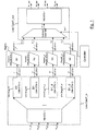
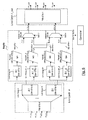
- Fig.1 it shows a network element for a telecommunication network carrying digital signals according to time division multiplexing (TDM) and, more specifically, according to standard Sonet.
- the network element includes four input ports (indicated with P1_in, P2_in, P3_in, P4_in), an input line card (indicated with "Line Card1_in”) connected to the input ports and a plurality of switching planes (indicated with "PlaneA1”, “PlaneB1”, “PlaneA1_d”, “PlaneB1_d”) for performing cross-connections of digital signals.
- Each input port is adapted to receive a digital signal having a bit rate of about 10 Gbit/s, which includes 192 STS-1 frames (or another multiplexed signal of the Sonet standard having a bit rate equivalent to the bit rate of 192 STS-1 frames), each STS-1 frame having a bit rate of about 52 Mbit/s,
- the input line card receives the signals from the input ports and generates therefrom a total of 768 STS-1 input flows (previously indicated with "logical” input flows), which are arranged into 2 first groups (indicated with "A1" and "B1"), each one including 384 STS-1 input flows: A1 includes STS-1 input flows from number 1 to number 384 and A2 includes STS-1 input flows from number 385 to number 768.
- each switching plane is able to switch 384 STS-1, the total input flows are 768 STS-1 and thus the input flows are arranged into 2 first groups, each one including 384 STS-1 input flows.
- the first groups of flows are duplicated into corresponding copies: group A1 is duplicated into group indicated with A1_d and group B1 is duplicated into group indicated with B1_d, thus achieving 4 second groups of flows, indicated with "Link Group A1" including first group A1, "Link Group B1” including first group By, "Link Group A1_d” including first group A1_d, and "Link Group B1_d” including first group B1_d.
- Line Card1_in generates four outputs indicated with i1, i2, i3, i4: flows of Link Group A1 are carried over i1, flows of Link Group B1 are carried over i2, flows of Link Group A1_d are carried over i3 and flows of Link Group B1_d are carried over i4.
- the generation of the input flows, the arrangement into the first groups of flows, the duplication of the first groups of flows and the arrangement into the second group of flows is performed using one (or more than one) input memory and using means for controlling the write into the memory and the read from the memory.
- the generation of the input flows, the arrangement into the first groups of flows, the duplication of the first groups of flows and the arrangement into the second group of flows of an input line card can be configured in advance, that is before the deployment of the network element in the telecommunication network; alternatevely, it can be configured run-time, that is after the network element is deployed in the network and is active, but before the activation of the input line card.
- Each second group of flows is switched by a different switching plane: Link Group A1 is switched by PlaneA1, Link Group B1 is switched by PlaneB1, Link Group A1_d is switched by PlaneA1_d and Link Group B1_d is switched by PlaneB1_d.
- the network element further includes an output line card (indicated with "Line Card1_out") comprising selecting means (indicated with "Selector1").
- the selecting means include 4 data inputs, one data output (indicated with o1_s) and one selector input (indicated with Sel1) for controlling the selection from the data inputs to the data output.
- the output line card further includes means for associating the data output of the selecting means to the output ports.
- PlaneA1 generates output i1_s carrying 384 STS-1 switched flows and is connected to the first data input of Selector1 of Line Card1_out
- PlaneB1 generates output i2_s carrying 384 STS-1 switched flows and is connected to the second data input of Selector
- PlaneA1_d generates output i3_s carrying 384 STS-1 switched flows and is connected to the third data input of Selector1
- PlaneB1_d generates output i4_s carrying 384 STS-1 switched flows and is connected to the fourth data input of Selector1.
- Selector1 is adapted to receive a total of 1536 STS-1 flows and to select therefrom 768 STS-1 output flows carried over the output o1_s of the selecting means.
- the selection is controlled by control information over the control input Sel1, which is driven by a controller (for example, a microprocessor), calculating the control information from configuration information indicating the cross-connections between STS-1 signals of an input port of the input line card and STS-1 signals of an output port of the output line card.
- a controller for example, a microprocessor
- the network element further includes 4 output ports (indicated with P1_out, P2_out, P3_out and P4_out) connected to the output line card Line Card1_out.
- the selected 768 STS-1 output flows are associated to the 4 output ports: for example, output port P1_out includes the selected output flows from number 1 to number 192, output port P2_out includes the selected output flows from number 193 to number 384, output port P3_out includes the selected output flows from number 385 to number 576, output port P4_out includes the selected output flows from number 577 to number 768.
- Each output port is adapted to transmit a digital signal having a bit rate of about 10 Gbit/s, which includes 192 STS-1 frames (or another multiplexed signal of the Sonet standard having a bit rate equivalent to the bit rate of 192 STS-1 frames).
- Fig.1 shows i1 from Link Group A1 to PlaneA1 and carrying 384 STS-1 signals, wherein i1 is only a logical indication, that is i1 can be 384 links (each link carrying one STS-1 signal) between Link Group A1 and Planet1 (thus between Line Card1_in and the Matrix) or can be less than 384 links (each link carrying more than one STS-1 signal) or more than 384 links. Similar considerations apply to i2 from Link Group B1 to PlaneB1, to i3 from Link Group A1_d to PlaneA1_d and to i4 from Link Group B1_d to PlaneB1_d.
- the invention allows to perform a switching function for cross-connection of 768 STS-1 flows by using 4 switching planes, each one having a smaller switching capacity of 384 STS-1 flows.
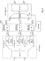
- the network element includes 2 input ports (indicated with P5_in and P6_in), an input line card (indicated with "Line Card2_in”) connected to the input ports and a plurality of switching planes (indicated with "RlaneA2_C2_d", “PlaneB2_A2_d” and "PlaneC2_B2_d") for performing the cross-connections of digital signals.
- Each input port is adapted to receive a digital signal having a bit rate of about 10 Gbit/s, which includes 192 STS-1 frames (or another multiplexed signal of the Sonet standard having a bit rate equivalent to the bit rate of 192 STS-1 frames).
- the input line card receives the signals from the input ports and generates therefrom a total of 384 STS-1 input flows (also indicated with “logical” input flows), which are arranged into 3 first groups (indicated with “A2", “B2” and “C2"), each one including 128 STS-1 input flows: A2 includes STS-1 input flows from number 1 to number 128, B2 includes STS-1 input flows from number 129 to number 256 and C2 includes STS-1 input flows from number 257 to number 384.
- A2 includes STS-1 input flows from number 1 to number 128, B2 includes STS-1 input flows from number 129 to number 256 and C2 includes STS-1 input flows from number 257 to number 384.
- each switching plane is able to crossconnect 256 STS-1
- the total input flows are 384 STS-1 and thus the input flows are arranged into a plurality of first groups such that each first group can be switched by one switching plane: in this second embodiment, the input flows are arranged into 3 first groups, each one including 128 STS-1 input flows, which can be switched by one switching plane able to crossconnect 256 STS-1.
- the first group B2 includes input flows generated from different input ports, because it includes 64 input flows from input port P5_in and 64 input flows from input port P6_in.
- the first groups of flows are duplicated into corresponding copies: group A2 is duplicated into group indicated with A2_d, group B2 is duplicated into group indicated with B2_d and group C2 is duplicated into group indicated with C2_d, thus achieving 6 groups of flows.
- the first groups of flows and the corresponding copies are arranged into 3 second groups of flows, indicated with "Link Group A2_C2_d", “Link Group B2_A2_d” and “Link Group C2_B2_d”, according to the following rules:
- the generation of the input flows, the arrangement into the first groups of flows, the duplication of the first groups of flows and the arrangement into the second group of flows is performed using one (or more than one) input memory and using means for controlling the write into the memory and the read from the memory.
- Each second group of flows is switched by a different switching plane: Link Group A2_C2_d is switched by PlaneA2_C2_d, Link Group B2_A2_d is switched by PlaneB2_A2_d and Link Group C2_B2_dis switched by PlaneC2_B2_d
- the network element further includes an output line card (indicated with "Line Card2_out") comprising selecting means (indicated with "Selector2").
- the selecting means include 3 data inputs, one data output (indicated with o2_s) and one selector input (indicated with Sel2) for controlling the selection from the data inputs to the data output.
- the output line card further includes means for associating the data output of the selecting means to the output ports.
- PlaneA2_C2_d generates output i5_s carrying 384 STS-1 switched flows and is connected to the first data input of Selector2 of Line Card2_out
- PlaneB2_A2_d generates output i6_s carrying 384 STS-1 switched flows and is connected to the second data input of Selector2
- PlaneC2_B2_d generates output i7_s carrying 384 STS-1 switched flows and is connected to the third data input of Selector2.
- Selector2 is adapted to receive a total of 768 STS-1 flaws and to select therefrom 384 STS-1 output flows carried over the output o2_s of the selecting means.
- the selection is controlled by control information over the control input Sel2, which is driven by a controller, calculating the control information from configuration information indicating the cross-connections between STS-1 signals of an input port of the input line card and STS-1 signals of an output port of the output line card.
- the network element further includes 2 output ports (indicated with P5_out and P6_out) connected to the output line card Line Card2_out.
- the selected 384 STS-1 output flows are associated to the 2 output ports: for example, output port P5_out includes the selected output flows from number 1 to number 192, and output port P2_out includes the selected output flows from number 193 to number 384.
- Each output port is adapted to transmit a digital signal having a bit rate of abort 10 Gbit/s, which includes 192 STS-1 frames (or another multiplexed signal of the Sonet standard having a bit rate equivalent to the bit rate of 192 STS-1 frames).
- the invention allows to perform a switching function for cross-connection of 384 STS-1 flows by using 3 switching planes, each one having a smaller cross-connection capability of 256 STS-1 flows.
- Fig.1 and Fig.2 show a plurality of switching planes, wherein each switching plane can include one fabric switch for performing the cross-connections (384 STS-1 in the first embodiment or 256 STS-1 in the second embodiment) of the switching plane: this is shown in Fig.1 wherein PlaneA1 includes one fabric switch indicated with "M1", PlaneB1 includes one fabric switch indicated with "M2", PlaneA1_d includes one fabric switch indicated with "M3” and PlaneB1_d includes one fabric switch indicated with "M4", and it's shown in Fig.2 wherein PlaneA2_C2_d includes one fabric switch indicated with "M5", PlaneB2_A2_d includes one fabric switch indicated with "M6” and PlaneC2_B2_d includes one fabric switch indicated with "M7". Alternatevely, each switching plane can include more than one fabric switch for performing the cross-connections, that is M1 ... M7 indicates a logical switching function (and not a physical fabric switch) which is implemented over
- the switching function of one switching plane is performed over a plurality of fabric switches according to slicing of the flows of the second groups.
- PlaneA1 of the first embodiment performs the cross-connection of 384 STS-1 flows of Link Group A1 by slicing the 384 STS-1 flows over 4 fabric switches, each one for cross-connecting 2 bits of every byte of all the 384 STS-1 flows. Similar considerations apply to PlaneB1 for Link Group B1, to PlaneA1_d for Link Group A1_d and to PlaneB1_d for Link Group B1_d.
- PlaneA2_C2_d of the second embodiment performing the cross-connection of 256 STS-1 flows of Link Group A2_C2_d by slicing the 256 STS-1 flows over 3 fabric switches, each one for cross-connecting 1/3 of the bandwidth of all the 256 STS-1 flows. Similar considerations apply to PlaneB2_A2_d for Link Group B2_A2_d and to PlaneC2_B2_d for Link Group C2_B2_d.
- the plurality of switching planes can be implemented through different matrix boards or through the same matrix board (like shown in Fig.1 and Fig.2 ).
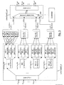
- the network element includes twelve input ports (indicated with P7_in, P8_in, .... P18_in), an input line card (indicated with "Line Card3_in") connected to the input ports and a plurality of fabric switches (indicated with M8, M9, ... M23) for performing the cross-connections.
- Each input port is adapted to receive a digital signal having a bit rate of about 10 Gbit/s, which includes 192 STS-1 frames (or another multiplexed signal of the Sonet standard having a bit rate equivalent to the bit rate of 192 STS-1 frames), each STS-1 frame having a bit rate of about 52 Mbit/s.
- the input line card receives the signals from the input ports and generates therefrom a total of 2304 STS-1 input flows (also indicated with “logical” input flows), which are arranged into 2 first groups (indicated with "A3" and "B3"), each one including 1152 STS-1 input flows: A3 includes STS-1 input flows from number 1 to number 1152 and B3 includes STS-1 input flows from number 1153 to number 2304.
- the first groups of flows are duplicated into corresponding copies: group A3 is duplicated into group indicated with A3_d and group B3 is duplicated into group indicated with B3_d, thus achieving 4 second groups of flows, indicated with "Link Group A3” including first group A3, “Link Group B3” including first group B3, “Link Group A3_d” including first group A3_d, and "Link Group B3_d” including first group B3_d.
- Each second group of flows includes 1152 STS-1 flows which can't be switched by one of the fabric switches, which are adapted to switch 384 STS-1 flows. Therefore each second group is further divided into three third groups of flows, each third group including 384 flows. Specifically:
- Each third group is cross-connected over 4 fabric switches according to the slicing of the flows.
- each flow is divided into 4 slices: the first slice is cross-connected by fabric switch M8, the second slice is cross-connected by fabric switch M9, the third slice is cross-connected by fabric switch M10 and the fourth slice is cross-connected by fabric switch M11. This is indicated in Fig.3 with continuous arrows from A3.1 to M8, M9, M10 and M11.
- the network element further includes an output line card (indicated with "Line Card3_out") comprising selecting means (indicated with "Selector3").
- the selecting means include 3 data inputs (indicated with i8_s, i9_s, i10_s, i11_s), one data output (indicated with o3_s) and one selector input (indicated with Sel3) for controlling the selection from the data inputs to the data output.
- the output line card further includes means for associating the data output of the selecting means to the output ports.
- the first input i8_s is adapted to receive 1152 STS-1 flows switched by fabric switches M8, M9, M10, M11
- the second input i9_s is adapted to receive 1152 STS-1 flows switched by fabric switches M12, M13, M 14, M15
- the third input i10_s is adapted to receive 1152 STS-1 flows switched by fabric switches M16, M17, M18, M19
- the fourth input i11_s is adapted to receive 1152 STS-1 flow switched by fabric switches M20, M21, M22, M23.
- the selecting means are adapted to receive a total of 4608 STS-1 flows and to select therefrom 2304 STS-1 output flows carried over the output o3_s of the selecting means.
- the selection is controlled by control information over the control input Sel3, which is driven by a controller, calculating the control information from configuration information indicating the cross-connections between STS-1 signals of an input port of the input line card and STS-1 signals of an output port of the output line card.
- the network element further includes 12 output ports (indicated with P7_out, P8_out, ... P18_out) connected to the output line card Line Card3_out.
- the selected 2304 STS-1 output flows are associated to the 12 output ports, each one adapted to transmit a digital signal having a bit rate of about 10 Gbit/s, which includes 192 STS-1 frames (or another multiplexed signal of the Sonet standard having a bit rate equivalent to the bit rate of 192 STS-1 frames).
- the invention allows to perform a switching function for cross-connection of 2304 STS-1 flows by using 16 fabric switches, each one having a smaller switching capacity of 384 STS-1 flows.
- the third embodiment allows to perform a switching function (2304 x 2304 STS-1) higher than in the first embodiment (768 x 768 STS-1), by using smaller fabric switches of the same switching capacity (384 x 384 STS-1).
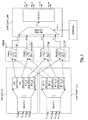
- Fig.4 shows a network element according to a fourth embodiment of the invention, which is a modification of the first embodiment.
- Fig.4 shows a network element including the input line card "Line Card1_in” of the first embodiment and further including another input line card (indicated with "Line Card1.1_in”).
- other first and second group of flows are generated from the input flows received at the other Line Card1.1_in, like explained for the input flows received at Line Card1 of the first embodiment.
- the other second group of flows generated from Line Card1.1_in are switched by the switching planes PlaneA1, PlaneB1, PlaneA1_d and PlaneB1_d, like explained for the second group of flows generated from Line Card1_in of the first embodiment.
- PlaneA1 generates output i1_s carrying 384 STS-1 switched flows and is connected to the first input of Selector1 of Line Card1_out, wherein the 384 STS-1 switched flows can come both from the STS-1 signals of Link Group A1 of Line Card1_in and from the STS-1 signals of Link Group A1 of Line Card1.1_in.
- PlaneB1 generates output i2_s carrying 384 STS-1 switched flows and is connected to the second input of Selector1, wherein the 384 STS-1 switched flows can come both from the STS-1 signals of Link Group B1 of Line Card1_in and from the STS-1 signals of Link Group B1 of Line Card1.1_in.
- PlaneA1_d generates output i3_s carrying 384 STS-1 switched flows and is connected to the third input of Selector1, wherein the 384 STS-1 flows can come both from the STS-1 signals of Link Group A1_d of Line Card1_in and from the STS-1 signals of Link Group A1_d of Line Card1.1_in
- PlaneB1_d generates output i4_s carrying 384 STS-1 switched flows and is connected to the fourth input of Selector1, wherein the 384 STS-1 flows can come both from the STS-1 signals of Link Group B1_d of Line Card1_in and from the STS-1 signals of Link Group B1_d of Line Card1.1_in.
- PlaneA1 further generates output i1.1_s carrying 384. STS-1 switched flows and is connected to the first input of the selector of another output line card (not shown in Fig.4 ). PlaneB1 further generates output i2.1_s carrying 384 STS-1 switched flows and is connected to the second input of the selector of the other output line card. PlaneA1_d further generates output i3.1_s carrying 384 STS-1 switched flows and is connected to the third input of the selector of the other output line card. PlaneB1_d further generates output i4.1_s carrying 384 STS-1 switched flows and is connected to the fourth input of the selector of the other output line card.
- Selector1 is adapted to receive a total of 1536 STS-1 flows and to select therefrom 768 STS-1 output flows carried over the output o1_s of the selecting means.
- the selection is controlled by control information over the control input Sel1.1 which is driven by a controller, calculating the control information from configuration information indicating the cross-connections between STS-1 signals of an input port of the input line cards and STS-1 signals of an output port of the output line card.
- the switching planes PlaneA1. PlaneB1, PlaneA1_d and PlaneB1_d are adapted to receive second group of flows from all the input line cards (for example, from 64 input line cards) and to switch the received flows; selecting means are adapted to select the switched flows from the switching planes, thus achieving the cross-connections between signals of any input port of any input line card and signals of any output port of the output line card.
- the overall switching system which includes the input line cards, the plurality of fabric switches and the output line cards, is equivalent to one switching function, thus there are no limitations of the cross-connections between the inputs and the outputs (for example, multicast can be performed).
- the switching planes PlaneA1, PlaneB1, PlaneA1_d, PlaneB1_d are implemented through one matrix board and the Controller is implemented over this matrix board, such that the Controller (indicated with "central” Controller) generates centrally the control information for the selecting means of a plurality of output line cards.
- Fig.5 it shows more in detail the method for performing the selection in the selecting means (Selector1) of the first embodiment of Fig.1 .
- the fabric switches indicated in Fig.1 with M1, M2, M3, M4 are implemented through memories indicated in Fig.5 with MemA1, MemB1, MemA1_d and MemB1_d respectively. Therefore the matrix board includes memory MemA1 for storing the flows of Link Group A1, MemB1 for storing the flows of Link Group B1, MemA1_d for storing the flows of Link Group A1__d and MemB1_d for storing the flows of Link Group B1_d.
- the matrix board further includes four address generators (indicated with “Address generator1 ", “Address generator2”; “Address generator3” and “Address generator4") generating the addresses values for reading data from MemA1, MemB1, MemA1_d and MemB1_d respectively.
- MemA1 is storing data a_J0 at address a0, data a_J2 at address a2, .... data a_J766 at address a766.
- MemB1 is storing data b_J0 at address b0, data b_J2 at address b2, .. data b_J766 at address b766.
- MemA1_d is storing data a_J1 at address a1, data a_J3 at address a3, ... data a_J757 at address a767.
- MemB1_d is storing data b_J1 at address b1, data b_J3 at address b3, ... data b_J767 at address b767.
- the selecting means incudes a first selector (indicated with “Selector1.1”) for selecting data read from memory MemA1 or from memory MemB1, includes a second selector (indicated with “Sefector1.2”) for selecting data read from memory MemA1_d or from memory MemB1_d and includes a converter from parallel to serial (indicated with "P/S Converter”) for receiving data from the outputs i1.2_s, i3.4_s of the two selectors and for generating therefrom a serial data stream over o1_s.
- the first selector Selector1.1 further includes one control input (indicated with "Sel1.1") which is driven by the Controller and the second selector Seleetor1.2 further includes one control input (indicated with "Sel1.2”) which is driven by the Controller.
- the Controller generates a sequence of addresses indicated with J0, J1, J2, .. J767 having length equal to the number of the STS-1 output flows (768) carried over o1_s, wherein address J0 corresponds to STS-1 output flow #0, address J1 corresponds to STS-1 output flow #1, ... address J767 corresponds to STS-1 output flow #767.
- 768 STS-1 output flows carried over o1_s are selected from the 1536 flows carried over i1_s, i2_s, i3_s; i4_s, according to the following rule.
- output flows having an even number (0, 2, 4, .., 766) are read from MemA1 or MemB1, while output flows having an odd number (1, 3, 5, ..., 767) are read from MemA1_d or MemB1_d.
- Controlled generates an address sequence indicated with J0, J1, J2, ...
- Address generator1 receivers as input the address sequence J0, J2, J4, ... J766 and generates as output the address sequence a0, a2, a4, ..., a766 respectively, wherein and, a2, a4, ..., a766 are the addresses of MemA1 storing the data received from Link Group A1.
- Address generator2. receives as input the address sequence J0, J2, J4, ... J766 and generates as output the address sequence b0, b2, b4, ..., b766 respectively, wherein b0, b2, b4, ..., b766 are the addresses of MemB1 storing the data received from Link Group B1.
- Address generator3 receives as input the address sequence J1, J3, J5, ... J767 and generates as output the address sequence a1, a3, a5, ..., a761 respectively, wherein a1, a3, a5, ..., a767 are the addresses of MemA1_d storing the data received from Link Group A1_d.
- Address generator4 receives as input the address sequence J1, J3, J5, ... J767 and generates as output the address sequence b0, b2, b4, ..., b766 respectively, wherein b0, b2, b4, ..., b767 are the addresses of MemB1_d storing the data received from Link Group B1_d.
- STS-1 input flows are cross-connected to the STS-1 output flows such that STS-1 output flow #1 carries data a_J0 stored into MemA1, STS-1 output flow #2 carries data a_J1 stored into MemA1_d.
- STS-1 output flow #3 carries data b_J2 stored into MemB1
- STS-1 output flow #4 carries data a_J3 stored into MemA1_d
- STS-1 output flow #5 carries data a_J4 stored into MemA1
- STS-1 output flow #6 carries b_J5 stored into MemB1_d, ....
- Controller and the Address generator1 , 2, 3, 4 generate the following values for the control inputs Sel1.1 and Sel1.2;
- the output i1.2_s of the first selector (elector1.1) carries the data sequence a_J0, b_J2, a_J4,... and the output i3.4_s of the second selector (elector1.2) carries the data sequence a_J1, a_J3, b_J5, ....
- the output of the first and second selector is connected to the two inputs of a parallel to serial converter, which reads alternatevely the data from the two inputs and transmits the data read from the inputs to the output o1_s.
- the above method for performing the selection can be extended to the switching between a plurality of input ports and a plurality of output ports, wherein the ports can carry a plurality of signals.
- Fig.4 it shows the switching between two input line cards (8 input ports) and one output line card (4 output ports).
- the memory MemA1 further stores the flows of Link Group A1 of Line Card1.1_in.
- MemB1 further stores the flows of Link Group B1 of Line Card1.1_in
- MemA1_d further stores the flows of Link Group B1 of Line Card1.1_in
- MemB1_d further stores the flows of Link Group B1_d of Line Card1.1_in:
- Address generator1 further receives an information for identifying the input line card, in order to generate to the output the address sequence addr1 including the values for reading the stored data received from Link Group A1 of Line Card1_in or from Link Group A1 of Line Card1.1_in.
- Address generator2 further receives the information for identifying the input line card, in order to generate to the output the address sequence addr2 including the values for reading the stored data received from Link Group B1 of Line Card1_in or from Link Group B1 of Line Card1.1_in.
- Address generator3 further receives the information for identifying the input line card, in order to generate to the output the address sequence addr3 including the values for reading the stored data received from Link Group A1_d of Line Card1_in or from Link Group A1_d of Line Card1.1_in.
- Address generator4 further receives the information for identifying the input line card, in order to generate to the output the address sequence addr4 including the values for reading the stored data received from Link Group B1_d of Line Card1_in or from Link Group B1_d of Line Card1.1_in.
- the matrix board includes a plurality of memories storing the data of the flows of the second groups and the rule for reading from the memories depends on the arrangement of the input flows into the first groups.
- the input flows are arranged into two first groups and thus the address sequence J0, J1, .... is divided into two groups, the first one including the even numbers (J0, J2, J4, .., J766) and the second one including the odd numbers (J1, J3, J5, ..., J767).
- This division between even and odd number is only a preferred solution and other solutions are possible.
- the first group of the addresses sequence can include the numbers J0, J1, J4, J5, J8, J9 and the second group the numbers J2, J3, J6, J7, J10, J11, ....
- the input flows are arranged into three first groups and thus the address sequence J0, J1, .... is divided into three groups.
- the first group includes the numbers J0, J3, J6, ...
- the second group includes the numbers J1, J4, J7, ....
- the third group includes the numbers J2, J5, J8, ...
- control information is distributed by the central Controller only to the output line cards, while the input line cards are blind to this control information.
- the duplication of the first groups into corresponding copies is performed in the input line card (preferably, at the transmission side) and the selection of the switched flows is performed in the output line card (preferably, at the reception side), but other solutions are possible, like explained for the fifth embodiment.
- Fig.6 it shows a network element according to a fifth embodiment of the invention, which is a modification of the first, second, third and fourth embodiments.
- the duplication of the first groups into corresponding copies is performed in the matrix board (preferably, at the reception side) and the selection of the switched flows is performed in the matrix board (preferably, at the transmission side).
- the arrangement into the first and second group of flows is performed like in the first embodiment, that is the 768 STS-1 input flows are arranged into first groups A1 and B1 each one including 384 STS-1 flows, the first groups A1, B1 are duplicated into A1_d, B1__d respectively and the second groups includes A1, A1_d, B1, B1_d.
- Fig.6 shows that the duplication of A1 into A1_d is performed in the matrix board and that the duplication of B1 into B1_d is performed in the matrix board.
- Fig.6 further shows that the selection of the switched flows is performed by a first selector (indicated with “Selector1.3”) and by a second selector (indicated with “Selector1.4”) which are placed in the matrix board: Selector1.3 receives the flows switched by PlaneA1 and PlaneB1, while Selector1.4 receives the flows switched by PlaneA1_d and PlaneB1_d.
- selector1.3 receives the flows switched by PlaneA1 and PlaneB1
- Selector1.4 receives the flows switched by PlaneA1_d and PlaneB1_d.
- the fifth embodiment has the advantage (respect to the first embodiment) to require less bandwidth (thus less links) between the input line card and the matrix board and between the matrix board and the output line card.
- the bandwidth required between the input line card (or the output line card) and the matrix board of the fifth embodiment is equivalent to the bandwidth of 768 STS-1
- the bandwidth required between the input line card (or the output line card) and the matrix board of the first embodiment is equivalent to the bandwidth of 1536 STS-1: therefore, in this example, the bandwidth required by the fifth embodiment is half of the bandwidth required by the first embodiment.
- the input flows carry digital signals according to Time Division Multiplexing
- the input flows carry digital signals arranged into data packets; in this case, the configuration information received by the Controller is generated dynamically and depends on the content of one (or more) field carried in the data packets.
- the method can be advantageously implemented on a network element of an optical telecommunications network, the network element including hardware devices like an Application Specific integrated Circuit (ASIC), a Field Programmable Gate Array (FPGA), an Electrically Programmable Logical Device (EPLD) or a microprocessor.
- ASIC Application Specific integrated Circuit
- FPGA Field Programmable Gate Array
- EPLD Electrically Programmable Logical Device
- the method for controlling the selection in the selecting means of the first, second, third, fourth and fifth embodiments is implemented through a software program like Very high speed integrated circuit Hardware Description Language (VHDL) or Verilog, wherein the software program is running on hardware devices in the network element like an ASIC, a FPGA or an EPLD; alternatively, the method is implemented through a software program like C language running on a microprocessor (external or embedded into an FPGA) in the network element.
- VHDL Very high speed integrated circuit Hardware Description Language
- Verilog Verilog
- Fig.1 shows an input line card ("Line Card1_in”) and another output line card (“Line Card1_out”).
- an input/output line card includes the input line card and the output line card. Similar considerations apply to Fig.2 , 3 , 4 and 6 .
Landscapes
- Engineering & Computer Science (AREA)
- Computer Networks & Wireless Communication (AREA)
- Signal Processing (AREA)
- Computer Security & Cryptography (AREA)
- Data Exchanges In Wide-Area Networks (AREA)
- Mobile Radio Communication Systems (AREA)
- Use Of Switch Circuits For Exchanges And Methods Of Control Of Multiplex Exchanges (AREA)
- Electronic Switches (AREA)
Claims (22)
- Verfahren für die Vermittlung von Digitalsignalen, die folgenden Schritte umfassend:- Erzeugen von mehrfachen Eingangsflüssen von mehrfachen Eingängen, wobei die Anzahl der mehrfachen Eingangsflüsse höher ist als die Anzahl der mehrfachen Eingänge;- Einteilen der mehrfachen Eingangsflüsse in mehrfache erste Gruppen (A1, B1) von Flüssen unter Berücksichtigung der Vermittlungskapazität von mindestens zwei Koppelfeldern, wobei die Anzahl der von einem jeden der mindestens zwei Koppelfelder vermittelten Flüsse niedriger ist als die Anzahl der mehrfachen Eingangsflüsse;- Duplizieren der mehrfachen ersten Gruppen von Flüssen in mindestens eine entsprechende Kopie (A1_d, B1_d),- Einteilen der mehrfachen ersten Gruppen und der mindestens einen entsprechenden Kopie in mehrfache zweite Gruppen (Link Group A1, Link Group B1 , Link Group A1_d, Link Group B1_d) von Flüssen;- Vermitteln der Flüsse der mehrfachen zweiten Gruppen an die mindestens zwei Koppelfelder;- Auswählen von mehrfachen Ausgangsflüssen (o1_s) aus mindestens einem Teil der vermittelten Flüsse der mehrfachen zweiten Gruppen.
- Verfahren nach Anspruch 1, wobei die mehrfachen ersten Gruppen (A1, B1) und die Kopien (A1_d, B1_d) in verschiedene mehrfache zweite Gruppen (Link Group A1, Link Group B1, Link Group A1_d, Link Group B1_d) eingeteilt werden.
- Verfahren nach einem beliebigen der vorstehenden Ansprüche, wobei das Einteilen in die mehrfachen zweiten Gruppen derart erfolgt, dass zumindest eine zweite Gruppe (Link Group A2_C2_d) eine Gruppe (A2) aus den mehrfachen ersten Gruppen sowie die Kopie (C2_d) einer anderen Gruppe (C2) aus den mehrfachen ersten Gruppen umfasst.
- Verfahren nach Anspruch 1, weiterhin die folgenden Schritte umfassend:- Aufteilen mindestens einer der zweiten Gruppen von Flüssen in mehrfache dritte Gruppen (A3.1, A3.2, A3.3) von Flüssen;- Zerlegen der Flüsse der dritten Gruppen über die mindestens zwei Koppelfelder.
- Verfahren nach einem beliebigen der vorstehenden Ansprüche, wobei die mindestens zwei Koppelfelder in mehrfache Vermittlungsebenen eingeteilt sind, und wobei das Vermitteln der mehrfachen zweiten Gruppen an verschiedene Vermittlungsebenen erfolgt.
- Verfahren nach einem beliebigen der vorstehenden Ansprüche, wobei die mehrfachen Eingänge mehrfache Eingangsports sind und eine Gruppe der mehrfachen ersten Gruppen die von verschiedenen Eingangsports erzeugten Eingangsflüsse umfasst.
- Verfahren nach Anspruch 5 oder 6, wobei eine der mehrfachen Vermittlungsebenen eine Vielzahl von Koppelfeldern umfasst, wobei das Verfahren weiterhin den Schritt des Zerlegens der Flüsse einer Gruppe der mehrfachen zweiten Gruppen umfasst, wobei der Schritt des Vermittelns der Flüsse der Gruppe das Vermitteln der zerlegten Flüsse über die Vielzahl von Koppelfeldern umfasst.
- Verfahren nach einem beliebigen der vorstehenden Ansprüche, wobei die mehrfachen Eingänge mehrfache Eingangsports sind, und wobei eine erste Eingangs-Line-Card dazu ausgelegt ist, die mehrfachen ersten Eingangsports aufzunehmen, wobei eine Matrixleiterplatte die mindestens zwei Koppelfelder enthält, und wobei eine Ausgangs-Line-Card dazu ausgelegt ist, die mehrfachen Ausgangsports zu erzeugen.
- Verfahren nach Anspruch 8, wobei der Schritt des Duplizierens an der Übertragungsseite der ersten Eingangs-Line-Card ausgeführt wird.
- Verfahren nach Anspruch 9, wobei der Schritt des Auswählens an der Empfangsseite der Ausgangs-Line-Card ausgeführt wird.
- Verfahren nach Anspruch 8, wobei der Schritt des Duplizierens an der Empfangsseite der Matrixleiterplatte und der Schritt des Auswählens an der Übertragungsseite der Matrixleiterplatte ausgeführt werden.
- Verfahren nach einem beliebigen der Ansprüche 8 bis 11, wobei der Schritt des Einteilens der mehrfachen Eingangsflüsse weiterhin die Kapazität der Links zwischen der Eingangs-Line-Card und der Matrixleiterplatte berücksichtigt.
- Verfahren nach einem beliebigen der Ansprüche 8 bis 12, wobei das Verfahren weiterhin die folgenden Schritte umfasst:- Erzeugen, in der Matrixleiterplatte, von Steuerdaten aus den Konfigurationsdaten, welche die Kreuzverbindungen zwischen den mehrfachen Eingangsflüssen und den mehrfachen Ausgangsflüssen anzeigen;- Übertragen der Steuerdaten von der Matrixleiterplatte an die Ausgangs-Line-Card;- Empfangen der Steuerdaten an der Ausgangs-Line-Card, und Ausführen der Wahl der mehrfachen Ausgangsflüsse daraus.
- Verfahren nach einem beliebigen der vorstehenden Ansprüche, weiterhin die folgenden Schritte umfassend:- Erzeugen von weiteren mehrfachen Eingangsflüssen von weiteren mehrfachen Eingängen, wobei die Anzahl der weiteren mehrfachen Eingangsflüsse höher ist als die Anzahl der weiteren mehrfachen Eingänge;- Einteilen der weiteren mehrfachen Eingangsflüsse in weitere mehrfache erste Gruppen (A1.1, B1,1) von Flüssen unter Berücksichtigung der Vermittlungskapazität der mindestens zwei Koppelfelder;- Duplizieren der weiteren mehrfachen ersten Gruppen von Flüssen in mindestens eine weitere entsprechende Kopie (A1.1_d, B1.1_d);- Einteilen der weiteren mehrfachen ersten Gruppen und der mindestens einen weiteren entsprechenden Kopie in weitere mehrfache zweite Gruppen;- Vermitteln der Flüsse der weiteren mehrfachen zweiten Gruppen an die mindestens zwei Koppelfelder;- Auswählen der mehrfachen Ausgangsflüsse aus mindestens dem Teil der vermittelten Flüsse der mehrfachen zweiten Gruppen und aus mindestens einem Teil von vermittelten Flüssen der weiteren mehrfachen zweiten Gruppen.
- Vorrichtung, dazu ausgelegt, auf mindestens zwei Koppelfelder zuzugreifen, um digitale Signale zu vermitteln, wobei die Vorrichtung umfasst:- Erste Mittel zum:• Erzeugen von mehrfachen Eingangsflüssen von mehrfachen Eingängen, wobei die Anzahl der mehrfachen Eingangsflüsse höher ist als die Anzahl der mehrfachen Eingänge;• Einteilen der mehrfachen Eingangsflüsse in mehrfache erste Gruppen (A1, B1) von Flüssen unter Berücksichtigung der Vermittlungskapazität von mindestens zwei Koppelfeldern; wobei die Anzahl der von einem jeden der mindestens zwei Koppelfelder vermittelten Flüsse niedriger ist als die Anzahl der mehrfachen Eingangsflüsse;• Duplizieren der mehrfachen ersten Gruppen von Flüssen in mindestens eine entsprechende Kopie (A1_d, B1_d);• Einteilen der mehrfachen ersten Gruppen und der mindestens einen entsprechenden Kopie in mehrfache zweite Gruppen (Link Group A1, Link Group B1, Link Group A1_d, Link Group B1_d) von von den mindestens zwei Koppelfeldern zu vermittelnden Flüssen;- zweite Mittel (Selector1) zum Auswählen von mehrfachen Ausgangsflüssen aus von den mindestens zwei Koppelfeldern vermittelten Flüssen.
- Vorrichtung nach Anspruch 15, wobei die mehrfachen Eingänge mehrfache Eingangsports sind, und wobei eine erste Eingangs-Line-Card (Line Card1_in) für die Aufnahme der mehrfachen ersten Eingangsports ausgelegt ist.
- System zur Vermittlung von digitalen Signalen, wobei das System eine Vorrichtung nach Anspruch 15 oder 16 sowie die mindestens zwei Koppelfelder umfasst.
- System nach Anspruch 17, wobei das System eine Matrixleiterplatte mit den mindestens zwei Koppelfeldern umfasst, wobei das erste Mittel weiterhin für die Berücksichtigung der Kapazität der Links zwischen der Eingangs-Line-Card und der Matrixleiterplatte ausgelegt ist.
- System nach Anspruch 17, wobei das System Steuermittel umfasst, die für den Empfang von Konfigurationsdaten, welche die Kreuzverbindungen zwischen den mehrfachen Eingangsflüssen und den mehrfachen Ausgangsflüssen anzeigen, sowie für das Erzeugen von Informationen zum Steuern der Auswahlmittel ausgelegt sind.
- Netzwerkelement mit einem System nach einem beliebigen der Ansprüche 17 bis 19.
- Telekommunikationsnetzwerk mit mindestens einem Netzwerkelement nach Anspruch 20.
- Computerprogramm mit Computerprogrammecode-Mitteln, welche für das Ausführen der Schritte des Verfahrens nach Anspruch 13 ausgelegt sind, wenn das besagte Computerprogramm auf einer Hardware eines Netzwerkelements läuft.
Priority Applications (3)
| Application Number | Priority Date | Filing Date | Title |
|---|---|---|---|
| DE602008001053T DE602008001053D1 (de) | 2008-02-22 | 2008-02-22 | Verfahren für den Zugriff auf mehrere Koppelfelder |
| AT08300108T ATE465601T1 (de) | 2008-02-22 | 2008-02-22 | Verfahren für den zugriff auf mehrere koppelfelder |
| EP08300108A EP2094022B1 (de) | 2008-02-22 | 2008-02-22 | Verfahren für den Zugriff auf mehrere Koppelfelder |
Applications Claiming Priority (1)
| Application Number | Priority Date | Filing Date | Title |
|---|---|---|---|
| EP08300108A EP2094022B1 (de) | 2008-02-22 | 2008-02-22 | Verfahren für den Zugriff auf mehrere Koppelfelder |
Publications (2)
| Publication Number | Publication Date |
|---|---|
| EP2094022A1 EP2094022A1 (de) | 2009-08-26 |
| EP2094022B1 true EP2094022B1 (de) | 2010-04-21 |
Family
ID=39619230
Family Applications (1)
| Application Number | Title | Priority Date | Filing Date |
|---|---|---|---|
| EP08300108A Not-in-force EP2094022B1 (de) | 2008-02-22 | 2008-02-22 | Verfahren für den Zugriff auf mehrere Koppelfelder |
Country Status (3)
| Country | Link |
|---|---|
| EP (1) | EP2094022B1 (de) |
| AT (1) | ATE465601T1 (de) |
| DE (1) | DE602008001053D1 (de) |
Family Cites Families (2)
| Publication number | Priority date | Publication date | Assignee | Title |
|---|---|---|---|---|
| IT1272471B (it) * | 1993-05-17 | 1997-06-23 | Italtel Spa | Metodo ed unita' per la ricomposizione in un unico flusso di due o piu' flussi ridondati di celle uscenti da reti di connessione ridondate di un sistema di telecomunicazioni atm |
| US6894970B1 (en) * | 2000-10-31 | 2005-05-17 | Chiaro Networks, Ltd. | Router switch fabric protection using forward error correction |
-
2008
- 2008-02-22 EP EP08300108A patent/EP2094022B1/de not_active Not-in-force
- 2008-02-22 AT AT08300108T patent/ATE465601T1/de not_active IP Right Cessation
- 2008-02-22 DE DE602008001053T patent/DE602008001053D1/de active Active
Also Published As
| Publication number | Publication date |
|---|---|
| EP2094022A1 (de) | 2009-08-26 |
| ATE465601T1 (de) | 2010-05-15 |
| DE602008001053D1 (de) | 2010-06-02 |
Similar Documents
| Publication | Publication Date | Title |
|---|---|---|
| JP3328780B2 (ja) | 非線形転送モードスイッチング構成 | |
| US7324537B2 (en) | Switching device with asymmetric port speeds | |
| US5014268A (en) | Parallel time slot interchanger matrix and switch block module for use therewith | |
| US5493565A (en) | Grooming device for streamlining a plurality of input signal lines into a grouped set of output signals | |
| EP0607673A2 (de) | ATM-Vermittlungsstelle | |
| US6343075B1 (en) | Rearrangeable switch having a non-power of two number of physical center stages | |
| US20060209899A1 (en) | Switch for integrated telecommunication networks | |
| CA2020015A1 (en) | Frame conversion circuit | |
| US5475383A (en) | Cross-point type switch using common memories | |
| US7068653B2 (en) | Data packet switching node accommodating very high bit rate interfaces | |
| US7042913B2 (en) | Method and system for writing data to memory elements | |
| EP2094022B1 (de) | Verfahren für den Zugriff auf mehrere Koppelfelder | |
| EP1052872B1 (de) | Fehlerschutz für Störungsfreie und Fehlerlose Vermittlung von Fernmeldesignalen | |
| JP3300853B2 (ja) | 非線形転送モードスイッチング構成 | |
| US4101737A (en) | Control arrangement in a time-space-time (t-s-t) time division multiple (t.d.m.) telecommunication switching system | |
| US6208641B1 (en) | Switch with one-bit resolution | |
| US4509168A (en) | Digital remote switching unit | |
| JPH11275039A (ja) | タイムスロット・アサインメント回路 | |
| JP3300854B2 (ja) | 非線形転送モードスイッチング構成 | |
| US7978736B2 (en) | Efficient provisioning of a VT/TU cross-connect | |
| JP2937666B2 (ja) | クロスコネクト装置 | |
| US4532624A (en) | Parity checking arrangement for a remote switching unit network | |
| KR0164109B1 (ko) | 동기식 전송시스템에서 시험 액세스를 위한 3 x 6N 교차 스위칭 장치 | |
| US4509169A (en) | Dual rail network for a remote switching unit | |
| CN1113580C (zh) | 在通信交换机中向控制存储器提供控制信息的方法和系统 |
Legal Events
| Date | Code | Title | Description |
|---|---|---|---|
| PUAI | Public reference made under article 153(3) epc to a published international application that has entered the european phase |
Free format text: ORIGINAL CODE: 0009012 |
|
| 17P | Request for examination filed |
Effective date: 20080812 |
|
| AK | Designated contracting states |
Kind code of ref document: A1 Designated state(s): AT BE BG CH CY CZ DE DK EE ES FI FR GB GR HR HU IE IS IT LI LT LU LV MC MT NL NO PL PT RO SE SI SK TR |
|
| AX | Request for extension of the european patent |
Extension state: AL BA MK RS |
|
| GRAP | Despatch of communication of intention to grant a patent |
Free format text: ORIGINAL CODE: EPIDOSNIGR1 |
|
| GRAS | Grant fee paid |
Free format text: ORIGINAL CODE: EPIDOSNIGR3 |
|
| GRAA | (expected) grant |
Free format text: ORIGINAL CODE: 0009210 |
|
| AK | Designated contracting states |
Kind code of ref document: B1 Designated state(s): AT BE BG CH CY CZ DE DK EE ES FI FR GB GR HR HU IE IS IT LI LT LU LV MC MT NL NO PL PT RO SE SI SK TR |
|
| REG | Reference to a national code |
Ref country code: GB Ref legal event code: FG4D |
|
| REG | Reference to a national code |
Ref country code: CH Ref legal event code: EP |
|
| AKX | Designation fees paid |
Designated state(s): AT BE BG CH CY CZ DE DK EE ES FI FR GB GR HR HU IE IS IT LI LT LU LV MC MT NL NO PL PT RO SE SI SK TR |
|
| REG | Reference to a national code |
Ref country code: IE Ref legal event code: FG4D |
|
| REF | Corresponds to: |
Ref document number: 602008001053 Country of ref document: DE Date of ref document: 20100602 Kind code of ref document: P |
|
| REG | Reference to a national code |
Ref country code: NL Ref legal event code: VDEP Effective date: 20100421 |
|
| LTIE | Lt: invalidation of european patent or patent extension |
Effective date: 20100421 |
|
| PG25 | Lapsed in a contracting state [announced via postgrant information from national office to epo] |
Ref country code: NO Free format text: LAPSE BECAUSE OF FAILURE TO SUBMIT A TRANSLATION OF THE DESCRIPTION OR TO PAY THE FEE WITHIN THE PRESCRIBED TIME-LIMIT Effective date: 20100721 Ref country code: SE Free format text: LAPSE BECAUSE OF FAILURE TO SUBMIT A TRANSLATION OF THE DESCRIPTION OR TO PAY THE FEE WITHIN THE PRESCRIBED TIME-LIMIT Effective date: 20100421 Ref country code: NL Free format text: LAPSE BECAUSE OF FAILURE TO SUBMIT A TRANSLATION OF THE DESCRIPTION OR TO PAY THE FEE WITHIN THE PRESCRIBED TIME-LIMIT Effective date: 20100421 Ref country code: LT Free format text: LAPSE BECAUSE OF FAILURE TO SUBMIT A TRANSLATION OF THE DESCRIPTION OR TO PAY THE FEE WITHIN THE PRESCRIBED TIME-LIMIT Effective date: 20100421 Ref country code: ES Free format text: LAPSE BECAUSE OF FAILURE TO SUBMIT A TRANSLATION OF THE DESCRIPTION OR TO PAY THE FEE WITHIN THE PRESCRIBED TIME-LIMIT Effective date: 20100801 |
|
| PG25 | Lapsed in a contracting state [announced via postgrant information from national office to epo] |
Ref country code: IS Free format text: LAPSE BECAUSE OF FAILURE TO SUBMIT A TRANSLATION OF THE DESCRIPTION OR TO PAY THE FEE WITHIN THE PRESCRIBED TIME-LIMIT Effective date: 20100821 Ref country code: LV Free format text: LAPSE BECAUSE OF FAILURE TO SUBMIT A TRANSLATION OF THE DESCRIPTION OR TO PAY THE FEE WITHIN THE PRESCRIBED TIME-LIMIT Effective date: 20100421 Ref country code: SI Free format text: LAPSE BECAUSE OF FAILURE TO SUBMIT A TRANSLATION OF THE DESCRIPTION OR TO PAY THE FEE WITHIN THE PRESCRIBED TIME-LIMIT Effective date: 20100421 Ref country code: FI Free format text: LAPSE BECAUSE OF FAILURE TO SUBMIT A TRANSLATION OF THE DESCRIPTION OR TO PAY THE FEE WITHIN THE PRESCRIBED TIME-LIMIT Effective date: 20100421 Ref country code: AT Free format text: LAPSE BECAUSE OF FAILURE TO SUBMIT A TRANSLATION OF THE DESCRIPTION OR TO PAY THE FEE WITHIN THE PRESCRIBED TIME-LIMIT Effective date: 20100421 Ref country code: HR Free format text: LAPSE BECAUSE OF FAILURE TO SUBMIT A TRANSLATION OF THE DESCRIPTION OR TO PAY THE FEE WITHIN THE PRESCRIBED TIME-LIMIT Effective date: 20100421 |
|
| PG25 | Lapsed in a contracting state [announced via postgrant information from national office to epo] |
Ref country code: PL Free format text: LAPSE BECAUSE OF FAILURE TO SUBMIT A TRANSLATION OF THE DESCRIPTION OR TO PAY THE FEE WITHIN THE PRESCRIBED TIME-LIMIT Effective date: 20100421 Ref country code: CY Free format text: LAPSE BECAUSE OF FAILURE TO SUBMIT A TRANSLATION OF THE DESCRIPTION OR TO PAY THE FEE WITHIN THE PRESCRIBED TIME-LIMIT Effective date: 20100616 |
|
| PG25 | Lapsed in a contracting state [announced via postgrant information from national office to epo] |
Ref country code: DK Free format text: LAPSE BECAUSE OF FAILURE TO SUBMIT A TRANSLATION OF THE DESCRIPTION OR TO PAY THE FEE WITHIN THE PRESCRIBED TIME-LIMIT Effective date: 20100421 Ref country code: EE Free format text: LAPSE BECAUSE OF FAILURE TO SUBMIT A TRANSLATION OF THE DESCRIPTION OR TO PAY THE FEE WITHIN THE PRESCRIBED TIME-LIMIT Effective date: 20100421 |
|
| PLBE | No opposition filed within time limit |
Free format text: ORIGINAL CODE: 0009261 |
|
| STAA | Information on the status of an ep patent application or granted ep patent |
Free format text: STATUS: NO OPPOSITION FILED WITHIN TIME LIMIT |
|
| PG25 | Lapsed in a contracting state [announced via postgrant information from national office to epo] |
Ref country code: SK Free format text: LAPSE BECAUSE OF FAILURE TO SUBMIT A TRANSLATION OF THE DESCRIPTION OR TO PAY THE FEE WITHIN THE PRESCRIBED TIME-LIMIT Effective date: 20100421 Ref country code: BE Free format text: LAPSE BECAUSE OF FAILURE TO SUBMIT A TRANSLATION OF THE DESCRIPTION OR TO PAY THE FEE WITHIN THE PRESCRIBED TIME-LIMIT Effective date: 20100421 Ref country code: CZ Free format text: LAPSE BECAUSE OF FAILURE TO SUBMIT A TRANSLATION OF THE DESCRIPTION OR TO PAY THE FEE WITHIN THE PRESCRIBED TIME-LIMIT Effective date: 20100421 Ref country code: RO Free format text: LAPSE BECAUSE OF FAILURE TO SUBMIT A TRANSLATION OF THE DESCRIPTION OR TO PAY THE FEE WITHIN THE PRESCRIBED TIME-LIMIT Effective date: 20100421 |
|
| 26N | No opposition filed |
Effective date: 20110124 |
|
| PG25 | Lapsed in a contracting state [announced via postgrant information from national office to epo] |
Ref country code: IT Free format text: LAPSE BECAUSE OF FAILURE TO SUBMIT A TRANSLATION OF THE DESCRIPTION OR TO PAY THE FEE WITHIN THE PRESCRIBED TIME-LIMIT Effective date: 20100421 |
|
| PG25 | Lapsed in a contracting state [announced via postgrant information from national office to epo] |
Ref country code: GR Free format text: LAPSE BECAUSE OF FAILURE TO SUBMIT A TRANSLATION OF THE DESCRIPTION OR TO PAY THE FEE WITHIN THE PRESCRIBED TIME-LIMIT Effective date: 20100722 |
|
| PG25 | Lapsed in a contracting state [announced via postgrant information from national office to epo] |
Ref country code: MC Free format text: LAPSE BECAUSE OF NON-PAYMENT OF DUE FEES Effective date: 20110228 |
|
| REG | Reference to a national code |
Ref country code: IE Ref legal event code: MM4A |
|
| PG25 | Lapsed in a contracting state [announced via postgrant information from national office to epo] |
Ref country code: MT Free format text: LAPSE BECAUSE OF FAILURE TO SUBMIT A TRANSLATION OF THE DESCRIPTION OR TO PAY THE FEE WITHIN THE PRESCRIBED TIME-LIMIT Effective date: 20100421 |
|
| PG25 | Lapsed in a contracting state [announced via postgrant information from national office to epo] |
Ref country code: IE Free format text: LAPSE BECAUSE OF NON-PAYMENT OF DUE FEES Effective date: 20110222 |
|
| REG | Reference to a national code |
Ref country code: CH Ref legal event code: PCOW Free format text: ALCATEL LUCENT;3, AVENUE OCTAVE GREARD;75007 PARIS (FR) |
|
| REG | Reference to a national code |
Ref country code: CH Ref legal event code: PL |
|
| PG25 | Lapsed in a contracting state [announced via postgrant information from national office to epo] |
Ref country code: CH Free format text: LAPSE BECAUSE OF NON-PAYMENT OF DUE FEES Effective date: 20120229 Ref country code: LI Free format text: LAPSE BECAUSE OF NON-PAYMENT OF DUE FEES Effective date: 20120229 |
|
| PG25 | Lapsed in a contracting state [announced via postgrant information from national office to epo] |
Ref country code: LU Free format text: LAPSE BECAUSE OF NON-PAYMENT OF DUE FEES Effective date: 20110222 |
|
| PG25 | Lapsed in a contracting state [announced via postgrant information from national office to epo] |
Ref country code: PT Free format text: LAPSE BECAUSE OF NON-PAYMENT OF DUE FEES Effective date: 20100421 |
|
| PG25 | Lapsed in a contracting state [announced via postgrant information from national office to epo] |
Ref country code: BG Free format text: LAPSE BECAUSE OF FAILURE TO SUBMIT A TRANSLATION OF THE DESCRIPTION OR TO PAY THE FEE WITHIN THE PRESCRIBED TIME-LIMIT Effective date: 20100721 Ref country code: TR Free format text: LAPSE BECAUSE OF FAILURE TO SUBMIT A TRANSLATION OF THE DESCRIPTION OR TO PAY THE FEE WITHIN THE PRESCRIBED TIME-LIMIT Effective date: 20100421 |
|
| PG25 | Lapsed in a contracting state [announced via postgrant information from national office to epo] |
Ref country code: HU Free format text: LAPSE BECAUSE OF FAILURE TO SUBMIT A TRANSLATION OF THE DESCRIPTION OR TO PAY THE FEE WITHIN THE PRESCRIBED TIME-LIMIT Effective date: 20100421 |
|
| REG | Reference to a national code |
Ref country code: FR Ref legal event code: GC Effective date: 20131018 |
|
| REG | Reference to a national code |
Ref country code: FR Ref legal event code: RG Effective date: 20141016 |
|
| REG | Reference to a national code |
Ref country code: FR Ref legal event code: PLFP Year of fee payment: 8 |
|
| REG | Reference to a national code |
Ref country code: FR Ref legal event code: CA Effective date: 20150521 |
|
| REG | Reference to a national code |
Ref country code: FR Ref legal event code: CA Effective date: 20150521 |
|
| REG | Reference to a national code |
Ref country code: FR Ref legal event code: PLFP Year of fee payment: 9 |
|
| REG | Reference to a national code |
Ref country code: FR Ref legal event code: PLFP Year of fee payment: 10 |
|
| PGFP | Annual fee paid to national office [announced via postgrant information from national office to epo] |
Ref country code: FR Payment date: 20170217 Year of fee payment: 10 |
|
| PGFP | Annual fee paid to national office [announced via postgrant information from national office to epo] |
Ref country code: DE Payment date: 20180219 Year of fee payment: 11 Ref country code: GB Payment date: 20180216 Year of fee payment: 11 |
|
| REG | Reference to a national code |
Ref country code: FR Ref legal event code: ST Effective date: 20181031 |
|
| PG25 | Lapsed in a contracting state [announced via postgrant information from national office to epo] |
Ref country code: FR Free format text: LAPSE BECAUSE OF NON-PAYMENT OF DUE FEES Effective date: 20180228 |
|
| REG | Reference to a national code |
Ref country code: GB Ref legal event code: 732E Free format text: REGISTERED BETWEEN 20190429 AND 20190502 |
|
| REG | Reference to a national code |
Ref country code: DE Ref legal event code: R082 Ref document number: 602008001053 Country of ref document: DE Representative=s name: MENZIETTI WETZEL, DE Ref country code: DE Ref legal event code: R081 Ref document number: 602008001053 Country of ref document: DE Owner name: PROVENANCE ASSET GROUP LLC, PITTSFORD, US Free format text: FORMER OWNER: ALCATEL LUCENT, PARIS, FR |
|
| REG | Reference to a national code |
Ref country code: DE Ref legal event code: R119 Ref document number: 602008001053 Country of ref document: DE |
|
| GBPC | Gb: european patent ceased through non-payment of renewal fee |
Effective date: 20190222 |
|
| PG25 | Lapsed in a contracting state [announced via postgrant information from national office to epo] |
Ref country code: GB Free format text: LAPSE BECAUSE OF NON-PAYMENT OF DUE FEES Effective date: 20190222 Ref country code: DE Free format text: LAPSE BECAUSE OF NON-PAYMENT OF DUE FEES Effective date: 20190903 |