EP2093511A1 - Air conditioner - Google Patents
Air conditioner Download PDFInfo
- Publication number
- EP2093511A1 EP2093511A1 EP07832148A EP07832148A EP2093511A1 EP 2093511 A1 EP2093511 A1 EP 2093511A1 EP 07832148 A EP07832148 A EP 07832148A EP 07832148 A EP07832148 A EP 07832148A EP 2093511 A1 EP2093511 A1 EP 2093511A1
- Authority
- EP
- European Patent Office
- Prior art keywords
- refrigerant
- utilization
- compressor
- indoor
- utilization side
- Prior art date
- Legal status (The legal status is an assumption and is not a legal conclusion. Google has not performed a legal analysis and makes no representation as to the accuracy of the status listed.)
- Granted
Links
Images


Classifications
-
- F—MECHANICAL ENGINEERING; LIGHTING; HEATING; WEAPONS; BLASTING
- F24—HEATING; RANGES; VENTILATING
- F24F—AIR-CONDITIONING; AIR-HUMIDIFICATION; VENTILATION; USE OF AIR CURRENTS FOR SCREENING
- F24F3/00—Air-conditioning systems in which conditioned primary air is supplied from one or more central stations to distributing units in the rooms or spaces where it may receive secondary treatment; Apparatus specially designed for such systems
- F24F3/06—Air-conditioning systems in which conditioned primary air is supplied from one or more central stations to distributing units in the rooms or spaces where it may receive secondary treatment; Apparatus specially designed for such systems characterised by the arrangements for the supply of heat-exchange fluid for the subsequent treatment of primary air in the room units
- F24F3/065—Air-conditioning systems in which conditioned primary air is supplied from one or more central stations to distributing units in the rooms or spaces where it may receive secondary treatment; Apparatus specially designed for such systems characterised by the arrangements for the supply of heat-exchange fluid for the subsequent treatment of primary air in the room units with a plurality of evaporators or condensers
-
- F—MECHANICAL ENGINEERING; LIGHTING; HEATING; WEAPONS; BLASTING
- F25—REFRIGERATION OR COOLING; COMBINED HEATING AND REFRIGERATION SYSTEMS; HEAT PUMP SYSTEMS; MANUFACTURE OR STORAGE OF ICE; LIQUEFACTION SOLIDIFICATION OF GASES
- F25B—REFRIGERATION MACHINES, PLANTS OR SYSTEMS; COMBINED HEATING AND REFRIGERATION SYSTEMS; HEAT PUMP SYSTEMS
- F25B1/00—Compression machines, plants or systems with non-reversible cycle
- F25B1/10—Compression machines, plants or systems with non-reversible cycle with multi-stage compression
-
- F—MECHANICAL ENGINEERING; LIGHTING; HEATING; WEAPONS; BLASTING
- F25—REFRIGERATION OR COOLING; COMBINED HEATING AND REFRIGERATION SYSTEMS; HEAT PUMP SYSTEMS; MANUFACTURE OR STORAGE OF ICE; LIQUEFACTION SOLIDIFICATION OF GASES
- F25B—REFRIGERATION MACHINES, PLANTS OR SYSTEMS; COMBINED HEATING AND REFRIGERATION SYSTEMS; HEAT PUMP SYSTEMS
- F25B13/00—Compression machines, plants or systems, with reversible cycle
-
- F—MECHANICAL ENGINEERING; LIGHTING; HEATING; WEAPONS; BLASTING
- F25—REFRIGERATION OR COOLING; COMBINED HEATING AND REFRIGERATION SYSTEMS; HEAT PUMP SYSTEMS; MANUFACTURE OR STORAGE OF ICE; LIQUEFACTION SOLIDIFICATION OF GASES
- F25B—REFRIGERATION MACHINES, PLANTS OR SYSTEMS; COMBINED HEATING AND REFRIGERATION SYSTEMS; HEAT PUMP SYSTEMS
- F25B2313/00—Compression machines, plants or systems with reversible cycle not otherwise provided for
- F25B2313/006—Compression machines, plants or systems with reversible cycle not otherwise provided for two pipes connecting the outdoor side to the indoor side with multiple indoor units
-
- F—MECHANICAL ENGINEERING; LIGHTING; HEATING; WEAPONS; BLASTING
- F25—REFRIGERATION OR COOLING; COMBINED HEATING AND REFRIGERATION SYSTEMS; HEAT PUMP SYSTEMS; MANUFACTURE OR STORAGE OF ICE; LIQUEFACTION SOLIDIFICATION OF GASES
- F25B—REFRIGERATION MACHINES, PLANTS OR SYSTEMS; COMBINED HEATING AND REFRIGERATION SYSTEMS; HEAT PUMP SYSTEMS
- F25B2313/00—Compression machines, plants or systems with reversible cycle not otherwise provided for
- F25B2313/023—Compression machines, plants or systems with reversible cycle not otherwise provided for using multiple indoor units
- F25B2313/0233—Compression machines, plants or systems with reversible cycle not otherwise provided for using multiple indoor units in parallel arrangements
-
- F—MECHANICAL ENGINEERING; LIGHTING; HEATING; WEAPONS; BLASTING
- F25—REFRIGERATION OR COOLING; COMBINED HEATING AND REFRIGERATION SYSTEMS; HEAT PUMP SYSTEMS; MANUFACTURE OR STORAGE OF ICE; LIQUEFACTION SOLIDIFICATION OF GASES
- F25B—REFRIGERATION MACHINES, PLANTS OR SYSTEMS; COMBINED HEATING AND REFRIGERATION SYSTEMS; HEAT PUMP SYSTEMS
- F25B2313/00—Compression machines, plants or systems with reversible cycle not otherwise provided for
- F25B2313/027—Compression machines, plants or systems with reversible cycle not otherwise provided for characterised by the reversing means
- F25B2313/02743—Compression machines, plants or systems with reversible cycle not otherwise provided for characterised by the reversing means using three four-way valves
-
- F—MECHANICAL ENGINEERING; LIGHTING; HEATING; WEAPONS; BLASTING
- F25—REFRIGERATION OR COOLING; COMBINED HEATING AND REFRIGERATION SYSTEMS; HEAT PUMP SYSTEMS; MANUFACTURE OR STORAGE OF ICE; LIQUEFACTION SOLIDIFICATION OF GASES
- F25B—REFRIGERATION MACHINES, PLANTS OR SYSTEMS; COMBINED HEATING AND REFRIGERATION SYSTEMS; HEAT PUMP SYSTEMS
- F25B2600/00—Control issues
- F25B2600/25—Control of valves
- F25B2600/2513—Expansion valves
Definitions
- the present invention relates to a multi-type air conditioning apparatus in which a plurality of indoor units are connected to an outdoor unit.
- the so-called multi-type air conditioning apparatus has conventionally been produced.
- a plurality of indoor units are connected to single outdoor unit.
- Patent Document 1 In the multi-type air conditioning apparatus, it is possible to arbitrarily combine a plurality of indoor units having different operation capacities depending on usage types of structures (e.g., buildings). Accordingly, the multi-type air conditioning apparatus is capable of individually conducting air conditioning on a floor-to-floor basis and a space-to-space basis. In other words, it is possible to arbitrarily combine a plurality of indoor units depending on operation loads to be applied in cooling and heating of the respective indoor spaces. Consequently, the multi-type air conditioning apparatus is capable of conducting air conditioning without consuming unnecessary energy.
- the aforementioned multi-type air conditioning apparatus is not capable of accurately changing evaporation temperature or condensation temperature in each indoor unit. Because of this, for instance, when the multi-type air conditioning apparatus simultaneously includes a type of indoor unit configured to be operated with operation capacity approximately the same as the maximum capacity and a type of indoor unit configured to be operated with operation capacity less than the maximum capacity, the latter indoor unit is required to set degree of superheating of an outlet of an evaporator to be large in a cooling operation. Furthermore, the latter indoor unit is required to set degree of subcooling of a condenser to be large in a heating operation. Accordingly, operational efficiency of the multi-type air conditioning apparatus may be worse.
- An object of the present invention is to provide a multi-type air conditioning apparatus capable of controlling necessary operation capacities of a plurality of indoor units in accordance with their operation loads, respectively.
- An air conditioning apparatus is an air conditioning apparatus configured to conduct air conditioning by changing a state of refrigerant.
- the air conditioning apparatus includes a heat source unit, a first utilization unit, a second utilization unit, a refrigerant communication pipe and a control section.
- the heat source unit includes a heat source side compressor, a heat source side heat exchanger and a heat source side expansion mechanism.
- the heat source side compressor is configured to compress the refrigerant.
- the heat source side heat exchanger is configured to conduct heat exchange of the refrigerant.
- the heat source side expansion mechanism is configured to decompress the refrigerant.
- the first utilization unit includes a first utilization side compressor, a first utilization side heat exchanger and a first utilization side expansion mechanism.
- the first utilization side compressor is configured to compress the refrigerant.
- the first utilization side heat exchanger is configured to conducting heat exchange of the refrigerant.
- the first utilization side expansion mechanism is configured to decompress the refrigerant.
- the second utilization unit includes a second utilization side compressor, a second utilization side heat exchanger, and a second utilization side expansion mechanism.
- the second utilization side compressor is configured to compress the refrigerant.
- the second utilization side heat exchanger is configured to conduct heat exchange of the refrigerant.
- the second utilization side expansion mechanism is configured to decompress the refrigerant.
- the refrigerant communication pipe connects the heat source unit and both the first and second utilization units.
- the control section is configured to control the first utilization side compressor and the first utilization side expansion mechanism in accordance with operation load of the first utilization unit and control the second utilization side compressor and the second utilization side expansion mechanism in accordance with operation load of the second utilization unit.
- a plurality of utilization units i.e., the first and second utilization units
- each of the first and second utilization units is provided with the first utilization side compressor and the second utilization side compressor.
- the control section is configured to control the first utilization side compressor and the first utilization side expansion mechanism in accordance with operation load of the first utilization unit and control the second utilization side compressor and the second utilization side expansion mechanism in accordance with operation load of the second utilization unit.
- each of the utilization units is allowed to independently control evaporation temperature of the refrigerant in a cooling operation and high pressure of refrigerant in a heating operation. Accordingly, the air conditioning apparatus is capable of accurately controlling operation capacity of each utilization unit depending on its operation load. Consequently, the air conditioning apparatus is capable of enhancing its operation efficiency and saving energy.
- An air conditioning apparatus is the air conditioning apparatus according to the first aspect of the present invention, wherein the first utilization side compressor and the second utilization side compressor are allowed to be controlled by an inverter.
- the first utilization side compressor and the second utilization side compressor are capacity variable compressors, and are allowed to be controlled by an inverter.
- the air conditioning apparatus is capable of controlling capacity of the first utilization side compressor for allowing the first utilization side compressor to operate with operation capacity depending on operation load of the first utilization unit.
- the air conditioning apparatus is capable of controlling capacity of the second utilization side compressor for allowing the second utilization side compressor to operate with operation capacity depending on operation load of the second utilization unit.
- An air conditioning apparatus is the air conditioning apparatus according to the first aspect or the second aspect of the present invention, wherein the heat source unit further includes an intermediate cooler.
- the heat source unit is provided with the intermediate cooler for cooling liquid refrigerant of intermediate pressure and gas refrigerant of intermediate pressure.
- part of the liquid refrigerant is evaporated, and accordingly a refrigeration effect is provided for the refrigerant in the intermediate cooler.
- An air conditioning apparatus is the air conditioning apparatus according to any of the first to third aspects of the present invention, wherein the heat source unit further includes a heat source side switch mechanism.
- the heat source side switch mechanism is capable of switching between a first condition and a second condition.
- the first condition is a condition for causing the refrigerant compressed to intermediate pressure by the first utilization side compressor or the second utilization side compressor to flow into the heat source side compressor, and for causing the refrigerant compressed to high pressure by the heat source side compressor to flow into the heat source side heat exchanger.
- the second condition is a condition for causing the low-pressure refrigerant evaporated by the heat source side heat exchanger to flow into the heat source side compressor, and for causing the refrigerant compressed to the intermediate pressure by the heat source side compressor to flow into the first utilization side compressor or the second utilization side compressor.
- the first utilization unit further includes a first utilization side switch mechanism.
- the first utilization side switch mechanism is capable of switching between a third condition and a fourth condition.
- the third condition is a condition for causing the low-pressure refrigerant evaporated by the first utilization side heat exchanger to flow into the first utilization side compressor, and for causing the refrigerant compressed to the intermediate pressure by the first utilization side compressor to flow into the heat source side compressor.
- the fourth condition is a condition for causing the refrigerant compressed to the intermediate pressure by the heat source side compressor to flow into the first utilization side compressor, and for causing the refrigerant compressed to the high pressure by the first utilization side compressor to flow into the first utilization side heat exchanger.
- the second utilization unit further includes a second utilization side switch mechanism.
- the second utilization side switch mechanism is capable of switching between a fifth condition and a sixth condition.
- the fifth condition is a condition for causing the low-pressure refrigerant evaporated by the second utilization side heat exchanger to flow into the second utilization side compressor, and for causing the refrigerant compressed to the intermediate pressure by the second utilization side compressor to flow into the heat source side compressor.
- the sixth condition is a condition for causing the refrigerant compressed to the intermediate pressure by the heat source side compressor to flow into the second utilization side compressor, and for causing the refrigerant compressed to the high pressure by the second utilization side compressor to flow into the first utilization side heat exchanger.
- the control section is configured to conduct first control and second control.
- the first control is control for setting the heat source side switch mechanism, the first utilization side switch mechanism and the second utilization side switch mechanism to be in the first condition, the third condition and the fifth condition, respectively.
- the second control is control for setting the heat source side switch mechanism, the first utilization side switch mechanism and the second utilization side switch mechanism to be in the second condition, the fourth condition and the sixth condition, respectively.
- each of the heat source unit, the first utilization unit and the second utilization unit is provided with a switch mechanism (e.g., four-way switch valve) for switching operational conditions (e.g., a heating operation and a cooling operation) back and forth, for instance.
- a switch mechanism e.g., four-way switch valve
- the air conditioning apparatus is capable of providing comfortable air-conditioned space.
- each of the utilization units is allowed to independently control evaporation temperature of refrigerant in the cooling operation and high pressure of refrigerant in the heating operation. Accordingly, the air conditioning apparatus is capable of accurately controlling capacity of each utilization unit in accordance with its operation load, for instance. Consequently, the air conditioning apparatus is capable of enhancing its operational efficiency and saving energy.
- the first utilization side compressor and the second utilization side compressor are capacity variable compressors, and are allowed to be controlled by an inverter. Accordingly, the air conditioning apparatus is capable of controlling capacity of the first utilization side compressor for allowing the first utilization side compressor to operate with operation capacity depending on operation load of the first utilization unit. Furthermore, the air conditioning apparatus is capable of controlling capacity of the second utilization side compressor for allowing the second utilization side compressor to operate with operation capacity depending on operation load of the second utilization unit.
- the air conditioning apparatus of the third aspect of the present invention it is possible to cool the intermediate-pressure gas refrigerant compressed by the lower-stage compressor to exactly or approximately the saturated state. Additionally, it is similarly possible to cool the liquid refrigerant to the subcooling zone by means of the refrigeration effect. Consequently, the air conditioning apparatus is capable of enhancing the refrigeration effect. Furthermore, it is capable of reducing discharge temperature of the higher-stage compressor. Accordingly, the air conditioning apparatus is capable of preventing deterioration of lubricant oil of the higher-stage compressor.
- the air conditioning apparatus of the fourth aspect of the present invention it is possible to switch usage of the first utilization side heat exchanger, the second utilization side heat exchanger and the heat source side heat exchanger. Specifically, it is possible to use the first utilization side heat exchanger and the second utilization side heat exchanger as gas coolers and use the heat source side heat exchanger as an evaporator. Contrary to this, it is also possible to use the first utilization side heat exchanger and the second utilization side heat exchanger as evaporators and use the heat source side heat exchanger as a gas cooler. Accordingly, it is possible to switch operational conditions of the utilization units between the cooling operation and the heating operation. In other words, the air conditioning apparatus is capable of switching operational conditions depending on temperature. Therefore, it is capable of providing a comfortable air-conditioned space.
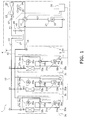
- Fig. 1 is a schematic configuration diagram of an air conditioning apparatus 1 according to an embodiment of the present invention.
- the air conditioning apparatus 1 includes two compressors and two expansion valves within a system of a refrigerant circuit 10 thereof.
- the air conditioning apparatus 1 is an apparatus to be used for conducting cooling and heating operations of the indoor of a building and the like by executing a two-stage compression two-stage expansion refrigeration cycle operation.
- the air conditioning apparatus 1 mainly includes an outdoor unit 2, indoor units 3a to 3c, and a refrigerant communication pipe 4.
- the outdoor unit 2 functions as a heat source unit.
- the indoor units 3a to 3c are connected to the outdoor unit 2, and function as utilization units.
- the refrigerant communication pipe 4 connects the outdoor unit 2 and the indoor units 3a to 3c.
- the refrigerant communication pipe 4 is composed of a liquid refrigerant communication pipe 41 and a gas refrigerant communication pipe 42.
- the refrigerant circuit 10 of the air conditioning apparatus 1 of the present embodiment is formed by the interconnection among the outdoor unit 2, the indoor units 3a to 3c, and the refrigerant communication pipe 4.
- the outdoor unit 2 is disposed outside a building and the like.
- the outdoor unit 2 is connected to the indoor units 3a to 3c through the refrigerant communication pipe 4.
- the outdoor unit 2 forms a part of the refrigerant circuit 10.
- the outdoor unit 2 mainly includes an outdoor side refrigerant circuit 20.
- the outdoor side refrigerant circuit 20 forms a part of the refrigerant circuit 10.
- the outdoor side refrigerant circuit 20 mainly includes an outdoor compressor 21, an outdoor four-way switch valve V1, an outdoor heat exchanger 23 functioning as a heat source side heat exchanger, an outdoor expansion valve V2 functioning as an expansion mechanism, a gas liquid separator 27, a liquid side stop valve V3 and a gas side stop valve V4.
- the outdoor compressor 21 is a compressor capable of changing its operation capacity.
- the outdoor compressor 21 is a positive-displacement compressor to be driven by a motor 22.
- rotation speed of the motor 22 is controlled by an inverter.
- the outdoor compressor 21 functions as a compressor on the higher stage of the two-stage compression two-stage expansion refrigeration cycle in a cooling operation. It also functions as a compressor on the lower stage of the two-stage compression two-stage expansion refrigeration cycle in a heating operation.
- the two-stage compression two-stage expansion refrigeration cycle will be hereinafter explained. Note that only single outdoor compressor 21 is provided in the present embodiment. However, the number of the outdoor compressor 21 is not limited to this. For example, two or more compressors may be parallel-connected in accordance with the number of connected indoor units or the like.
- the outdoor four-way switch valve V1 is a valve provided for causing the outdoor heat exchanger 23 to function as a condenser and an evaporator.
- the outdoor four-way switch valve V1 is connected to the outdoor heat exchanger 23, a suction side of the outdoor compressor 21, a discharge side of the outdoor compressor 21, and the gas refrigerant communication pipe 42.
- the outdoor four-way switch valve V1 is configured to connect the discharge side of the outdoor compressor 21 and the outdoor heat exchanger 23, and is also configured to connect the suction side of the outdoor compressor 21 and the gas refrigerant communication pipe 42 (see a solid-line condition in Fig. 1 ).
- the outdoor four-way switch valve V1 is configured to connect the outdoor heat exchanger 23 and the suction side of the outdoor compressor 21, and is also configured to connect the discharge side of the outdoor compressor 21 and the gas refrigerant communication pipe 42 (see a dashed-line condition in Fig. 1 ).
- the outdoor heat exchanger 23 is a heat exchanger allowed to function as a condenser and an evaporator.
- the outdoor heat exchanger 23 is a cross-fin typed fin-and-tube heat exchanger for conducting heat exchange between the refrigerant and air functioning as a heat source.
- One end of the outdoor heat exchanger 23 is connected to the outdoor four-way switch valve V1 while the other end thereof is connected to the liquid refrigerant communication pipe 41 via the outdoor expansion valve V2.
- the outdoor expansion valve V2 is an electric expansion valve for regulating the pressure, the flow rate and the like of refrigerant flowing through the outdoor side refrigerant circuit 20.
- the outdoor expansion valve V2 is connected to the liquid side of the outdoor heat exchanger 23.
- the outdoor expansion valve V2 is configured to function as a first-stage expansion mechanism of the two-stage compression two-stage expansion refrigeration cycle in a cooling operation.
- the outdoor expansion valve V2 is configured to function as a second-stage expansion mechanism of the two-stage compression two-stage expansion refrigeration cycle in a heating operation.
- the outdoor expansion valve V2 functions as the first-stage expansion mechanism, it decompresses the refrigerant of high pressure Ph to intermediate pressure Pm.
- the outdoor expansion valve V2 functions as the second-stage expansion mechanism, it decompresses the refrigerant of the intermediate pressure Pm to low pressure P1.
- the gas liquid separator 27 is capable of storing liquid refrigerant by separating the gas-liquid two-phase state refrigerant into liquid refrigerant and gas refrigerant.
- the gas-liquid two-phase state refrigerant flows into the gas liquid separator 27 after it is decompressed to the intermediate pressure Pm by the outdoor expansion valve V2 or an indoor expansion valve V7 (see the following description).
- the liquid refrigerant stored in the gas liquid separator 27 is transported to the indoor expansion valve V7 in the cooling operation whereas it is transported to the outdoor expansion valve V2 in the heating operation.
- the gas refrigerant separated from the gas-liquid two-phase state refrigerant by the gas liquid separator 27 is transported to a pipe between the gas side stop valve V4 and the outdoor four-way switch valve V1 through a bypass circuit 28.
- the bypass circuit 28 includes a bypass valve V5 capable of controlling the flow rate of the gas refrigerant.
- the outdoor unit 2 includes an outdoor fan 24.
- the outdoor fan 24 functions as a ventilation fan for sucking outdoor air into the outdoor unit 2 and then discharging the sucked air to the outside after the outdoor heat exchanger 23 conducts heat exchange between the inhaled air and the refrigerant.
- the outdoor fan 24 is capable of changing the flow rate of air to be supplied to the outdoor heat exchanger 23.
- the outdoor fan 24 is a propeller fan to be driven by a motor 25, for instance.
- the motor 25 is composed of a DC fan motor.
- the outdoor unit 2 includes an outdoor side control unit 26.
- the outdoor side control unit 26 is configured to control operations of each of the elements forming the outdoor unit 2.
- the outdoor side control unit 26 includes a microcomputer, a memory, an inverter circuit and the like.
- the microcomputer is provided for controlling the outdoor unit 2.
- the inverter circuit is configured to control the motor 22 and the like.
- the outdoor side control unit 26 is capable of transmitting/receiving a control signal and the like to/from after-mentioned indoor side control units 36a to 36c of the indoor units 3a to 3c through a transmission line 51.
- the outdoor side control unit 26, the indoor side control units 36a to 36c and the transmission line 51 connecting each of the control units form a control section 5 for controlling the entire operation of the air conditioning apparatus 1.
- control section 5 The elements of the control section 5 are connected so as to be capable of receiving detection signals from a variety of sensors (not illustrated in the figure) and so as to be capable of controlling the various devices 21, 24, 31a to 31c, and 34a to 34c, and valves V1, V2, V6a to V6c, and V7a to V7c, respectively, based on the detection signals and the like.
- the indoor units 3a to 3c are installed by being embedded in or hanged down from the ceiling or by being hung on the wall of the inside of a building and the like.
- the indoor units 3a to 3c are connected to the outdoor unit 2 through the refrigerant communication pipe 4.
- the indoor units 3a to 3c form a part of the refrigerant circuit 10.
- the indoor unit 3a and the other indoor units 3b and 3c have the same configurations. Accordingly, only the configuration of the indoor unit 3a will be hereinafter explained. Explanation of the configurations of the indoor units 3b and 3c will be omitted by assigning reference numerals of "Xb" and "Xc" to elements of the indoor units 3b and 3c instead of assigning reference numeral of "Xa" corresponding to each of the elements of the indoor unit 3a.
- the indoor fan 34a of the indoor unit 3a corresponds to the indoor fans 34b and 34c of the indoor units 3b and 3c.
- the indoor unit 3a mainly includes an indoor side refrigerant circuit 30a.
- the indoor side refrigerant circuit 30a forms a part of the refrigerant circuit 10.
- the indoor side refrigerant circuit 30a mainly includes an indoor compressor 31a, an indoor four-way switch valve V6a, an indoor expansion valve V7a functioning as an expansion mechanism, and an indoor heat exchanger 33a functioning as a utilization side heat exchanger.
- the indoor compressor 31a is a compressor capable of changing its operation capacity.
- the indoor compressor 31a is a positive-displacement compressor to be driven by a motor 32a. Rotation speed of the motor 32a is controlled by an inverter.
- the indoor compressor 31 a is configured to function as a compressor on the lower stage of the two-stage compression two-stage expansion refrigeration cycle in the cooling operation. On the other hand, it is configured to function as a compressor on the higher stage of the two-stage compression two-stage expansion refrigeration cycle in the heating operation.
- the indoor compressor 31 a is capable of controlling its operation capacity depending on operation load to be applied in air-conditioning of the indoor space.
- the air conditioning apparatus 1 includes three indoor units 3a to 3c.
- the indoor units 3a to 3c are configured to control operational capacities of the indoor compressors 31a to 31 c provided therein, respectively, depending on operation loads of the indoor units 3a to 3c to be applied in air-conditioning of their corresponding indoor spaces.
- the indoor four-way switch valve V6a is a valve provided for causing the indoor heat exchanger 33a to function as an evaporator and a condenser.
- the indoor four-way switch valve V6a is similar to the outdoor four-way switch valve V1.
- the indoor four-way switch valve V6a is connected to the indoor heat exchanger 33a, a suction side of the indoor compressor 31 a, a discharge side of the indoor compressor 31 a and the gas refrigerant communication pipe 42.
- the indoor four-way switch valve V6a is configured to connect the discharge side of the indoor compressor 31a and the indoor heat exchanger 33a, and is also configured to connect the suction side of the indoor compressor 31 a and the gas refrigerant communication pipe 42 (see the dashed-line condition in Fig. 1 ).
- the indoor four-way switch valve V6a is configured to connect the indoor heat exchanger 33a and the suction side of the indoor compressor 31a, and is also configured to connect the discharge side of the indoor compressor 31a and the gas refrigerant communication pipe 42 (see the solid-line condition in Fig. 1 ).
- the outdoor four-way switch valve V1 and the indoor four-way switch valve V6a are configured to function in conjunction with each other as hereinafter described.
- the indoor four-way switch valve V6a is switched to a condition for causing the indoor heat exchanger 33a to function as an evaporator.
- the indoor four-way switch valve V6a is switched to a condition for causing the indoor heat exchanger 3 3 a to function as a condenser.
- the indoor expansion valve V7a is an electric expansion valve for regulating the pressure, the flow rate and the like of the refrigerant flowing through the indoor side refrigerant circuit 30a.
- the indoor expansion valve V7a is connected to the liquid side of the indoor heat exchanger 33a.
- the indoor expansion valve V7a is similar to the outdoor expansion valve V2.
- the indoor expansion valve V7a is configured to function as a second-stage expansion mechanism of the second-stage compression second-stage expansion refrigeration cycle in the cooling operation. On the other hand, it is configured to function as a first-stage expansion mechanism of the second-stage compression second-stage expansion refrigeration cycle in the heating operation.
- the indoor expansion valve V7a When the indoor expansion valve V7a functions as the first-stage expansion mechanism, it decompresses the refrigerant of the high pressure Ph to the intermediate pressure Pm. On the other hand, when the indoor expansion valve V7a functions as the second-stage expansion mechanism, it decompresses the refrigerant of the intermediate pressure Pm to the low pressure P1. In this regard, the indoor expansion valve V7a is also similar to the outdoor expansion valve V2.
- the indoor heat exchanger 33a is a cross-fin typed fin-and-tube heat exchanger formed by a heat transmission tube and a plurality of fins.
- the indoor heat exchanger 33a is configured to function as an evaporator of the refrigerant for cooling the indoor air in the cooling operation.
- it is configured to function as a condenser of the refrigerant for heating the indoor air in the heating operation.
- the indoor unit 3a includes the indoor fan 34a.
- the indoor fan 34a functions as a ventilation fan for sucking indoor air into the indoor unit 3a and subsequently causing the sucked air to exchange heat with the refrigerant in the indoor heat exchanger 33a and thereafter supplying it as the supply air.
- the indoor fan 34a is capable of changing the flow rate of air to be supplied to the indoor heat exchanger 33a.
- the indoor fan 34a may be a centrifugal fan, a multi-blade fan and the like to be driven by a motor 35a.
- the motor 35a is composed of a DC fan motor.
- the indoor unit 3a is provided with the indoor side control unit 36a for controlling operations of each of the elements forming the indoor unit 3a.
- the indoor side control unit 36a includes a microcomputer, a memory and the like provided for controlling the indoor unit 3a.
- the indoor side control unit 36a is capable of transmitting/receiving a control signal and the like to/from a remote controller (not illustrated in the figure) for controlling the indoor unit 3a independently from the other indoor units.
- the indoor side control unit 36a is capable of transmitting/receiving a control signal and the like to/from the outdoor unit 2 through the transmission line 51.
- the refrigerant communication pipe 4 is attached to the air conditioning apparatus 1 in the installation site.
- Any suitable refrigerant communication pipes 4 of a variety of lengths and diameters may be used depending on installation conditions (e.g., an installation site and a combination of the outdoor unit 2 and the indoor units 3a to 3c).
- the air conditioning apparatus 1 of the present embodiment is configured to be operated in two operation modes depending on loads of the indoor units 3a to 3c applied in cooling and heating of the indoor space.
- One of the operation modes is a cooling operation for causing the indoor units 3a to 3c to cool the indoor space whereas the other of the operation modes is a heating operation for causing the indoor units 3a to 3c to heat the indoor space.
- the outdoor four-way switch valve V1 in the outdoor side refrigerant circuit 20 of the outdoor unit 2 is switched to the solid-line condition in Fig. 1
- the indoor four-way switch valves V6a to V6c in the indoor side refrigerant circuits 30a to 30c of the indoor units 3a to 3c are switched to the solid-line condition in Fig. 1 .
- the outdoor heat exchanger 23 is configured to function as a condenser
- the indoor heat exchangers 33a to 33c are configured to function as evaporators.
- the gas refrigerant of the low pressure Pl is inhaled into the indoor compressors 31 a to 31c, and is compressed to the intermediate pressure Pm.
- the compressed gas refrigerant of the intermediate pressure Pm is transported to the gas refrigerant communication pipe 42 via the indoor four-way switch valves V6a to V6c. After the gas refrigerant of the intermediate pressure Pm is transported to the gas refrigerant communication pipe 42, it flows into the outdoor unit 2 through the gas side stop valve V4.
- the gas refrigerant flows into the outdoor unit 2, it merges with the gas refrigerant (i.e., injection gas) flowing from the gas liquid separator 27 via the bypass circuit 28.
- the injection gas is separated from the gas-liquid two-phase state refrigerant by the gas liquid separator 27.
- the merged gas refrigerant flows into the outdoor compressor 21 via the outdoor four-way switch valve V1.
- the outdoor heat exchanger 23 functions as a condenser, and cools the refrigerant by releasing heat of the refrigerant into the outdoor air to be supplied by the outdoor fan 24.
- the outdoor expansion valve V2 decompresses the refrigerant of the high pressure Ph to the intermediate pressure Pm.
- the refrigerant decompressed to the intermediate pressure Pm is in a gas-liquid two-phase state, and flows into the gas liquid separator 27.
- the gas liquid separator 27 separates the refrigerant into the liquid refrigerant and the gas refrigerant.
- the gas liquid separator 27 discharges the liquid refrigerant of the intermediate pressure Pm to a pipe in the liquid stop valve V3 side, and discharges the gas refrigerant of the intermediate pressure Pm toward the suction side of the outdoor compressor 21 through the bypass circuit 28.
- the liquid refrigerant of the intermediate pressure Pm is transported to the indoor units 3a to 3c via the liquid side stop valve V3 and the liquid refrigerant communication pipe 41. After the liquid refrigerant of the intermediate pressure Pm is transported to the indoor units 3a to 3c, it is decompressed to approximately the intake pressure of the indoor compressors 31a to 31c by the indoor expansion valves V7a to V7c. Accordingly, the liquid refrigerant changes into gas-liquid two-phase state refrigerant of the low pressure P1, and is transported to the indoor heat exchangers 33a to 33c. Subsequently, the indoor heat exchangers 33a to 33c conduct heat exchange between the refrigerant and the indoor air.
- the refrigerant evaporates and changes into gas refrigerant of the low pressure Pl.
- the gas refrigerant of the low pressure Pl is again inhaled into the indoor compressors 31a to 31c via the indoor four-way switch valves V6a to V6c.
- the outdoor four-way switch valve V1 in the outdoor side refrigerant circuit 20 of the outdoor unit 2 is switched to the dashed-line condition in Fig. 1
- the indoor four-way switch valves V6a to V6c in the indoor side refrigerant circuits 30a to 30c of the indoor units 3a to 3c are switched to the dashed-line condition in Fig. 1 .
- the outdoor heat exchanger 23 is configured to function as an evaporator whereas the indoor heat exchangers 33a to 33c are configured to function as condensers.
- gas refrigerant of the low pressure Pl is inhaled into the outdoor compressor 21 and is compressed therein.
- the gas refrigerant of the low pressure P1 accordingly changes into gas refrigerant of the intermediate pressure Pm.
- the gas refrigerant of the intermediate pressure Pm flows through the outdoor four-way switch valve V1, and merges with the gas refrigerant (i.e., injection gas) flowing from the gas liquid separator 27 via the bypass circuit 28.
- the injection gas is separated from the gas-liquid two-phase state refrigerant by the gas liquid separator 27.
- the merged gas refrigerant of the intermediate pressure Pm is transported to the gas refrigerant communication pipe 42 via the gas side stop valve V4.
- the gas refrigerant of the intermediate pressure Pm is transported to the gas refrigerant communication pipe 42, it is further transported to the indoor units 3a to 3c.
- the gas refrigerant of the intermediate pressure Pm transported to the indoor units 3a to 3c is compressed by the indoor compressors 31 a to 31 c to a supercritical state of high temperature and high pressure.
- the refrigerant of a supercritical state is transported to the indoor heat exchangers 33a to 33c via the indoor four-way switch valves V6a to V6c.
- the indoor heat exchangers 33a to 33c conduct heat exchange between the refrigerant and the indoor air. Accordingly, the refrigerant is condensed and changes into liquid refrigerant of the high pressure Ph.
- the refrigerant After the refrigerant passes through the indoor expansion valves V7a to V7c, it is transported to the outdoor unit 2 via the liquid refrigerant communication pipe 41.
- the refrigerant of the intermediate pressure Pm flows into the outdoor unit 2 via the liquid side stop valve V3.
- the refrigerant of the intermediate pressure Pm is in a gas-liquid two-phase state, and flows into the gas liquid separator 27.
- the gas liquid separator 27 separates the refrigerant into the liquid refrigerant and the gas refrigerant.
- the gas liquid separator 27 discharges the liquid refrigerant of the intermediate pressure Pm to a pipe in the outdoor expansion valve V2 side whereas it discharges the gas refrigerant of the intermediate pressure Pm toward the suction side of the outdoor compressor 21 via the bypass circuit 28.
- the liquid refrigerant of the intermediate pressure Pm is further decompressed to the low pressure Pl through the outdoor expansion valve V2.
- the liquid refrigerant of the low pressure Pl thereafter flows into the outdoor heat exchanger 23.
- the refrigerant of the low pressure P1 flowing into the outdoor heat exchanger 23 is in a gas-liquid two-phase state, and evaporates in the course of heat exchange with the outdoor air to be supplied by the outdoor fan 24. Accordingly, the refrigerant changes into gas refrigerant of the low pressure P1.
- the gas refrigerant is again inhaled into the outdoor compressor 21 via the outdoor four-way switch valve V1.
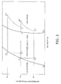
- Fig. 2 illustrates the refrigeration cycle under the supercritical condition with P-H chart (Mollier diagram).
- the CO 2 refrigerant i.e., the supercritical refrigerant
- the present invention adopts the two-stage compression two-stage expansion refrigeration cycle configured to compress the refrigerant in two stages with two compressors provided in one system in the refrigerant circuit 10, and is configured to expand the refrigerant in two stages with two expansion mechanisms provided in one system in the refrigerant circuit 10.
- the two-stage compression two-stage expansion cycle will be explained with reference to Figs. 1 and 2 . The following is an explanation of the two-stage compression two-stage expansion cycle in the aforementioned cooling operation.
- the refrigerant circuit 10 is mainly composed of the indoor compressors 31a to 31c, the outdoor compressor 21, the outdoor heat exchanger 23, the outdoor expansion valve V2, the indoor expansion valves V7a to V7c and the indoor heat exchangers 33a to 33c.
- Points A1, B1, C1, D1, E1, F1, G1, H1 and I1 in Fig. 2 illustrate states of the refrigerant at the corresponding points in Fig. 1 , respectively.
- the indoor compressors 31 a to 31c compress the refrigerant and the compressed refrigerant changes into high-temperature refrigerant of the intermediate pressure Pm (A1 ⁇ B2).
- the high temperature refrigerant compressed to the intermediate pressure Pm passes through the gas refrigerant communication pipe 42 without changing the intermediate pressure Pm, and merges with the gas refrigerant (i.e., injection gas) of the intermediate pressure Pm separated from the gas-liquid two-phase state refrigerant by the gas liquid separator 27. Accordingly, the high temperature refrigerant of the intermediate pressure Pm is cooled (B1 + I1 ⁇ C1).
- the outdoor compressor 21 compresses the gas refrigerant of the intermediate pressure Pm cooled by merging with the injection gas.
- the gas refrigerant of the intermediate pressure Pm changes into high-temperature refrigerant of the high pressure Ph (C1 ⁇ D1).
- the gas refrigerant, CO 2 enters a supercritical state.
- supercritical state herein means a state of material under temperature and pressure equal to or greater than the critical point K.
- the supercritical state has both gas diffusivity and liquid solubility.
- the supercritical state of the refrigerant is shown in the area positioned rightward of a critical temperature isothermal curve Tk (not shown) at the critical pressure Pk (not shown) or greater.
- the term "gas phase” is a state of the refrigerant shown by the area positioned rightward of a saturated vapor curve Sv at the critical pressure Pk or less.
- the term “liquid phase” is a state of the refrigerant shown by the area positioned leftward of both a saturated liquid curve S1 and the critical temperature isothermal curve Tk.
- the refrigerant operates with sensible heat change (i.e., temperature change) in the interior of the outdoor heat exchanger 23.
- the refrigerant is expanded in conjunction with opening of the outdoor expansion valve V2. Accordingly, the refrigerant is decompressed from the high pressure Ph to the intermediate pressure Pm (E1 ⁇ F1).
- the refrigerant decompressed by the outdoor expansion valve V2 is in a gas-liquid two-phase state, and flows into the gas liquid separator 27.
- the gas liquid separator 27 separates the refrigerant into the liquid refrigerant and the gas refrigerant.
- the gas liquid separator 27 flows the liquid refrigerant of the intermediate pressure Pm into a pipe in the liquid stop valve V3 side is attached (F1 ⁇ G1) whereas it flows the gas refrigerant of the intermediate pressure Pm toward the suction side of the outdoor compressor 21 through the bypass circuit 28 (F1 ⁇ I1).
- the liquid refrigerant of the intermediate pressure Pm passes through the liquid refrigerant communication pipe 41, and is further expanded by the indoor expansion valves V7a to V7c. Accordingly, the refrigerant changes into liquid refrigerant of the low pressure Pl (G1 ⁇ H1).
- the liquid refrigerant of the low pressure Pl absorbs heat and evaporates in the indoor heat exchangers 33a to 33c, and returns to the indoor compressors 31a to 31c (H1 ⁇ A1).
- the air conditioning apparatus of the present invention is capable of reducing cost necessary for update/renewal construction of an already-installed air conditioning apparatus because an already-disposed refrigerant communication pipe is allowed to be used without any changes. Additionally, the air conditioning apparatus is useful for a variety of apparatuses including an air conditioning apparatus required to have high design pressure (e.g., an air conditioning apparatus configured to operate with the CO 2 refrigerant and the like).
Landscapes
- Engineering & Computer Science (AREA)
- Mechanical Engineering (AREA)
- General Engineering & Computer Science (AREA)
- Physics & Mathematics (AREA)
- Thermal Sciences (AREA)
- Chemical & Material Sciences (AREA)
- Combustion & Propulsion (AREA)
- Air Conditioning Control Device (AREA)
- Compression-Type Refrigeration Machines With Reversible Cycles (AREA)
Abstract
Description
- The present invention relates to a multi-type air conditioning apparatus in which a plurality of indoor units are connected to an outdoor unit.
- The so-called multi-type air conditioning apparatus has conventionally been produced. In the multi-type air conditioning apparatus, a plurality of indoor units are connected to single outdoor unit. For example, this is described in
Patent Document 1. In the multi-type air conditioning apparatus, it is possible to arbitrarily combine a plurality of indoor units having different operation capacities depending on usage types of structures (e.g., buildings). Accordingly, the multi-type air conditioning apparatus is capable of individually conducting air conditioning on a floor-to-floor basis and a space-to-space basis. In other words, it is possible to arbitrarily combine a plurality of indoor units depending on operation loads to be applied in cooling and heating of the respective indoor spaces. Consequently, the multi-type air conditioning apparatus is capable of conducting air conditioning without consuming unnecessary energy. - Japanese Laid-open Patent Application No.
JP-H11-118275 - However, the aforementioned multi-type air conditioning apparatus is not capable of accurately changing evaporation temperature or condensation temperature in each indoor unit. Because of this, for instance, when the multi-type air conditioning apparatus simultaneously includes a type of indoor unit configured to be operated with operation capacity approximately the same as the maximum capacity and a type of indoor unit configured to be operated with operation capacity less than the maximum capacity, the latter indoor unit is required to set degree of superheating of an outlet of an evaporator to be large in a cooling operation. Furthermore, the latter indoor unit is required to set degree of subcooling of a condenser to be large in a heating operation. Accordingly, operational efficiency of the multi-type air conditioning apparatus may be worse.
- An object of the present invention is to provide a multi-type air conditioning apparatus capable of controlling necessary operation capacities of a plurality of indoor units in accordance with their operation loads, respectively.
- An air conditioning apparatus according to a first aspect of the present invention is an air conditioning apparatus configured to conduct air conditioning by changing a state of refrigerant. The air conditioning apparatus includes a heat source unit, a first utilization unit, a second utilization unit, a refrigerant communication pipe and a control section. The heat source unit includes a heat source side compressor, a heat source side heat exchanger and a heat source side expansion mechanism. The heat source side compressor is configured to compress the refrigerant. The heat source side heat exchanger is configured to conduct heat exchange of the refrigerant. The heat source side expansion mechanism is configured to decompress the refrigerant. The first utilization unit includes a first utilization side compressor, a first utilization side heat exchanger and a first utilization side expansion mechanism. The first utilization side compressor is configured to compress the refrigerant. The first utilization side heat exchanger is configured to conducting heat exchange of the refrigerant. The first utilization side expansion mechanism is configured to decompress the refrigerant. The second utilization unit includes a second utilization side compressor, a second utilization side heat exchanger, and a second utilization side expansion mechanism. The second utilization side compressor is configured to compress the refrigerant. The second utilization side heat exchanger is configured to conduct heat exchange of the refrigerant. The second utilization side expansion mechanism is configured to decompress the refrigerant. The refrigerant communication pipe connects the heat source unit and both the first and second utilization units. The control section is configured to control the first utilization side compressor and the first utilization side expansion mechanism in accordance with operation load of the first utilization unit and control the second utilization side compressor and the second utilization side expansion mechanism in accordance with operation load of the second utilization unit.
- According to the first aspect of the present invention, a plurality of utilization units (i.e., the first and second utilization units) are provided, and not only the heat source unit but also each of the first and second utilization units is provided with the first utilization side compressor and the second utilization side compressor. Furthermore, the control section is configured to control the first utilization side compressor and the first utilization side expansion mechanism in accordance with operation load of the first utilization unit and control the second utilization side compressor and the second utilization side expansion mechanism in accordance with operation load of the second utilization unit.
- With the structure, for instance, each of the utilization units is allowed to independently control evaporation temperature of the refrigerant in a cooling operation and high pressure of refrigerant in a heating operation. Accordingly, the air conditioning apparatus is capable of accurately controlling operation capacity of each utilization unit depending on its operation load. Consequently, the air conditioning apparatus is capable of enhancing its operation efficiency and saving energy.
- An air conditioning apparatus according to a second aspect of the present invention is the air conditioning apparatus according to the first aspect of the present invention, wherein the first utilization side compressor and the second utilization side compressor are allowed to be controlled by an inverter.
- According to the second aspect of the present invention, the first utilization side compressor and the second utilization side compressor are capacity variable compressors, and are allowed to be controlled by an inverter. With the structure, the air conditioning apparatus is capable of controlling capacity of the first utilization side compressor for allowing the first utilization side compressor to operate with operation capacity depending on operation load of the first utilization unit. Furthermore, the air conditioning apparatus is capable of controlling capacity of the second utilization side compressor for allowing the second utilization side compressor to operate with operation capacity depending on operation load of the second utilization unit.
- An air conditioning apparatus according to a third aspect of the present invention is the air conditioning apparatus according to the first aspect or the second aspect of the present invention, wherein the heat source unit further includes an intermediate cooler.
- According to the third aspect of the present invention, the heat source unit is provided with the intermediate cooler for cooling liquid refrigerant of intermediate pressure and gas refrigerant of intermediate pressure. Gas-liquid two-phase state refrigerant, expanded to the intermediate pressure by the higher-stage expansion mechanism, and gas refrigerant, compressed to the intermediate pressure by the lower-stage compressor, pass through the intermediate cooler. In this case, part of the liquid refrigerant is evaporated, and accordingly a refrigeration effect is provided for the refrigerant in the intermediate cooler.
- With the structure, it is possible to cool the intermediate-pressure gas refrigerant compressed by the lower-stage compressor to exactly or approximately the saturated state. Additionally, it is similarly possible to cool the liquid refrigerant to the subcooling zone by means of the refrigeration effect. Therefore, it is possible to enhance the refrigeration effect. Furthermore, it is possible to reduce discharge temperature of the higher-stage compressor. Accordingly, it is possible to prevent deterioration of lubricant oil of the higher-stage compressor.
- An air conditioning apparatus according to a fourth aspect of the present invention is the air conditioning apparatus according to any of the first to third aspects of the present invention, wherein the heat source unit further includes a heat source side switch mechanism. The heat source side switch mechanism is capable of switching between a first condition and a second condition. The first condition is a condition for causing the refrigerant compressed to intermediate pressure by the first utilization side compressor or the second utilization side compressor to flow into the heat source side compressor, and for causing the refrigerant compressed to high pressure by the heat source side compressor to flow into the heat source side heat exchanger. The second condition is a condition for causing the low-pressure refrigerant evaporated by the heat source side heat exchanger to flow into the heat source side compressor, and for causing the refrigerant compressed to the intermediate pressure by the heat source side compressor to flow into the first utilization side compressor or the second utilization side compressor. The first utilization unit further includes a first utilization side switch mechanism. The first utilization side switch mechanism is capable of switching between a third condition and a fourth condition. The third condition is a condition for causing the low-pressure refrigerant evaporated by the first utilization side heat exchanger to flow into the first utilization side compressor, and for causing the refrigerant compressed to the intermediate pressure by the first utilization side compressor to flow into the heat source side compressor. The fourth condition is a condition for causing the refrigerant compressed to the intermediate pressure by the heat source side compressor to flow into the first utilization side compressor, and for causing the refrigerant compressed to the high pressure by the first utilization side compressor to flow into the first utilization side heat exchanger. The second utilization unit further includes a second utilization side switch mechanism. The second utilization side switch mechanism is capable of switching between a fifth condition and a sixth condition. The fifth condition is a condition for causing the low-pressure refrigerant evaporated by the second utilization side heat exchanger to flow into the second utilization side compressor, and for causing the refrigerant compressed to the intermediate pressure by the second utilization side compressor to flow into the heat source side compressor. The sixth condition is a condition for causing the refrigerant compressed to the intermediate pressure by the heat source side compressor to flow into the second utilization side compressor, and for causing the refrigerant compressed to the high pressure by the second utilization side compressor to flow into the first utilization side heat exchanger. The control section is configured to conduct first control and second control. The first control is control for setting the heat source side switch mechanism, the first utilization side switch mechanism and the second utilization side switch mechanism to be in the first condition, the third condition and the fifth condition, respectively. The second control is control for setting the heat source side switch mechanism, the first utilization side switch mechanism and the second utilization side switch mechanism to be in the second condition, the fourth condition and the sixth condition, respectively.
- According to the fourth aspect of the present invention, each of the heat source unit, the first utilization unit and the second utilization unit is provided with a switch mechanism (e.g., four-way switch valve) for switching operational conditions (e.g., a heating operation and a cooling operation) back and forth, for instance.
- With the structure, it is possible to switch to use the first utilization side heat exchanger and the second utilization side heat exchanger as gas coolers and use the heat source side heat exchanger as an evaporator. Contrary to this, it is also possible to switch to use the first utilization side heat exchanger and the second utilization side heat exchanger as evaporators and use the heat source side heat exchanger as a gas cooler. Accordingly, it is possible to switch operational conditions of the utilization units between the cooling operation and the heating operation. Thus, it is possible to switch the operational conditions depending on temperature. Consequently, the air conditioning apparatus is capable of providing comfortable air-conditioned space.
- According to the air conditioning apparatus of the first aspect of the present invention, each of the utilization units is allowed to independently control evaporation temperature of refrigerant in the cooling operation and high pressure of refrigerant in the heating operation. Accordingly, the air conditioning apparatus is capable of accurately controlling capacity of each utilization unit in accordance with its operation load, for instance. Consequently, the air conditioning apparatus is capable of enhancing its operational efficiency and saving energy.
- According to the air conditioning apparatus of the second aspect of the present invention, the first utilization side compressor and the second utilization side compressor are capacity variable compressors, and are allowed to be controlled by an inverter. Accordingly, the air conditioning apparatus is capable of controlling capacity of the first utilization side compressor for allowing the first utilization side compressor to operate with operation capacity depending on operation load of the first utilization unit. Furthermore, the air conditioning apparatus is capable of controlling capacity of the second utilization side compressor for allowing the second utilization side compressor to operate with operation capacity depending on operation load of the second utilization unit.
- According to the air conditioning apparatus of the third aspect of the present invention, it is possible to cool the intermediate-pressure gas refrigerant compressed by the lower-stage compressor to exactly or approximately the saturated state. Additionally, it is similarly possible to cool the liquid refrigerant to the subcooling zone by means of the refrigeration effect. Consequently, the air conditioning apparatus is capable of enhancing the refrigeration effect. Furthermore, it is capable of reducing discharge temperature of the higher-stage compressor. Accordingly, the air conditioning apparatus is capable of preventing deterioration of lubricant oil of the higher-stage compressor.
- According to the air conditioning apparatus of the fourth aspect of the present invention, it is possible to switch usage of the first utilization side heat exchanger, the second utilization side heat exchanger and the heat source side heat exchanger. Specifically, it is possible to use the first utilization side heat exchanger and the second utilization side heat exchanger as gas coolers and use the heat source side heat exchanger as an evaporator. Contrary to this, it is also possible to use the first utilization side heat exchanger and the second utilization side heat exchanger as evaporators and use the heat source side heat exchanger as a gas cooler. Accordingly, it is possible to switch operational conditions of the utilization units between the cooling operation and the heating operation. In other words, the air conditioning apparatus is capable of switching operational conditions depending on temperature. Therefore, it is capable of providing a comfortable air-conditioned space.
-
-
Fig. 1 is a refrigerant circuit diagram of an air conditioning apparatus according to an embodiment of the present invention. -
Fig. 2 is a P-H chart for illustrating a two-stage compression two-stage expansion refrigeration cycle using carbon dioxide (CO2) refrigerant in the air conditioning apparatus of the present invention. -
Fig. 3 is a refrigerant circuit diagram of an air conditioning apparatus according to Modification (1). -
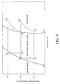
Fig. 4 is a P-H chart for illustrating a two-stage compression two-stage expansion refrigeration cycle using the CO2 refrigerant in the air conditioning apparatus according to Modification (1). -
Fig. 5 is a refrigerant circuit diagram of an air conditioning apparatus according to Modification (2). -
- 1, 1a
- air conditioning apparatus
- 2, 2a
- outdoor unit (heat source unit)
- 3a-3c
- indoor unit (first utilization unit, second utilization unit)
- 4
- refrigerant communication pipe
- 5
- control section
- 8a-8c
- indoor unit (first utilization unit, second utilization unit)
- 21
- outdoor compressor (heat source side compressor)
- 27a
- intermediate cooler
- 31a-31c
- indoor compressor (first utilization side compressor, second utilization side compressor)
- 71a-71c
- indoor compressor (first utilization side compressor, second utilization side compressor)
- V1
- outdoor four-way switch valve (heat source side switch mechanism)
- V2
- outdoor expansion valve (heat source side expansion mechanism)
- V6a-V6c
- second indoor four-way switch valve (first utilization side switch mechanism, utilization side switch mechanism)
- V7a-V7c
- indoor expansion valve (first utilization side expansion mechanism, second utilization side expansion mechanism)
- V8a-V8c
- indoor expansion valve (first utilization side expansion mechanism, second utilization side expansion mechanism)
- V9a-V9c
- second indoor four-way switch valve (first utilization side switch mechanism, utilization side switch mechanism)
- An air conditioning apparatus of an embodiment of the present invention will be hereinafter explained with reference to accompanying drawings.
-
Fig. 1 is a schematic configuration diagram of anair conditioning apparatus 1 according to an embodiment of the present invention. Theair conditioning apparatus 1 includes two compressors and two expansion valves within a system of arefrigerant circuit 10 thereof. Theair conditioning apparatus 1 is an apparatus to be used for conducting cooling and heating operations of the indoor of a building and the like by executing a two-stage compression two-stage expansion refrigeration cycle operation. Theair conditioning apparatus 1 mainly includes anoutdoor unit 2,indoor units 3a to 3c, and arefrigerant communication pipe 4. Theoutdoor unit 2 functions as a heat source unit. Theindoor units 3a to 3c are connected to theoutdoor unit 2, and function as utilization units. Therefrigerant communication pipe 4 connects theoutdoor unit 2 and theindoor units 3a to 3c. Therefrigerant communication pipe 4 is composed of a liquidrefrigerant communication pipe 41 and a gasrefrigerant communication pipe 42. In other words, therefrigerant circuit 10 of theair conditioning apparatus 1 of the present embodiment is formed by the interconnection among theoutdoor unit 2, theindoor units 3a to 3c, and therefrigerant communication pipe 4. - The
outdoor unit 2 is disposed outside a building and the like. Theoutdoor unit 2 is connected to theindoor units 3a to 3c through therefrigerant communication pipe 4. Theoutdoor unit 2 forms a part of therefrigerant circuit 10. - Next, a configuration of the
outdoor unit 2 will be explained. Theoutdoor unit 2 mainly includes an outdoor siderefrigerant circuit 20. The outdoor siderefrigerant circuit 20 forms a part of therefrigerant circuit 10. The outdoor siderefrigerant circuit 20 mainly includes anoutdoor compressor 21, an outdoor four-way switch valve V1, anoutdoor heat exchanger 23 functioning as a heat source side heat exchanger, an outdoor expansion valve V2 functioning as an expansion mechanism, agas liquid separator 27, a liquid side stop valve V3 and a gas side stop valve V4. - The
outdoor compressor 21 is a compressor capable of changing its operation capacity. In the present embodiment, theoutdoor compressor 21 is a positive-displacement compressor to be driven by amotor 22. Here, rotation speed of themotor 22 is controlled by an inverter. Theoutdoor compressor 21 functions as a compressor on the higher stage of the two-stage compression two-stage expansion refrigeration cycle in a cooling operation. It also functions as a compressor on the lower stage of the two-stage compression two-stage expansion refrigeration cycle in a heating operation. The two-stage compression two-stage expansion refrigeration cycle will be hereinafter explained. Note that only singleoutdoor compressor 21 is provided in the present embodiment. However, the number of theoutdoor compressor 21 is not limited to this. For example, two or more compressors may be parallel-connected in accordance with the number of connected indoor units or the like. - The outdoor four-way switch valve V1 is a valve provided for causing the
outdoor heat exchanger 23 to function as a condenser and an evaporator. The outdoor four-way switch valve V1 is connected to theoutdoor heat exchanger 23, a suction side of theoutdoor compressor 21, a discharge side of theoutdoor compressor 21, and the gasrefrigerant communication pipe 42. When theoutdoor heat exchanger 23 is caused to function as a condenser, the outdoor four-way switch valve V1 is configured to connect the discharge side of theoutdoor compressor 21 and theoutdoor heat exchanger 23, and is also configured to connect the suction side of theoutdoor compressor 21 and the gas refrigerant communication pipe 42 (see a solid-line condition inFig. 1 ). On the other hand, when theoutdoor heat exchanger 23 is caused to function as an evaporator, the outdoor four-way switch valve V1 is configured to connect theoutdoor heat exchanger 23 and the suction side of theoutdoor compressor 21, and is also configured to connect the discharge side of theoutdoor compressor 21 and the gas refrigerant communication pipe 42 (see a dashed-line condition inFig. 1 ). - The
outdoor heat exchanger 23 is a heat exchanger allowed to function as a condenser and an evaporator. In the present embodiment, theoutdoor heat exchanger 23 is a cross-fin typed fin-and-tube heat exchanger for conducting heat exchange between the refrigerant and air functioning as a heat source. One end of theoutdoor heat exchanger 23 is connected to the outdoor four-way switch valve V1 while the other end thereof is connected to the liquidrefrigerant communication pipe 41 via the outdoor expansion valve V2. - The outdoor expansion valve V2 is an electric expansion valve for regulating the pressure, the flow rate and the like of refrigerant flowing through the outdoor side
refrigerant circuit 20. The outdoor expansion valve V2 is connected to the liquid side of theoutdoor heat exchanger 23. The outdoor expansion valve V2 is configured to function as a first-stage expansion mechanism of the two-stage compression two-stage expansion refrigeration cycle in a cooling operation. On the other hand, the outdoor expansion valve V2 is configured to function as a second-stage expansion mechanism of the two-stage compression two-stage expansion refrigeration cycle in a heating operation. When the outdoor expansion valve V2 functions as the first-stage expansion mechanism, it decompresses the refrigerant of high pressure Ph to intermediate pressure Pm. On the other hand, when the outdoor expansion valve V2 functions as the second-stage expansion mechanism, it decompresses the refrigerant of the intermediate pressure Pm to low pressure P1. - The
gas liquid separator 27 is capable of storing liquid refrigerant by separating the gas-liquid two-phase state refrigerant into liquid refrigerant and gas refrigerant. Here, the gas-liquid two-phase state refrigerant flows into thegas liquid separator 27 after it is decompressed to the intermediate pressure Pm by the outdoor expansion valve V2 or an indoor expansion valve V7 (see the following description). The liquid refrigerant stored in thegas liquid separator 27 is transported to the indoor expansion valve V7 in the cooling operation whereas it is transported to the outdoor expansion valve V2 in the heating operation. Furthermore, the gas refrigerant separated from the gas-liquid two-phase state refrigerant by thegas liquid separator 27 is transported to a pipe between the gas side stop valve V4 and the outdoor four-way switch valve V1 through abypass circuit 28. Thebypass circuit 28 includes a bypass valve V5 capable of controlling the flow rate of the gas refrigerant. - Furthermore, the
outdoor unit 2 includes anoutdoor fan 24. Theoutdoor fan 24 functions as a ventilation fan for sucking outdoor air into theoutdoor unit 2 and then discharging the sucked air to the outside after theoutdoor heat exchanger 23 conducts heat exchange between the inhaled air and the refrigerant. Theoutdoor fan 24 is capable of changing the flow rate of air to be supplied to theoutdoor heat exchanger 23. In the present embodiment, theoutdoor fan 24 is a propeller fan to be driven by amotor 25, for instance. Themotor 25 is composed of a DC fan motor. - Additionally, the
outdoor unit 2 includes an outdoorside control unit 26. The outdoorside control unit 26 is configured to control operations of each of the elements forming theoutdoor unit 2. The outdoorside control unit 26 includes a microcomputer, a memory, an inverter circuit and the like. The microcomputer is provided for controlling theoutdoor unit 2. The inverter circuit is configured to control themotor 22 and the like. The outdoorside control unit 26 is capable of transmitting/receiving a control signal and the like to/from after-mentioned indoorside control units 36a to 36c of theindoor units 3a to 3c through atransmission line 51. In other words, the outdoorside control unit 26, the indoorside control units 36a to 36c and thetransmission line 51 connecting each of the control units form acontrol section 5 for controlling the entire operation of theair conditioning apparatus 1. - The elements of the
control section 5 are connected so as to be capable of receiving detection signals from a variety of sensors (not illustrated in the figure) and so as to be capable of controlling thevarious devices - The
indoor units 3a to 3c are installed by being embedded in or hanged down from the ceiling or by being hung on the wall of the inside of a building and the like. Theindoor units 3a to 3c are connected to theoutdoor unit 2 through therefrigerant communication pipe 4. Theindoor units 3a to 3c form a part of therefrigerant circuit 10. - Next, a configuration of the
indoor units 3a to 3c will be explained. Note that theindoor unit 3a and the otherindoor units indoor unit 3a will be hereinafter explained. Explanation of the configurations of theindoor units indoor units indoor unit 3a. For example, theindoor fan 34a of theindoor unit 3a corresponds to theindoor fans indoor units - The
indoor unit 3a mainly includes an indoor siderefrigerant circuit 30a. The indoor siderefrigerant circuit 30a forms a part of therefrigerant circuit 10. The indoor siderefrigerant circuit 30a mainly includes anindoor compressor 31a, an indoor four-way switch valve V6a, an indoor expansion valve V7a functioning as an expansion mechanism, and anindoor heat exchanger 33a functioning as a utilization side heat exchanger. - The
indoor compressor 31a is a compressor capable of changing its operation capacity. In the present embodiment, theindoor compressor 31a is a positive-displacement compressor to be driven by amotor 32a. Rotation speed of themotor 32a is controlled by an inverter. Theindoor compressor 31 a is configured to function as a compressor on the lower stage of the two-stage compression two-stage expansion refrigeration cycle in the cooling operation. On the other hand, it is configured to function as a compressor on the higher stage of the two-stage compression two-stage expansion refrigeration cycle in the heating operation. Theindoor compressor 31 a is capable of controlling its operation capacity depending on operation load to be applied in air-conditioning of the indoor space. In the present embodiment, theair conditioning apparatus 1 includes threeindoor units 3a to 3c. Theindoor units 3a to 3c are configured to control operational capacities of theindoor compressors 31a to 31 c provided therein, respectively, depending on operation loads of theindoor units 3a to 3c to be applied in air-conditioning of their corresponding indoor spaces. - The indoor four-way switch valve V6a is a valve provided for causing the
indoor heat exchanger 33a to function as an evaporator and a condenser. In this regard, the indoor four-way switch valve V6a is similar to the outdoor four-way switch valve V1. The indoor four-way switch valve V6a is connected to theindoor heat exchanger 33a, a suction side of theindoor compressor 31 a, a discharge side of theindoor compressor 31 a and the gasrefrigerant communication pipe 42. When theindoor heat exchanger 33a is caused to function as a condenser, the indoor four-way switch valve V6a is configured to connect the discharge side of theindoor compressor 31a and theindoor heat exchanger 33a, and is also configured to connect the suction side of theindoor compressor 31 a and the gas refrigerant communication pipe 42 (see the dashed-line condition inFig. 1 ). On the other hand, when theindoor heat exchanger 33a is caused to function as an evaporator, the indoor four-way switch valve V6a is configured to connect theindoor heat exchanger 33a and the suction side of theindoor compressor 31a, and is also configured to connect the discharge side of theindoor compressor 31a and the gas refrigerant communication pipe 42 (see the solid-line condition inFig. 1 ). Note that the outdoor four-way switch valve V1 and the indoor four-way switch valve V6a are configured to function in conjunction with each other as hereinafter described. When the outdoor four-way switch valve V1 is switched to a condition for causing theoutdoor heat exchanger 23 to function as a condenser, the indoor four-way switch valve V6a is switched to a condition for causing theindoor heat exchanger 33a to function as an evaporator. On the other hand, when the outdoor four-way switch valve V1 is switched to a condition for causing theoutdoor heat exchanger 23 to function as an evaporator, the indoor four-way switch valve V6a is switched to a condition for causing the indoor heat exchanger 3 3 a to function as a condenser. - The indoor expansion valve V7a is an electric expansion valve for regulating the pressure, the flow rate and the like of the refrigerant flowing through the indoor side
refrigerant circuit 30a. The indoor expansion valve V7a is connected to the liquid side of theindoor heat exchanger 33a. In this regard, the indoor expansion valve V7a is similar to the outdoor expansion valve V2. The indoor expansion valve V7a is configured to function as a second-stage expansion mechanism of the second-stage compression second-stage expansion refrigeration cycle in the cooling operation. On the other hand, it is configured to function as a first-stage expansion mechanism of the second-stage compression second-stage expansion refrigeration cycle in the heating operation. When the indoor expansion valve V7a functions as the first-stage expansion mechanism, it decompresses the refrigerant of the high pressure Ph to the intermediate pressure Pm. On the other hand, when the indoor expansion valve V7a functions as the second-stage expansion mechanism, it decompresses the refrigerant of the intermediate pressure Pm to the low pressure P1. In this regard, the indoor expansion valve V7a is also similar to the outdoor expansion valve V2. - The
indoor heat exchanger 33a is a cross-fin typed fin-and-tube heat exchanger formed by a heat transmission tube and a plurality of fins. Theindoor heat exchanger 33a is configured to function as an evaporator of the refrigerant for cooling the indoor air in the cooling operation. On the other hand, it is configured to function as a condenser of the refrigerant for heating the indoor air in the heating operation. - Furthermore, the
indoor unit 3a includes theindoor fan 34a. Theindoor fan 34a functions as a ventilation fan for sucking indoor air into theindoor unit 3a and subsequently causing the sucked air to exchange heat with the refrigerant in theindoor heat exchanger 33a and thereafter supplying it as the supply air. Theindoor fan 34a is capable of changing the flow rate of air to be supplied to theindoor heat exchanger 33a. In the present embodiment, theindoor fan 34a may be a centrifugal fan, a multi-blade fan and the like to be driven by amotor 35a. Themotor 35a is composed of a DC fan motor. - Moreover, the
indoor unit 3a is provided with the indoorside control unit 36a for controlling operations of each of the elements forming theindoor unit 3a. The indoorside control unit 36a includes a microcomputer, a memory and the like provided for controlling theindoor unit 3a. The indoorside control unit 36a is capable of transmitting/receiving a control signal and the like to/from a remote controller (not illustrated in the figure) for controlling theindoor unit 3a independently from the other indoor units. Additionally, the indoorside control unit 36a is capable of transmitting/receiving a control signal and the like to/from theoutdoor unit 2 through thetransmission line 51. - When the
air conditioning apparatus 1 is installed in an installation place of a building and the like, therefrigerant communication pipe 4 is attached to theair conditioning apparatus 1 in the installation site. Any suitablerefrigerant communication pipes 4 of a variety of lengths and diameters may be used depending on installation conditions (e.g., an installation site and a combination of theoutdoor unit 2 and theindoor units 3a to 3c). - Next, operations of the
air conditioning apparatus 1 of the present embodiment will be explained. - The
air conditioning apparatus 1 of the present embodiment is configured to be operated in two operation modes depending on loads of theindoor units 3a to 3c applied in cooling and heating of the indoor space. One of the operation modes is a cooling operation for causing theindoor units 3a to 3c to cool the indoor space whereas the other of the operation modes is a heating operation for causing theindoor units 3a to 3c to heat the indoor space. - Operations of the
air conditioning apparatus 1 in each of the operation modes will be hereinafter explained. - First, the cooling operation will be explained with reference to
Figs. 1 and2 . In the cooling operation, the outdoor four-way switch valve V1 in the outdoor siderefrigerant circuit 20 of theoutdoor unit 2 is switched to the solid-line condition inFig. 1 , and the indoor four-way switch valves V6a to V6c in the indoor siderefrigerant circuits 30a to 30c of theindoor units 3a to 3c are switched to the solid-line condition inFig. 1 . Accordingly, theoutdoor heat exchanger 23 is configured to function as a condenser, and theindoor heat exchangers 33a to 33c are configured to function as evaporators. - When the
indoor compressors 31 a to 31c, theoutdoor compressor 21, theoutdoor fan 24 and theindoor fans 34a to 34c are activated under the condition of therefrigerant circuit 10, the gas refrigerant of the low pressure Pl is inhaled into theindoor compressors 31 a to 31c, and is compressed to the intermediate pressure Pm. The compressed gas refrigerant of the intermediate pressure Pm is transported to the gasrefrigerant communication pipe 42 via the indoor four-way switch valves V6a to V6c. After the gas refrigerant of the intermediate pressure Pm is transported to the gasrefrigerant communication pipe 42, it flows into theoutdoor unit 2 through the gas side stop valve V4. After the gas refrigerant flows into theoutdoor unit 2, it merges with the gas refrigerant (i.e., injection gas) flowing from thegas liquid separator 27 via thebypass circuit 28. Here, the injection gas is separated from the gas-liquid two-phase state refrigerant by thegas liquid separator 27. Then the merged gas refrigerant flows into theoutdoor compressor 21 via the outdoor four-way switch valve V1. After the gas refrigerant flows into theoutdoor compressor 21, it is compressed from the intermediate pressure Pm to the high pressure Ph, and further flows into theoutdoor heat exchanger 23. At this point, theoutdoor heat exchanger 23 functions as a condenser, and cools the refrigerant by releasing heat of the refrigerant into the outdoor air to be supplied by theoutdoor fan 24. Subsequently, the outdoor expansion valve V2 decompresses the refrigerant of the high pressure Ph to the intermediate pressure Pm. The refrigerant decompressed to the intermediate pressure Pm is in a gas-liquid two-phase state, and flows into thegas liquid separator 27. Thegas liquid separator 27 separates the refrigerant into the liquid refrigerant and the gas refrigerant. Thegas liquid separator 27 discharges the liquid refrigerant of the intermediate pressure Pm to a pipe in the liquid stop valve V3 side, and discharges the gas refrigerant of the intermediate pressure Pm toward the suction side of theoutdoor compressor 21 through thebypass circuit 28. - The liquid refrigerant of the intermediate pressure Pm is transported to the
indoor units 3a to 3c via the liquid side stop valve V3 and the liquidrefrigerant communication pipe 41. After the liquid refrigerant of the intermediate pressure Pm is transported to theindoor units 3a to 3c, it is decompressed to approximately the intake pressure of theindoor compressors 31a to 31c by the indoor expansion valves V7a to V7c. Accordingly, the liquid refrigerant changes into gas-liquid two-phase state refrigerant of the low pressure P1, and is transported to theindoor heat exchangers 33a to 33c. Subsequently, theindoor heat exchangers 33a to 33c conduct heat exchange between the refrigerant and the indoor air. The refrigerant evaporates and changes into gas refrigerant of the low pressure Pl. The gas refrigerant of the low pressure Pl is again inhaled into theindoor compressors 31a to 31c via the indoor four-way switch valves V6a to V6c. - In the heating operation, the outdoor four-way switch valve V1 in the outdoor side
refrigerant circuit 20 of theoutdoor unit 2 is switched to the dashed-line condition inFig. 1 , and the indoor four-way switch valves V6a to V6c in the indoor siderefrigerant circuits 30a to 30c of theindoor units 3a to 3c are switched to the dashed-line condition inFig. 1 . Accordingly, theoutdoor heat exchanger 23 is configured to function as an evaporator whereas theindoor heat exchangers 33a to 33c are configured to function as condensers. - When the
indoor compressors 31 a to 31 c, theoutdoor compressor 21, theoutdoor fan 24 and theindoor fans 34a to 34c are activated under the condition of therefrigerant circuit 10, gas refrigerant of the low pressure Pl is inhaled into theoutdoor compressor 21 and is compressed therein. The gas refrigerant of the low pressure P1 accordingly changes into gas refrigerant of the intermediate pressure Pm. Then, the gas refrigerant of the intermediate pressure Pm flows through the outdoor four-way switch valve V1, and merges with the gas refrigerant (i.e., injection gas) flowing from thegas liquid separator 27 via thebypass circuit 28. Here, the injection gas is separated from the gas-liquid two-phase state refrigerant by thegas liquid separator 27. The merged gas refrigerant of the intermediate pressure Pm is transported to the gasrefrigerant communication pipe 42 via the gas side stop valve V4. - After the gas refrigerant of the intermediate pressure Pm is transported to the gas
refrigerant communication pipe 42, it is further transported to theindoor units 3a to 3c. The gas refrigerant of the intermediate pressure Pm transported to theindoor units 3a to 3c is compressed by theindoor compressors 31 a to 31 c to a supercritical state of high temperature and high pressure. The refrigerant of a supercritical state is transported to theindoor heat exchangers 33a to 33c via the indoor four-way switch valves V6a to V6c. Theindoor heat exchangers 33a to 33c conduct heat exchange between the refrigerant and the indoor air. Accordingly, the refrigerant is condensed and changes into liquid refrigerant of the high pressure Ph. Subsequently, when the liquid refrigerant of the high pressure Ph passes through the indoor expansion valves V7a to V7c, it is decompressed to the intermediate pressure Pm in accordance with the degree of opening of the indoor expansion valves V7a to V7c. - After the refrigerant passes through the indoor expansion valves V7a to V7c, it is transported to the
outdoor unit 2 via the liquidrefrigerant communication pipe 41. The refrigerant of the intermediate pressure Pm flows into theoutdoor unit 2 via the liquid side stop valve V3. Here, the refrigerant of the intermediate pressure Pm is in a gas-liquid two-phase state, and flows into thegas liquid separator 27. Thegas liquid separator 27 separates the refrigerant into the liquid refrigerant and the gas refrigerant. Thegas liquid separator 27 discharges the liquid refrigerant of the intermediate pressure Pm to a pipe in the outdoor expansion valve V2 side whereas it discharges the gas refrigerant of the intermediate pressure Pm toward the suction side of theoutdoor compressor 21 via thebypass circuit 28. The liquid refrigerant of the intermediate pressure Pm is further decompressed to the low pressure Pl through the outdoor expansion valve V2. The liquid refrigerant of the low pressure Pl thereafter flows into theoutdoor heat exchanger 23. Here, the refrigerant of the low pressure P1 flowing into theoutdoor heat exchanger 23 is in a gas-liquid two-phase state, and evaporates in the course of heat exchange with the outdoor air to be supplied by theoutdoor fan 24. Accordingly, the refrigerant changes into gas refrigerant of the low pressure P1. The gas refrigerant is again inhaled into theoutdoor compressor 21 via the outdoor four-way switch valve V1. -
Fig. 2 illustrates the refrigeration cycle under the supercritical condition with P-H chart (Mollier diagram). In the present invention, the CO2 refrigerant (i.e., the supercritical refrigerant) is used as refrigerant. Moreover, the present invention adopts the two-stage compression two-stage expansion refrigeration cycle configured to compress the refrigerant in two stages with two compressors provided in one system in therefrigerant circuit 10, and is configured to expand the refrigerant in two stages with two expansion mechanisms provided in one system in therefrigerant circuit 10. The two-stage compression two-stage expansion cycle will be explained with reference toFigs. 1 and2 . The following is an explanation of the two-stage compression two-stage expansion cycle in the aforementioned cooling operation. As described above, therefrigerant circuit 10 is mainly composed of theindoor compressors 31a to 31c, theoutdoor compressor 21, theoutdoor heat exchanger 23, the outdoor expansion valve V2, the indoor expansion valves V7a to V7c and theindoor heat exchangers 33a to 33c. Points A1, B1, C1, D1, E1, F1, G1, H1 and I1 inFig. 2 illustrate states of the refrigerant at the corresponding points inFig. 1 , respectively. - In the
refrigerant circuit 10, theindoor compressors 31 a to 31c compress the refrigerant and the compressed refrigerant changes into high-temperature refrigerant of the intermediate pressure Pm (A1 → B2). The high temperature refrigerant compressed to the intermediate pressure Pm passes through the gasrefrigerant communication pipe 42 without changing the intermediate pressure Pm, and merges with the gas refrigerant (i.e., injection gas) of the intermediate pressure Pm separated from the gas-liquid two-phase state refrigerant by thegas liquid separator 27. Accordingly, the high temperature refrigerant of the intermediate pressure Pm is cooled (B1 + I1 → C1). Theoutdoor compressor 21 compresses the gas refrigerant of the intermediate pressure Pm cooled by merging with the injection gas. The gas refrigerant of the intermediate pressure Pm changes into high-temperature refrigerant of the high pressure Ph (C1 → D1). At this time, the gas refrigerant, CO2, enters a supercritical state. Note the term "supercritical state" herein means a state of material under temperature and pressure equal to or greater than the critical point K. The supercritical state has both gas diffusivity and liquid solubility. InFig. 2 , the supercritical state of the refrigerant is shown in the area positioned rightward of a critical temperature isothermal curve Tk (not shown) at the critical pressure Pk (not shown) or greater. When the refrigerant (material) enters a supercritical state, there is no distinction between gas phase and liquid phase. Additionally, the term "gas phase" is a state of the refrigerant shown by the area positioned rightward of a saturated vapor curve Sv at the critical pressure Pk or less. On the other hand, the term "liquid phase" is a state of the refrigerant shown by the area positioned leftward of both a saturated liquid curve S1 and the critical temperature isothermal curve Tk. Then, theoutdoor heat exchanger 23 functioning as a condenser releases heat of the supercritical refrigerant of high temperature and high pressure compressed by theoutdoor compressor 21. Accordingly, the supercritical refrigerant changes into low-temperature refrigerant of the high pressure Ph (D1 → E1). At this time, the refrigerant is in a supercritical state. Therefore, the refrigerant operates with sensible heat change (i.e., temperature change) in the interior of theoutdoor heat exchanger 23. After theoutdoor heat exchanger 23 releases heat of the refrigerant, the refrigerant is expanded in conjunction with opening of the outdoor expansion valve V2. Accordingly, the refrigerant is decompressed from the high pressure Ph to the intermediate pressure Pm (E1 → F1). At this time, the refrigerant decompressed by the outdoor expansion valve V2 is in a gas-liquid two-phase state, and flows into thegas liquid separator 27. Thegas liquid separator 27 separates the refrigerant into the liquid refrigerant and the gas refrigerant. Then, thegas liquid separator 27 flows the liquid refrigerant of the intermediate pressure Pm into a pipe in the liquid stop valve V3 side is attached (F1 → G1) whereas it flows the gas refrigerant of the intermediate pressure Pm toward the suction side of theoutdoor compressor 21 through the bypass circuit 28 (F1 → I1). The liquid refrigerant of the intermediate pressure Pm passes through the liquidrefrigerant communication pipe 41, and is further expanded by the indoor expansion valves V7a to V7c. Accordingly, the refrigerant changes into liquid refrigerant of the low pressure Pl (G1 → H1). The liquid refrigerant of the low pressure Pl absorbs heat and evaporates in theindoor heat exchangers 33a to 33c, and returns to theindoor compressors 31a to 31c (H1 → A1). -
- (1) The
air conditioning apparatus 1 of the present embodiment is provided with a plurality of the indoor units (threeindoor units 3a to 3c in the present embodiment). With the structure, not only theoutdoor unit 2 but also theindoor units 3a to 3c are provided with theindoor compressors 31 a to 31 c, respectively. Theindoor compressors 31 a to 31c are capacity variable compressors allowed to be controlled by an inverter. Furthermore, thecontrol section 5 controls theindoor compressors 31a to 31c in accordance with the operation loads of theindoor units 3a to 3c, respectively.
Therefore, theair conditioning apparatus 1 allows each of theindoor units 3a to 3c to independently control both the evaporation temperature of the refrigerant in the cooling operation and the high pressure of the refrigerant in the heating operation. In other words, theair conditioning apparatus 1 is capable of accurately controlling capacities of theindoor units 3a to 3c in accordance with their operation loads, respectively. Accordingly, theair conditioning apparatus 1 is capable of enhancing its operational efficiency and saving energy. - (2) The
air conditioning apparatus 1 of the present embodiment is provided with the outdoor four-way switch valve V1 and the indoor four-way switch valves V6a to V6c capable of switching the operational modes between the cooling operation and the heating operation. Specifically, theoutdoor unit 2 is provided with the outdoor four-way switch valve V1 while theindoor units 3a to 3c are provided with the indoor four-way switch valves V6a to V6c, respectively.
With the structure, theair conditioning apparatus 1 is capable of switching usage modes of theindoor heat exchangers 33a to 33c and theoutdoor heat exchanger 23. Specifically, in one mode, theindoor heat exchangers 33a to 33c are used as gas coolers while theoutdoor heat exchanger 23 is used as an evaporator. In the other mode, theindoor heat exchangers 33a to 33c are used as evaporators while theoutdoor heat exchanger 23 is used as a gas cooler. Thus, theair conditioning apparatus 1 is capable of switching the operational modes of theindoor units 3a to 3c between the cooling operation and the heating operation. Accordingly, theair conditioning apparatus 1 is capable of switching the operational conditions depending on temperature. Consequently, it is capable of providing a comfortable air-conditioned space. -
- (1) According to the
air conditioning apparatus 1 of the aforementioned embodiment, the refrigerant communication pipe 4 (i.e., the liquidrefrigerant communication pipe 41 and the gas refrigerant communication pipe 42) is connected between the outdoor expansion valve V2 and the indoor expansion valves V7a to V7c, and between theoutdoor compressor 21 and theindoor compressors 31 a to 31 c, without any intervening devices. However, an intermediate cooler 27a may be further provided therebetween. For example, as illustrated inFig. 3 , the intermediate cooler 27a may be provided in theoutdoor unit 2. A refrigeration cycle in arefrigerant circuit 10a having the intermediate cooler 27a will be hereinafter explained.
Fig. 4 illustrates a refrigeration cycle under a supercritical condition with a P-H chart (Mollier diagram). In the present invention, the CO2 refrigerant (i.e., the supercritical refrigerant) is used as refrigerant. Furthermore, the air conditioning apparatus of the present modification adopts the two-stage compression two-stage expansion refrigeration cycle for compressing the refrigerant in two stages with two compressors and expanding the refrigerant in two stages with two expansion mechanisms. The two-stage compression two-stage expansion cycle will be explained with reference toFigs. 3 and4 . The following is an explanation of the two-stage compression two-stage expansion cycle in the aforementioned cooling operation. Therefrigerant circuit 10a is mainly composed ofindoor compressors 31a to 31 c, anoutdoor compressor 21, anoutdoor heat exchanger 23, an outdoor expansion valve V2, the intermediate cooler 27a, indoor expansion valves V7a to V7c andindoor heat exchangers 33a to 33c. Points A2, B2, C2, D2, E2, F2, G2 and H2 inFig. 3 illustrate states of the refrigerant at each of the corresponding points inFig. 4 . Note an operational condition of this case will be explained with the cooling operation.
In therefrigerant circuit 10a, theindoor compressors 31 a to 31c compress the refrigerant, and the compressed refrigerant changes into high-temperature refrigerant of the intermediate pressure Pm (A2 → B2). The high-temperature refrigerant compressed to the intermediate pressure Pm flows into the intermediate cooler 27a. Additionally, the liquid refrigerant, decompressed to the intermediate pressure Pm by the outdoor expansion valve V2, flows into the intermediate cooler 27a. In the intermediate cooler 27a, the liquid refrigerant and the gas refrigerant compressed in theindoor compressors 31 a to 31c coexist in equilibrium. The gas refrigerant of a superheating state is cooled to exactly or approximately a saturated state. Thus superheat of the refrigerant is eliminated (B2 → C2). After the intermediate cooler 27a eliminates superheat of the gas refrigerant, theoutdoor compressor 21 compresses the gas refrigerant. Accordingly, the gas refrigerant changes into high-temperature refrigerant of the high pressure Ph (C2 → D2). At this time, the gas refrigerant, CO2, enters a supercritical state. Then, theoutdoor heat exchanger 23 functioning as a condenser releases heat of the high-temperature supercritical refrigerant of the high pressure Ph produced by the compression of theoutdoor compressor 21. Accordingly, the refrigerant changes into low-temperature refrigerant of the high pressure Ph (D2 → E2). At this time, the refrigerant is in a supercritical state. Therefore, the refrigerant operates with the sensible heat change (i.e., temperature change) in the interior of theoutdoor heat exchanger 23. After theoutdoor heat exchanger 23 releases heat of the refrigerant, the refrigerant expands in conjunction with opening of the outdoor expansion valve V2. Accordingly, the refrigerant of the high pressure Ph is decompressed to the intermediate pressure Pm (E2 → F2). Then, the refrigerant decompressed by the outdoor expansion valve V2 flows into the intermediate cooler 27a. Part of the refrigerant of the intermediate pressure Pm, having flown into the intermediate cooler 27a, evaporates (F2 → C2). The liquid refrigerant in the interior of the intermediate cooler 27a is thereby cooled to the subcooling zone (F2 → G2). At this time, elimination of superheat of the gas refrigerant, conducted in the aforementioned processing "B2 → C2", is also simultaneously conducted. The liquid refrigerant of the intermediate pressure Pm remaining in the intermediate cooler 27a is further expanded by the indoor expansion valves V7a to V7c, and changes into liquid refrigerant of the low pressure Pl (G2 → H2). The liquid refrigerant of the low pressure P1 absorbs heat and evaporates in theindoor heat exchangers 33a to 33c, and returns to theindoor compressors 31 a to 31 c (H2 → A2).
According to the present invention, theoutdoor unit 2a is provided with the intermediate cooler 27a for cooling both the liquid refrigerant of the intermediate pressure Pm and the gas refrigerant of the intermediate pressure Pm. Both the gas-liquid two-phase state refrigerant, expanded to the intermediate pressure Pm by the outdoor expansion valve V2, and the gas refrigerant, compressed to the intermediate pressure Pm by theindoor compressors 31a to 31c, pass through the intermediate cooler 27a. Here, part of the liquid refrigerant evaporates, and a refrigeration effect is accordingly applied to the refrigerant in the interior of the intermediate cooler 27a.
Therefore, it is possible to cool the gas refrigerant of the intermediate pressure Pm compressed by theindoor compressors 31 a to 31c to exactly or approximately a saturated state. Furthermore, it is similarly possible to cool the liquid refrigerant to the subcooling zone by means of the refrigeration effect. Consequently, it is possible to enhance the refrigeration effect in the entire cycle. Furthermore, it is possible to reduce discharge temperature of theoutdoor compressor 21 and prevent deterioration of lubricant oil of theoutdoor compressor 21. In the aforementioned explanation, only the working effects of the present modification in the cooling operation are described. However, the present modification also achieves similar working effects in the heating operation. - (2) According to the
air conditioning apparatus 1 of the present embodiment, threeindoor units 3a to 3c are provided with theindoor compressors 31a to 31c, respectively. However, the present invention is not limited to the structure. For example, as illustrated inFig. 5 , threeindoor units 8a to 8c may be composed ofheat exchange sections 6a to 6c andcompressor sections 7a to 7c.
Each of theheat exchange sections 6a to 6c is composed of an indoor heat exchanger (61a/61b/61c), an indoor fan (62a/62b/62c) to be driven by a motor (63a/63b/63c), an indoor expansion valve (V8a/V8b/V8c), and a heat exchanger side control unit (64a/64b/64c). On the other hand, each of thecompressor sections 7a to 7c is composed of an indoor compressor (71a/71b/71c) to be driven by a motor (72a/72b/72c), an indoor four-way switch valve (V9a/V9b/V9c) and a compressor side control unit (73a/73b/73c). The compressorside control units 73a to 73c are connected to atransmission line 51, and each of them is configured to control the indoor compressor (71a/71b/71c) in the compressor section (7a/7b/7c) and the indoor four-way switch valve (V9a/V9b/V9c). In this case, theheat exchange sections 6a to 6c correspond to indoor units in the conventional art.
In this case, each of theindoor units compressor sections 7a to 7c to them. - (3) In the
air conditioning apparatus 1 of the present embodiment, theoutdoor unit 2 is provided with the outdoor expansion valve V2 as an expansion mechanism while the indoor unit 3 is provided with the indoor expansion valve V7 as an expansion mechanism. However, the expansion mechanisms are not limited to them. For example, theoutdoor unit 2 and the indoor unit 3 may be provided with any suitable expansion devices, respectively. - The air conditioning apparatus of the present invention is capable of reducing cost necessary for update/renewal construction of an already-installed air conditioning apparatus because an already-disposed refrigerant communication pipe is allowed to be used without any changes. Additionally, the air conditioning apparatus is useful for a variety of apparatuses including an air conditioning apparatus required to have high design pressure (e.g., an air conditioning apparatus configured to operate with the CO2 refrigerant and the like).
Claims (4)
- An air conditioning apparatus (1, 1a) for conducting air conditioning by changing a state of refrigerant, comprising:a heat source unit (2, 2a) including a heat source side compressor (21) configured to compress the refrigerant, a heat source side heat exchanger (23) configured to conduct heat exchange of the refrigerant and a heat source side expansion mechanism (V2) configured to decompress the refrigerant;a first utilization unit including a first utilization side compressor configured to compress the refrigerant, a first utilization side heat exchanger configured to conduct heat exchange of the refrigerant and a first utilization side expansion mechanism configured to decompress the refrigerant;a second utilization unit including a second utilization side compressor configured to compress the refrigerant, a second utilization side heat exchanger configured to conduct heat exchange of the refrigerant and a second utilization side expansion mechanism configured to decompress the refrigerant;a refrigerant communication pipe (4) configured to connect the heat source unit and both of the first and second utilization units; anda control section (5) configured to control the first utilization side compressor and the first utilization side expansion mechanism in accordance with operation load of the first utilization unit and configured to control the second utilization side compressor and the second utilization side expansion mechanism in accordance with operation load of the second utilization unit.
- The air conditioning apparatus (1) according to claim 1, wherein the first utilization side compressor and the second utilization side compressor are allowed to be controlled by an inverter.
- The air conditioning apparatus (1a) according to claim 1 or claim 2, wherein the heat source unit (2a) further includes an intermediate cooler (27a).
- The air conditioning apparatus (1) according to any of claims 1 to 3,
wherein the heat source unit further includes a heat source side switch mechanism (V1) configured to be switchable between a first condition and a second condition,
the first condition causing the refrigerant compressed to intermediate pressure by the first utilization side compressor or the second utilization side compressor to flow into the heat source side compressor and causing the refrigerant compressed to high pressure by the heat source side compressor to flow into the heat source side heat exchanger,
the second condition causing the low-pressure refrigerant evaporated by the heat source side heat exchanger to flow into the heat source side compressor and causing the refrigerant compressed to the intermediate pressure by the heat source side compressor to flow into the first utilization side compressor or the second utilization side compressor,
wherein the first utilization unit further includes a first utilization side switch mechanism configured to be switchable between a third condition and a fourth condition,
the third condition causing the low-pressure refrigerant evaporated by the first utilization side heat exchanger to flow into the first utilization side compressor and causing the refrigerant compressed to the intermediate pressure by the first utilization side compressor to flow into the heat source side compressor,
the fourth condition causing the refrigerant compressed to the intermediate pressure by the heat source side compressor to flow into the first utilization side compressor and causing the refrigerant compressed to the high pressure by the first utilization side compressor to flow into the first utilization side heat exchanger,
wherein the second utilization unit further includes a second utilization side switch mechanism configured to be switchable between a fifth condition and a sixth condition,
the fifth condition causing the low-pressure refrigerant evaporated by the second utilization side heat exchanger to flow into the second utilization side compressor and causing the refrigerant compressed to the intermediate pressure by the second utilization side compressor to flow into the heat source side compressor,
the sixth condition causing the refrigerant compressed to the intermediate pressure by the heat source side compressor to flow into the second utilization side compressor and causing the refrigerant compressed to the high pressure by the second utilization side compressor to flow into the first utilization side heat exchanger, and
wherein the control section being configured to conduct first control and second control,
the first control setting the heat source side switch mechanism, the first utilization side switch mechanism and the second utilization side switch mechanism to be in the first condition, the third condition and the fifth condition, respectively,
the second control setting the heat source side switch mechanism, the first utilization side switch mechanism and the second utilization side switch mechanism to be in the second condition, the fourth condition and the sixth condition, respectively.
Applications Claiming Priority (2)
| Application Number | Priority Date | Filing Date | Title |
|---|---|---|---|
| JP2006314493A JP4952210B2 (en) | 2006-11-21 | 2006-11-21 | Air conditioner |
| PCT/JP2007/072418 WO2008062769A1 (en) | 2006-11-21 | 2007-11-20 | Air conditioner |
Publications (3)
| Publication Number | Publication Date |
|---|---|
| EP2093511A1 true EP2093511A1 (en) | 2009-08-26 |
| EP2093511A4 EP2093511A4 (en) | 2013-03-27 |
| EP2093511B1 EP2093511B1 (en) | 2018-03-07 |
Family
ID=39429699
Family Applications (1)
| Application Number | Title | Priority Date | Filing Date |
|---|---|---|---|
| EP07832148.6A Not-in-force EP2093511B1 (en) | 2006-11-21 | 2007-11-20 | Air conditioner |
Country Status (7)
| Country | Link |
|---|---|
| US (1) | US8205467B2 (en) |
| EP (1) | EP2093511B1 (en) |
| JP (1) | JP4952210B2 (en) |
| KR (1) | KR20090082236A (en) |
| CN (1) | CN101535735B (en) |
| AU (1) | AU2007322732B2 (en) |
| WO (1) | WO2008062769A1 (en) |
Families Citing this family (21)
| Publication number | Priority date | Publication date | Assignee | Title |
|---|---|---|---|---|
| JP5283587B2 (en) * | 2009-08-28 | 2013-09-04 | 三洋電機株式会社 | Air conditioner |
| JP5465491B2 (en) * | 2009-08-31 | 2014-04-09 | 三洋電機株式会社 | Air conditioner |
| JP2011047622A (en) * | 2009-08-28 | 2011-03-10 | Sanyo Electric Co Ltd | Air conditioner |
| JP5240332B2 (en) * | 2011-09-01 | 2013-07-17 | ダイキン工業株式会社 | Refrigeration equipment |
| AU2011380810B2 (en) * | 2011-11-07 | 2015-04-16 | Mitsubishi Electric Corporation | Air-conditioning apparatus |
| EP2833086B1 (en) * | 2012-03-27 | 2017-06-21 | Mitsubishi Electric Corporation | Air-conditioning apparatus |
| NL2011443C (en) * | 2013-09-13 | 2015-03-16 | Oxycom Beheer Bv | Water extracting device. |
| JP5751299B2 (en) * | 2013-09-19 | 2015-07-22 | ダイキン工業株式会社 | Refrigeration equipment |
| JP6543898B2 (en) * | 2014-09-04 | 2019-07-17 | ダイキン工業株式会社 | Air conditioner |
| US10119738B2 (en) | 2014-09-26 | 2018-11-06 | Waterfurnace International Inc. | Air conditioning system with vapor injection compressor |
| CN104913536A (en) * | 2015-05-14 | 2015-09-16 | 江苏博莱客冷冻科技发展有限公司 | Multistage compression refrigerating machine |
| US10871314B2 (en) | 2016-07-08 | 2020-12-22 | Climate Master, Inc. | Heat pump and water heater |
| US10866002B2 (en) | 2016-11-09 | 2020-12-15 | Climate Master, Inc. | Hybrid heat pump with improved dehumidification |
| KR102274194B1 (en) * | 2017-05-08 | 2021-07-08 | 엘지전자 주식회사 | An air conditioner |
| JP6721546B2 (en) * | 2017-07-21 | 2020-07-15 | ダイキン工業株式会社 | Refrigeration equipment |
| EP3889512A1 (en) * | 2017-09-29 | 2021-10-06 | Daikin Industries, Ltd. | Air conditioning system |
| US10935260B2 (en) | 2017-12-12 | 2021-03-02 | Climate Master, Inc. | Heat pump with dehumidification |
| US11592215B2 (en) | 2018-08-29 | 2023-02-28 | Waterfurnace International, Inc. | Integrated demand water heating using a capacity modulated heat pump with desuperheater |
| CA3081986A1 (en) | 2019-07-15 | 2021-01-15 | Climate Master, Inc. | Air conditioning system with capacity control and controlled hot water generation |
| JP6791315B1 (en) * | 2019-07-18 | 2020-11-25 | ダイキン工業株式会社 | Refrigeration equipment |
| US12181189B2 (en) | 2021-11-10 | 2024-12-31 | Climate Master, Inc. | Ceiling-mountable heat pump system |
Family Cites Families (14)
| Publication number | Priority date | Publication date | Assignee | Title |
|---|---|---|---|---|
| US3580006A (en) * | 1969-04-14 | 1971-05-25 | Lester K Quick | Central refrigeration system with automatic standby compressor capacity |
| US4104890A (en) | 1976-06-03 | 1978-08-08 | Matsushita Seiko Co., Ltd. | Air conditioning apparatus |
| FR2545913B1 (en) * | 1983-05-10 | 1985-10-11 | Bonnet Ets | REFRIGERATION SYSTEM WITH CENTRALIZED COLD PRODUCTION SYSTEM |
| US4787211A (en) * | 1984-07-30 | 1988-11-29 | Copeland Corporation | Refrigeration system |
| US5042268A (en) * | 1989-11-22 | 1991-08-27 | Labrecque James C | Refrigeration |
| US5522233A (en) * | 1994-12-21 | 1996-06-04 | Carrier Corporation | Makeup oil system for first stage oil separation in booster system |
| IN192214B (en) | 1996-07-19 | 2004-03-20 | Fujitsu General Ltd | |
| JPH11118275A (en) * | 1997-10-17 | 1999-04-30 | Daikin Ind Ltd | Multi type air conditioner |
| JP2001056156A (en) * | 1999-06-11 | 2001-02-27 | Daikin Ind Ltd | Air conditioner |
| JP4465889B2 (en) * | 2001-02-02 | 2010-05-26 | ダイキン工業株式会社 | Refrigeration equipment |
| JP3642335B2 (en) * | 2003-05-30 | 2005-04-27 | ダイキン工業株式会社 | Refrigeration equipment |
| JP4385698B2 (en) * | 2003-09-25 | 2009-12-16 | 三菱電機株式会社 | Air conditioner |
| CN1299084C (en) * | 2004-07-01 | 2007-02-07 | 清华大学 | Double temperature cold water unit for air conditioning system |
| JP4647399B2 (en) * | 2005-06-03 | 2011-03-09 | 高砂熱学工業株式会社 | Ventilation air conditioner |
-
2006
- 2006-11-21 JP JP2006314493A patent/JP4952210B2/en not_active Expired - Fee Related
-
2007
- 2007-11-20 WO PCT/JP2007/072418 patent/WO2008062769A1/en not_active Ceased
- 2007-11-20 US US12/515,084 patent/US8205467B2/en active Active
- 2007-11-20 CN CN2007800428012A patent/CN101535735B/en not_active Expired - Fee Related
- 2007-11-20 KR KR1020097010332A patent/KR20090082236A/en not_active Ceased
- 2007-11-20 EP EP07832148.6A patent/EP2093511B1/en not_active Not-in-force
- 2007-11-20 AU AU2007322732A patent/AU2007322732B2/en not_active Ceased
Also Published As
| Publication number | Publication date |
|---|---|
| AU2007322732A1 (en) | 2008-05-29 |
| KR20090082236A (en) | 2009-07-29 |
| US20110061413A1 (en) | 2011-03-17 |
| CN101535735B (en) | 2012-09-05 |
| AU2007322732B2 (en) | 2010-06-10 |
| EP2093511A4 (en) | 2013-03-27 |
| CN101535735A (en) | 2009-09-16 |
| JP2008128565A (en) | 2008-06-05 |
| US8205467B2 (en) | 2012-06-26 |
| EP2093511B1 (en) | 2018-03-07 |
| WO2008062769A1 (en) | 2008-05-29 |
| JP4952210B2 (en) | 2012-06-13 |
Similar Documents
| Publication | Publication Date | Title |
|---|---|---|
| EP2093511B1 (en) | Air conditioner | |
| EP2085719A1 (en) | Air conditioning apparatus | |
| US7155928B2 (en) | Refrigerating apparatus | |
| US8413456B2 (en) | Refrigeration apparatus | |
| JP4029262B2 (en) | Air conditioner | |
| WO2003001129A1 (en) | Freezing device | |
| EP2103888A1 (en) | Refrigerating apparatus | |
| KR20080083784A (en) | Compression system and air conditioning system using the same | |
| JP2009299911A (en) | Refrigeration device | |
| WO2004013549A1 (en) | Refrigeration equipment | |
| EP1775527A1 (en) | Air conditioner | |
| JPWO2015140994A1 (en) | Heat source side unit and air conditioner | |
| WO2004013550A1 (en) | Refrigeration equipment | |
| EP1876401B1 (en) | Refrigeration device | |
| JP5895662B2 (en) | Refrigeration equipment | |
| JP2015059719A (en) | Refrigeration equipment | |
| KR20090078023A (en) | Air conditioner | |
| JP2006023073A (en) | Air conditioner | |
| JP7343764B2 (en) | air conditioner | |
| JP2013210155A (en) | Refrigerating device | |
| WO2023012891A1 (en) | Refrigeration cycle device | |
| KR101414395B1 (en) | Air conditioner | |
| JP2008128564A (en) | Air conditioner | |
| KR20070054461A (en) | Air conditioner | |
| WO2005121656A1 (en) | Air conditioner |
Legal Events
| Date | Code | Title | Description |
|---|---|---|---|
| PUAI | Public reference made under article 153(3) epc to a published international application that has entered the european phase |
Free format text: ORIGINAL CODE: 0009012 |
|
| 17P | Request for examination filed |
Effective date: 20090618 |
|
| AK | Designated contracting states |
Kind code of ref document: A1 Designated state(s): AT BE BG CH CY CZ DE DK EE ES FI FR GB GR HU IE IS IT LI LT LU LV MC MT NL PL PT RO SE SI SK TR |
|
| DAX | Request for extension of the european patent (deleted) | ||
| A4 | Supplementary search report drawn up and despatched |
Effective date: 20130226 |
|
| RIC1 | Information provided on ipc code assigned before grant |
Ipc: F25B 5/02 20060101ALI20130220BHEP Ipc: F24F 11/02 20060101AFI20130220BHEP Ipc: F25B 1/10 20060101ALI20130220BHEP Ipc: F25B 13/00 20060101ALI20130220BHEP |
|
| GRAP | Despatch of communication of intention to grant a patent |
Free format text: ORIGINAL CODE: EPIDOSNIGR1 |
|
| STAA | Information on the status of an ep patent application or granted ep patent |
Free format text: STATUS: GRANT OF PATENT IS INTENDED |
|
| INTG | Intention to grant announced |
Effective date: 20170818 |
|
| GRAS | Grant fee paid |
Free format text: ORIGINAL CODE: EPIDOSNIGR3 |
|
| RIN1 | Information on inventor provided before grant (corrected) |
Inventor name: SETOGUCHI, TAKAYUKI |
|
| GRAA | (expected) grant |
Free format text: ORIGINAL CODE: 0009210 |
|
| STAA | Information on the status of an ep patent application or granted ep patent |
Free format text: STATUS: THE PATENT HAS BEEN GRANTED |
|
| AK | Designated contracting states |
Kind code of ref document: B1 Designated state(s): AT BE BG CH CY CZ DE DK EE ES FI FR GB GR HU IE IS IT LI LT LU LV MC MT NL PL PT RO SE SI SK TR |
|
| REG | Reference to a national code |
Ref country code: GB Ref legal event code: FG4D |
|
| REG | Reference to a national code |
Ref country code: CH Ref legal event code: EP Ref country code: AT Ref legal event code: REF Ref document number: 976999 Country of ref document: AT Kind code of ref document: T Effective date: 20180315 |
|
| REG | Reference to a national code |
Ref country code: IE Ref legal event code: FG4D |
|
| REG | Reference to a national code |
Ref country code: DE Ref legal event code: R096 Ref document number: 602007054175 Country of ref document: DE |
|
| REG | Reference to a national code |
Ref country code: NL Ref legal event code: MP Effective date: 20180307 |
|
| REG | Reference to a national code |
Ref country code: LT Ref legal event code: MG4D |
|
| PG25 | Lapsed in a contracting state [announced via postgrant information from national office to epo] |
Ref country code: ES Free format text: LAPSE BECAUSE OF FAILURE TO SUBMIT A TRANSLATION OF THE DESCRIPTION OR TO PAY THE FEE WITHIN THE PRESCRIBED TIME-LIMIT Effective date: 20180307 Ref country code: FI Free format text: LAPSE BECAUSE OF FAILURE TO SUBMIT A TRANSLATION OF THE DESCRIPTION OR TO PAY THE FEE WITHIN THE PRESCRIBED TIME-LIMIT Effective date: 20180307 Ref country code: LT Free format text: LAPSE BECAUSE OF FAILURE TO SUBMIT A TRANSLATION OF THE DESCRIPTION OR TO PAY THE FEE WITHIN THE PRESCRIBED TIME-LIMIT Effective date: 20180307 Ref country code: CY Free format text: LAPSE BECAUSE OF FAILURE TO SUBMIT A TRANSLATION OF THE DESCRIPTION OR TO PAY THE FEE WITHIN THE PRESCRIBED TIME-LIMIT Effective date: 20180307 |
|
| REG | Reference to a national code |
Ref country code: AT Ref legal event code: MK05 Ref document number: 976999 Country of ref document: AT Kind code of ref document: T Effective date: 20180307 |
|
| PG25 | Lapsed in a contracting state [announced via postgrant information from national office to epo] |
Ref country code: SE Free format text: LAPSE BECAUSE OF FAILURE TO SUBMIT A TRANSLATION OF THE DESCRIPTION OR TO PAY THE FEE WITHIN THE PRESCRIBED TIME-LIMIT Effective date: 20180307 Ref country code: LV Free format text: LAPSE BECAUSE OF FAILURE TO SUBMIT A TRANSLATION OF THE DESCRIPTION OR TO PAY THE FEE WITHIN THE PRESCRIBED TIME-LIMIT Effective date: 20180307 Ref country code: GR Free format text: LAPSE BECAUSE OF FAILURE TO SUBMIT A TRANSLATION OF THE DESCRIPTION OR TO PAY THE FEE WITHIN THE PRESCRIBED TIME-LIMIT Effective date: 20180608 Ref country code: BG Free format text: LAPSE BECAUSE OF FAILURE TO SUBMIT A TRANSLATION OF THE DESCRIPTION OR TO PAY THE FEE WITHIN THE PRESCRIBED TIME-LIMIT Effective date: 20180607 |
|
| PG25 | Lapsed in a contracting state [announced via postgrant information from national office to epo] |
Ref country code: IT Free format text: LAPSE BECAUSE OF FAILURE TO SUBMIT A TRANSLATION OF THE DESCRIPTION OR TO PAY THE FEE WITHIN THE PRESCRIBED TIME-LIMIT Effective date: 20180307 Ref country code: RO Free format text: LAPSE BECAUSE OF FAILURE TO SUBMIT A TRANSLATION OF THE DESCRIPTION OR TO PAY THE FEE WITHIN THE PRESCRIBED TIME-LIMIT Effective date: 20180307 Ref country code: NL Free format text: LAPSE BECAUSE OF FAILURE TO SUBMIT A TRANSLATION OF THE DESCRIPTION OR TO PAY THE FEE WITHIN THE PRESCRIBED TIME-LIMIT Effective date: 20180307 Ref country code: PL Free format text: LAPSE BECAUSE OF FAILURE TO SUBMIT A TRANSLATION OF THE DESCRIPTION OR TO PAY THE FEE WITHIN THE PRESCRIBED TIME-LIMIT Effective date: 20180307 Ref country code: EE Free format text: LAPSE BECAUSE OF FAILURE TO SUBMIT A TRANSLATION OF THE DESCRIPTION OR TO PAY THE FEE WITHIN THE PRESCRIBED TIME-LIMIT Effective date: 20180307 |
|
| PG25 | Lapsed in a contracting state [announced via postgrant information from national office to epo] |
Ref country code: AT Free format text: LAPSE BECAUSE OF FAILURE TO SUBMIT A TRANSLATION OF THE DESCRIPTION OR TO PAY THE FEE WITHIN THE PRESCRIBED TIME-LIMIT Effective date: 20180307 Ref country code: CZ Free format text: LAPSE BECAUSE OF FAILURE TO SUBMIT A TRANSLATION OF THE DESCRIPTION OR TO PAY THE FEE WITHIN THE PRESCRIBED TIME-LIMIT Effective date: 20180307 Ref country code: SK Free format text: LAPSE BECAUSE OF FAILURE TO SUBMIT A TRANSLATION OF THE DESCRIPTION OR TO PAY THE FEE WITHIN THE PRESCRIBED TIME-LIMIT Effective date: 20180307 |
|
| REG | Reference to a national code |
Ref country code: DE Ref legal event code: R097 Ref document number: 602007054175 Country of ref document: DE |
|
| PG25 | Lapsed in a contracting state [announced via postgrant information from national office to epo] |
Ref country code: PT Free format text: LAPSE BECAUSE OF FAILURE TO SUBMIT A TRANSLATION OF THE DESCRIPTION OR TO PAY THE FEE WITHIN THE PRESCRIBED TIME-LIMIT Effective date: 20180709 |
|
| RIC2 | Information provided on ipc code assigned after grant |
Ipc: F24F 11/02 20181130AFI20130220BHEP Ipc: F25B 5/02 20060101ALI20130220BHEP Ipc: F25B 1/10 20060101ALI20130220BHEP Ipc: F25B 13/00 20060101ALI20130220BHEP |
|
| PLBE | No opposition filed within time limit |
Free format text: ORIGINAL CODE: 0009261 |
|
| STAA | Information on the status of an ep patent application or granted ep patent |
Free format text: STATUS: NO OPPOSITION FILED WITHIN TIME LIMIT |
|
| REG | Reference to a national code |
Ref country code: CH Ref legal event code: PK Free format text: BERICHTIGUNGEN |
|
| PG25 | Lapsed in a contracting state [announced via postgrant information from national office to epo] |
Ref country code: DK Free format text: LAPSE BECAUSE OF FAILURE TO SUBMIT A TRANSLATION OF THE DESCRIPTION OR TO PAY THE FEE WITHIN THE PRESCRIBED TIME-LIMIT Effective date: 20180307 |
|
| REG | Reference to a national code |
Ref country code: CH Ref legal event code: PK Free format text: BERICHTIGUNGEN |
|
| 26N | No opposition filed |
Effective date: 20181210 |
|
| RIC2 | Information provided on ipc code assigned after grant |
Ipc: F25B 13/00 20060101ALI20130220BHEP Ipc: F24F 11/02 20060101AFI20130220BHEP Ipc: F25B 5/02 20060101ALI20130220BHEP Ipc: F25B 1/10 20060101ALI20130220BHEP |
|
| PG25 | Lapsed in a contracting state [announced via postgrant information from national office to epo] |
Ref country code: SI Free format text: LAPSE BECAUSE OF FAILURE TO SUBMIT A TRANSLATION OF THE DESCRIPTION OR TO PAY THE FEE WITHIN THE PRESCRIBED TIME-LIMIT Effective date: 20180307 |
|
| REG | Reference to a national code |
Ref country code: CH Ref legal event code: PL |
|
| PG25 | Lapsed in a contracting state [announced via postgrant information from national office to epo] |
Ref country code: MC Free format text: LAPSE BECAUSE OF FAILURE TO SUBMIT A TRANSLATION OF THE DESCRIPTION OR TO PAY THE FEE WITHIN THE PRESCRIBED TIME-LIMIT Effective date: 20180307 Ref country code: LU Free format text: LAPSE BECAUSE OF NON-PAYMENT OF DUE FEES Effective date: 20181120 |
|
| REG | Reference to a national code |
Ref country code: BE Ref legal event code: MM Effective date: 20181130 |
|
| REG | Reference to a national code |
Ref country code: IE Ref legal event code: MM4A |
|
| PG25 | Lapsed in a contracting state [announced via postgrant information from national office to epo] |
Ref country code: CH Free format text: LAPSE BECAUSE OF NON-PAYMENT OF DUE FEES Effective date: 20181130 Ref country code: LI Free format text: LAPSE BECAUSE OF NON-PAYMENT OF DUE FEES Effective date: 20181130 |
|
| PG25 | Lapsed in a contracting state [announced via postgrant information from national office to epo] |
Ref country code: IE Free format text: LAPSE BECAUSE OF NON-PAYMENT OF DUE FEES Effective date: 20181120 |
|
| PG25 | Lapsed in a contracting state [announced via postgrant information from national office to epo] |
Ref country code: BE Free format text: LAPSE BECAUSE OF NON-PAYMENT OF DUE FEES Effective date: 20181130 |
|
| PG25 | Lapsed in a contracting state [announced via postgrant information from national office to epo] |
Ref country code: MT Free format text: LAPSE BECAUSE OF NON-PAYMENT OF DUE FEES Effective date: 20181120 |
|
| PG25 | Lapsed in a contracting state [announced via postgrant information from national office to epo] |
Ref country code: TR Free format text: LAPSE BECAUSE OF FAILURE TO SUBMIT A TRANSLATION OF THE DESCRIPTION OR TO PAY THE FEE WITHIN THE PRESCRIBED TIME-LIMIT Effective date: 20180307 |
|
| PG25 | Lapsed in a contracting state [announced via postgrant information from national office to epo] |
Ref country code: HU Free format text: LAPSE BECAUSE OF FAILURE TO SUBMIT A TRANSLATION OF THE DESCRIPTION OR TO PAY THE FEE WITHIN THE PRESCRIBED TIME-LIMIT; INVALID AB INITIO Effective date: 20071120 |
|
| PG25 | Lapsed in a contracting state [announced via postgrant information from national office to epo] |
Ref country code: IS Free format text: LAPSE BECAUSE OF FAILURE TO SUBMIT A TRANSLATION OF THE DESCRIPTION OR TO PAY THE FEE WITHIN THE PRESCRIBED TIME-LIMIT Effective date: 20180707 |
|
| P01 | Opt-out of the competence of the unified patent court (upc) registered |
Effective date: 20230525 |
|
| PGFP | Annual fee paid to national office [announced via postgrant information from national office to epo] |
Ref country code: GB Payment date: 20230928 Year of fee payment: 17 |
|
| PGFP | Annual fee paid to national office [announced via postgrant information from national office to epo] |
Ref country code: FR Payment date: 20230929 Year of fee payment: 17 |
|
| PGFP | Annual fee paid to national office [announced via postgrant information from national office to epo] |
Ref country code: DE Payment date: 20230929 Year of fee payment: 17 |
|
| REG | Reference to a national code |
Ref country code: DE Ref legal event code: R119 Ref document number: 602007054175 Country of ref document: DE |
|
| GBPC | Gb: european patent ceased through non-payment of renewal fee |
Effective date: 20241120 |
|
| PG25 | Lapsed in a contracting state [announced via postgrant information from national office to epo] |
Ref country code: DE Free format text: LAPSE BECAUSE OF NON-PAYMENT OF DUE FEES Effective date: 20250603 |
|
| PG25 | Lapsed in a contracting state [announced via postgrant information from national office to epo] |
Ref country code: GB Free format text: LAPSE BECAUSE OF NON-PAYMENT OF DUE FEES Effective date: 20241120 |
|
| PG25 | Lapsed in a contracting state [announced via postgrant information from national office to epo] |
Ref country code: FR Free format text: LAPSE BECAUSE OF NON-PAYMENT OF DUE FEES Effective date: 20241130 |