JP2008128564A - Air conditioner - Google Patents
Air conditioner Download PDFInfo
- Publication number
- JP2008128564A JP2008128564A JP2006314492A JP2006314492A JP2008128564A JP 2008128564 A JP2008128564 A JP 2008128564A JP 2006314492 A JP2006314492 A JP 2006314492A JP 2006314492 A JP2006314492 A JP 2006314492A JP 2008128564 A JP2008128564 A JP 2008128564A
- Authority
- JP
- Japan
- Prior art keywords
- refrigerant
- compressor
- indoor
- outdoor
- pressure
- Prior art date
- Legal status (The legal status is an assumption and is not a legal conclusion. Google has not performed a legal analysis and makes no representation as to the accuracy of the status listed.)
- Pending
Links
Images


Landscapes
- Air Conditioning Control Device (AREA)
Abstract
【課題】本発明の課題は、高い圧力で作動する冷媒を用いる空気調和装置において、冷媒連絡配管における冷媒圧力を低くすることができる空気調和装置を提供することにある。
【解決手段】本発明は、超臨界冷媒を利用する空気調和装置であって、熱源ユニット2と、利用ユニット3と、ガス冷媒連絡配管42と、液冷媒連絡配管41とを備える。熱源ユニットは、第1圧縮機21と、熱源側熱交換器23と、熱源側膨張機構V2とを有する。利用ユニットは、第2圧縮機31と、利用側熱交換器33と、利用側膨張機構V6とを有する。ガス冷媒連絡配管は、第1圧縮機から第2圧縮機へ延びる。液冷媒連絡配管は、熱源側膨張機構から利用側膨張機構へ延びる。ガス冷媒連絡配管は、第1圧縮機または第2圧縮機で低圧から中間圧力まで圧縮された冷媒を流通させる。液冷媒連絡配管は、利用側膨張機構または熱源側膨張機構で高圧から中間圧力まで減圧された冷媒を流通させる。
【選択図】図1An object of the present invention is to provide an air conditioner that can reduce the refrigerant pressure in a refrigerant communication pipe in an air conditioner using a refrigerant that operates at a high pressure.
The air conditioner uses a supercritical refrigerant and includes a heat source unit, a utilization unit, a gas refrigerant communication pipe, and a liquid refrigerant communication pipe. The heat source unit includes a first compressor 21, a heat source side heat exchanger 23, and a heat source side expansion mechanism V2. The utilization unit includes a second compressor 31, a utilization side heat exchanger 33, and a utilization side expansion mechanism V6. The gas refrigerant communication pipe extends from the first compressor to the second compressor. The liquid refrigerant communication pipe extends from the heat source side expansion mechanism to the utilization side expansion mechanism. The gas refrigerant communication pipe circulates the refrigerant compressed from the low pressure to the intermediate pressure by the first compressor or the second compressor. The liquid refrigerant communication pipe circulates the refrigerant decompressed from a high pressure to an intermediate pressure by the use side expansion mechanism or the heat source side expansion mechanism.
[Selection] Figure 1
Description
CO2冷媒などの冷媒を用いて運転されるような設計圧力が高い空気調和装置に関する。
The present invention relates to an air conditioner having a high design pressure that is operated using a refrigerant such as a
近年の冷凍機では、脱フロン化を図るために例えば自然冷媒であるCO2冷媒を利用する冷凍機の開発が進められている。このようなCO2冷媒を利用した空気調和装置には、特許文献1のようなものがある。
しかしながら、特許文献1のような空気調和装置では、従来のHFC系冷媒を利用した空気調和装置からCO2冷媒を利用した空気調和装置に置き換える更新工事を行う際に、既設配管の再利用は難しい。これは、HFC系冷媒の配管を流れる圧力よりも、CO2冷媒の配管を流れる圧力のほうが非常に大きくなるためである。したがって、この更新工事の際に、新たにCO2冷媒用の耐圧設計をした冷媒連絡配管を設置しなければならず、多くのコストが費やされることになる。
However, in an air conditioner such as that disclosed in
本発明の課題は、CO2冷媒などの高い圧力で作動する冷媒を用いる空気調和装置において、冷媒連絡配管における冷媒圧力を低くすることができる空気調和装置を提供することにある。 The subject of this invention is providing the air conditioning apparatus which can make low the refrigerant | coolant pressure in refrigerant | coolant connection piping in the air conditioning apparatus using the refrigerant | coolant which operate | moves with high pressures, such as a CO2 refrigerant | coolant.
第1発明に係る空気調和装置は、超臨界で作動する冷媒を利用する空気調和装置であって、熱源ユニットと、利用ユニットと、ガス冷媒連絡配管と、液冷媒連絡配管とを備える。熱源ユニットは、冷媒を圧縮する第1圧縮機と、冷媒を熱交換させる熱源側熱交換器と、冷媒を減圧する熱源側膨張機構とを有する。利用ユニットは、冷媒を圧縮する第2圧縮機と、冷媒を熱交換させる利用側熱交換器と、冷媒を減圧する利用側膨張機構とを有する。ガス冷媒連絡配管は、第1圧縮機から第2圧縮機へ延びる。液冷媒連絡配管は、熱源側膨張機構から利用側膨張機構へ延びる。ガス冷媒連絡配管は、第1圧縮機または第2圧縮機で低圧から中間圧力まで圧縮された冷媒を流通させる。液冷媒連絡配管は、利用側膨張機構または熱源側膨張機構で高圧から中間圧力まで減圧された冷媒を流通させる。 An air conditioner according to a first aspect of the present invention is an air conditioner that uses a supercritical refrigerant, and includes a heat source unit, a utilization unit, a gas refrigerant communication pipe, and a liquid refrigerant communication pipe. The heat source unit includes a first compressor that compresses the refrigerant, a heat source side heat exchanger that exchanges heat between the refrigerant, and a heat source side expansion mechanism that decompresses the refrigerant. The utilization unit includes a second compressor that compresses the refrigerant, a utilization-side heat exchanger that exchanges heat between the refrigerant, and a utilization-side expansion mechanism that decompresses the refrigerant. The gas refrigerant communication pipe extends from the first compressor to the second compressor. The liquid refrigerant communication pipe extends from the heat source side expansion mechanism to the utilization side expansion mechanism. The gas refrigerant communication pipe circulates the refrigerant compressed from the low pressure to the intermediate pressure by the first compressor or the second compressor. The liquid refrigerant communication pipe circulates the refrigerant decompressed from the high pressure to the intermediate pressure by the use side expansion mechanism or the heat source side expansion mechanism.
2段圧縮2段膨張冷凍サイクルを用いることで、冷媒連絡配管が中間圧力になるようにしている。すなわち、冷媒連絡配管を介して2つの圧縮機(第1圧縮機と第2圧縮機)が接続されており、また、冷媒連絡配管を介して2つの膨張機構が接続されている。 By using a two-stage compression and two-stage expansion refrigeration cycle, the refrigerant communication pipe is set to an intermediate pressure. That is, two compressors (a first compressor and a second compressor) are connected via a refrigerant communication pipe, and two expansion mechanisms are connected via a refrigerant communication pipe.
したがって、利用ユニットと熱源ユニットとを接続している冷媒連絡配管を中間圧力にすることができ、設計圧力が高いCO2冷媒を用いても冷媒連絡配管にあまり負荷がかからない程度の圧力に抑えることができる。 Therefore, the refrigerant communication pipe connecting the utilization unit and the heat source unit can be set to an intermediate pressure, and even if a CO2 refrigerant having a high design pressure is used, the refrigerant communication pipe can be suppressed to a pressure that does not place much load on the refrigerant communication pipe. it can.
第2発明に係る空気調和装置は、中間冷却器をさらに有する。 The air conditioner according to the second aspect of the present invention further includes an intercooler.
本発明では、熱源ユニット内に中間圧力の液冷媒と中間圧力ガス冷媒とを冷却する中間冷却器を有している。中間冷却器では、高段側の膨張機構により中間圧力に減圧された気液二相状態の冷媒と、低段側の圧縮機により中間圧力まで圧縮されたガス冷媒とが通過する。このとき、液冷媒の一部を蒸発させて中間冷却器内部の冷媒に冷凍効果を付与している。 In the present invention, the heat source unit includes an intermediate cooler that cools the intermediate-pressure liquid refrigerant and the intermediate-pressure gas refrigerant. In the intercooler, the gas-liquid two-phase refrigerant decompressed to the intermediate pressure by the high-stage expansion mechanism and the gas refrigerant compressed to the intermediate pressure by the low-stage compressor pass through. At this time, a part of the liquid refrigerant is evaporated to give a refrigeration effect to the refrigerant inside the intermediate cooler.
したがって、低段側の圧縮機で圧縮された中間圧力のガス冷媒を飽和状態もしくはそれに近い状態にまで冷却することができる。また、液冷媒にも同様に冷凍効果により過冷却域まで冷却することができる。これにより、冷凍効果を上げることができる。また、高段側の圧縮機の吐出温度を下げることができ、高段側の圧縮機の潤滑油の劣化を防ぐことができる。 Therefore, the intermediate-pressure gas refrigerant compressed by the low-stage compressor can be cooled to a saturated state or a state close thereto. Similarly, the liquid refrigerant can be cooled to the supercooling region by the refrigeration effect. Thereby, the freezing effect can be raised. Further, the discharge temperature of the high stage compressor can be lowered, and the deterioration of the lubricating oil of the high stage compressor can be prevented.
第3発明に係る空気調和装置は、第1発明または第2発明に係る空気調和装置であって、熱源ユニットは、第1切換機構をさらに有する。利用ユニットは、第2切換機構をさらに有する。第1切換機構は、第1状態と第2状態とを切り換え可能である。第1状態は、第2圧縮機で中間圧力まで圧縮された冷媒が第1圧縮機に流入し、かつ、第1圧縮機で高圧まで圧縮された冷媒が熱源側熱交換器に流入する状態である。第2状態は、熱源側熱交換器で蒸発された低圧の冷媒が第1圧縮機に流入し、かつ、第1圧縮機で中間圧力まで圧縮された冷媒が第2圧縮機に流入する状態である。第2切換機構は、第3状態と第4状態とを切り換え可能である。第3状態は、利用側熱交換器で蒸発された低圧の冷媒が第2圧縮機に流入し、かつ、第2圧縮機で中間圧力まで圧縮された冷媒が第1圧縮機に流入する状態である。第4状態は、第1圧縮機で中間圧力まで圧縮された冷媒が第2圧縮機に流入し、かつ、第2圧縮機で高圧まで圧縮された冷媒が利用側熱交換器に流入する状態である。第1切換機構と第2切換機構とは、第1切換機構が第1状態になると第2切換機構が第3状態になり、第1切換機構が第2状態になると第2切換機構が第4状態になる。 An air conditioner according to a third aspect of the present invention is the air conditioner according to the first or second aspect of the present invention, wherein the heat source unit further includes a first switching mechanism. The usage unit further includes a second switching mechanism. The first switching mechanism can switch between the first state and the second state. The first state is a state in which the refrigerant compressed to the intermediate pressure by the second compressor flows into the first compressor, and the refrigerant compressed to the high pressure by the first compressor flows into the heat source side heat exchanger. is there. The second state is a state in which the low-pressure refrigerant evaporated in the heat source side heat exchanger flows into the first compressor, and the refrigerant compressed to the intermediate pressure in the first compressor flows into the second compressor. is there. The second switching mechanism can switch between the third state and the fourth state. The third state is a state in which the low-pressure refrigerant evaporated in the use side heat exchanger flows into the second compressor, and the refrigerant compressed to the intermediate pressure in the second compressor flows into the first compressor. is there. The fourth state is a state in which the refrigerant compressed to the intermediate pressure by the first compressor flows into the second compressor, and the refrigerant compressed to the high pressure by the second compressor flows into the use side heat exchanger. is there. The first switching mechanism and the second switching mechanism are such that when the first switching mechanism is in the first state, the second switching mechanism is in the third state, and when the first switching mechanism is in the second state, the second switching mechanism is fourth. It becomes a state.
本発明では、例えば、暖房運転と冷房運転とのような運転状態を切り替えることのできる切換機構(例えば四路切換弁)が搭載されている。したがって、利用側熱交換器をガスクーラとして、熱源側熱交換器を蒸発器として利用することと、それとは逆に、利用側熱交換器を蒸発器として熱源側熱交換器をガスクーラとして利用するように切り替えることができる。これにより、利用ユニットの運転状態を冷房運転と暖房運転とに切り替えることができる。このため、気温に応じて運転状態を切り替えることができ、快適な空調空間を提供することができる。 In the present invention, for example, a switching mechanism (for example, a four-way switching valve) capable of switching between operating states such as heating operation and cooling operation is mounted. Therefore, the use side heat exchanger is used as a gas cooler and the heat source side heat exchanger is used as an evaporator. Conversely, the use side heat exchanger is used as an evaporator and the heat source side heat exchanger is used as a gas cooler. You can switch to Thereby, the operation state of the utilization unit can be switched between the cooling operation and the heating operation. For this reason, a driving | running state can be switched according to temperature, and a comfortable air-conditioned space can be provided.
第4発明に係る空気調和装置は、第1発明から第3発明のいずれかに係る空気調和装置であって、利用ユニットは、複数台設けられる。 An air conditioner according to a fourth aspect of the present invention is the air conditioner according to any one of the first to third aspects, wherein a plurality of use units are provided.
本発明では、利用ユニットを複数台設けているため、運転負荷が異なる箇所に対してそれぞれの負荷に応じて運転することができる。したがって、運転負荷が場所によって異なる場合に、室内ユニットが1台の場合よりも効率よく運転することができる。 In the present invention, since a plurality of use units are provided, it is possible to operate according to each load with respect to a place where the operation load is different. Therefore, when the operation load varies depending on the location, it is possible to operate more efficiently than when the number of indoor units is one.
第5発明に係る空気調和装置は、第1発明から第4発明のいずれかに係る空気調和装置であって、超臨界冷媒は、CO2冷媒である。 An air conditioner according to a fifth aspect of the present invention is the air conditioner according to any of the first to fourth aspects of the present invention, wherein the supercritical refrigerant is a CO2 refrigerant.
この空気調和装置では、冷媒にCO2冷媒を利用している。CO2冷媒は、オゾン破壊係数が0のためオゾン層を破壊することがない。また、CO2冷媒は、地球温暖化係数が1であり、数百から1万程度のフルオロカーボン冷媒よりも遙かに低い。 In this air conditioner, CO2 refrigerant is used as the refrigerant. The CO2 refrigerant does not destroy the ozone layer because the ozone destruction coefficient is zero. In addition, the CO2 refrigerant has a global warming potential of 1 and is much lower than a fluorocarbon refrigerant of several hundred to 10,000.
このため、環境負荷が小さいCO2冷媒を利用することで、地球環境が悪化することを抑えることができる。 For this reason, it can suppress that global environment deteriorates by utilizing CO2 refrigerant | coolant with a small environmental load.
第1発明に係る空気調和装置では、利用ユニットと熱源ユニットとを接続している冷媒連絡配管を中間圧力にすることができ、設計圧力が高いCO2冷媒を用いても冷媒連絡配管にあまり負荷がかからない程度の圧力に抑えることができる。 In the air conditioner according to the first aspect of the invention, the refrigerant communication pipe connecting the utilization unit and the heat source unit can be set to an intermediate pressure, and even if a CO2 refrigerant having a high design pressure is used, the refrigerant communication pipe is not heavily loaded. The pressure can be suppressed to a level that does not apply.
第2発明に係る空気調和装置では、低段側の圧縮機で圧縮された中間圧力のガス冷媒を飽和状態もしくはそれに近い状態にまで冷却することができる。また、液冷媒にも同様に冷凍効果により過冷却域まで冷却することができる。これにより、冷凍効果を上げることができる。また、高段側の圧縮機の吐出温度を下げることができ、高段側の圧縮機の潤滑油の劣化を防ぐことができる。 In the air conditioner according to the second aspect of the present invention, the intermediate-pressure gas refrigerant compressed by the low-stage compressor can be cooled to a saturated state or a state close thereto. Similarly, the liquid refrigerant can be cooled to the supercooling region by the refrigeration effect. Thereby, the freezing effect can be raised. Further, the discharge temperature of the high stage compressor can be lowered, and the deterioration of the lubricating oil of the high stage compressor can be prevented.
第3発明に係る空気調和装置では、利用側熱交換器をガスクーラとして、熱源側熱交換器を蒸発器として利用することと、それとは逆に、利用側熱交換器を蒸発器として熱源側熱交換器をガスクーラとして利用するように切り替えることができる。これにより、利用ユニットの運転状態を冷房運転と暖房運転とに切り替えることができる。このため、気温に応じて運転状態を切り替えることができ、快適な空調空間を提供することができる。 In the air conditioner according to the third aspect of the present invention, the use side heat exchanger is used as a gas cooler and the heat source side heat exchanger is used as an evaporator. The exchanger can be switched to use as a gas cooler. Thereby, the operation state of the utilization unit can be switched between the cooling operation and the heating operation. For this reason, a driving | running state can be switched according to temperature, and a comfortable air-conditioned space can be provided.
第4発明に係る空気調和装置では、利用ユニットを複数設けているため、運転負荷が異なる箇所に対してそれぞれの負荷に応じて運転することができる。したがって、運転負荷が場所によって異なる場合に、室内ユニットが1台の場合よりも効率よく運転することができる。 In the air conditioner according to the fourth aspect of the present invention, since a plurality of utilization units are provided, it is possible to operate according to each load with respect to a place where the operation load is different. Therefore, when the operation load varies depending on the location, it is possible to operate more efficiently than when the number of indoor units is one.
第5発明に係る空気調和装置では、CO2冷媒を利用することで、環境負荷が小さく、地球環境が悪化することを抑えることができる。 In the air conditioning apparatus according to the fifth aspect of the invention, the use of the CO2 refrigerant can suppress the environmental load from being reduced and the global environment from deteriorating.
以下、図面に基づいて、本発明に係る空気調和装置の実施形態について説明する。 Hereinafter, an embodiment of an air-conditioning apparatus according to the present invention will be described based on the drawings.
<空気調和装置の構成>
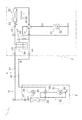
図1は、本発明の一実施形態に係る空気調和装置1の概略構成図である。空気調和装置1は、その冷媒回路10内に圧縮機を2つ、膨張弁を2つ有し、2段圧縮2段膨張冷凍サイクル運転を行うことによって、ビル等の室内の冷暖房に使用される装置である。空気調和装置1は、主として、1台の熱源ユニットとしての室外ユニット2と、それに接続された利用ユニットとしての室内ユニット3と、室外ユニット2と室内ユニット3とを接続する冷媒連絡配管4とを備えている。冷媒連絡配管4は、液冷媒連絡配管41とガス冷媒連絡配管42とから構成される。すなわち、本実施形態の空気調和装置1の冷媒回路10は、室外ユニット2と、室内ユニット3と、冷媒連絡配管4とが接続されることによって構成されている。
<Configuration of air conditioner>
FIG. 1 is a schematic configuration diagram of an air-
(1)室外ユニット
室外ユニット2は、ビル等の室外に設置されており、冷媒連絡配管4を介して室内ユニット3に接続されており、冷媒回路10を構成している。
(1) Outdoor unit The
次に、室外ユニット2の構成について説明する。室外ユニット2は、主として、冷媒回路10の一部を構成する室外側冷媒回路20を有している。この室外側冷媒回路20は、主として、室外圧縮機21と、室外四路切換弁V1と、熱源側熱交換器としての室外熱交換器23と、膨張機構としての室外膨張弁V2と、気液分離器24と、液側閉鎖弁V3と、ガス側閉鎖弁V4とを有している。
Next, the configuration of the
室外圧縮機21は、運転容量を可変することが可能な圧縮機であり、本実施形態において、インバータにより回転数Rmが制御されるモータ22によって駆動される容積式圧縮機である。この室外圧縮機21は、冷房運転の際には2段圧縮2段膨張冷凍サイクルの高段側の圧縮機となり、暖房運転の際には2段圧縮2段膨張冷凍サイクルの低段側の圧縮機となる。2段圧縮2段膨張冷凍サイクルについては後述する。本実施形態において、室外圧縮機21は、1台のみであるが、これに限定されず、室内ユニットの接続台数等に応じて、2台以上の圧縮機が並列に接続されていても良い。
The
室外四路切換弁V1は、室外熱交換器23を蒸発器およびガスクーラとして機能させるために設けられた弁である。室外四路切換弁V1は、室外熱交換器23と、室外圧縮機21の吸入側と、室外圧縮機21の吐出側と、ガス冷媒連絡配管42とに接続されている。そして、室外熱交換器23をガスクーラとして機能させる際には、室外圧縮機21の吐出側と室外熱交換器23とを接続するとともに、室外圧縮機21の吸入側とガス冷媒連絡配管42とを接続する(図1の実線の状態、冷房運転)。逆に、室外熱交換器23を蒸発器として機能させる際には、室外熱交換器23と室外圧縮機21の吸入側とを接続するとともに、室外圧縮機21の吐出側とガス冷媒連絡配管42とを接続する(図1の破線の状態、暖房運転)。
The outdoor four-way switching valve V1 is a valve provided to cause the
室外熱交換器23は、冷媒の蒸発器および冷媒のガスクーラとして機能させることが可能な熱交換器であり、本実施形態において、空気を熱源として冷媒と熱交換するクロスフィン式のフィン・アンド・チューブ型熱交換器である。室外熱交換器23は、一方が室外四路切換弁V1に接続され、他方が室外膨張弁V2を介して液冷媒連絡配管41に接続されている。
The
室外膨張弁V2は、室外側冷媒回路20内を流れる冷媒の圧力や流量等の調節を行うために、室外熱交換器23の液側に接続された電動膨張弁である。この室外膨張弁V2は、冷房運転の際には、2段圧縮2段膨張冷凍サイクルにおける1段目の膨張機構として機能し、暖房運転の際には、2段圧縮2段膨張冷凍サイクルにおける2段目の膨張機構として機能する。1段目の膨張機構として機能する際には、高圧Phの冷媒を中間圧力Pmに減圧させている。また、2段目の膨張機構として機能する際には、中間圧力Pmの冷媒を低圧Plに減圧させている。
The outdoor expansion valve V <b> 2 is an electric expansion valve connected to the liquid side of the
気液分離器24では、室外膨張弁V2または室内膨張弁V7(後述参照)で中間圧力Pmに減圧されて流入してきた気液二相状態の冷媒を液冷媒とガス冷媒とに分離して、液冷媒を溜めることが可能である。気液分離器24で溜められた液冷媒は、冷房運転時には室内膨張弁V7へ送られ、暖房運転時には室外膨張弁V2へ送られる。また、気液分離器24で分離されたガス冷媒は、ガス側閉鎖弁V4と室外四路切換弁V1との間の配管にバイパス回路27により接続されている。このバイパス回路27は、ガス冷媒の流量を制御可能なバイパス弁V5を備えている。
In the gas-
また、室外ユニット2は、ユニット内に室外空気を吸入して、室外熱交換器23において冷媒と熱交換させた後に、室外に排出するための送風ファンとしての室外ファン25を有している。この室外ファン25は、室外熱交換器23に供給する空気の風量を可変することが可能なファンであり、本実施形態において、DCファンモータからなるモータ26によって駆動されるプロペラファン等である。
The
(2)室内ユニット
室内ユニット3は、ビル等の室内の天井に埋め込みや吊り下げ等、または、室内の壁面に壁掛け等により設置されている。室内ユニット3は、冷媒連絡配管4を介して室外ユニット2に接続されており、冷媒回路10の一部を構成している。
(2) Indoor unit The
次に、室内ユニット3の構成について説明する。室内ユニット3は、主として、冷媒回路10の一部を構成する室内側冷媒回路30を有している。この室内側冷媒回路30は、主として、室内圧縮機31と、室内四路切換弁V5と、膨張機構としての室内膨張弁V7と、利用側熱交換器としての室内熱交換器33とを有している。
Next, the configuration of the
室内圧縮機31は、運転容量を可変することが可能な圧縮機であり、本実施形態において、インバータにより回転数Rmが制御されるモータ32によって駆動される容積式圧縮機である。この室内圧縮機31は、冷房運転の際には2段圧縮2段膨張冷凍サイクルの低段側の圧縮機となり、暖房運転の際には2段圧縮2段膨張冷凍サイクルの高段側の圧縮機となる。本実施形態において、室内圧縮機31は、インバータ制御による運転容量が可変のものを利用しているが、運転容量が固定のものでも良い。
The
室内四路切換弁V5は、室外四路切換弁V1と同様に、室内熱交換器33を蒸発器およびガスクーラとして機能させるために設けられた弁である。室内四路切換弁V5は、室内熱交換器33と、室内圧縮機31の吸入側と、室内圧縮機31の吐出側と、ガス冷媒連絡配管42とに接続されている。そして、室内熱交換器33をガスクーラとして機能させる際には、室内圧縮機31の吐出側と室内熱交換器33とを接続するとともに、室内圧縮機31の吸入側とガス冷媒連絡配管42とを接続する(図1の破線の状態)。逆に、室内熱交換器33を蒸発器として機能させる際には、室内熱交換器33と室内圧縮機31の吸入側とを接続するとともに、室内圧縮機31の吐出側とガス冷媒連絡配管42とを接続する(図1の実線の状態)。なお、室外四路切換弁V1と室内四路切換弁V5とは、次のように連動して機能する。室外四路切換弁V1が室外熱交換器23をガスクーラとして機能させる状態となっている場合に、室内四路切換弁V5は、室内熱交換器33を蒸発器として機能させる状態となる。また、室外四路切換弁V1が室外熱交換器23を蒸発器として機能させる状態となっている場合に、室内四路切換弁V5は、室内熱交換器33をガスクーラとして機能させる状態となる。
The indoor four-way switching valve V5 is a valve provided to cause the
室内膨張弁V7は、室外膨張弁V2と同様に、室内側冷媒回路30内を流れる冷媒の圧力や流量等の調節を行うために、室内熱交換器33の液側に接続された電動膨張弁である。この室内膨張弁V7は、冷房運転の際には、2段圧縮2段膨張冷凍サイクルにおける2段目の膨張機構として機能し、暖房運転の際には、2段圧縮2段膨張冷凍サイクルにおける1段目の膨張機構として機能する。この室内膨張弁V7も室外膨張弁V2と同様に、1段目の膨張機構として機能する際には、高圧Phの冷媒を中間圧力Pmに減圧させている。また、2段目の膨張機構として機能する際には、中間圧力Pmの冷媒を低圧Plに減圧させている。
Similarly to the outdoor expansion valve V2, the indoor expansion valve V7 is an electric expansion valve connected to the liquid side of the
室内熱交換器33は、伝熱管と多数のフィンとにより構成されたクロスフィン式のフィン・アンド・チューブ型熱交換器であり、冷房運転時には冷媒の蒸発器として機能して室内空気を冷却し、暖房運転時には冷媒のガスクーラとして機能して室内空気を加熱する熱交換器である。
The
また、室内ユニット3は、室内空気をユニット内に吸入して、室内熱交換器33において冷媒と熱交換させた後に、供給空気として室内に供給する送風ファンとしての室内ファン34を有している。室内ファン34は、室内熱交換器33に供給する空気の風量を可変することが可能なファンであり、本実施形態において、DCファンモータからなるモータ35によって駆動される遠心ファンや多翼ファン等である。
The
(3)冷媒連絡配管
冷媒連絡配管4は、空気調和装置1をビル等の設置場所に設置する際に、現地にて施工される冷媒配管であり、設置場所や室外ユニット2と室内ユニット3との組み合わせ等の設置条件に応じて種々の長さや管径を有するものが使用される。
(3) Refrigerant communication pipe The
<空気調和装置の動作>
次に、本実施形態の空気調和装置1の動作について説明する。
<Operation of air conditioner>
Next, operation | movement of the
本実施形態の空気調和装置1の運転モードとしては、室内ユニット3の冷暖房の負荷に応じて、室内ユニット3の冷房を行う冷房運転と、室内ユニット3の暖房を行う暖房運転とがある。
The operation mode of the
以下、空気調和装置1の各運転モードにおける動作について説明する。
Hereinafter, the operation | movement in each operation mode of the
(1)冷房運転
まず、冷房運転について、図1および図2を用いて説明する。冷房運転時は、室外ユニット2の室外側冷媒回路20において、室外四路切換弁V1が図1の実線で示される状態に切り換えられ、かつ、室内ユニット3の室内側冷媒回路30において、室内四路切換弁V5が図1の実線で示される状態に切り換えられることによって、室外熱交換器23がガスクーラとして機能し、かつ、室内熱交換器33が蒸発器として機能するようになっている。
(1) Cooling Operation First, the cooling operation will be described with reference to FIGS. 1 and 2. During the cooling operation, the outdoor four-way switching valve V1 in the outdoor
この冷媒回路10の状態で、室内圧縮機31、室外圧縮機21、室外ファン25、および室内ファン34を起動すると、低圧Plのガス冷媒は、室内圧縮機31に吸入されて圧縮されて中間圧力Pmのガス冷媒となる。その後、中間圧力Pmのガス冷媒は、室内四路切換弁V5を経由してガス冷媒連絡配管42に送られる。ガス冷媒連絡配管42に送られた中間圧力Pmのガス冷媒は、ガス側閉鎖弁V4から室外ユニット2内に流入する。室外ユニット2内に流入したガス冷媒は、バイパス回路27からの気液分離器24で分離されたガス冷媒(インジェクションガス)と合流して、室外四路切換弁V1を経由して室外圧縮機21に流入する。室外圧縮機21に流入したガス冷媒は、中間圧力Pmから高圧Phに圧縮され室外熱交換器23に流入する。このとき室外熱交換器23は、ガスクーラとして機能し室外ファン25によって供給される室外空気に熱を放出して冷媒を冷却する。そして、室外膨張弁V2により高圧Phの状態から中間圧力Pmまで減圧される。中間圧力Pmに減圧された冷媒は、気液二相状態となっており気液分離器24に流入する。気液分離器24では、液冷媒とガス冷媒とに分離して、中間圧力Pmの液冷媒を液側閉鎖弁V3側の配管へ流出し、中間圧力Pmのガス冷媒をバイパス回路27を介して室外圧縮機21の吸入側へ流出する。
When the
そして、中間圧力Pmの液冷媒は、液側閉鎖弁V3、液冷媒連絡配管41を経由して室内ユニット3に送られる。この室内ユニット3に送られた中間圧力Pmの液冷媒は、室内膨張弁V7によって室内圧縮機31の吸入圧力近くまで減圧されて低圧Plの気液二相状態の冷媒となって室内熱交換器33に送られ、室内熱交換器33において室内空気と熱交換を行って蒸発して低圧Plのガス冷媒となる。低圧Plのガス冷媒は、室内四路切換弁V5を経由して、再び、室内圧縮機31に吸入される。
Then, the liquid refrigerant at the intermediate pressure Pm is sent to the
(2)暖房運転
暖房運転時は、室外ユニット2の室外側冷媒回路20において、室外四路切換弁V1が図1の破線で示される状態に切り換えられ、かつ、室内ユニット3の室内側冷媒回路30において、室内四路切換弁V5が図1の破線で示される状態に切り換えられることによって、室外熱交換器23が蒸発器として機能し、かつ、室内熱交換器33がガスクーラとして機能するようになっている。
(2) Heating operation During the heating operation, in the outdoor
この冷媒回路10の状態で、室内圧縮機31、室外圧縮機21、室外ファン25、および室内ファン34を起動すると、低圧Plのガス冷媒は、室外圧縮機21に吸入されて圧縮されて中間圧力Pmのガス冷媒となり、室外四路切換弁V1を経由して、バイパス回路27からの気液分離器24で分離されたガス冷媒(インジェクションガス)と合流する。そして、合流した中間圧力Pmのガス冷媒は、ガス側閉鎖弁V4を経由して、ガス冷媒連絡配管42に送られる。
When the
そして、ガス冷媒連絡配管42に送られた中間圧力Pmのガス冷媒は、室内ユニット3に送られる。この室内ユニット3に送られた中間圧力Pmのガス冷媒は、室内圧縮機31において高温高圧の超臨界状態まで圧縮される。超臨界状態となった冷媒は、室内四路切換弁V5を経由して、室内熱交換器33に送られる。この冷媒は、室内熱交換器33において、室内空気と熱交換を行って冷却されて高圧Phの液冷媒となった後、室内膨張弁V7を通過する際に、室内膨張弁V7の弁開度に応じて中間圧力Pmまで減圧される。
Then, the gas refrigerant having the intermediate pressure Pm sent to the gas
そして、室内膨張弁V7を通過した冷媒は、液冷媒連絡配管41を経由して室外ユニット2に送られる。液側閉鎖弁V3を経由して室外ユニット2に流入した中間圧力Pmの冷媒は、気液二相状態となっており気液分離器24に流入する。気液分離器24では、液冷媒とガス冷媒とに分離して、中間圧力Pmの液冷媒を室外膨張弁V2側の配管へ流出し、中間圧力Pmのガス冷媒をバイパス回路27を介して室外圧縮機21の吸入側へ流出する。中間圧力Pmの液冷媒は、室外膨張弁V2を経由してさらに減圧されて低圧Plの液冷媒となった後に、室外熱交換器23に流入する。そして、室外熱交換器23に流入した低圧Plの気液二相状態の冷媒は、室外ファン25によって供給される室外空気と熱交換を行って蒸発して低圧Plのガス冷媒となり、室外四路切換弁V1を経由して、再び、室外圧縮機21に吸入される。
The refrigerant that has passed through the indoor expansion valve V <b> 7 is sent to the
<2段圧縮2段膨張冷凍サイクル>
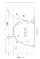
図2は、超臨界条件下における冷凍サイクルをp−h線図(モリエル線図)により示している。本発明では、冷媒に超臨界冷媒であるCO2冷媒を利用している。また、2台の圧縮機を用いて2段に分けて圧縮し、2つの膨張機構を用いて2段に分けて膨張させるようにした2段圧縮2段膨張冷凍サイクルを採用している。この2段圧縮2段膨張サイクルについて、図1および図2を用いて説明する。ここでは、前述の冷房運転の場合について説明する。前述のように、この冷媒回路10は、主に、室内圧縮機31、室外圧縮機21、室外熱交換器23、室外膨張弁V2、室内膨張弁V7、および室内熱交換器33から構成されている。図2のA1、B1、C1、D1、E1、F1、G1、H1、およびI1は、図1におけるそれぞれの点に対応した冷媒の状態を表している。
<Two-stage compression, two-stage expansion refrigeration cycle>
FIG. 2 shows a refrigeration cycle under supercritical conditions by a ph diagram (Mollier diagram). In the present invention, a CO2 refrigerant that is a supercritical refrigerant is used as the refrigerant. In addition, a two-stage compression and two-stage expansion refrigeration cycle is employed in which two compressors are used for compression in two stages and two expansion mechanisms are used for expansion in two stages. This two-stage compression / two-stage expansion cycle will be described with reference to FIGS. 1 and 2. Here, the case of the above-described cooling operation will be described. As described above, the
この冷媒回路10では、冷媒は、室内圧縮機31により圧縮されて高温中間圧力Pmになる(A1→B1)。中間圧力Pmまで圧縮された高温の冷媒は、中間圧力Pmのままガス冷媒連絡配管42を通過して、気液分離器24により分離された中間圧力Pmのガス冷媒(インジェクションガス)と合流し、冷却される(B1+I1→C1)。インジェクションガスと合流して冷却された中間圧力Pmのガス冷媒は、室外圧縮機21で圧縮されて高温高圧になる(C1→D1)。このとき、冷媒であるCO2は気体から超臨界状態となる。ここにいう「超臨界状態」とは、臨界点K以上の温度および圧力下における物質の状態であり、気体の拡散性と液体の溶解性とを併せ持っている状態のことである。超臨界状態とは、図2において、臨界温度等温線Tkの右側で、かつ、臨界圧力Pk以上の領域における冷媒の状態である。なお、冷媒(物質)が超臨界状態になると、気相と液相との区別が無くなる。なお、ここにいう「気相」とは、飽和蒸気線Svより右側で、かつ、臨界圧力Pk以下の領域における冷媒の状態である。また、「液相」とは、飽和液線Slより左側で、かつ、臨界温度等温線Tkよりも左側の領域における冷媒の状態である。そして、室外圧縮機21により圧縮されて高温高圧の超臨界状態となった冷媒は、ガスクーラとなっている室外熱交換器23により放熱されて低温高圧の冷媒となる(D1→E1)。このとき、冷媒は、超臨界状態にあるため、室外熱交換器23内部において顕熱変化(温度変化)を伴って作動している。そして、室外熱交換器23において放熱した冷媒は、室外膨張弁V2が開放されることにより膨張して、圧力が高圧Phから中間圧力Pmへと減圧される(E1→F1)。そして、室外膨張弁V2により減圧された冷媒は、気液二相状態となっており気液分離器24に流入する。気液分離器24では、液冷媒とガス冷媒とに分離する。そして、中間圧力Pmの液冷媒を液側閉鎖弁V3側の配管へ流出し(F1→G1)、中間圧力Pmのガス冷媒をバイパス回路27を介して室外圧縮機21の吸入側へ流出する(F1→I1)。中間圧力Pmの液冷媒は、液冷媒連絡配管41を通過し、室内膨張弁V7でさらに膨張されて低圧Plの液冷媒となる(G1→H1)。この低圧Plの液冷媒が、室内熱交換器33において、熱を吸収し、蒸発して室内圧縮機31へ戻る(H1→A1)。
In the
<特徴>
(1)
本実施例では、2段圧縮2段膨張冷凍サイクルを用いることで、冷媒連絡配管4が中間圧力Pmになるようにしている。すなわち、ガス冷媒連絡配管42を介して室外圧縮機21と室内圧縮機31とが接続されており、また、液冷媒連絡配管41を介して室外膨張弁V2と室内膨張弁V7とが接続されている。
<Features>
(1)
In this embodiment, the
したがって、室内ユニット3と室外ユニット2とを接続している冷媒連絡配管4内を通過する冷媒の圧力を中間圧力Pmにすることができ、設計圧力が高いCO2冷媒を用いても冷媒連絡配管4にあまり負荷がかからない程度の圧力に抑えることができる。
Therefore, the pressure of the refrigerant passing through the
(2)
本発明では、例えば、暖房運転と冷房運転とのような運転状態を切り替えることのできる室外四路切換弁V1と室内四路切換弁V5とが搭載されている。
(2)
In the present invention, for example, an outdoor four-way switching valve V1 and an indoor four-way switching valve V5 that can be switched between operating states such as heating operation and cooling operation are mounted.
したがって、室外四路切換弁V1と室内四路切換弁V5とは、室外熱交換器23を蒸発器として、かつ、室内熱交換器33をガスクーラとして利用することと、それとは逆に、室外熱交換器23をガスクーラとして、かつ、室内熱交換器33を蒸発器として利用するように切り替えることができる。これにより、室内ユニット3を冷房運転と暖房運転とに切り替えることができる。このため、外気温に応じて室内ユニット3の運転状態を切り替えることができ、快適な空調空間を提供することができる。
Therefore, the outdoor four-way switching valve V1 and the indoor four-way switching valve V5 use the
また、本発明では、室内ユニット3内にさらに室内四路切換弁V5を設けているため、室内四路切換弁V5の設置を容易にすることができる。
In the present invention, since the indoor four-way switching valve V5 is further provided in the
(3)
この空気調和装置1では、冷媒にCO2冷媒を利用している。CO2冷媒は、オゾン破壊係数が0のためオゾン層を破壊することがない。また、CO2冷媒は、地球温暖化係数が1であり、数百から1万程度のフルオロカーボン冷媒よりも遙かに低い。
(3)
In the
このため、CO2冷媒を利用することで、環境負荷が小さく、地球環境が悪化することを抑えることができる。 For this reason, by using CO2 refrigerant | coolant, it can suppress that an environmental load is small and global environment deteriorates.
<変形例>
(1)
本実施形態では、室内ユニット3が1台の室外ユニット2に対して1台接続されている、いわゆるペア式の空気調和装置1であるが、これに限らずに、複数台の室内ユニットが1台の室外ユニットに対して接続されているマルチ式の空気調和装置1aであっても良い。例えば、図3のように、1台の室外ユニット2に対して3台の室内ユニット3a,3b,3cが並列に接続されているものである。図3の室内ユニット3a,3b,3cの構成は、本実施形態で説明した室内ユニット3の各部に付した番号に、室内ユニット3a,3b,3cと対応するように、番号の末尾にa,b,およびcを付している。例えば、室内ユニット3の室内ファン34は、室内ユニット3a,3b,3cの室内ファン34a,34b,34cと対応しており、室内ユニット3と室内ユニット3a,3b,3cとは同様の構成である。なお、図3では室内ユニット3a〜3cは3台接続されているが、3台に限らずに、2台、4台、5台などであっても構わない。
<Modification>
(1)
In the present embodiment, the
室内ユニット3a〜3cを複数台設けているため、運転負荷が異なる箇所に対してそれぞれの負荷に応じて運転することができる。したがって、運転負荷が場所によって異なる場合に、室内ユニットが1台の場合よりも効率よく運転することができる。
Since a plurality of the
(2)
変形例(1)において図3のような空気調和装置1aでは、室内圧縮機31a〜31cが3台の室内ユニット3a〜3cにそれぞれ対応して、3台設けられているが、これに限らずに、例えば図4のように2台の室内ユニット5a,5bに並列に接続される1台の圧縮ユニット6を設けても良い。なお、この室内ユニット5a,5bは、室内熱交換器51a,51bと、モータ53a,53bによって駆動される室内ファン52a,52bと、室内膨張弁V9a,V9bとを有する。また、圧縮ユニット6は、モータ62によって駆動される容量可変の室内圧縮機61と、室内四路切換弁V5とを有する。この図4の例では室内ユニットは2台であるが、3台、4台、5台などでも構わない。
(2)
In the modified example (1), in the air conditioner 1a as shown in FIG. 3, three
(3)
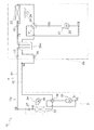
本実施形態では、室外膨張弁V2と室内膨張弁V7との間、および、室外圧縮機21と室内圧縮機31との間には、冷媒連絡配管4(液冷媒連絡配管41およびガス冷媒連絡配管42)がそのまま接続されているが、さらに、この間に中間冷却器24aを設けていてもよい。例えば、図4のように、室外ユニット2内に設けるようにしても良い。以下、中間冷却器24aを有する冷媒回路10cにおける冷凍サイクルについて説明する。
(3)
In the present embodiment, the refrigerant communication pipe 4 (the liquid
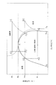
図5は、超臨界条件下における冷凍サイクルをp−h線図(モリエル線図)により示している。本発明では、冷媒に超臨界冷媒であるCO2冷媒を利用している。また、2台の圧縮機を用いて2段に分けて圧縮し、2つの膨張機構を用いて2段に分けて膨張するようにした2段圧縮2段膨張冷凍サイクルを採用している。この2段圧縮2段膨張サイクルについて、図4および図5を用いて説明する。ここでは、前述の冷房運転の場合について説明する。この冷媒回路10cは、主に、室内圧縮機31、室外圧縮機21、室外熱交換器23、室外膨張弁V2、中間冷却器24a、室内膨張弁V7、室内熱交換器33から構成されている。図2のA2、B2、C2、D2、E2、F2、G2、およびH2は、図5におけるそれぞれの点に対応した冷媒の状態を表している。なお、この場合の運転状態を冷房運転の場合について説明する。
FIG. 5 shows a refrigeration cycle under supercritical conditions by a ph diagram (Mollier diagram). In the present invention, a CO2 refrigerant that is a supercritical refrigerant is used as the refrigerant. In addition, a two-stage compression two-stage expansion refrigeration cycle is adopted in which two compressors are used to compress in two stages and two expansion mechanisms are used to expand in two stages. This two-stage compression / two-stage expansion cycle will be described with reference to FIGS. 4 and 5. Here, the case of the above-described cooling operation will be described. The
この冷媒回路10cでは、冷媒は、室内圧縮機31により圧縮されて高温中間圧力Pmになる(A2→B2)。中間圧力Pmまで圧縮された高温の冷媒は、中間冷却器24aに流入している。中間冷却器24aには、室外膨張弁V2で減圧されて中間圧力Pmになった液冷媒も流入している。また、この液冷媒と室内圧縮機31で圧縮されたガス冷媒と共存した状態となっており平衡状態になっている。過熱状態のガス冷媒は飽和状態もしくはそれに近い状態にまで冷却され過熱を除去される。(B2→C2)。中間冷却器24aで、過熱を除去されたガス冷媒は、室外圧縮機21で圧縮されて高温高圧になる(C2→D2)。このとき、冷媒であるCO2は気体から超臨界状態となる。そして、室外圧縮機21により圧縮されて高温高圧の超臨界状態となった冷媒は、ガスクーラとなっている室外熱交換器23により放熱されて低温高圧の冷媒となる(D2→E2)。このとき、冷媒は、超臨界状態にあるため、室外熱交換器23内部において顕熱変化(温度変化)を伴って作動している。そして、室外熱交換器23において放熱した冷媒は、室外膨張弁V2が開放されることにより膨張して、圧力が高圧Phから中間圧力PmのPmへと減圧される(E2→F2)。そして、室外膨張弁V2により減圧された冷媒は、中間冷却器24aに流入する。中間冷却器24aに流入した中間圧力Pmの冷媒は、その一部が蒸発して(F2→C2)中間冷却器24a内部の液冷媒を過冷却域まで冷却する(F2→G2)。このとき、同時に前述したB2→C2で行われているガス冷媒の過熱の除去も行っている。中間冷却器24a内で、残った中間圧力Pmの液冷媒は、室内膨張弁V7でさらに膨張されて低圧Plの液冷媒となる(G2→H2)。この低圧Plの液冷媒が、室内熱交換器33において、熱を吸収し、蒸発して室内圧縮機31へ戻る(H2→A2)。
In the
本発明では、室外ユニット2a内に中間圧力Pmの液冷媒とガス冷媒とを冷却する中間冷却器24aを有している。中間冷却器24aでは、室外膨張弁V2により中間圧力Pmに減圧された気液二相状態の冷媒と、室内圧縮機31により中間圧力Pmまで圧縮されたガス冷媒とが通過する。このとき、液冷媒の一部を蒸発させて中間冷却器24a内部の冷媒に冷凍効果を付与している。
In this invention, it has the intermediate cooler 24a which cools the liquid refrigerant and intermediate | middle pressure Pm in the outdoor unit 2a. In the intermediate cooler 24a, the gas-liquid two-phase refrigerant decompressed to the intermediate pressure Pm by the outdoor expansion valve V2 and the gas refrigerant compressed to the intermediate pressure Pm by the
したがって、室内圧縮機31で圧縮された中間圧力Pmのガス冷媒を飽和状態もしくはそれに近い状態にまで冷却することができる。また、液冷媒にも同様に冷凍効果により過冷却域まで冷却することができる。これにより、このサイクル全体の冷凍効果を上げることができる。また、室外圧縮機21の吐出温度を下げることができ、室外圧縮機21の潤滑油の劣化を防ぐことができる。前述では、冷房運転時のみ説明したが暖房運転の際にも同様の効果がある。
Therefore, the gas refrigerant having the intermediate pressure Pm compressed by the
(4)
本実施形態では、膨張機構として室外ユニット2内に室外膨張弁V2を設け、室内ユニット3内に室内膨張弁V7を設けているが、これらの膨張弁に限らずに、例えば膨張機などでも構わない。
(4)
In this embodiment, the outdoor expansion valve V2 is provided in the
本発明に係る空気調和装置は、更新工事の際に、既設の冷媒連絡配管をそのまま利用できるためコストを削減することができ、CO2冷媒などの冷媒を用いて運転されるような設計圧力が高い空気調和装置等に有用である。 The air conditioner according to the present invention can reduce the cost because the existing refrigerant communication pipe can be used as it is at the time of renewal work, and the design pressure is high so that it can be operated using a refrigerant such as a CO2 refrigerant. Useful for air conditioners and the like.
1,1a〜1c 空気調和装置
2,2a 室外ユニット(熱源ユニット)
3,3a〜3c 室内ユニット(利用ユニット)
5a,5b 室内ユニット(利用ユニット)
21 室外圧縮機(第1圧縮機)
24a 中間冷却器
31,31a〜31c 室内圧縮機(第2圧縮機)
41 液冷媒連絡配管
42 ガス冷媒連絡配管
51a,51b 室内熱交換器
61 室内圧縮機(第2圧縮機)
V1 室外四路切換弁(第1切換機構)
V2 室外膨張弁(熱源側膨張機構)
V5,V5a〜V5c 室内四路切換弁(第2切換機構)
V7,V7a〜V7c 室内膨張弁(利用側膨張機構)
V8 室内四路切換弁(第2切換機構)
V9a,V9b 室内膨張弁(利用側膨張機構)
1, 1a-
3,3a-3c Indoor unit (Usage unit)
5a, 5b Indoor unit (Usage unit)
21 Outdoor compressor (first compressor)
41 Liquid
V1 outdoor four-way switching valve (first switching mechanism)
V2 outdoor expansion valve (heat source side expansion mechanism)
V5, V5a to V5c Indoor four-way switching valve (second switching mechanism)
V7, V7a-V7c Indoor expansion valve (use side expansion mechanism)
V8 indoor four-way switching valve (second switching mechanism)
V9a, V9b Indoor expansion valve (use side expansion mechanism)
Claims (5)
前記冷媒を圧縮する第1圧縮機(21)と、前記冷媒を熱交換させる熱源側熱交換器(23)と、前記冷媒を減圧する熱源側膨張機構(V2)とを有する熱源ユニット(2,2a)と、
前記冷媒を圧縮する第2圧縮機(31,31a〜31c,61)と、前記冷媒を熱交換させる利用側熱交換器(33,33a〜33c)と、前記冷媒を減圧する利用側膨張機構(V7,V7a〜V7c,V9a,V9b)とを有する利用ユニット(3,3a〜3c,5a,5b)と、
前記第1圧縮機から前記第2圧縮機へ延びるガス冷媒連絡配管(42)と、
前記熱源側膨張機構から前記利用側膨張機構へ延びる液冷媒連絡配管(41)と、
を備え、
前記ガス冷媒連絡配管は、前記第1圧縮機または前記第2圧縮機で低圧から中間圧力まで圧縮された前記冷媒を流通させ、
前記液冷媒連絡配管は、前記利用側膨張機構または前記熱源側膨張機構で高圧から中間圧力まで減圧された前記冷媒を流通させる、
空気調和装置(1,1a〜1c)。 An air conditioner using a supercritical refrigerant,
A heat source unit (2,) having a first compressor (21) for compressing the refrigerant, a heat source side heat exchanger (23) for exchanging heat of the refrigerant, and a heat source side expansion mechanism (V2) for depressurizing the refrigerant. 2a)
A second compressor (31, 31a to 31c, 61) that compresses the refrigerant, a use side heat exchanger (33, 33a to 33c) that exchanges heat of the refrigerant, and a use side expansion mechanism (decompressing the refrigerant) V7, V7a to V7c, V9a, V9b) and usage units (3, 3a to 3c, 5a, 5b),
A gas refrigerant communication pipe (42) extending from the first compressor to the second compressor;
A liquid refrigerant communication pipe (41) extending from the heat source side expansion mechanism to the use side expansion mechanism;
With
The gas refrigerant communication pipe distributes the refrigerant compressed from a low pressure to an intermediate pressure in the first compressor or the second compressor,
The liquid refrigerant communication pipe circulates the refrigerant decompressed from a high pressure to an intermediate pressure by the use side expansion mechanism or the heat source side expansion mechanism.
Air conditioner (1, 1a-1c).
請求項1に記載の空気調和装置(1c)。 The heat source unit further includes an intercooler (24a),
The air conditioner (1c) according to claim 1.
前記利用ユニットは、前記利用側熱交換器で蒸発された低圧の前記冷媒が前記第2圧縮機に流入し、かつ、前記第2圧縮機で中間圧力まで圧縮された前記冷媒が前記第1圧縮機に流入する第3状態と、前記第1圧縮機で中間圧力まで圧縮された前記冷媒が前記第2圧縮機に流入し、かつ、前記第2圧縮機で高圧まで圧縮された前記冷媒が前記利用側熱交換器に流入する第4状態とを切換可能である第2切換機構(V6,V6a〜V6c,V8)をさらに有し、
前記第1切換機構と前記第2切換機構とは、前記第1切換機構が前記第1状態になると前記第2切換機構が前記第3状態になり、前記第1切換機構が前記第2状態になると前記第2切換機構が前記第4状態になる、
請求項1から3のいずれかに記載の空気調和装置(1,1a〜1c)。 In the heat source unit, the refrigerant compressed to an intermediate pressure by the second compressor flows into the first compressor, and the refrigerant compressed to a high pressure by the first compressor exchanges the heat source side heat. The first state flowing into the storage unit, and the low-pressure refrigerant evaporated in the heat source side heat exchanger flows into the first compressor, and the refrigerant compressed to the intermediate pressure in the first compressor A first switching mechanism (V1) capable of switching between a second state flowing into the second compressor;
In the utilization unit, the low-pressure refrigerant evaporated in the utilization-side heat exchanger flows into the second compressor, and the refrigerant compressed to the intermediate pressure in the second compressor is in the first compression. A third state flowing into the machine, and the refrigerant compressed to an intermediate pressure by the first compressor flows into the second compressor and the refrigerant compressed to a high pressure by the second compressor is A second switching mechanism (V6, V6a to V6c, V8) capable of switching between the fourth state flowing into the use side heat exchanger;
The first switching mechanism and the second switching mechanism are configured such that when the first switching mechanism is in the first state, the second switching mechanism is in the third state, and the first switching mechanism is in the second state. Then, the second switching mechanism is in the fourth state,
The air conditioner (1, 1a to 1c) according to any one of claims 1 to 3.
請求項1から3のいずれかに記載の空気調和装置(1a,1b)。 A plurality of the use units (3a to 3c, 5a, 5b) are provided.
The air conditioner (1a, 1b) according to any one of claims 1 to 3.
請求項1から4のいずれかに記載の空気調和装置。 The supercritical refrigerant is a CO2 refrigerant.
The air conditioning apparatus according to any one of claims 1 to 4.
Priority Applications (1)
| Application Number | Priority Date | Filing Date | Title |
|---|---|---|---|
| JP2006314492A JP2008128564A (en) | 2006-11-21 | 2006-11-21 | Air conditioner |
Applications Claiming Priority (1)
| Application Number | Priority Date | Filing Date | Title |
|---|---|---|---|
| JP2006314492A JP2008128564A (en) | 2006-11-21 | 2006-11-21 | Air conditioner |
Publications (1)
| Publication Number | Publication Date |
|---|---|
| JP2008128564A true JP2008128564A (en) | 2008-06-05 |
Family
ID=39554573
Family Applications (1)
| Application Number | Title | Priority Date | Filing Date |
|---|---|---|---|
| JP2006314492A Pending JP2008128564A (en) | 2006-11-21 | 2006-11-21 | Air conditioner |
Country Status (1)
| Country | Link |
|---|---|
| JP (1) | JP2008128564A (en) |
-
2006
- 2006-11-21 JP JP2006314492A patent/JP2008128564A/en active Pending
Similar Documents
| Publication | Publication Date | Title |
|---|---|---|
| CN101535735B (en) | Air conditioner | |
| CN102095267B (en) | Air conditioning apparatus | |
| JP5871959B2 (en) | Air conditioner | |
| JP4167196B2 (en) | Natural circulation combined use air conditioner and natural circulation combined use air conditioner control method | |
| JP5049888B2 (en) | Refrigeration cycle equipment | |
| JP5908183B1 (en) | Air conditioner | |
| JP5049889B2 (en) | Refrigeration equipment | |
| WO2003001129A1 (en) | Freezing device | |
| JP2005249384A (en) | Refrigerating cycle device | |
| JP5895662B2 (en) | Refrigeration equipment | |
| JP2006308207A (en) | Refrigeration equipment | |
| JP4651452B2 (en) | Refrigeration air conditioner | |
| JP4192904B2 (en) | Refrigeration cycle equipment | |
| JP7343764B2 (en) | air conditioner | |
| WO2023067807A1 (en) | Binary refrigeration device | |
| JP2008128564A (en) | Air conditioner | |
| JP2008241205A (en) | Air conditioner | |
| JP2008164225A (en) | Receiver and refrigeration equipment |