EP2093446A2 - Conducteur de commande d'un véhicule de sport motorisé - Google Patents
Conducteur de commande d'un véhicule de sport motorisé Download PDFInfo
- Publication number
- EP2093446A2 EP2093446A2 EP09153191A EP09153191A EP2093446A2 EP 2093446 A2 EP2093446 A2 EP 2093446A2 EP 09153191 A EP09153191 A EP 09153191A EP 09153191 A EP09153191 A EP 09153191A EP 2093446 A2 EP2093446 A2 EP 2093446A2
- Authority
- EP
- European Patent Office
- Prior art keywords
- drive train
- shaped
- train according
- rod
- clutch basket
- Prior art date
- Legal status (The legal status is an assumption and is not a legal conclusion. Google has not performed a legal analysis and makes no representation as to the accuracy of the status listed.)
- Withdrawn
Links
Images

Classifications
-
- B—PERFORMING OPERATIONS; TRANSPORTING
- B60—VEHICLES IN GENERAL
- B60K—ARRANGEMENT OR MOUNTING OF PROPULSION UNITS OR OF TRANSMISSIONS IN VEHICLES; ARRANGEMENT OR MOUNTING OF PLURAL DIVERSE PRIME-MOVERS IN VEHICLES; AUXILIARY DRIVES FOR VEHICLES; INSTRUMENTATION OR DASHBOARDS FOR VEHICLES; ARRANGEMENTS IN CONNECTION WITH COOLING, AIR INTAKE, GAS EXHAUST OR FUEL SUPPLY OF PROPULSION UNITS IN VEHICLES
- B60K6/00—Arrangement or mounting of plural diverse prime-movers for mutual or common propulsion, e.g. hybrid propulsion systems comprising electric motors and internal combustion engines ; Control systems therefor, i.e. systems controlling two or more prime movers, or controlling one of these prime movers and any of the transmission, drive or drive units Informative references: mechanical gearings with secondary electric drive F16H3/72; arrangements for handling mechanical energy structurally associated with the dynamo-electric machine H02K7/00; machines comprising structurally interrelated motor and generator parts H02K51/00; dynamo-electric machines not otherwise provided for in H02K see H02K99/00
- B60K6/20—Arrangement or mounting of plural diverse prime-movers for mutual or common propulsion, e.g. hybrid propulsion systems comprising electric motors and internal combustion engines ; Control systems therefor, i.e. systems controlling two or more prime movers, or controlling one of these prime movers and any of the transmission, drive or drive units Informative references: mechanical gearings with secondary electric drive F16H3/72; arrangements for handling mechanical energy structurally associated with the dynamo-electric machine H02K7/00; machines comprising structurally interrelated motor and generator parts H02K51/00; dynamo-electric machines not otherwise provided for in H02K see H02K99/00 the prime-movers consisting of electric motors and internal combustion engines, e.g. HEVs
- B60K6/22—Arrangement or mounting of plural diverse prime-movers for mutual or common propulsion, e.g. hybrid propulsion systems comprising electric motors and internal combustion engines ; Control systems therefor, i.e. systems controlling two or more prime movers, or controlling one of these prime movers and any of the transmission, drive or drive units Informative references: mechanical gearings with secondary electric drive F16H3/72; arrangements for handling mechanical energy structurally associated with the dynamo-electric machine H02K7/00; machines comprising structurally interrelated motor and generator parts H02K51/00; dynamo-electric machines not otherwise provided for in H02K see H02K99/00 the prime-movers consisting of electric motors and internal combustion engines, e.g. HEVs characterised by apparatus, components or means specially adapted for HEVs
- B60K6/40—Arrangement or mounting of plural diverse prime-movers for mutual or common propulsion, e.g. hybrid propulsion systems comprising electric motors and internal combustion engines ; Control systems therefor, i.e. systems controlling two or more prime movers, or controlling one of these prime movers and any of the transmission, drive or drive units Informative references: mechanical gearings with secondary electric drive F16H3/72; arrangements for handling mechanical energy structurally associated with the dynamo-electric machine H02K7/00; machines comprising structurally interrelated motor and generator parts H02K51/00; dynamo-electric machines not otherwise provided for in H02K see H02K99/00 the prime-movers consisting of electric motors and internal combustion engines, e.g. HEVs characterised by apparatus, components or means specially adapted for HEVs characterised by the assembly or relative disposition of components
-
- B—PERFORMING OPERATIONS; TRANSPORTING
- B60—VEHICLES IN GENERAL
- B60K—ARRANGEMENT OR MOUNTING OF PROPULSION UNITS OR OF TRANSMISSIONS IN VEHICLES; ARRANGEMENT OR MOUNTING OF PLURAL DIVERSE PRIME-MOVERS IN VEHICLES; AUXILIARY DRIVES FOR VEHICLES; INSTRUMENTATION OR DASHBOARDS FOR VEHICLES; ARRANGEMENTS IN CONNECTION WITH COOLING, AIR INTAKE, GAS EXHAUST OR FUEL SUPPLY OF PROPULSION UNITS IN VEHICLES
- B60K6/00—Arrangement or mounting of plural diverse prime-movers for mutual or common propulsion, e.g. hybrid propulsion systems comprising electric motors and internal combustion engines ; Control systems therefor, i.e. systems controlling two or more prime movers, or controlling one of these prime movers and any of the transmission, drive or drive units Informative references: mechanical gearings with secondary electric drive F16H3/72; arrangements for handling mechanical energy structurally associated with the dynamo-electric machine H02K7/00; machines comprising structurally interrelated motor and generator parts H02K51/00; dynamo-electric machines not otherwise provided for in H02K see H02K99/00
- B60K6/20—Arrangement or mounting of plural diverse prime-movers for mutual or common propulsion, e.g. hybrid propulsion systems comprising electric motors and internal combustion engines ; Control systems therefor, i.e. systems controlling two or more prime movers, or controlling one of these prime movers and any of the transmission, drive or drive units Informative references: mechanical gearings with secondary electric drive F16H3/72; arrangements for handling mechanical energy structurally associated with the dynamo-electric machine H02K7/00; machines comprising structurally interrelated motor and generator parts H02K51/00; dynamo-electric machines not otherwise provided for in H02K see H02K99/00 the prime-movers consisting of electric motors and internal combustion engines, e.g. HEVs
- B60K6/22—Arrangement or mounting of plural diverse prime-movers for mutual or common propulsion, e.g. hybrid propulsion systems comprising electric motors and internal combustion engines ; Control systems therefor, i.e. systems controlling two or more prime movers, or controlling one of these prime movers and any of the transmission, drive or drive units Informative references: mechanical gearings with secondary electric drive F16H3/72; arrangements for handling mechanical energy structurally associated with the dynamo-electric machine H02K7/00; machines comprising structurally interrelated motor and generator parts H02K51/00; dynamo-electric machines not otherwise provided for in H02K see H02K99/00 the prime-movers consisting of electric motors and internal combustion engines, e.g. HEVs characterised by apparatus, components or means specially adapted for HEVs
- B60K6/26—Arrangement or mounting of plural diverse prime-movers for mutual or common propulsion, e.g. hybrid propulsion systems comprising electric motors and internal combustion engines ; Control systems therefor, i.e. systems controlling two or more prime movers, or controlling one of these prime movers and any of the transmission, drive or drive units Informative references: mechanical gearings with secondary electric drive F16H3/72; arrangements for handling mechanical energy structurally associated with the dynamo-electric machine H02K7/00; machines comprising structurally interrelated motor and generator parts H02K51/00; dynamo-electric machines not otherwise provided for in H02K see H02K99/00 the prime-movers consisting of electric motors and internal combustion engines, e.g. HEVs characterised by apparatus, components or means specially adapted for HEVs characterised by the motors or the generators
-
- F—MECHANICAL ENGINEERING; LIGHTING; HEATING; WEAPONS; BLASTING
- F16—ENGINEERING ELEMENTS AND UNITS; GENERAL MEASURES FOR PRODUCING AND MAINTAINING EFFECTIVE FUNCTIONING OF MACHINES OR INSTALLATIONS; THERMAL INSULATION IN GENERAL
- F16D—COUPLINGS FOR TRANSMITTING ROTATION; CLUTCHES; BRAKES
- F16D13/00—Friction clutches
- F16D13/58—Details
- F16D13/60—Clutching elements
- F16D13/64—Clutch-plates; Clutch-lamellae
- F16D13/68—Attachments of plates or lamellae to their supports
- F16D13/683—Attachments of plates or lamellae to their supports for clutches with multiple lamellae
-
- B—PERFORMING OPERATIONS; TRANSPORTING
- B60—VEHICLES IN GENERAL
- B60Y—INDEXING SCHEME RELATING TO ASPECTS CROSS-CUTTING VEHICLE TECHNOLOGY
- B60Y2200/00—Type of vehicle
- B60Y2200/10—Road Vehicles
- B60Y2200/11—Passenger cars; Automobiles
- B60Y2200/114—Racing vehicles, e.g. Formula one, Karts
Definitions
- the invention relates to a drive train of a motor sport vehicle having a clutch which comprises a clutch basket, wherein the clutch basket has a number of extending in the direction of its axis of rotation rod-shaped elements.
- the invention has the object of providing a drive train of the type mentioned in such a way that it is possible to integrate an electric motor for a hybrid drive in him, without the required space, in particular the radial space significantly increased and without that the mass moment of inertia of the drive train increases. Furthermore, the electric motor to be integrated should be as light as possible.
- the solution of this problem by the invention is characterized in that the rod-shaped elements of the coupling basket are mechanically and electrically connected in its two axial ends via two ring-shaped or disk-shaped closing elements, wherein the clutch basket is surrounded by a stator coaxial with the axis of rotation.
- the clutch basket of the clutch which is commonly used as such, so converted that it also acts as a rotor of an electric motor. It is configured as indicated and surrounded coaxially by a stator.
- the stator and the clutch basket accordingly form an electric motor, preferably an asynchronous electric motor.
- the asynchronous motor can - as usual - include a frequency converter.
- the stator preferably has three pairs of electrical windings.
- the clutch basket advantageously has between eight and twelve rod-shaped elements; these are usually arranged equidistantly distributed around the circumference of the clutch basket.
- the rod-shaped elements made of steel.
- the ring-shaped or disc-shaped closing elements can also be made of steel. This achieves better electrical conductivity, which is what matters here.
- One of the ring-shaped or disc-shaped end elements and the rod-shaped elements may be formed in one piece.
- the other ring-shaped or disk-shaped closing element and the rod-shaped elements can be screwed together.
- the invention proposal is mainly used in a race car, including a Formula 1 car can be understood.
- the proposed design makes it possible to integrate an electric motor for the purpose of hybrid drive in a motor sport vehicle, without the mass moment of inertia of the drive train is increased. Also required for the electric motor additional weight remains in subordinate areas, since the clutch basket is the rotor of the electric motor and thus far no additional weight is due. Only the stator is additively added.
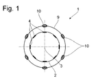
- Fig. 1 is the schematic structure of an electric motor to see how it is used according to the invention to equip a motor sports car for the hybrid drive.
- a coupling 1 seen in the direction of the axis of rotation 3 of the same, which consists of a rotatably mounted clutch basket 2 with foot housing, which is coaxial with the axis of rotation 3 surrounded by a stator 9.
- the clutch basket 2 has a number of rod-shaped elements 4, which extend in the direction of the axis of rotation 3.
- the clutch basket 2 In the axial ends 5 and 6 of the clutch basket 2 is ever a ring or disc-shaped end element 7 and 8 respectively. It is essential that the ring-shaped or disc-shaped end elements 7, 8 together with the rod-shaped elements 4 form a mechanically strong and electrically conductive connection. This is necessary to make the clutch basket 2 suitable as a rotor of the electric motor.
- the one disc-shaped end element 7 and the rod-shaped elements 4 carried out in one piece, ie in the present case worked from a steel blank by milling.
- the annular end element 8 is attached to the right end faces of the rod-shaped elements 4 and fixed by means of screws 11.
- the rotor 2 Coaxially with the axis of rotation 3, the rotor 2, ie the clutch basket, is surrounded by the stator 9.
- a total of three pairs of electrical windings 10 (coil pairs) are arranged around the circumference of the stator 9.
- the illustrated arrangement according to Fig. 1 works as an asynchronous motor with frequency converter, as it is well known as an electric drive.
- the stator 9 of this asynchronous motor thus consists of 3 pairs of windings, which are fed with one of the three phases of the three-phase current.
- the rotor 4 however, consists only of the electrically conductive rods 4, which are arranged parallel to the axis of rotation 3 of the motor or the clutch 1 to a defined diameter and which are electrically and mechanically connected at their ends.
- the rotating field generated by the stator 9 induces a current during the overhaul of the rotor in the bars 4, which in turn generates a stator-own magnetic field.
- the thus equipped vehicle can therefore be operated in hybrid mode.
- the clutch basket 2 is in this or similar form an already existing component and can be used in its form without changes for the said use, including the required storage, which also already exists.
- the efficiency of the rotor is improved when using steel rather than titanium because of the better conductivity of steel.
- stator Only the stator must be additionally housed in the vehicle in the implementation of the proposed invention. However, it does not increase the mass moment of inertia of the drive train.
Applications Claiming Priority (2)
| Application Number | Priority Date | Filing Date | Title |
|---|---|---|---|
| DE102008010900 | 2008-02-23 | ||
| DE102009000207A DE102009000207A1 (de) | 2008-02-23 | 2009-01-14 | Antriebsstrang eines Motorsportfahrzeugs |
Publications (2)
| Publication Number | Publication Date |
|---|---|
| EP2093446A2 true EP2093446A2 (fr) | 2009-08-26 |
| EP2093446A3 EP2093446A3 (fr) | 2010-12-15 |
Family
ID=40433844
Family Applications (1)
| Application Number | Title | Priority Date | Filing Date |
|---|---|---|---|
| EP09153191A Withdrawn EP2093446A3 (fr) | 2008-02-23 | 2009-02-19 | Conducteur de commande d'un véhicule de sport motorisé |
Country Status (1)
| Country | Link |
|---|---|
| EP (1) | EP2093446A3 (fr) |
Cited By (2)
| Publication number | Priority date | Publication date | Assignee | Title |
|---|---|---|---|---|
| WO2015139697A3 (fr) * | 2014-03-17 | 2016-01-14 | Schaeffler Technologies AG & Co. KG | Porte-lamelles et dispositif d'accouplement équipé d'un tel porte-lamelles |
| AT520016A1 (de) * | 2017-04-21 | 2018-12-15 | Miba Frictec Gmbh | Lamellenträger |
Citations (5)
| Publication number | Priority date | Publication date | Assignee | Title |
|---|---|---|---|---|
| DE3927776A1 (de) * | 1988-08-25 | 1990-03-01 | Zahnradfabrik Friedrichshafen | Kupplungs- oder bremslamellenpaket mit spreizvorrichtungen |
| DE19827339A1 (de) * | 1998-06-19 | 1999-12-30 | Sachs Race Eng Gmbh | Gehäuse für eine Lamellenkupplung |
| US6058591A (en) * | 1997-03-19 | 2000-05-09 | Koppy Corporation | Clutch drum and method of manufacture |
| DE10147099A1 (de) * | 2000-09-26 | 2002-05-08 | Aisin Aw Co | Verfahren und Vorrichtung zur Herstellung eines zylindrischen Teils und zylindrisches Teil mit Keilen |
| US20060065506A1 (en) * | 2004-09-29 | 2006-03-30 | Means Industries, Inc. | Drum assembly for a coupling arrangement |
-
2009
- 2009-02-19 EP EP09153191A patent/EP2093446A3/fr not_active Withdrawn
Patent Citations (5)
| Publication number | Priority date | Publication date | Assignee | Title |
|---|---|---|---|---|
| DE3927776A1 (de) * | 1988-08-25 | 1990-03-01 | Zahnradfabrik Friedrichshafen | Kupplungs- oder bremslamellenpaket mit spreizvorrichtungen |
| US6058591A (en) * | 1997-03-19 | 2000-05-09 | Koppy Corporation | Clutch drum and method of manufacture |
| DE19827339A1 (de) * | 1998-06-19 | 1999-12-30 | Sachs Race Eng Gmbh | Gehäuse für eine Lamellenkupplung |
| DE10147099A1 (de) * | 2000-09-26 | 2002-05-08 | Aisin Aw Co | Verfahren und Vorrichtung zur Herstellung eines zylindrischen Teils und zylindrisches Teil mit Keilen |
| US20060065506A1 (en) * | 2004-09-29 | 2006-03-30 | Means Industries, Inc. | Drum assembly for a coupling arrangement |
Non-Patent Citations (1)
| Title |
|---|
| ELLERS C W: "AUTOMATIC HYBRID ELECTRIC LUMINA VAN" WESCON TECHNICAL PAPERS, WESTERN PERIODICALS CO. NORTH HOLLYWOOD, US, 7. November 1995 (1995-11-07), Seiten 562-565, XP000586618 * |
Cited By (4)
| Publication number | Priority date | Publication date | Assignee | Title |
|---|---|---|---|---|
| WO2015139697A3 (fr) * | 2014-03-17 | 2016-01-14 | Schaeffler Technologies AG & Co. KG | Porte-lamelles et dispositif d'accouplement équipé d'un tel porte-lamelles |
| AT520016A1 (de) * | 2017-04-21 | 2018-12-15 | Miba Frictec Gmbh | Lamellenträger |
| AT520016B1 (de) * | 2017-04-21 | 2019-02-15 | Miba Frictec Gmbh | Lamellenträger |
| DE102018003093B4 (de) * | 2017-04-21 | 2020-10-22 | Miba Frictec Gmbh | Lamellenträger |
Also Published As
| Publication number | Publication date |
|---|---|
| EP2093446A3 (fr) | 2010-12-15 |
Similar Documents
| Publication | Publication Date | Title |
|---|---|---|
| EP2638618A2 (fr) | Moteur électrique à entrefer plan et vélo électrique ou vélo à assistance électrique équipé d'un moteur électrique à entrefer plan | |
| DE102010045777A1 (de) | Fahrmotor für Elektrofahrzeuge | |
| DE102011116586A1 (de) | Motor | |
| DE102010029248A1 (de) | Lenkantrieb für ein Kraftfahrzeug | |
| DE102013206593A1 (de) | xialflussmaschine in Leichtbauweise | |
| DE102016207996A1 (de) | Elektrische Maschine zum Antrieb eines Fahrzeugs | |
| DE102012100332A1 (de) | Stator für eine rotierende elektrische Maschine und Verfahren zu seiner Herstellung | |
| DE102009055396A1 (de) | Elektrischer Antrieb mit Schneckengetriebe | |
| EP2550721B1 (fr) | Machine électrique et dispositif de direction | |
| EP2148407A1 (fr) | Machine synchrone à aimants permanents | |
| EP3989408A1 (fr) | Rotor pour une machine électrique, machine électrique pour un véhicule et procédé de fabrication d'un rotor pour une machine électrique | |
| DE2425135A1 (de) | 6-poliger permanentmagnetischer elektromotor | |
| DE112013001643T5 (de) | Elektrische rotierende Maschine | |
| DE102007001828A1 (de) | Getriebeeinrichtung mit einem inneren und einem äußeren Rotorteil, welche von einem inneren und einem äußeren Statorteil umgeben sind | |
| DE102017004228A1 (de) | Rotierende elektrische Maschine mit erhöhter Leistung | |
| EP2093446A2 (fr) | Conducteur de commande d'un véhicule de sport motorisé | |
| DE102020107634A1 (de) | Axialflussmaschine mit taumelndem rotor | |
| DE102020116423A1 (de) | Rotor und elektromechanischer Energiewandler mit toroidaler Erregerspule und Kraftfahrzeug | |
| DE102017127611A1 (de) | Synchron-Reluktanzmotor mit durch Permanentmagnete gesättigtem magnetischen Nebenschlusspfad | |
| WO2018099632A1 (fr) | Rotor conçu pour un moteur électrique lspm | |
| DE102011055766A1 (de) | Drehstrom-Synchronmaschine | |
| DE102009000207A1 (de) | Antriebsstrang eines Motorsportfahrzeugs | |
| EP1758229B1 (fr) | Moteur électrique | |
| DE102015218304B3 (de) | Elektrische Maschine mit hoch drehzahlfestem Rotor | |
| DE102013219309A1 (de) | Baukastensystem und Verfahren zur Herstellung einer Elektromaschine |
Legal Events
| Date | Code | Title | Description |
|---|---|---|---|
| PUAI | Public reference made under article 153(3) epc to a published international application that has entered the european phase |
Free format text: ORIGINAL CODE: 0009012 |
|
| AK | Designated contracting states |
Kind code of ref document: A2 Designated state(s): AT BE BG CH CY CZ DE DK EE ES FI FR GB GR HR HU IE IS IT LI LT LU LV MC MK MT NL NO PL PT RO SE SI SK TR |
|
| AX | Request for extension of the european patent |
Extension state: AL BA RS |
|
| PUAL | Search report despatched |
Free format text: ORIGINAL CODE: 0009013 |
|
| AK | Designated contracting states |
Kind code of ref document: A3 Designated state(s): AT BE BG CH CY CZ DE DK EE ES FI FR GB GR HR HU IE IS IT LI LT LU LV MC MK MT NL NO PL PT RO SE SI SK TR |
|
| AX | Request for extension of the european patent |
Extension state: AL BA RS |
|
| 17P | Request for examination filed |
Effective date: 20110610 |
|
| AKX | Designation fees paid |
Designated state(s): AT BE BG CH CY CZ DE DK EE ES FI FR GB GR HR HU IE IS IT LI LT LU LV MC MK MT NL NO PL PT RO SE SI SK TR |
|
| GRAP | Despatch of communication of intention to grant a patent |
Free format text: ORIGINAL CODE: EPIDOSNIGR1 |
|
| STAA | Information on the status of an ep patent application or granted ep patent |
Free format text: STATUS: THE APPLICATION IS DEEMED TO BE WITHDRAWN |
|
| 18D | Application deemed to be withdrawn |
Effective date: 20120119 |