EP2093359B1 - Dispositif de verrouillage étanche d'un panneau monté à pivotement sur un axe, dans une embrasure - Google Patents
Dispositif de verrouillage étanche d'un panneau monté à pivotement sur un axe, dans une embrasure Download PDFInfo
- Publication number
- EP2093359B1 EP2093359B1 EP20080101898 EP08101898A EP2093359B1 EP 2093359 B1 EP2093359 B1 EP 2093359B1 EP 20080101898 EP20080101898 EP 20080101898 EP 08101898 A EP08101898 A EP 08101898A EP 2093359 B1 EP2093359 B1 EP 2093359B1
- Authority
- EP
- European Patent Office
- Prior art keywords
- assembly according
- frame
- panel
- rod
- control rod
- Prior art date
- Legal status (The legal status is an assumption and is not a legal conclusion. Google has not performed a legal analysis and makes no representation as to the accuracy of the status listed.)
- Not-in-force
Links
Images


Classifications
-
- E—FIXED CONSTRUCTIONS
- E05—LOCKS; KEYS; WINDOW OR DOOR FITTINGS; SAFES
- E05C—BOLTS OR FASTENING DEVICES FOR WINGS, SPECIALLY FOR DOORS OR WINDOWS
- E05C19/00—Other devices specially designed for securing wings, e.g. with suction cups
- E05C19/001—Other devices specially designed for securing wings, e.g. with suction cups with bolts extending over a considerable extent, e.g. nearly along the whole length of at least one side of the wing
-
- E—FIXED CONSTRUCTIONS
- E05—LOCKS; KEYS; WINDOW OR DOOR FITTINGS; SAFES
- E05C—BOLTS OR FASTENING DEVICES FOR WINGS, SPECIALLY FOR DOORS OR WINDOWS
- E05C9/00—Arrangements of simultaneously actuated bolts or other securing devices at well-separated positions on the same wing
- E05C9/02—Arrangements of simultaneously actuated bolts or other securing devices at well-separated positions on the same wing with one sliding bar for fastening when moved in one direction and unfastening when moved in opposite direction; with two sliding bars moved in the same direction when fastening or unfastening
- E05C9/026—Arrangements of simultaneously actuated bolts or other securing devices at well-separated positions on the same wing with one sliding bar for fastening when moved in one direction and unfastening when moved in opposite direction; with two sliding bars moved in the same direction when fastening or unfastening comprising key-operated locks, e.g. a lock cylinder to drive auxiliary deadbolts or latch bolts
-
- E—FIXED CONSTRUCTIONS
- E05—LOCKS; KEYS; WINDOW OR DOOR FITTINGS; SAFES
- E05B—LOCKS; ACCESSORIES THEREFOR; HANDCUFFS
- E05B65/00—Locks or fastenings for special use
- E05B65/001—Locks or fastenings for special use for gas- or watertight wings
-
- E—FIXED CONSTRUCTIONS
- E05—LOCKS; KEYS; WINDOW OR DOOR FITTINGS; SAFES
- E05C—BOLTS OR FASTENING DEVICES FOR WINGS, SPECIALLY FOR DOORS OR WINDOWS
- E05C9/00—Arrangements of simultaneously actuated bolts or other securing devices at well-separated positions on the same wing
- E05C9/02—Arrangements of simultaneously actuated bolts or other securing devices at well-separated positions on the same wing with one sliding bar for fastening when moved in one direction and unfastening when moved in opposite direction; with two sliding bars moved in the same direction when fastening or unfastening
- E05C9/021—Arrangements of simultaneously actuated bolts or other securing devices at well-separated positions on the same wing with one sliding bar for fastening when moved in one direction and unfastening when moved in opposite direction; with two sliding bars moved in the same direction when fastening or unfastening with rack and pinion mechanism
Definitions
- factory prefabrication of assemblies intended for construction in the building sector is developing rapidly, especially in the case of assemblies using glazing and / or metal profiles, for example made of aluminum, especially when these assemblies must meet certain requirements. requirements such as insulation, whether sound or thermal, mechanical resistance, etc.
- Such prefabricated assemblies have in particular been the subject of patent applications or patents US 1,471,525 , US 4,307,542 , EP 0 945 582 , GB 996 005 , EP 1 426 529 and US 2007/151162 .
- the present invention is precisely the design of an improved device, using prefabricated assemblies, mounted on metal profiles of standard manufacture. This design allows in particular to install, for example in embrasures, glazed panels capable of pivoting about vertical axes and locking tightly by a very simple and safe maneuver.
- the present invention relates to a sealing device as defined by the appended claims.
- the locking device itself is shown in Fig. 3 to 10 . It comprises different elements that are integrated into the different parts of an embrasure equipment ( Fig. 1 ) can be either a glazed window, a showcase, a doorway, etc.
- the embrasure equipment of the Fig. 1 comprises an embrasure frame 1, a glazing panel 2 pivoting on a vertical axis 3 and fixed glazed elements 4 placed in the frame of embrasure 1 on either side of the pivoting panel 2.
- the frame of embrasure 1 and two vertical uprights 5 separating the elements 4 and the panel 2, and the frame 6 of the glazing panel 2 are formed of standard profiles, aluminum or other metal, cut to the desired length and assembled by riveting or other means.
- the conformation of the fixed lower element 8 of the frame 1. It is an assembly of three segments of identical profiles 9 which are fixed side by side by intermediate elements.
- One of the profiles 9, located on the right side of the assembly 8, is an inner profile of the recess.
- the next is the medial profile and the third is the external profile.
- Each profile comprises two parallel walls or wings 10 defining an upwardly open groove and the assembly 8 is such that there remains a groove of determined width between the adjacent walls 10 of each pair of profiles 9.
- the intermediate groove between the walls 10 of the outer and median profiles 9 is closed by an insulating lining which does not participate in the device described, while the other intermediate groove of the assembly 8, between the profiles 9 median and interior, serves as housing and guiding a movable locking blade 11 visible to the Fig. 3 in two different positions, respectively active or high and inactive or low.
- the blade 11 ensures, in the active position, the sealing of the seal between the panel 2 and the frame 1, while in the inactive position, it allows to open the panel.
- the groove 12 will be provided with a lining of flexible material (not shown) against which a longitudinal bevel 18 of the blade 11 will come to bear at the time of implementation of the locking device that will be described now .
- the principle of the device consists in that it comprises means which transform a horizontal displacement of a control rod, by angle returns, into a series of vertical displacements of guided members acting on the movable blade 11.
- the device described comprises a series of assemblies and connection means that can be prefabricated and partially assembled at the factory, but must be adjusted exactly.
- a rocker control block 19 and a series of vertical displacement blocks 20 are mounted on the inner section 9, the rocker block 19 being in the vicinity of one end of the section and the blocks 20 distributed along its length.
- the rocker block 19 comprises two push buttons each equipped with an easy access circular pad 21 and 22. It controls, as will be seen below, a composite rack rod 23 which extends all along the section 9
- the starting position being that represented in the lower part of the Fig. 3 when the panel is in the closed position, a downward pressure on the wafer 22 moves the rack pin 23 to the left at the Fig. 3 .
- the movable blade 11 is then brought into the upper position and enters the groove 12, while the rocking system raises the pellet 21. To return to the starting position, it suffices to press on the pellet 21, which causes the blade 11.
- Fig. 4 to 10 show the details of prefabricated assemblies that provide these functions with the necessary precision and safety.
- the rack-and-pinion control rod 23 is the essential organ of the control mechanism. It consists of several bar segments 23a cut with toothed rack in their upper face and having a profile adapted to the central zone of the profile 9, and cylindrical rod segments 23b engaged coaxially and end to end in the bar segments 23a. As we see in Fig. 4, 5 and 6 , the rack pin 23 is housed in the central groove of the inner profile 9 of the assembly 8.
- FIG. 10 Another important element of the mechanism is the mounting rod 24 visible to the Fig. 3 , 5 , 6 and 9 , placed parallel to the rack rod 23 in the same profile 9, on the flat flange adjacent to the outer side of this profile 9. It is fixed by screws 24a and has grooves 25 ( Fig. 10 ) of shallow depth whose function will be explained later.
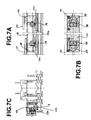
- the rocker block 19 is shown in elevation at Fig. 7A to 7C .
- a pad 27 of rectangular shape is screwed by screws 26 in the main groove of the profile 9, in the vicinity of one of its ends. It supports two axes 28 machined so as to form bearing ends at their ends and between them two toothed gears.
- One of these pinions meshes with a toothed rack gear machined in a vertical trunnion segment 29 guided in a bore of the stud 27.
- the latter thus carries two parallel pinion shafts 28 each meshing on the one hand with the rack bar 23a and on the other hand in one of the vertical axis pins 29. One of them carries the pellet 21 and the other the pellet 22.
- the pins 29 are guided in the stud 27, one on one side and the other on the other side with respect to the parallel axes 28. It is understood that the assembly described is mounted so that one of the pellets 21, 22 is in the high position when the other is in the lower position, so that pressing the upper pad, the rack bar is moved in one direction or the other to bring the other pellet up.
- displacement blocks 20 are distributed over the length of the fixed frame member 8 to actuate the movable blade 11.
- the number of these blocks will be three or four.
- the Fig. 4 to 6 , 8 , 9 and 10 show the conformation of these blocks.
- Each of them has a stud 30 ( Fig. 6 ) of rectangular shape, engaged in a predetermined position in the central groove of the inner profile 9 of the frame member 8.
- a rectangular groove 31 is milled in the lower face of the stud 30 so that the latter cap a bar segment 23a of the rack rod 23.
- Each stud 30 is equipped with a pinion shaft 32 supported transversely by bearings 33a and 33b, in a bore 30a which passes through the stud 30 from side to side, except bottom wall.
- the pinion shaft 32 carries a first bearing 33a at its end on the inside of the assembly 8 of the three sections 9, then a pinion 32a fixed on the shaft by a pin and meshing in the bar segment Rack 23a, then a bare element equipped with a guide nut 37 passing through the stud above the mounting rod 24, the groove 25 indicated above embraces the stud. Then the pinion shaft extends beyond the location of the outer flange 10 of the profile 9, which will be notched at this point for a length at least equal to the length of the stud 30.
- a second pinion 32b wedged on the shaft 32 by a pin On the outer end of the pinion shaft 32, which protrudes into the groove between the flanges 10 of the two adjacent sections 9, is mounted a second pinion 32b wedged on the shaft 32 by a pin.
- a second bearing 33b, housed in the stud 30 holds the pinion 32b cantilever so as to actuate the blade 11.
- the blade 11 itself has a cutout which engages the stud 30.
- the pinion 32b pinned at the end of the shaft 32 is located in a U-shaped cutout in plan, in the stud 30 and in a contoured cutout 34 of the 11.
- the latter is in straight flanks ( Fig. 8 ), open down. Its profile is such that it still has a protruding nipple 35 provided on its longitudinal side with a rack tooth 35a vertical. At the time of its formation, this nipple is also thinned for example by a stroke of the stamp. It is understood that once mounting done, the toothing of the stud 35 meshes with the pinion 32b.
- the mounting rod 24, visible to Fig. 3 to 6 and 8 to 10 allows exact positioning of the different sets of the locking device at the time of installation. It is a section of rectangular section whose dimensions allow it to be placed on the flat bottom of the central groove of the profile 9, at the foot of the outer wing 10 which will be indented at the right of the studs 30. It is fixed by 24a and has grooves 25 of a predetermined length and depth, in which the studs 30 are engaged themselves having corresponding profiles. We still see Fig.
- the Fig. 10 is a summary of the explanations given previously. It shows how the elements described are associated with respect to the movement blocks 20, the rack control rod 23 and the mounting rod 24. It is therefore not necessary to list their components again. Only the rocker control system 19 is omitted here.
- the angled locking system using a control rod with rack segments which actuate a set of geared-on displacement blocks in engagement with side rack segments integral with a movable locking blade can also be placed on a vertical frame member of an embrasure, for example to control and lock a pivoting panel on a horizontal axis.
- the control mechanism comprises instead of the block 19 a lever handle system 40 mounted on the inner profile 9 of one of the frame members forming the sides of the door frame.
- a support arm 41 is fixed to the inner flange of the profile 9.
- a lever arm 43 acting as a control handle.
- a rod 44 guided with play in a housing of the handle 43 passes through the parallel flanges 10 of the profile 9.
- On this rod is engaged a rack segment 45.
- a mounting stud in two parts 46a and 46b screwed one to the other. other is fixed by two screws in the bottom of the groove limited by the flanges 10 of the profile 9.
- This block maintains and guides, in perpendicular grooves and in a bore provided with two bearings, on the one hand the rack segment 45, on the other hand a rack segment 23a of the control rod 23 and finally a pinion 47 supported by said bearings of the block 46.
- This pinion 47 meshes simultaneously in the two rack segments 45 and 23a.
- the block 46 protrudes beyond the outer wing of the profile 9 as well as in the bottom of the groove to go to the wall of the profile which is behind and in which it is screwed.
- This block also encroaches on the connecting elements which connect the inner and inner profiles 9 of the assembly 8 of the frame profiles.
- the control mechanism could be limited to what has just been described. It would then be possible to lock and unlock the panel from inside the recess by actuating the handle 43 in one direction or the other in order to move the control rod 23 in one direction or the other.
- the control mechanism will be completed by a simple extension of the rod 44 through the wings 10 of the second and third profiles 9 of the assembly 8 and the mounting of an outer handle 48 pivoting on a support arm 49 similar to the arm 41.
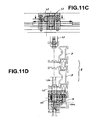
- Fig. 11B The Fig. 11C and 11D show details of execution of the block 46a-46b with the pinion 47 supported by two bearings and the control rack 45 sectional view.
- Fig. 11D the position of the control rod 23 with the rack segment 23a, housed in the bottom groove of the inner profile 9 in the vertical upright of the door frame is clearly visible. It will be understood that this control rod will have to be connected to upper and lower angle references to actuate the movable blades 11.
- the Fig. 12A and 12B show the provision of a key lock on a side element 8 of the door frame.
- the Fig. 12A causes the cross section of the inner profile 9 to appear in watermark.
- a transverse elongated structure 50 which constitutes a safety lock cylinder with a rotating movable portion 51 on which is locked a pinion 52
- the latter meshes with rack teeth 54 with teeth directed towards the bottom of the profile 9 integral with a pin 54a which acts against the edge of a lever 54b itself equipped with a pin 54c serving locking pin and engaging in the notch 54d of the slider 23c, which is integral with the vertical control rod 23.
- This system of components is housed in a housing 55. II ensures the maintenance and guidance of the moving elements linear aforementioned (rack 54, 54b lever lever and control slider 23c).
- Spacers 53 complete the lock member 50 so that it is long enough to pass through the vertical frame profile 8.
- the lock can be arranged so that the key 50a is accessible from outside the doorway or from inside.
- the provision to be provided in each case is obvious to the skilled person.
- the key 50a is outside and a wheel 50b installed inside.
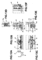
- the Fig. 13A to 13F , 14 and 15 finally show how the movements of the movable blades 11 and 11 'arranged horizontally in the high and low sides of the door frame are controlled from the mechanisms described above.
- the Fig. 13A shows in section the profile 9 forming part of the lower horizontal element of the door frame.
- the movable blade 11 placed in the groove between this profile and the neighboring section.
- She is also seen at Fig. 13B , in elevation, in a layout that corresponds exactly to that of the Fig. 3 where blocks 20 equipped with pinions 32 manipulate this blade according to the displacements of the composite control rod 23.
- Fig. 13C shows this layout in plan.
- the Fig. 13D and 13E reveal the provision of a bevel gear between the rod 23 and a vertical rod 23 'similar to that of the Fig. 11 .
- the end of the control rod 23 ' carries a cylindrical toothed segment 56 which has a short toothed rack element split into two parallel parts ( Fig. 13E ), whose teeth are directed towards the inside of the frame and mesh with the ends of the toothing of a pinion 57 supported by two bearings 58 mounted in a stud 59 ( Fig. 13D and 13F ).
- the stud 59 is fixed by screws at the end of the base profile 9 as well as at the lower end of the corresponding profile 9 'forming part of the vertical upright of the door frame.
- the rod 23 directly acting on the blade 11 acts as a secondary control rod. A displacement of this control rod 23 to the right at the Fig.
- 13D is caused by the rack segment 23c by a rotation of the pinion 57 in the direction of the arrow 60, which results from an upward movement of a vertical control rod assembly 23 housed in the profile 9 'by the intermediate of the cylindrical toothed segment 56.
- the connection between the sections 9 and 9 ' is made by riveting.
- a reinforcing bracket 61 fixed by screws ensures the rigidity of the assembly.
Landscapes
- Engineering & Computer Science (AREA)
- Mechanical Engineering (AREA)
- Specific Sealing Or Ventilating Devices For Doors And Windows (AREA)
- Orthopedics, Nursing, And Contraception (AREA)
Priority Applications (3)
| Application Number | Priority Date | Filing Date | Title |
|---|---|---|---|
| ES08101898.8T ES2541313T3 (es) | 2008-02-22 | 2008-02-22 | Dispositivo de enclavamiento estanco de un panel montado de manera pivotante sobre un eje, en un hueco |
| PT81018988T PT2093359E (pt) | 2008-02-22 | 2008-02-22 | Dispositivo para o fecho estanque de um painel montado de modo a rodar em torno de um eixo, numa abertura |
| EP20080101898 EP2093359B1 (fr) | 2008-02-22 | 2008-02-22 | Dispositif de verrouillage étanche d'un panneau monté à pivotement sur un axe, dans une embrasure |
Applications Claiming Priority (1)
| Application Number | Priority Date | Filing Date | Title |
|---|---|---|---|
| EP20080101898 EP2093359B1 (fr) | 2008-02-22 | 2008-02-22 | Dispositif de verrouillage étanche d'un panneau monté à pivotement sur un axe, dans une embrasure |
Publications (2)
| Publication Number | Publication Date |
|---|---|
| EP2093359A1 EP2093359A1 (fr) | 2009-08-26 |
| EP2093359B1 true EP2093359B1 (fr) | 2015-04-08 |
Family
ID=39760731
Family Applications (1)
| Application Number | Title | Priority Date | Filing Date |
|---|---|---|---|
| EP20080101898 Not-in-force EP2093359B1 (fr) | 2008-02-22 | 2008-02-22 | Dispositif de verrouillage étanche d'un panneau monté à pivotement sur un axe, dans une embrasure |
Country Status (3)
| Country | Link |
|---|---|
| EP (1) | EP2093359B1 (es) |
| ES (1) | ES2541313T3 (es) |
| PT (1) | PT2093359E (es) |
Family Cites Families (6)
| Publication number | Priority date | Publication date | Assignee | Title |
|---|---|---|---|---|
| US1471525A (en) * | 1921-09-20 | 1923-10-23 | Pavola Alfred | Window lock and guard |
| GB996005A (en) * | 1961-01-24 | 1965-06-23 | Nat Res Dev | Improvements in or relating to bolt actuating mechanisms |
| US4307542A (en) * | 1979-10-09 | 1981-12-29 | Amerock Corporation | Window |
| DE19846317C2 (de) * | 1998-03-25 | 2002-10-24 | Siegenia Frank Kg | Beschlag für Fenster oder Türen |
| EP1426529A1 (en) * | 2002-11-19 | 2004-06-09 | Rosengrens Benelux B.V. | Lock |
| US7707773B2 (en) * | 2005-12-30 | 2010-05-04 | Speyer Door And Window, Inc. | Seal activation system positioned within panel for door/window |
-
2008
- 2008-02-22 ES ES08101898.8T patent/ES2541313T3/es active Active
- 2008-02-22 EP EP20080101898 patent/EP2093359B1/fr not_active Not-in-force
- 2008-02-22 PT PT81018988T patent/PT2093359E/pt unknown
Also Published As
| Publication number | Publication date |
|---|---|
| PT2093359E (pt) | 2015-08-24 |
| ES2541313T3 (es) | 2015-07-17 |
| EP2093359A1 (fr) | 2009-08-26 |
Similar Documents
| Publication | Publication Date | Title |
|---|---|---|
| EP2112302B1 (fr) | Dispositif de verrouillage de porte à crémone | |
| EP2260167B1 (fr) | Vitrage pourvu d'un châssis, monté à pivotement autour d'un axe dans un cadre d'embrasure fixe | |
| FR2580028A1 (es) | ||
| EP2093359B1 (fr) | Dispositif de verrouillage étanche d'un panneau monté à pivotement sur un axe, dans une embrasure | |
| FR2722527A1 (fr) | Dispositif de verrouillage pour chassis a frappe | |
| EP2554768A1 (fr) | Dispositif de verrouillage/déverrouillage pour ouvrant à poignée escamotable | |
| EP2394910B1 (fr) | Fenêtre ouvrante d'aéronef et aéronef équipé d'au moins une telle fenêtre | |
| EP2401443A1 (fr) | Caisson lumineux a ouverture roto-translative | |
| FR3035672A1 (fr) | Menuiserie a commande de verrouillage sur le dormant | |
| EP0715048B1 (fr) | Ferrure de verrouillage pour porte, fenêtre ou analogue | |
| FR2861789A1 (fr) | Serrure anti-panique multipoint reversible | |
| FR3080881A1 (fr) | Systeme de fermeture a verrouillage mecanique | |
| LU87614A1 (fr) | Dispositif de verrouillage de fenetre | |
| EP0698709B1 (fr) | Crémone ou crémone-serrure | |
| FR2583452A1 (fr) | Boitier de cremone a plaquer avec condamnation. | |
| FR2591270A1 (fr) | Porte coupe-feu a double battant | |
| FR2581692A1 (fr) | Serrure pour fermeture et notamment de porte a barre de poussee | |
| FR2681369A1 (fr) | Dispositif de surete pour portes, fenetres et analogues. | |
| EP2357303B1 (fr) | Dispositif de verrouillage à plusieurs points de condamnation | |
| WO2023099540A1 (fr) | Systeme d'ouverture d'une porte configuree pour s'ouvrir a gauche ou a droite, vers l'exterieur et vers l'interieur | |
| EP0345186A1 (fr) | Compas entrebailleur pour fenêtre s'ouvrant à l'italienne, à l'australienne, pivotante ou à ouvertures analogues | |
| FR2705396A1 (fr) | Porte, en particulier porte anti-souffle. | |
| EP1004732A1 (fr) | Mécanisme de commande pour crémone | |
| FR2793278A1 (fr) | Portail automatique a vantail rotatif | |
| EP1369549A1 (fr) | Vantail autoporteur pour porte basculante |
Legal Events
| Date | Code | Title | Description |
|---|---|---|---|
| PUAI | Public reference made under article 153(3) epc to a published international application that has entered the european phase |
Free format text: ORIGINAL CODE: 0009012 |
|
| AK | Designated contracting states |
Kind code of ref document: A1 Designated state(s): AT BE BG CH CY CZ DE DK EE ES FI FR GB GR HR HU IE IS IT LI LT LU LV MC MT NL NO PL PT RO SE SI SK TR |
|
| AX | Request for extension of the european patent |
Extension state: AL BA MK |
|
| 17P | Request for examination filed |
Effective date: 20100225 |
|
| 17Q | First examination report despatched |
Effective date: 20100331 |
|
| AKX | Designation fees paid |
Designated state(s): AT BE BG CH CY CZ DE DK EE ES FI FR GB GR HR HU IE IS IT LI LT LU LV MC MT NL NO PL PT RO SE SI SK TR |
|
| RAP1 | Party data changed (applicant data changed or rights of an application transferred) |
Owner name: ORCHIDEES CONSTRUCTIONS S.A. |
|
| RAP1 | Party data changed (applicant data changed or rights of an application transferred) |
Owner name: ORCHIDEES CONSTRUCTIONS S.A. |
|
| GRAP | Despatch of communication of intention to grant a patent |
Free format text: ORIGINAL CODE: EPIDOSNIGR1 |
|
| INTG | Intention to grant announced |
Effective date: 20141114 |
|
| GRAS | Grant fee paid |
Free format text: ORIGINAL CODE: EPIDOSNIGR3 |
|
| GRAA | (expected) grant |
Free format text: ORIGINAL CODE: 0009210 |
|
| AK | Designated contracting states |
Kind code of ref document: B1 Designated state(s): AT BE BG CH CY CZ DE DK EE ES FI FR GB GR HR HU IE IS IT LI LT LU LV MC MT NL NO PL PT RO SE SI SK TR |
|
| REG | Reference to a national code |
Ref country code: GB Ref legal event code: FG4D Free format text: NOT ENGLISH |
|
| REG | Reference to a national code |
Ref country code: CH Ref legal event code: EP |
|
| REG | Reference to a national code |
Ref country code: IE Ref legal event code: FG4D Free format text: LANGUAGE OF EP DOCUMENT: FRENCH |
|
| REG | Reference to a national code |
Ref country code: AT Ref legal event code: REF Ref document number: 720715 Country of ref document: AT Kind code of ref document: T Effective date: 20150515 |
|
| REG | Reference to a national code |
Ref country code: DE Ref legal event code: R096 Ref document number: 602008037507 Country of ref document: DE Effective date: 20150521 |
|
| REG | Reference to a national code |
Ref country code: CH Ref legal event code: NV Representative=s name: ABREMA AGENCE BREVET ET MARQUES, GANGUILLET, CH |
|
| REG | Reference to a national code |
Ref country code: NL Ref legal event code: T3 |
|
| REG | Reference to a national code |
Ref country code: ES Ref legal event code: FG2A Ref document number: 2541313 Country of ref document: ES Kind code of ref document: T3 Effective date: 20150717 |
|
| REG | Reference to a national code |
Ref country code: PT Ref legal event code: SC4A Free format text: AVAILABILITY OF NATIONAL TRANSLATION Effective date: 20150702 |
|
| REG | Reference to a national code |
Ref country code: LT Ref legal event code: MG4D |
|
| PG25 | Lapsed in a contracting state [announced via postgrant information from national office to epo] |
Ref country code: LT Free format text: LAPSE BECAUSE OF FAILURE TO SUBMIT A TRANSLATION OF THE DESCRIPTION OR TO PAY THE FEE WITHIN THE PRESCRIBED TIME-LIMIT Effective date: 20150408 Ref country code: HR Free format text: LAPSE BECAUSE OF FAILURE TO SUBMIT A TRANSLATION OF THE DESCRIPTION OR TO PAY THE FEE WITHIN THE PRESCRIBED TIME-LIMIT Effective date: 20150408 Ref country code: NO Free format text: LAPSE BECAUSE OF FAILURE TO SUBMIT A TRANSLATION OF THE DESCRIPTION OR TO PAY THE FEE WITHIN THE PRESCRIBED TIME-LIMIT Effective date: 20150708 Ref country code: FI Free format text: LAPSE BECAUSE OF FAILURE TO SUBMIT A TRANSLATION OF THE DESCRIPTION OR TO PAY THE FEE WITHIN THE PRESCRIBED TIME-LIMIT Effective date: 20150408 |
|
| PG25 | Lapsed in a contracting state [announced via postgrant information from national office to epo] |
Ref country code: IS Free format text: LAPSE BECAUSE OF FAILURE TO SUBMIT A TRANSLATION OF THE DESCRIPTION OR TO PAY THE FEE WITHIN THE PRESCRIBED TIME-LIMIT Effective date: 20150808 Ref country code: GR Free format text: LAPSE BECAUSE OF FAILURE TO SUBMIT A TRANSLATION OF THE DESCRIPTION OR TO PAY THE FEE WITHIN THE PRESCRIBED TIME-LIMIT Effective date: 20150709 Ref country code: LV Free format text: LAPSE BECAUSE OF FAILURE TO SUBMIT A TRANSLATION OF THE DESCRIPTION OR TO PAY THE FEE WITHIN THE PRESCRIBED TIME-LIMIT Effective date: 20150408 |
|
| REG | Reference to a national code |
Ref country code: DE Ref legal event code: R097 Ref document number: 602008037507 Country of ref document: DE |
|
| PG25 | Lapsed in a contracting state [announced via postgrant information from national office to epo] |
Ref country code: EE Free format text: LAPSE BECAUSE OF FAILURE TO SUBMIT A TRANSLATION OF THE DESCRIPTION OR TO PAY THE FEE WITHIN THE PRESCRIBED TIME-LIMIT Effective date: 20150408 Ref country code: DK Free format text: LAPSE BECAUSE OF FAILURE TO SUBMIT A TRANSLATION OF THE DESCRIPTION OR TO PAY THE FEE WITHIN THE PRESCRIBED TIME-LIMIT Effective date: 20150408 |
|
| PLBE | No opposition filed within time limit |
Free format text: ORIGINAL CODE: 0009261 |
|
| STAA | Information on the status of an ep patent application or granted ep patent |
Free format text: STATUS: NO OPPOSITION FILED WITHIN TIME LIMIT |
|
| REG | Reference to a national code |
Ref country code: FR Ref legal event code: PLFP Year of fee payment: 9 |
|
| PG25 | Lapsed in a contracting state [announced via postgrant information from national office to epo] |
Ref country code: RO Free format text: LAPSE BECAUSE OF NON-PAYMENT OF DUE FEES Effective date: 20150408 Ref country code: SK Free format text: LAPSE BECAUSE OF FAILURE TO SUBMIT A TRANSLATION OF THE DESCRIPTION OR TO PAY THE FEE WITHIN THE PRESCRIBED TIME-LIMIT Effective date: 20150408 Ref country code: CZ Free format text: LAPSE BECAUSE OF FAILURE TO SUBMIT A TRANSLATION OF THE DESCRIPTION OR TO PAY THE FEE WITHIN THE PRESCRIBED TIME-LIMIT Effective date: 20150408 Ref country code: PL Free format text: LAPSE BECAUSE OF FAILURE TO SUBMIT A TRANSLATION OF THE DESCRIPTION OR TO PAY THE FEE WITHIN THE PRESCRIBED TIME-LIMIT Effective date: 20150408 |
|
| 26N | No opposition filed |
Effective date: 20160111 |
|
| PG25 | Lapsed in a contracting state [announced via postgrant information from national office to epo] |
Ref country code: IT Free format text: LAPSE BECAUSE OF FAILURE TO SUBMIT A TRANSLATION OF THE DESCRIPTION OR TO PAY THE FEE WITHIN THE PRESCRIBED TIME-LIMIT Effective date: 20150408 |
|
| PGFP | Annual fee paid to national office [announced via postgrant information from national office to epo] |
Ref country code: CH Payment date: 20160307 Year of fee payment: 9 Ref country code: DE Payment date: 20160218 Year of fee payment: 9 Ref country code: ES Payment date: 20160210 Year of fee payment: 9 |
|
| PG25 | Lapsed in a contracting state [announced via postgrant information from national office to epo] |
Ref country code: SI Free format text: LAPSE BECAUSE OF FAILURE TO SUBMIT A TRANSLATION OF THE DESCRIPTION OR TO PAY THE FEE WITHIN THE PRESCRIBED TIME-LIMIT Effective date: 20150408 |
|
| PGFP | Annual fee paid to national office [announced via postgrant information from national office to epo] |
Ref country code: AT Payment date: 20160218 Year of fee payment: 9 Ref country code: NL Payment date: 20160217 Year of fee payment: 9 Ref country code: GB Payment date: 20160217 Year of fee payment: 9 Ref country code: PT Payment date: 20160219 Year of fee payment: 9 Ref country code: BE Payment date: 20160217 Year of fee payment: 9 Ref country code: FR Payment date: 20160218 Year of fee payment: 9 |
|
| PG25 | Lapsed in a contracting state [announced via postgrant information from national office to epo] |
Ref country code: LU Free format text: LAPSE BECAUSE OF FAILURE TO SUBMIT A TRANSLATION OF THE DESCRIPTION OR TO PAY THE FEE WITHIN THE PRESCRIBED TIME-LIMIT Effective date: 20160222 Ref country code: MC Free format text: LAPSE BECAUSE OF FAILURE TO SUBMIT A TRANSLATION OF THE DESCRIPTION OR TO PAY THE FEE WITHIN THE PRESCRIBED TIME-LIMIT Effective date: 20150408 |
|
| REG | Reference to a national code |
Ref country code: IE Ref legal event code: MM4A |
|
| PG25 | Lapsed in a contracting state [announced via postgrant information from national office to epo] |
Ref country code: IE Free format text: LAPSE BECAUSE OF NON-PAYMENT OF DUE FEES Effective date: 20160222 |
|
| REG | Reference to a national code |
Ref country code: AT Ref legal event code: UEP Ref document number: 720715 Country of ref document: AT Kind code of ref document: T Effective date: 20150408 |
|
| PG25 | Lapsed in a contracting state [announced via postgrant information from national office to epo] |
Ref country code: BE Free format text: LAPSE BECAUSE OF NON-PAYMENT OF DUE FEES Effective date: 20170228 |
|
| PG25 | Lapsed in a contracting state [announced via postgrant information from national office to epo] |
Ref country code: SE Free format text: LAPSE BECAUSE OF FAILURE TO SUBMIT A TRANSLATION OF THE DESCRIPTION OR TO PAY THE FEE WITHIN THE PRESCRIBED TIME-LIMIT Effective date: 20150408 |
|
| PG25 | Lapsed in a contracting state [announced via postgrant information from national office to epo] |
Ref country code: MT Free format text: LAPSE BECAUSE OF FAILURE TO SUBMIT A TRANSLATION OF THE DESCRIPTION OR TO PAY THE FEE WITHIN THE PRESCRIBED TIME-LIMIT Effective date: 20150408 |
|
| REG | Reference to a national code |
Ref country code: DE Ref legal event code: R119 Ref document number: 602008037507 Country of ref document: DE |
|
| REG | Reference to a national code |
Ref country code: CH Ref legal event code: PL |
|
| REG | Reference to a national code |
Ref country code: NL Ref legal event code: MM Effective date: 20170301 |
|
| REG | Reference to a national code |
Ref country code: AT Ref legal event code: MM01 Ref document number: 720715 Country of ref document: AT Kind code of ref document: T Effective date: 20170222 |
|
| GBPC | Gb: european patent ceased through non-payment of renewal fee |
Effective date: 20170222 |
|
| PG25 | Lapsed in a contracting state [announced via postgrant information from national office to epo] |
Ref country code: AT Free format text: LAPSE BECAUSE OF NON-PAYMENT OF DUE FEES Effective date: 20170222 Ref country code: CH Free format text: LAPSE BECAUSE OF NON-PAYMENT OF DUE FEES Effective date: 20170228 Ref country code: LI Free format text: LAPSE BECAUSE OF NON-PAYMENT OF DUE FEES Effective date: 20170228 |
|
| PG25 | Lapsed in a contracting state [announced via postgrant information from national office to epo] |
Ref country code: NL Free format text: LAPSE BECAUSE OF NON-PAYMENT OF DUE FEES Effective date: 20170301 Ref country code: PT Free format text: LAPSE BECAUSE OF NON-PAYMENT OF DUE FEES Effective date: 20170822 |
|
| REG | Reference to a national code |
Ref country code: FR Ref legal event code: ST Effective date: 20171031 |
|
| PG25 | Lapsed in a contracting state [announced via postgrant information from national office to epo] |
Ref country code: FR Free format text: LAPSE BECAUSE OF NON-PAYMENT OF DUE FEES Effective date: 20170228 Ref country code: DE Free format text: LAPSE BECAUSE OF NON-PAYMENT OF DUE FEES Effective date: 20170901 |
|
| REG | Reference to a national code |
Ref country code: BE Ref legal event code: MM Effective date: 20170228 |
|
| PG25 | Lapsed in a contracting state [announced via postgrant information from national office to epo] |
Ref country code: GB Free format text: LAPSE BECAUSE OF NON-PAYMENT OF DUE FEES Effective date: 20170222 |
|
| PG25 | Lapsed in a contracting state [announced via postgrant information from national office to epo] |
Ref country code: CY Free format text: LAPSE BECAUSE OF FAILURE TO SUBMIT A TRANSLATION OF THE DESCRIPTION OR TO PAY THE FEE WITHIN THE PRESCRIBED TIME-LIMIT Effective date: 20150408 Ref country code: HU Free format text: LAPSE BECAUSE OF FAILURE TO SUBMIT A TRANSLATION OF THE DESCRIPTION OR TO PAY THE FEE WITHIN THE PRESCRIBED TIME-LIMIT; INVALID AB INITIO Effective date: 20080222 |
|
| PG25 | Lapsed in a contracting state [announced via postgrant information from national office to epo] |
Ref country code: TR Free format text: LAPSE BECAUSE OF FAILURE TO SUBMIT A TRANSLATION OF THE DESCRIPTION OR TO PAY THE FEE WITHIN THE PRESCRIBED TIME-LIMIT Effective date: 20150408 |
|
| REG | Reference to a national code |
Ref country code: ES Ref legal event code: FD2A Effective date: 20180710 |
|
| PG25 | Lapsed in a contracting state [announced via postgrant information from national office to epo] |
Ref country code: BG Free format text: LAPSE BECAUSE OF FAILURE TO SUBMIT A TRANSLATION OF THE DESCRIPTION OR TO PAY THE FEE WITHIN THE PRESCRIBED TIME-LIMIT Effective date: 20150408 |
|
| PG25 | Lapsed in a contracting state [announced via postgrant information from national office to epo] |
Ref country code: ES Free format text: LAPSE BECAUSE OF NON-PAYMENT OF DUE FEES Effective date: 20170223 |