EP2093301A1 - Superhard tip and process for producing the same - Google Patents
Superhard tip and process for producing the same Download PDFInfo
- Publication number
- EP2093301A1 EP2093301A1 EP06832974A EP06832974A EP2093301A1 EP 2093301 A1 EP2093301 A1 EP 2093301A1 EP 06832974 A EP06832974 A EP 06832974A EP 06832974 A EP06832974 A EP 06832974A EP 2093301 A1 EP2093301 A1 EP 2093301A1
- Authority
- EP
- European Patent Office
- Prior art keywords
- bonding
- bonding metal
- nose
- tip
- layer
- Prior art date
- Legal status (The legal status is an assumption and is not a legal conclusion. Google has not performed a legal analysis and makes no representation as to the accuracy of the status listed.)
- Granted
Links
- 238000000034 method Methods 0.000 title claims description 26
- 229910052751 metal Inorganic materials 0.000 claims abstract description 77
- 239000002184 metal Substances 0.000 claims abstract description 77
- 238000005245 sintering Methods 0.000 claims abstract description 47
- 239000000956 alloy Substances 0.000 claims abstract description 41
- 229910045601 alloy Inorganic materials 0.000 claims abstract description 41
- 239000000126 substance Substances 0.000 claims abstract description 36
- 230000005496 eutectics Effects 0.000 claims abstract description 33
- 239000000203 mixture Substances 0.000 claims abstract description 32
- 230000008018 melting Effects 0.000 claims abstract description 18
- 238000002844 melting Methods 0.000 claims abstract description 18
- 238000013329 compounding Methods 0.000 claims abstract description 17
- 239000007791 liquid phase Substances 0.000 claims abstract description 12
- 239000000843 powder Substances 0.000 claims description 66
- 238000010438 heat treatment Methods 0.000 claims description 17
- 238000004519 manufacturing process Methods 0.000 claims description 12
- 238000005520 cutting process Methods 0.000 description 99
- 239000010410 layer Substances 0.000 description 78
- PXHVJJICTQNCMI-UHFFFAOYSA-N nickel Substances [Ni] PXHVJJICTQNCMI-UHFFFAOYSA-N 0.000 description 54
- 229910052759 nickel Inorganic materials 0.000 description 25
- 239000011812 mixed powder Substances 0.000 description 22
- 229910017052 cobalt Inorganic materials 0.000 description 21
- 239000010941 cobalt Substances 0.000 description 21
- GUTLYIVDDKVIGB-UHFFFAOYSA-N cobalt atom Chemical compound [Co] GUTLYIVDDKVIGB-UHFFFAOYSA-N 0.000 description 21
- 239000000463 material Substances 0.000 description 20
- 239000002245 particle Substances 0.000 description 18
- 239000011651 chromium Substances 0.000 description 9
- 238000009826 distribution Methods 0.000 description 9
- 238000003754 machining Methods 0.000 description 9
- UONOETXJSWQNOL-UHFFFAOYSA-N tungsten carbide Chemical compound [W+]#[C-] UONOETXJSWQNOL-UHFFFAOYSA-N 0.000 description 9
- 238000003466 welding Methods 0.000 description 8
- VYZAMTAEIAYCRO-UHFFFAOYSA-N Chromium Chemical compound [Cr] VYZAMTAEIAYCRO-UHFFFAOYSA-N 0.000 description 6
- 229910052804 chromium Inorganic materials 0.000 description 6
- 239000013528 metallic particle Substances 0.000 description 6
- IJGRMHOSHXDMSA-UHFFFAOYSA-N Atomic nitrogen Chemical compound N#N IJGRMHOSHXDMSA-UHFFFAOYSA-N 0.000 description 5
- 229910001873 dinitrogen Inorganic materials 0.000 description 5
- 238000005219 brazing Methods 0.000 description 4
- 238000005553 drilling Methods 0.000 description 4
- 230000003647 oxidation Effects 0.000 description 4
- 238000007254 oxidation reaction Methods 0.000 description 4
- 241000196324 Embryophyta Species 0.000 description 3
- 229910000831 Steel Inorganic materials 0.000 description 3
- 238000010278 pulse charging Methods 0.000 description 3
- 239000010959 steel Substances 0.000 description 3
- VNTLIPZTSJSULJ-UHFFFAOYSA-N chromium molybdenum Chemical compound [Cr].[Mo] VNTLIPZTSJSULJ-UHFFFAOYSA-N 0.000 description 2
- 230000000694 effects Effects 0.000 description 2
- 230000004927 fusion Effects 0.000 description 2
- 150000002739 metals Chemical class 0.000 description 2
- 239000011435 rock Substances 0.000 description 2
- 229910000975 Carbon steel Inorganic materials 0.000 description 1
- 229910020630 Co Ni Inorganic materials 0.000 description 1
- 229910009043 WC-Co Inorganic materials 0.000 description 1
- 239000011230 binding agent Substances 0.000 description 1
- 239000010962 carbon steel Substances 0.000 description 1
- 239000004615 ingredient Substances 0.000 description 1
- 238000010587 phase diagram Methods 0.000 description 1
- 230000000630 rising effect Effects 0.000 description 1
- 239000002356 single layer Substances 0.000 description 1
- 239000007787 solid Substances 0.000 description 1
- 239000004575 stone Substances 0.000 description 1
Images


Classifications
-
- B—PERFORMING OPERATIONS; TRANSPORTING
- B22—CASTING; POWDER METALLURGY
- B22F—WORKING METALLIC POWDER; MANUFACTURE OF ARTICLES FROM METALLIC POWDER; MAKING METALLIC POWDER; APPARATUS OR DEVICES SPECIALLY ADAPTED FOR METALLIC POWDER
- B22F7/00—Manufacture of composite layers, workpieces, or articles, comprising metallic powder, by sintering the powder, with or without compacting wherein at least one part is obtained by sintering or compression
- B22F7/02—Manufacture of composite layers, workpieces, or articles, comprising metallic powder, by sintering the powder, with or without compacting wherein at least one part is obtained by sintering or compression of composite layers
-
- C—CHEMISTRY; METALLURGY
- C22—METALLURGY; FERROUS OR NON-FERROUS ALLOYS; TREATMENT OF ALLOYS OR NON-FERROUS METALS
- C22C—ALLOYS
- C22C29/00—Alloys based on carbides, oxides, nitrides, borides, or silicides, e.g. cermets, or other metal compounds, e.g. oxynitrides, sulfides
- C22C29/02—Alloys based on carbides, oxides, nitrides, borides, or silicides, e.g. cermets, or other metal compounds, e.g. oxynitrides, sulfides based on carbides or carbonitrides
- C22C29/06—Alloys based on carbides, oxides, nitrides, borides, or silicides, e.g. cermets, or other metal compounds, e.g. oxynitrides, sulfides based on carbides or carbonitrides based on carbides, but not containing other metal compounds
- C22C29/08—Alloys based on carbides, oxides, nitrides, borides, or silicides, e.g. cermets, or other metal compounds, e.g. oxynitrides, sulfides based on carbides or carbonitrides based on carbides, but not containing other metal compounds based on tungsten carbide
-
- B—PERFORMING OPERATIONS; TRANSPORTING
- B22—CASTING; POWDER METALLURGY
- B22F—WORKING METALLIC POWDER; MANUFACTURE OF ARTICLES FROM METALLIC POWDER; MAKING METALLIC POWDER; APPARATUS OR DEVICES SPECIALLY ADAPTED FOR METALLIC POWDER
- B22F7/00—Manufacture of composite layers, workpieces, or articles, comprising metallic powder, by sintering the powder, with or without compacting wherein at least one part is obtained by sintering or compression
- B22F7/06—Manufacture of composite layers, workpieces, or articles, comprising metallic powder, by sintering the powder, with or without compacting wherein at least one part is obtained by sintering or compression of composite workpieces or articles from parts, e.g. to form tipped tools
- B22F7/062—Manufacture of composite layers, workpieces, or articles, comprising metallic powder, by sintering the powder, with or without compacting wherein at least one part is obtained by sintering or compression of composite workpieces or articles from parts, e.g. to form tipped tools involving the connection or repairing of preformed parts
- B22F7/064—Manufacture of composite layers, workpieces, or articles, comprising metallic powder, by sintering the powder, with or without compacting wherein at least one part is obtained by sintering or compression of composite workpieces or articles from parts, e.g. to form tipped tools involving the connection or repairing of preformed parts using an intermediate powder layer
-
- B—PERFORMING OPERATIONS; TRANSPORTING
- B22—CASTING; POWDER METALLURGY
- B22F—WORKING METALLIC POWDER; MANUFACTURE OF ARTICLES FROM METALLIC POWDER; MAKING METALLIC POWDER; APPARATUS OR DEVICES SPECIALLY ADAPTED FOR METALLIC POWDER
- B22F5/00—Manufacture of workpieces or articles from metallic powder characterised by the special shape of the product
- B22F2005/001—Cutting tools, earth boring or grinding tool other than table ware
-
- B—PERFORMING OPERATIONS; TRANSPORTING
- B22—CASTING; POWDER METALLURGY
- B22F—WORKING METALLIC POWDER; MANUFACTURE OF ARTICLES FROM METALLIC POWDER; MAKING METALLIC POWDER; APPARATUS OR DEVICES SPECIALLY ADAPTED FOR METALLIC POWDER
- B22F2999/00—Aspects linked to processes or compositions used in powder metallurgy
-
- Y—GENERAL TAGGING OF NEW TECHNOLOGICAL DEVELOPMENTS; GENERAL TAGGING OF CROSS-SECTIONAL TECHNOLOGIES SPANNING OVER SEVERAL SECTIONS OF THE IPC; TECHNICAL SUBJECTS COVERED BY FORMER USPC CROSS-REFERENCE ART COLLECTIONS [XRACs] AND DIGESTS
- Y10—TECHNICAL SUBJECTS COVERED BY FORMER USPC
- Y10T—TECHNICAL SUBJECTS COVERED BY FORMER US CLASSIFICATION
- Y10T408/00—Cutting by use of rotating axially moving tool
- Y10T408/78—Tool of specific diverse material
Abstract
Description
- The present invention relates to a hard tip suitable for a cutting edge tip made of sintered hard alloy bonded to the end of the main part of a drill bit by brazing, welding or the like, and the material of the noze of various machining tools and cutting tools such as a tip saw, an weed cutting machine, a saw or the like.
- For example, in order to drill a hole in concrete and stone or the like, it is generally conducted to attach an exclusive drill bit to a rotating hammer drill and simultaneously give a vibratory impact along the axial direction and a rotating torque to the drill bit. In order to satisfy the demand for high efficiency of the drilling work, the steelmade drill bit , to the end of which a good wear-resistant cutting edge tip made of sintered hard alloy was fixed by brazing, welding or the like, is employed for the drill bit. For example, Japanese patent laid-open application publication No.
Hei 7-180463 - Well, the cutting edge tip of the drill bit employs the following constitution to carry out the machining function. A hard metal made of metallic carbide, which has a relatively higher hardness and strength with wear resistance, is mainly employed for the material of the nose. A bonding metal such as cobalt or the like which has a relatively lower hardness with toughness, is mainly employed for the material of the bonding side which bonds the cutting edge tip to the main part of the drill bit. That is, the material of the nose side of the cutting edge tip is needed to have wear resistance, and the material of the bonding side of the cutting edge tip is needed to contain much material which is easily bonded to the other material and have a near coefficient of thermal expansion to that of the other material. Thus, the different properties are necessary for the nose side and the bonding side of the cutting edge tip to be bonded to the end of the drill bit.
- As one of prior arts,
patent reference 1 discloses the following drill bit: The drill bit consists of a bit head which forms a contact surface with rock surface or rocky mountain and a stem portion which is an attachment part to a device. The bit head consists of a head tip portion and a fitting portion which is integrally fusion-welded with the base of the head tip portion and fitted to the stem portion. The head tip portion is harder than the fitting portion and the hardness of the head tip portion made of sintered hard alloy is gardient so that the hardness of the end is higher than the base. -
Patent reference 2 discloses the following drill bit: The drill bit consists of a head tip portion which plays a leading role in the drilling work to rock surface or rocky mountain and a shank portion which is an attachment part to a device. The head tip portion is integrally fusion-welded with the shank portion. The hardness of the head tip portion made of sintered hard alloy is gardient so that the hardness of the end is higher than the base adjacent to the shank portion. -
Patent reference 3 discloses a method for producing a sintered body having a gradient chemical composition by pulse charging sintering. -
Patent references
Patent reference 1: Japanes Patent laid-open application publication No.Hei 8-100589
Patent reference 2: Japanese Patent laid-open application publication No.Hei 8-170482
Patent reference 3: Japanese Patent laid-open application publication No.2006-118033
Patent reference 4:Japanese Patent publication No.Hei 10-511740
Patent reference 5: Japanese Patent laid-open application publication No.Sho 61-231104 - But, inventions set forth in the
patent references 1 to 5 have the following disadvantages. - The method for producing the drill bit by an electrical discharge plasma sintering process is described in the
patent reference 1. As shown infigure 23(a) , WC -Co powder 22 containing cobalt by ten percent of weight is filled into asintering die 21 of an electrical discharge plasma sintering machine having a forming surface corresponding to the shape of the head tip portion by necessary quantity. Next, as shown infigure 23(b) , WC -Co powder 23 containing cobalt by twenty five percent of weight is placed on thepowder 22 by necessary quantity. Furthermore, as shown infigure 23(c) , anend flange 25 of afitting material 24 cut off from carbon steel bar is brought into contact with the upper surface of thepowder 23, pressure is added to thefitting material 24 from above and thesintering die 21 is put in between the electrodes of the electrical discharge plasma sintering machine to add pulse voltage. By this electrical discharge plasma sintering process, the electrical discharge plasma with extremely high temperature is generated at mutual contact points of powder particles when pulse voltage is added, powder is instantaneously heated by the electrical discharge, and the powder particles are sintered one another by fusion welding. Passages 0012 and 0013 of thepatent reference 2 also state that the drill bit is produced by the electrical discharge plasma sintering process. The electrical discharge plasma sintering process set forth in thepatent references - A short time heating (rapid rising in temperature) is conducted in the pulse charging sintering disclosed in
patent reference 3. In this case, the same sintering temperature cannot be obtained at the plane perpendicular to the pulse charging direction and the temperature of the outer circumference is lower than the center. As a result, the outer circumference is not sufficiently sintered or the center is excessively sintered and the ingredients are fused out. - Furthermore, as the diameter of metallic particles becomes finer, the hardness tends to rise. On the other hand, as the diameter of metallic particles becomes coarser, the hardness tends to lower. As the content of the bonding metal becomes larger, the hardness tends to lower. On the other hand, as the content of the bonding metal becomes smaller, the hardness tends to rise. In this point, in the metallic product according to
patent references - When a cutting edge tip made of sintered hard alloy is bonded to a drill bit made of special steel by brazing or welding, a complex residual stress is created at the bonding point of the cutting edge tip and the main part of the drill bit because of the difference of coefficient of thermal expansion between the cutting edge tip and the mian part of the drill bit having different chemical components each other. For this reason, when the bonding side of the cutting edge tip is not provided with toughness, the cutting edge tip is liable to be damaged. Even if the damage is not done at the time of the bonding, there is a possibility of the cutting edge tip coming off the drill bit in the actual drilling work when the bonding side of the cutting edge tip is not provided with toughness. The reason is because the complex residual stress is created at the bonding point of the cutting edge tip and the main part of the drill bit due to the difference of coefficient of thermal expansion between the cutting edge tip and the main part of the drill bit having different chemical components each other.
- The foregoing is stated in the case that the hard tip of the present invention was applied to the cutting edge tip at the end of the drill bit. There is a common demand for the material of the noze of various machining tools and cutting tools such as a tip saw, an weed cutting machine, a saw or the like as well as a drill bit. That is, the ens of the material of the nose is requested to provide with wear resistance and the bonding side for bonding the nose to the main part is requested to include a lot of the material which is easily bonded to the main part and have a near coefficient of thermal expansion to that of the main part. Thus, it is requested to mass-produce industrially a hard tip where the nose side and the bonding side have the different properties respectively.
- In view of the foregoing, the object of the invention is to provide a hard tip where the nose side have wear resistance and the bonding side have toughness, and a method for producing simply and inexpensively the hard tip where the hard tip of the nose side is not damaged or does not come off when the hard tip is bonded to the main part of machining tools and cutting tools and those tools are in use.
- The present inventor has done the earnest research in order to achieve the above object. As a result, the present inventor has attained to perfection of the invention wherein a hard tip of gradient chemical composition, in which the nose side have wear resistance and the bonding side have toughness, can be simply produced, as described below.
- That is, a vacuum sintering (sintering under a lower pressure than atmospheric pressure (1013 hectopascals)) which is relatively inexpensive is suitable for mass production. But, it is needed to maintain a sintering temperature (approximately 1350 to 1450 °C) for 30 to 60 minutes. Accordingly, long time is necessary for completion of the vacuum sintering. Therefore, when the hard tip of gradient chemical composition, in which the nose side have good wear resistance and the bonding side have good toughness, is produced by the vacuum sintering, the elements constituting the gradient chemical composition diffuse one another during long time sintering process and the chemical composition is homogenized. So, it is not possible to maintain the gradient chemical composition.
- Well, as shown in
figure 22 , WC - Co (tungsten carbide) sintered hard alloy forms the eutectic texture and the liquid phase sintering of WC - Co sintered hard alloy can be done at a temperature of melting point (1490 °C) or less of cobalt. Therefore, if a first metal or a second metal comprising the following features are utilized, the required effects can be achieved. The first metal is characterized in that it does not form the eutectic texture with WC. The second metal is characterized in that it has the eutectic temperature with WC over the eutectic temperature of WC - Co sintered hard alloy and the melting point over the liquid phase sintering temperature of WC - Co sintered hard alloy. Accordingly, if the first metal or the second metal is added to WC - Co sintered hard alloy, it is possible for the first metal or the second metal to keep the same composition as added under the state of solid or the half fusion. - The present invention is directed to a hard tip consisting of block made of WC - Co sintered hard alloy wherein the chemical composition of sintered hard alloy constituting the hard tip is characterized in that a compounding ratio of WC to Co is substantially the same from a nose side to a bonding side, a first bonding metal or a second bonding metal has a gradient chemical composition wherein the content of the first bonding metal or the second bonding metal is increased from the nose side to the bonding side, the first bonding metal does not form the eutectic texture with WC, and the second bonding metal has the eutectic temperature with WC over the eutectic temperature of WC - Co sintered hard alloy and the melting point over the liquid phase sintering temperature of WC - Co sintered hard alloy.
- As described above, the hard tip of the present invention has an important feature that a compounding ratio of WC to Co is substantially the same from a nose side to a bonding side, a first bonding metal or a second bonding metal has a gradient chemical composition wherein the content of the first bonding metal or the second bonding metal is increased from the nose side to the bonding side, the first bonding metal does not form the eutectic texture with WC, and the second bonding metal has the eutectic temperature with WC over the eutectic temperature of WC - Co sintered hard alloy and the melting point over the liquid phase sintering temperature of WC - Co sintered hard alloy. As a result, in comparison with WC (tungsten carbide) which carries out the function of wear resistance, the content of Co (cobalt) and bonding metal which carries out the function as binder is small at the nose side and large at the bonding side. Therefore, it is possible to provide a hard tip of ideal properties where the nose side has high hardness as well as wear resistance and the bonding side has low hardness as well as toughness.
- It is premised that the content of WC is within the range of 75 parts by weight or more to 95 parts by weight or less, the content of Co is within the range of 5 parts by weight or more to 25 parts by weight or less, and the sum of WC and Co is 100 parts by weight. In the above range, it is preferable that the compounding ratio of WC to Co is substantially the same from the nose side to the bonding side. Furthermore, in case that the sum of WC and Co is 75 percent by weight or more, 25 percent by weight or less is a bonding metal which has the eutectic temperature with WC over the eutectic temperature of WC - Co sintered hard alloy and the melting point over the liquid phase sintering temperature of WC - Co sintered hard alloy from the nose side to the bonding side, and the bonding metal has preferably the following features. The bonding metal has a gradient chemical composition wherein the content is increased from the nose side to the bonding side. The hard tip having the above chemical composition can be preferably employed as a cutting edge tip bonded to the end of a drill bit for drilling concrete, for example.
- The metals below are examples of the bonding metal which has the eutectic temperaturewith WC over the eutectic temperature (1280 °C) of WC-Co sintered hard alloy and the melting point over the liquid phase sintering temperature (1400 °C) of WC - Co sintered hard alloy. Relatively ductile Ni (nickel) which has the melting point of 1450 °C and the Young's modulus of 207 × 109 N/m2 or relatively ductile Cr (chromium) which has the melting point of 1860 °C and the Young's modulus of 249 × 109 N/m2 can be preferably used as the bonding metals.
- The present invention relates to a method for producing a hard tip where a compounding ratio of WC to Co is substantially the same at each layer from the nose layer of a nose side to the bonding layer of a bonding side via intermediate layer(s) of one or more, a first bonding metal or a second bonding metal has a gradient chemical composition wherein the content of the first bonding metal or the second bonding metal is increased from the nose side to the bonding side, the first bonding metal does not form the eutectic texture with WC, and the second bonding metal has the eutectic temperature with WC over the eutectic temperature of WC - Co sintered hard alloy and the melting point over the liquid phase sintering temperature of WC - Co sintered hard alloy. The method for producing the above hard tip comprises the following processes of a first prosess, a second process, a third process and a fourth process ;
A first process being a stage of feeding, sintered hard alloy powder for the nose layer comprising a required compounding ratio of WC to Co and a smallest quantity of a bonding metal, into a compacting mold for the hard tip,
A second process being a stage of layering, sintered hard alloy powder for intermediate layer(s) of one or more comprising a required compounding ratio of WC to Co and the bonding metal whose content is gradually increasing compared with the nose layer, upon the nose layer in the compacting mold for the hard tip,
A third process being a stage of layering, sintered hard alloy powder for the bonding layer comprising a required compounding ratio of WC to Co and a largest quantity of the bonding metal, upon the intermediate layer(s) in the compacting mold for the hard tip and adding pressure to obtain a compact (article obtained by compressing powder), and
A fourth process being a stage of putting the compact in a heating furnace and sintering at a temperature of melting point or less of the bonding metal and a lower pressure than atmospheric pressure to produce the hard tip. - Thus, the method for producing a hard tip by the present invention makes skillful use of the chemical action, where a required compounding ratio of WC to Co forms the eutectic texture but a special bonding metal is difficult to form the eutectic texture. The special bonding metal has the eutectic temperature with WC over the eutectic temperature of WC - Co sintered hard alloy and the melting point over the liquid phase sintering temperature of WC - Co sintered hard alloy. In accordance with the present invention, it is possible to produce a hard tip where a compounding ratio of WC to Co is substantially the same from the nose layer to the bonding layer, a first bonding metal or a second bonding metal has a gradient chemical composition wherein the content of the first bonding metal or the second bonding metal is increased from the nose layer to the bonding layer, the first bonding metal does not form the eutectic texture with WC, and the second bonding metal has the eutectic temperature with WC over the eutectic temperature of WC - Co sintered hard alloy and the melting point over the liquid phase sintering temperature of WC - Co sintered hard alloy. Accordingly, it is possible to provide the hard tip where the nose side has high hardness as well as wear resistance and the bonding side has low hardness as well as toughness. As a result, it is possible to prevent an undesirable situation. That is, when the hard tip is bonded to a machining tool or a cutting tool by brazing or welding or the like and the tool to which the hard tip was bonded is in use, a residual stress is liable to be produced at the bonding part of the hard tip and the machining tool or the cutting tool because of the difference of coefficient of thermal expansion between the hard tip and the above tool having different chemical components. But, since the residual stress is vanished so that the ductile bonding layer with toughness is elastically deformed correspondingly to the residual stress, the hard tip is not damaged or does not come off at the time of the bonding or in the actual use.
- Since the present invention is constituted as described above, it is possible to provide a hard tip where the nose side has wear resistance and the bonding side has toughness, and an inexpensive and simple method for producing a hard tip where the hard tip which is the material of the nose is not be damaged or does not come off when the hard tip is bonded to a machining tool or a cutting tool and the tool to which the hard tip was bonded is in use.
-
-
Figure 1 is a front view showing the important part of a drill bit whose part is omitted, wherein a cutting edge tip as an embodiment of the hard tip of the present invention was bonded to the end thereof. -
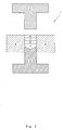
Figure 2 is a schematic section view showing an example of a compacting mold for the hard tip and a layered compact. -
Figure 3 is a perspective view showing a cutting edge tip for a drill bit as an embodiment of the hard tip of the present invention. -
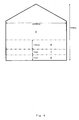
Figure 4 is a schematic view showing the thickness of each layer of a cutting edge tip as an embodiment of the present invention. -
Figure 5 is a view showing the concentration distribution of component elements of a cutting edge tip as an embodiment of the present invention from the nose side to the bonding side. -
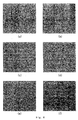
Figures 6 (a) to (f) are views showing microscope photos at various parts of the outer circumference of the major cutting edge of a cutting edge tip as an embodiment of the present invention from the bottom to the nose. -
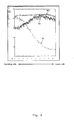
Figure 7 is a view showing cobalt concentration (percent by weight), nickel concentration (percent by weight) and Rockwell hardness (HRA) at various parts of the outer circumference of the major cutting edge of a cutting edge tip as an embodiment of the present invention from the bottom to the nose. -
Figure 8 is a schematic view showing the thickness of each layer of a cutting edge tip as another embodiment of the present invention. -
Figure 9 is a view showing the concentration distribution of component elements of a cutting edge tip as another embodiment of the present invention from the nose side to the bonding side. -
Figure 10 is a view showing cobalt concentration (percent by weight) and nickel concentration (percent by weight) at various parts of the outer circumference of the major cutting edge of a cutting edge tip as another embodiment of the present invention from the bottom to the nose. -
Figure 11 is a schematic view showing the thickness of each layer of a cutting edge tip as further another embodiment of the present invention. -
Figure 12 is a view showing the concentration distribution of component elements of a cutting edge tip as further another embodiment of the present invention from the nose side to the bonding side. -
Figure 13 is a view showing cobalt concentration (percent by weight) and nickel concentration (percent by weight) at various parts of the outer circumference of the major cutting edge of a cutting edge tip as further another embodiment of the present invention from the bottom to the nose. -
Figure 14 is a schematic section view showing another example of a compacting mold for the hard tip and a layered compact. -
Figure 15 is a schematic view showing the thickness of each layer of a cutting edge tip as still further another embodiment of the present invention. -
Figure 16 is a view showing cobalt concentration (percent by weight) and nickel concentration (percent by weight) at a portion near the bottom and another portion near the nose of the outer circumference of the major cutting edge of a cutting edge tip as still further another embodiment of the present invention. -
Figure 17 is a view showing the concentration distribution of component elements of a cutting edge tip as still further another embodiment of the present invention from the nose side to the bonding side. -
Figure 18 is a view showing a microscope photo of the nose side of a cutting edge tip as still further another embodiment of the present invention. -
Figure 19 is a view showing a microscope photo of the bonding side of a cutting edge tip as still further another embodiment of the present invention. -
Figure 20 (a) is a view showing a photo of the external appearance of a drill bit, wherein a cutting edge tip as an embodiment of the hard tip of the present invention was bonded to the end and subjected to an actual use for ten hours, andFigure 20 (b) is a view showing a photo of of the external appearance of a drill bit, wherein a cutting edge tip as a contrast of a hard tip was bonded to the end and subjected to an actual use for ten hours. -
Figure 21 is a view illustrating the average particle diameter in this description. -
Figure 22 is a view showing the phase diagram of W - C - Co ternary elements. -
Figures 23 (a) to (c) are views showing sintering processes of the bit head of the prior method for producing a drill bit. -
- 1
- compacting mold
- 2
- upper punch
- 3
- lower punch
- 4
- die
- 5
- nose layer
- 6
- first intermediate layer
- 7
- second intermediate layer
- 8
- bonding layer
- 9
- cutting edge tip
- 10
- nose side
- 11
- bonding side
- 12
- major cutting edge
- 13
- minor cutting edge
- 14
- main part of bit
- The following description of the best mode for carrying out the invention should be read with reference to the drawings wherein reference numerals indicate elements throughout plural views. The detailed description and drawings illustrate examples of various embodiments of the claimed invention, and are not intended to be limiting. It is possible to alter or modify it properly without deviating from the extent of the present invention.
- The powder comprising WC (tungsten carbide) powder of 85 percent by weight of the average particle diameter of 0.2 µm and Co (cobalt) powder of 15 percent by weight of the average particle diameter of 1.25 µm was uniformly mixed to get a first mixed powder for a nose layer. As shown in
figure 2 , the first mixed powder was feeded into compactingmold 1 consisiting ofupper punch 2,lower punch 3 and die 4 to obtain anose layer 5. Next, the powder comprising WC - Co powder of 98 percent by weight consisting of the above WC powder of 85 parts by weight and the above Co powder of 15 parts by weight and Ni (nickel) powder of 2 percent by weight of the average particle diameter of 5.0 µm was uniformly mixed to get a second mixed powder for a first intermediate layer. The second mixed powder was layered upon thenose layer 5 to obtain a firstintermediate layer 6. And the powder comprising WC - Co powder of 95 percent by weight consisting of the above WC powder of 85 parts by weight and the above Co powder of 15 parts by weight and the above Ni powder of 5 percent by weight was uniformly mixed to get a third mixed powder for a second intermediate layer. The third mixed powder was layered upon the firstintermediate layer 6 to obtain a secondintermediate layer 7. Further, the powder comprising WC - Co powder of 92 percent by weight consisting of the above WC powder of 85 parts by weight and the above Co powder of 15 parts by weight and the above Ni powder of 8 percent by weight was uniformly mixed to get a fourth mixed powder for a bonding layer. The fourth mixed powder was layered upon the secondintermediate layer 7 to obtain abonding layer 8. The layered article comprising thenose layer 5, the firstintermediate layer 6, the secondintermediate layer 7 and thebonding layer 8 was added pressure by theupper punch 2 from above to produce a layered compact whose chemical composition is gradient along the direction of height. As described above, the layered compact (compact consisting of two or more layers whose chemical composition are different one another) was produced. In the first embodiment and the other embodiments as described below, the meaning of the average particle diameter of powder will be given below. As shown infigure 21 , in case that the abscissa denotes the maximum particle diameter of powder and the ordinate denotes the quantity of powder, the average particle diameter of powder indicates the particle diameter of powder whose quantity is most. In the first embodiment, a layered compact whose chemical composition is gradient along the direction of height was produced by layering in order of the first intermediate layer, the second intermediate layer and the bonding layer upon the nose layer. But, in reverse order, that is, it is possible to produce a layered compact whose chemical composition is gradient along the direction of height by layering in order of the second intermediate layer, the first intermediate layer and the nose layer upon the bonding layer. - The above layered compact was put in a vacuum heating furnace (not shown). The pressure in the vacuum heating furnace was reduced to 200 Pa and heated up to the temperature of 1400 °C. The layered compact was sintered at the temperature of 1400 °C for 40 minutes and the pressure of 200 Pa. The sintering which is carried out under a lower pressure than atmospheric pressure (1013 hectopascals) is generally called vacuum sintering. The heating was carried out under nitrogen gas condition to prevent the oxidation of the material.
- A
cutting edge tip 9 as shown infigure 3 was obtained by the above vacuum sintering.Figure 4 is a schematic view showing the thickness of each layer of thecutting edge tip 9 obtained as described above. -
Figure 5 is a view showing the concentration distribution of component elements of thecutting edge tip 9 shown infigure 3 from the sharp tip (the nose side) 10 to the bottom (the bonding side) 11 which was measured by a scanning electron microscope. The content of WC (tungsten carbide) is inceased a little from the bonding side to the nose side. But a compounding ratio of WC to Co is nearly the same from the nose side to the bonding side. Nickel shows a gradient chemical composition where the content is increased from the nose side to the bonding side. -
Figures 6 (a) is a view showing a 4000-power microscope photo of the nose (seefigure 7 , "f") of amajor cutting edge 12 of thecutting edge tip 9 shown infigure 3 .Figures 6 (b) is a view showing a 4000-power microscope photo at 8 mm above the bottom (seefigure 7 , "e") of amajor cutting edge 12.Figures 6 (c) is a view showing a 4000-power microscope photo at 6 mm above the bottom (seefigure 7 , "d") of amajor cutting edge 12.Figures 6 (d) is a view showing a 4000-power microscope photo at 4 mm above the bottom (seefigure 7 , "c") of amajor cutting edge 12.Figures 6 (e) is a view showing a 4000-power microscope photo at 2 mm above the bottom (seefigure 7 , "b") of amajor cutting edge 12.Figures 6 (f) is a view showing a 4000-power microscope photo of the bottom (seefigure 7 , "a") of amajor cutting edge 12. As shown in microscope photos offigures 6(a) to (f), the sintered texture is satisfactorily fine without coarse inclusion -
Figure 7 is a view showing cobalt concentration (percent by weight), nickel concentration (percent by weight) and Rockwell hardness (HRA) at various parts "a" to "f " of the outer circumference of themajor cutting edge 12 of thecutting edge tip 9 shown infigure 3 from the bottom to the nose. As shown infigure 7 , the nose side where the content of the bonding metal (Co and Ni) is small is hard but the bottom (the bonding side) where the content of the bonding metal (Co and Ni) is large is soft. Thus,figure 7 shows the hardness distribution suitable for machining function required to the cutting edge tip. - As the second embodiment, the layered compact, which consists of four layers comprising the nose layer, the first intermediate layer, the second intermediate layer and the bonding layer with the same compounding ratio as the first embodiment, was produced by the same condition as the first embodiment. The above layered compact was put in a vacuum heating furnace (not shown). The pressure in the vacuum heating furnace was reduced to 200 Pa and heated up to the temperature of 1470 °C. The layered compact was sintered at the temperature of 1470 °C for 40 minutes and the pressure of 200 Pa. The vacuum sintering was carried out like this. The heating was carried out under nitrogen gas condition to prevent the oxidation of the material.
- A
cutting edge tip 9 as shown infigure 3 was obtained by the above vacuum sintering.Figure 8 is a schematic view showing the thickness of each layer of thecutting edge tip 9 obtained as described above. -
Figure 9 is a view showing the concentration distribution of component elements of the cutting edge tip obtained as described above from the sharp tip (the nose side) to the bottom (the bonding side) which was measured by a scanning electron microscope. Nickel shows a gradient chemical composition where the content is increased from the nose side to the bonding side.Figure 10 shows cobalt concentration (percent by weight) and nickel concentration (percent by weight) at various parts "n" to "r " of the outer circumference of the major cutting edge of the cutting edge tip from the bottom to the nose. As shown infigure 10 , nickel concentration (percent by weight) at the nose is more than 0.5 percent by weight. - Thus, since nickel diffuses toward the nose by sintering at the temperature over the melting point of nickel, the hardness of the nose side tends to lower.
- The powder comprising WC (tungsten carbide) powder of 90 percent by weight of the average particle diameter of 0.9 µm and Co (cobalt) powder of 10 percent by weight of the average particle diameter of 1.25 µm was uniformly mixed to get a first mixed powder for a nose layer. As shown in
figure 2 , the first mixed powder was feeded into the compactingmold 1 consisiting of theupper punch 2, thelower punch 3 and thedie 4 to obtain anose layer 5. Next, the powder comprising WC - Co powder of 95 percent by weight consisting of the above WC powder of 90 parts by weight and the above Co powder of 10 parts by weight and Ni (nickel) powder of 5 percent by weight of the average particle diameter of 5.0 µm was uniformly mixed to get a second mixed powder for a first intermediate layer. The second mixed powder was layered upon thenose layer 5 to obtain a firstintermediate layer 6. And the powder comprising WC - Co powder of 90 percent by weight consisting of the above WC powder of 90 parts by weight and the above Co powder of 10 parts by weight and the above Ni powder of 10 percent by weight was uniformly mixed to get a third mixed powder for a second intermediate layer. The third mixed powder was layered upon the firstintermediate layer 6 to obtain a secondintermediate layer 7. Further, the powder comprising WC - Co powder of 85 percent by weight consisting of the above WC powder of 90 parts by weight and the above Co powder of 10 parts by weight and the above Ni powder of 15 percent by weight was uniformly mixed to get a fourth mixed powder for a bonding layer. The fourth mixed powder was layered upon the secondintermediate layer 7 to obtain abonding layer 8.
The layered article comprising thenose layer 5, the firstintermediate layer 6, the secondintermediate layer 7 and thebonding layer 8 was added pressure by theupper punch 2 from above to produce a layered compact whose chemical composition is gradient along the direction of height. As described above, the layered compact was produced. - Next, the above layered compact was put in a vacuum heating furnace (not shown). The pressure in the vacuum heating furnace was reduced to 200 Pa and heated up to the temperature of 1550 °C. The layered compact was sintered at the temperature of 1550 °C for 40 minutes and the pressure of 200 Pa. The vacuum sintering was carried out like this. The heating was carried out under nitrogen gas condition to prevent the oxidation of the material.
- A
cutting edge tip 9 as shown infigure 3 was obtained by the above vacuum sintering.Figure 11 is a schematic view showing the thickness of each layer of thecutting edge tip 9 obtained as described above. -
Figure 12 is a view showing the concentration distribution of component elements of the cutting edge tip obtained as described above from the sharp tip (the nose side) to the bottom (the bonding side) which was measured by a scanning electron microscope. The followingtabel 1 shows the distance from the bottom at various parts of the outer circumference of the major cutting edge of thecutting edge tip 9 and cobalt concentration (percent by weight), nickel concentration (percent by weight) and Rockwell hardness (HRA) thereof.Figure 13 is a view showing cobalt concentration (percent by weight) and nickel concentration (percent by weight) extracted from Table 1. - As shown in
figure 12 , nickel shows a gradient chemical composition where the content is increased from the nose side to the bonding side. But, as shown in table 1, the nickel content is more than 1.5 percent by weight at 11 mm distant from the bottom (the point extremely near the nose, seefigure 13 ) and it can be recognized that nickel diffuses toward the nose. -
Table 1 the distance from the bottom (mm) content (percent by weight) Hardness (HRA) Co Ni the sum of Co and Ni 0.1 6.028 8.424 14.452 86.3 1 6.376 8.416 14.792 85.9 2 6.906 7.913 14.819 85.7 3 8.085 7.837 15.592 85.8 4 8.565 6.362 14.927 86.1 5 8.338 4.760 13.098 86.8 6 9.945 4.204 14.149 86.7 7 9.746 3.155 12.901 87.0 8 9.517 2.383 11.900 87.8 9 9.955 1.969 11.924 87.8 10 9.799 1.757 11.566 87.5 11 9.184 1.558 10.742 87.9 - Thus, since nickel diffuses toward the nose by sintering at the temperature over the melting point of nickel, the hardness of the nose side tends to lower.
- The powder comprising WC (tungsten carbide) powder of 92 percent by weight of the average particle diameter of 0.9 µm and Co (cobalt) powder of 8 percent by weight of the average particle diameter of 1.25 µm was uniformly mixed to get a first mixed powder for a nose layer. As shown in
figure 14 , the first mixed powder was feeded into the compactingmold 1 consisiting of theupper punch 2, thelower punch 3 and thedie 4 to obtain anose layer 5. Next, the powder comprising WC - Co powder of 95 percent by weight consisting of the above WC powder of 92 parts by weight and the above Co powder of 8 parts by weight and Cr (chromium) powder of 5 percent by weight of the average particle diameter of 10.0 µm was uniformly mixed to get a second mixed powder for a bonding layer. The second mixed powder was layered upon thenose layer 5 to obtain abonding layer 8. The layered article comprising thenose layer 5 and thebonding layer 8 was added pressure by theupper punch 2 from above to produce a layered compact whose chemical composition is gradient along the direction of height. As described above, the layered compact was produced. - Next, the above layered compact was put in a vacuum heating furnace (not shown). The pressure in the vacuum heating furnace was reduced to 200 Pa and heated up to the temperature of 1400 °C. The layered compact was sintered at the temperature of 1400 °C for 40 minutes and the pressure of 200 Pa. The vacuum sintering was carried out like this. The heating was carried out under nitrogen gas condition to prevent the oxidation of the material.
- A
cutting edge tip 9 as shown infigure 3 was obtained by the above vacuum sintering.Figure 15 is a schematic view showing the thickness of each layer of thecutting edge tip 9 obtained as described above.Figure 16 is a view showing cobalt concentration (percent by weight) and nickel concentration (percent by weight) at a portion near the bottom and another portion near the nose of the outer circumference of the major cutting edge of thecutting edge tip 9 obtained as described above. -
Figure 17 is a view showing the concentration distribution of component elements of the cutting edge tip obtained as described above from the sharp tip (the nose side) to the bottom (the bonding side) which was measured by a scanning electron microscope. The content of tungsten carbide (WC) does not so much change from the bonding side to the nose side. Chromium (Cr) shows a gradient chemical composition where the content is increased from the nose side to the bonding side. The content of cobalt (Co) widely changes from the nose side to the bonding side. -
Figures 18 is a view showing a 4000-power microscope photo of the nose side of the cutting edge tip obtained as described above.Figures 19 is a view showing a 4000-power microscope photo of the bonding side of the cutting edge tip obtained as described above. It is recognized that the texture of the bonding side shown infigure19 is finized (becoming minute) in comparison with the texture of the nose side shown infigure 18 . The sum (11.338 percent by weight, seefigure 16 ) of content of cobalt and chromium at the bonding side corresponding to the above microscope photo outnumbers the sum (8.527 percent by weight, seefigure 16 ) of content of cobalt and chromium at the nose side corresponding to the above microscope photo. But, Rockwell hardness (HRA) at the nose side was 90.6 and Rockwell hardness (HRA) at the bonding side was 92.0 corresponding to the upper limit which Rockwell hardness measuring instrument can read. Accordinglty, it is considered that the real Rockwell hardness (HRA) at the bonding side is more than 92.0. Thus, in case chromium is added as a bonding metal, the chemical composition is gradient, but it can be recognized that the texture is finized by sintering and the hardness tends to be increased. -
Figure 1 is a front view showing the important part of a drill bit whose part is omitted, wherein acutting edge tip 9 obtained as described above was bonded to amain part 14 of bit by resistance welding. -
Figure 20 (a) is a view showing an enlarged photo of the external appearance including the bonding part of a drill bit, wherein thecutting edge tip 9 obtained by the first embodiment was bonded to themain part 14 of drill bit made of chromium-molybdenum steel by resistance welding and subjected to the boring of concrete for ten hours. It can be recognized that the bonding part is not damaged after the actual use for ten hours, not to mention the time of bonding. -
Figure 20 (b) is a view showing an enlarged photo of the external appearance of a drill bit, wherein a cutting edge tip as a contrast was bonded to the main part of drill bit and subjected to the boring of concrete. This cutting edge tip as the contrast was obtained as described below. The powder comprising WC (tungsten carbide) powder of 85 percent by weight of the average particle diameter of 0.2 µm and Co (cobalt) powder of 15 percent by weight of the average particle diameter of 1.25 µm was uniformly mixed to get a mixed powder. The mixed powder was feeded into the compactingmold 1 having a section as shown infigure 2 . A compact was obtained by the same process as described above. Next, the compact was put in a vacuum heating furnace (not shown). The pressure in the vacuum heating furnace (nitrogen gas condition) was reduced to 200 Pa and heated up to the temperature of 1400 °C. The compact was sintered at the temperature of 1400 °C for 40 minutes and the pressure of 200 Pa. The vacuum sintering was carried out like this. - The
cutting edge tip 9a as the contrast was bonded to themain part 14a of drill bit made of chromium-molybdenum steel by resistance welding and subjected to the boring of concrete. Thecutting edge tip 9a was not damaged at the time of bonding.
But, at three hours after the beginning of boring, thecutting edge tip 9a came off themain part 14a of drill bit as shown infigure 20(b) . This cutting edge tip as the contrast has the features that the chemical composition is not gardient, and a monolayer of nearly uniform chemical composition constitutes the cutting edge tip from the nose side to the bonding side, and the bonding side is not provided with toughness. On the other hand, a complex residual stress is created at the bonding part of the cutting edge tip and the main part of the drill bit because of the difference of coefficient of thermal expansion between the cutting edge tip and the main part of the drill bit having different chemical components each other. As a result, thecutting edge tip 9a came off themain part 14a of the drill bit by the complex residual stress. - The hard tip of the present invention is suitable for the material of the noze of various machining tools and cutting tools such as a drill bit, a tip saw, an weed cutting machine, a saw or the like.
Claims (2)
- A hard tip consisting of block made of WC - Co sintered hard alloy wherein the chemical composition of sintered hard alloy constituting the hard tip is characterized in that a compounding ratio of WC to Co is substantially the same from a nose side to a bonding side, a first bonding metal or a second bonding metal has a gradient chemical composition wherein the content of the first bonding metal or the second bonding metal is increased from the nose side to the bonding side, the first bonding metal does not form the eutectic texture with WC, and the second bonding metal has the eutectic temperature with WC over the eutectic temperature of WC - Co sintered hard alloy and the melting point over the liquid phase sintering temperature of WC - Co sintered hard alloy.
- A method for producing a hard tip where a compounding ratio of WC to Co is substantially the same at each layer from the nose layer of a nose side to the bonding layer of a bonding side via intermediate layer(s) of one or more, a first bonding metal or a second bonding metal has a gradient chemical composition wherein the content of the first bonding metal or the second bonding metal is increased from the nose side to the bonding side, the first bonding metal does not form the eutectic texture with WC, and the second bonding metal has the eutectic temperature with WC over the eutectic temperature of WC - Co sintered hard alloy and the melting point over the liquid phase sintering temperature of WC - Co sintered hard alloy, comprising the following processes of a first prosess, a second process, a third process and a fourth process ;
A first process being a stage of feeding, sintered hard alloy powder for the nose layer containing a required compounding ratio of WC to Co and a smallest quantity of a bonding metal, into a compacting mold for the hard tip,
A second process being a stage of layering, sintered hard alloy powder for intermediate layer(s) of one or more comprising a required compounding ratio of WC to Co and the bonding metal whose content is gradually increasing compared with the nose layer, upon the nose layer in the compacting mold for the hard tip,
A third process being a stage of layering, sintered hard alloy powder for the bonding layer comprising a required compounding ratio of WC to Co and a largest quantity of the bonding metal, upon the intermediate layer(s) in the compacting mold for the hard tip and adding pressure to obtain a compact, and
A fourth process being a stage of putting the compact in a heating furnace and sintering at a temperature of melting point or less of the bonding metal and a lower pressure than atmospheric pressure to produce the hard tip.
Applications Claiming Priority (1)
| Application Number | Priority Date | Filing Date | Title |
|---|---|---|---|
| PCT/JP2006/323124 WO2008062505A1 (en) | 2006-11-20 | 2006-11-20 | Superhard tip and process for producing the same |
Publications (3)
| Publication Number | Publication Date |
|---|---|
| EP2093301A1 true EP2093301A1 (en) | 2009-08-26 |
| EP2093301A4 EP2093301A4 (en) | 2009-12-16 |
| EP2093301B1 EP2093301B1 (en) | 2019-03-20 |
Family
ID=39429446
Family Applications (1)
| Application Number | Title | Priority Date | Filing Date |
|---|---|---|---|
| EP06832974.7A Active EP2093301B1 (en) | 2006-11-20 | 2006-11-20 | Superhard tip and process for producing the same |
Country Status (11)
| Country | Link |
|---|---|
| US (2) | US20100003093A1 (en) |
| EP (1) | EP2093301B1 (en) |
| JP (1) | JP5191394B2 (en) |
| KR (1) | KR20090086965A (en) |
| CN (1) | CN101605919B (en) |
| AU (1) | AU2006351038B2 (en) |
| BR (1) | BRPI0622005A2 (en) |
| CA (1) | CA2667323C (en) |
| ES (1) | ES2720062T3 (en) |
| HK (1) | HK1137490A1 (en) |
| WO (1) | WO2008062505A1 (en) |
Cited By (1)
| Publication number | Priority date | Publication date | Assignee | Title |
|---|---|---|---|---|
| CN108620595A (en) * | 2018-04-03 | 2018-10-09 | 鑫京瑞钨钢(厦门)有限公司 | Hard alloy screw nut mold with multilayered and graded structure and its manufacturing method |
Families Citing this family (11)
| Publication number | Priority date | Publication date | Assignee | Title |
|---|---|---|---|---|
| DE102011081948B4 (en) * | 2011-09-01 | 2013-05-23 | Hilti Aktiengesellschaft | Drill and manufacturing process for a drill |
| JP6339436B2 (en) * | 2014-07-29 | 2018-06-06 | 京セラ株式会社 | Drill blank, drill blank manufacturing method, and drill |
| JP2016108668A (en) * | 2014-12-05 | 2016-06-20 | 株式会社日立製作所 | Composite member and manufacturing method of composite member |
| JP2016177385A (en) * | 2015-03-18 | 2016-10-06 | 株式会社リコー | Information processing apparatus, information processing method, and program |
| EP3117939A1 (en) * | 2015-07-14 | 2017-01-18 | HILTI Aktiengesellschaft | Tool |
| CN106424740B (en) * | 2016-09-30 | 2019-04-12 | 昆明理工大学 | A kind of tungsten carbide granule reinforced steel matrix skin layer composite material and preparation method thereof |
| EP3342516A1 (en) | 2017-01-02 | 2018-07-04 | HILTI Aktiengesellschaft | Tool |
| JP6209300B1 (en) | 2017-04-27 | 2017-10-04 | 日本タングステン株式会社 | Anvil roll, rotary cutter, and workpiece cutting method |
| WO2019069701A1 (en) * | 2017-10-02 | 2019-04-11 | 日立金属株式会社 | Cemented carbide composite material, method for producing same, and cemented carbide tool |
| CN111390183A (en) * | 2020-04-22 | 2020-07-10 | 重庆辰罡科技有限公司 | Manufacturing process of hard alloy, metal cutting tool and die |
| CN114147227B (en) * | 2021-12-10 | 2022-10-11 | 哈尔滨理工大学 | Bionic cutter based on bamboo fiber cell wall annular multi-wall-layer structure and preparation method thereof |
Citations (2)
| Publication number | Priority date | Publication date | Assignee | Title |
|---|---|---|---|---|
| US4398952A (en) * | 1980-09-10 | 1983-08-16 | Reed Rock Bit Company | Methods of manufacturing gradient composite metallic structures |
| JPH09315873A (en) * | 1996-05-28 | 1997-12-09 | Sumitomo Coal Mining Co Ltd | Sintered hard alloy based wear resistant material and its production |
Family Cites Families (16)
| Publication number | Priority date | Publication date | Assignee | Title |
|---|---|---|---|---|
| US4595062A (en) * | 1980-07-17 | 1986-06-17 | Varco International, Inc. | Well casing jack mechanism |
| EP0194018A1 (en) | 1985-01-31 | 1986-09-10 | Boart International Limited | Forming components made of hard metal |
| JPS6263005A (en) | 1985-09-11 | 1987-03-19 | Nachi Fujikoshi Corp | Drill |
| US5305840A (en) * | 1992-09-14 | 1994-04-26 | Smith International, Inc. | Rock bit with cobalt alloy cemented tungsten carbide inserts |
| JPH06263005A (en) * | 1993-03-12 | 1994-09-20 | Suzuki Motor Corp | Seat belt device |
| DE4339245A1 (en) | 1993-11-18 | 1995-05-24 | Hilti Ag | Twist drill |
| JPH08100589A (en) | 1994-09-30 | 1996-04-16 | Eagle Ind Co Ltd | Bit for excavation and manufacture thereof |
| JP2896749B2 (en) | 1994-12-16 | 1999-05-31 | イーグル工業株式会社 | Drilling bit and manufacturing method thereof |
| US5679445A (en) * | 1994-12-23 | 1997-10-21 | Kennametal Inc. | Composite cermet articles and method of making |
| JP2004292905A (en) * | 2003-03-27 | 2004-10-21 | Tungaloy Corp | Compositionally graded sintered alloy and method of producing the same |
| US20050211475A1 (en) * | 2004-04-28 | 2005-09-29 | Mirchandani Prakash K | Earth-boring bits |
| US7699904B2 (en) * | 2004-06-14 | 2010-04-20 | University Of Utah Research Foundation | Functionally graded cemented tungsten carbide |
| JP2006118033A (en) | 2004-10-25 | 2006-05-11 | Hokkaido | Method for producing compositionally gradient cemented carbide |
| US7887747B2 (en) * | 2005-09-12 | 2011-02-15 | Sanalloy Industry Co., Ltd. | High strength hard alloy and method of preparing the same |
| EP2184122A1 (en) * | 2008-11-11 | 2010-05-12 | Sandvik Intellectual Property AB | Cemented carbide body and method |
| US8440314B2 (en) * | 2009-08-25 | 2013-05-14 | TDY Industries, LLC | Coated cutting tools having a platinum group metal concentration gradient and related processes |
-
2006
- 2006-11-20 BR BRPI0622005-3A patent/BRPI0622005A2/en not_active IP Right Cessation
- 2006-11-20 US US12/446,720 patent/US20100003093A1/en not_active Abandoned
- 2006-11-20 EP EP06832974.7A patent/EP2093301B1/en active Active
- 2006-11-20 WO PCT/JP2006/323124 patent/WO2008062505A1/en active Application Filing
- 2006-11-20 CA CA2667323A patent/CA2667323C/en active Active
- 2006-11-20 KR KR1020097008672A patent/KR20090086965A/en not_active Application Discontinuation
- 2006-11-20 JP JP2008545264A patent/JP5191394B2/en active Active
- 2006-11-20 ES ES06832974T patent/ES2720062T3/en active Active
- 2006-11-20 CN CN2006800564205A patent/CN101605919B/en active Active
- 2006-11-20 AU AU2006351038A patent/AU2006351038B2/en not_active Ceased
-
2010
- 2010-03-04 HK HK10102326.9A patent/HK1137490A1/en not_active IP Right Cessation
-
2013
- 2013-11-15 US US14/081,415 patent/US9463507B2/en active Active
Patent Citations (2)
| Publication number | Priority date | Publication date | Assignee | Title |
|---|---|---|---|---|
| US4398952A (en) * | 1980-09-10 | 1983-08-16 | Reed Rock Bit Company | Methods of manufacturing gradient composite metallic structures |
| JPH09315873A (en) * | 1996-05-28 | 1997-12-09 | Sumitomo Coal Mining Co Ltd | Sintered hard alloy based wear resistant material and its production |
Non-Patent Citations (1)
| Title |
|---|
| See also references of WO2008062505A1 * |
Cited By (2)
| Publication number | Priority date | Publication date | Assignee | Title |
|---|---|---|---|---|
| CN108620595A (en) * | 2018-04-03 | 2018-10-09 | 鑫京瑞钨钢(厦门)有限公司 | Hard alloy screw nut mold with multilayered and graded structure and its manufacturing method |
| CN108620595B (en) * | 2018-04-03 | 2019-06-04 | 鑫京瑞钨钢(厦门)有限公司 | Hard alloy screw nut mold and its manufacturing method with multilayered and graded structure |
Also Published As
| Publication number | Publication date |
|---|---|
| CN101605919B (en) | 2012-08-29 |
| CA2667323A1 (en) | 2008-05-29 |
| JP5191394B2 (en) | 2013-05-08 |
| EP2093301B1 (en) | 2019-03-20 |
| US20140072468A1 (en) | 2014-03-13 |
| CA2667323C (en) | 2012-10-30 |
| EP2093301A4 (en) | 2009-12-16 |
| KR20090086965A (en) | 2009-08-14 |
| AU2006351038B2 (en) | 2011-08-18 |
| US20100003093A1 (en) | 2010-01-07 |
| CN101605919A (en) | 2009-12-16 |
| WO2008062505A1 (en) | 2008-05-29 |
| JPWO2008062505A1 (en) | 2010-03-04 |
| BRPI0622005A2 (en) | 2011-12-20 |
| HK1137490A1 (en) | 2010-08-27 |
| AU2006351038A1 (en) | 2008-05-29 |
| ES2720062T3 (en) | 2019-07-17 |
| US9463507B2 (en) | 2016-10-11 |
Similar Documents
| Publication | Publication Date | Title |
|---|---|---|
| US9463507B2 (en) | Method for producing hard tip | |
| US4686080A (en) | Composite compact having a base of a hard-centered alloy in which the base is joined to a substrate through a joint layer and process for producing the same | |
| EP3069806B1 (en) | Diamond bonded body, tool provided with same, and method for producing diamond bonded body | |
| US8490721B2 (en) | Polycrystalline diamond | |
| US7575620B2 (en) | Infiltrant matrix powder and product using such powder | |
| RU2521937C2 (en) | Hard alloy body | |
| JP3046336B2 (en) | Sintered alloy with graded composition and method for producing the same | |
| JP5413047B2 (en) | Composite sintered body | |
| KR20130040769A (en) | Sintered cubic boron nitride tool | |
| KR20210084337A (en) | Cemented carbide, cutting tool and manufacturing method of cemented carbide | |
| Ellis et al. | Cermets | |
| RU2424875C2 (en) | Hard-alloy tip and method of its production | |
| JPH0798964B2 (en) | Cubic boron nitride cemented carbide composite sintered body | |
| JP2019210184A (en) | Base material and cutting tool | |
| JP2002013377A (en) | Excavation tool having brazed join part of cutting edge piece having excellent resistance against impact and join strength | |
| JPH0431012B2 (en) | ||
| JPH1192852A (en) | Intergranular metal dispersion strengthened wc-containing cemented carbide and its production | |
| JPH0564695B2 (en) | ||
| JP2000129387A (en) | Composite material for brazing containing cubic boron nitride, and its manufacture | |
| JP2018111108A (en) | Composite member and cutting tool comprising the composite member | |
| JP2020157453A (en) | Diamond-coated cemented carbide tool | |
| JP2000129315A (en) | Diamond-containing composite material for brazing and its production |
Legal Events
| Date | Code | Title | Description |
|---|---|---|---|
| PUAI | Public reference made under article 153(3) epc to a published international application that has entered the european phase |
Free format text: ORIGINAL CODE: 0009012 |
|
| 17P | Request for examination filed |
Effective date: 20090512 |
|
| AK | Designated contracting states |
Kind code of ref document: A1 Designated state(s): AT BE BG CH CY CZ DE DK EE ES FI FR GB GR HU IE IS IT LI LT LU LV MC NL PL PT RO SE SI SK TR |
|
| A4 | Supplementary search report drawn up and despatched |
Effective date: 20091118 |
|
| DAX | Request for extension of the european patent (deleted) | ||
| 17Q | First examination report despatched |
Effective date: 20130621 |
|
| STAA | Information on the status of an ep patent application or granted ep patent |
Free format text: STATUS: EXAMINATION IS IN PROGRESS |
|
| GRAP | Despatch of communication of intention to grant a patent |
Free format text: ORIGINAL CODE: EPIDOSNIGR1 |
|
| STAA | Information on the status of an ep patent application or granted ep patent |
Free format text: STATUS: GRANT OF PATENT IS INTENDED |
|
| RIC1 | Information provided on ipc code assigned before grant |
Ipc: B22F 7/06 20060101ALI20180821BHEP Ipc: C22C 29/08 20060101AFI20180821BHEP Ipc: B22F 5/00 20060101ALI20180821BHEP |
|
| INTG | Intention to grant announced |
Effective date: 20180926 |
|
| GRAS | Grant fee paid |
Free format text: ORIGINAL CODE: EPIDOSNIGR3 |
|
| GRAA | (expected) grant |
Free format text: ORIGINAL CODE: 0009210 |
|
| STAA | Information on the status of an ep patent application or granted ep patent |
Free format text: STATUS: THE PATENT HAS BEEN GRANTED |
|
| AK | Designated contracting states |
Kind code of ref document: B1 Designated state(s): AT BE BG CH CY CZ DE DK EE ES FI FR GB GR HU IE IS IT LI LT LU LV MC NL PL PT RO SE SI SK TR |
|
| REG | Reference to a national code |
Ref country code: GB Ref legal event code: FG4D |
|
| REG | Reference to a national code |
Ref country code: CH Ref legal event code: EP |
|
| REG | Reference to a national code |
Ref country code: DE Ref legal event code: R096 Ref document number: 602006057655 Country of ref document: DE |
|
| REG | Reference to a national code |
Ref country code: AT Ref legal event code: REF Ref document number: 1110587 Country of ref document: AT Kind code of ref document: T Effective date: 20190415 |
|
| REG | Reference to a national code |
Ref country code: IE Ref legal event code: FG4D |
|
| REG | Reference to a national code |
Ref country code: CH Ref legal event code: NV Representative=s name: VALIPAT S.A. C/O BOVARD SA NEUCHATEL, CH |
|
| REG | Reference to a national code |
Ref country code: ES Ref legal event code: FG2A Ref document number: 2720062 Country of ref document: ES Kind code of ref document: T3 Effective date: 20190717 |
|
| REG | Reference to a national code |
Ref country code: NL Ref legal event code: MP Effective date: 20190320 |
|
| PG25 | Lapsed in a contracting state [announced via postgrant information from national office to epo] |
Ref country code: LT Free format text: LAPSE BECAUSE OF FAILURE TO SUBMIT A TRANSLATION OF THE DESCRIPTION OR TO PAY THE FEE WITHIN THE PRESCRIBED TIME-LIMIT Effective date: 20190320 Ref country code: FI Free format text: LAPSE BECAUSE OF FAILURE TO SUBMIT A TRANSLATION OF THE DESCRIPTION OR TO PAY THE FEE WITHIN THE PRESCRIBED TIME-LIMIT Effective date: 20190320 Ref country code: SE Free format text: LAPSE BECAUSE OF FAILURE TO SUBMIT A TRANSLATION OF THE DESCRIPTION OR TO PAY THE FEE WITHIN THE PRESCRIBED TIME-LIMIT Effective date: 20190320 |
|
| REG | Reference to a national code |
Ref country code: LT Ref legal event code: MG4D |
|
| PG25 | Lapsed in a contracting state [announced via postgrant information from national office to epo] |
Ref country code: GR Free format text: LAPSE BECAUSE OF FAILURE TO SUBMIT A TRANSLATION OF THE DESCRIPTION OR TO PAY THE FEE WITHIN THE PRESCRIBED TIME-LIMIT Effective date: 20190621 Ref country code: LV Free format text: LAPSE BECAUSE OF FAILURE TO SUBMIT A TRANSLATION OF THE DESCRIPTION OR TO PAY THE FEE WITHIN THE PRESCRIBED TIME-LIMIT Effective date: 20190320 Ref country code: BG Free format text: LAPSE BECAUSE OF FAILURE TO SUBMIT A TRANSLATION OF THE DESCRIPTION OR TO PAY THE FEE WITHIN THE PRESCRIBED TIME-LIMIT Effective date: 20190620 Ref country code: NL Free format text: LAPSE BECAUSE OF FAILURE TO SUBMIT A TRANSLATION OF THE DESCRIPTION OR TO PAY THE FEE WITHIN THE PRESCRIBED TIME-LIMIT Effective date: 20190320 |
|
| PG25 | Lapsed in a contracting state [announced via postgrant information from national office to epo] |
Ref country code: SK Free format text: LAPSE BECAUSE OF FAILURE TO SUBMIT A TRANSLATION OF THE DESCRIPTION OR TO PAY THE FEE WITHIN THE PRESCRIBED TIME-LIMIT Effective date: 20190320 Ref country code: PT Free format text: LAPSE BECAUSE OF FAILURE TO SUBMIT A TRANSLATION OF THE DESCRIPTION OR TO PAY THE FEE WITHIN THE PRESCRIBED TIME-LIMIT Effective date: 20190720 Ref country code: CZ Free format text: LAPSE BECAUSE OF FAILURE TO SUBMIT A TRANSLATION OF THE DESCRIPTION OR TO PAY THE FEE WITHIN THE PRESCRIBED TIME-LIMIT Effective date: 20190320 Ref country code: RO Free format text: LAPSE BECAUSE OF FAILURE TO SUBMIT A TRANSLATION OF THE DESCRIPTION OR TO PAY THE FEE WITHIN THE PRESCRIBED TIME-LIMIT Effective date: 20190320 Ref country code: EE Free format text: LAPSE BECAUSE OF FAILURE TO SUBMIT A TRANSLATION OF THE DESCRIPTION OR TO PAY THE FEE WITHIN THE PRESCRIBED TIME-LIMIT Effective date: 20190320 |
|
| PG25 | Lapsed in a contracting state [announced via postgrant information from national office to epo] |
Ref country code: PL Free format text: LAPSE BECAUSE OF FAILURE TO SUBMIT A TRANSLATION OF THE DESCRIPTION OR TO PAY THE FEE WITHIN THE PRESCRIBED TIME-LIMIT Effective date: 20190320 |
|
| PG25 | Lapsed in a contracting state [announced via postgrant information from national office to epo] |
Ref country code: IS Free format text: LAPSE BECAUSE OF FAILURE TO SUBMIT A TRANSLATION OF THE DESCRIPTION OR TO PAY THE FEE WITHIN THE PRESCRIBED TIME-LIMIT Effective date: 20190720 |
|
| REG | Reference to a national code |
Ref country code: DE Ref legal event code: R097 Ref document number: 602006057655 Country of ref document: DE |
|
| PLBE | No opposition filed within time limit |
Free format text: ORIGINAL CODE: 0009261 |
|
| STAA | Information on the status of an ep patent application or granted ep patent |
Free format text: STATUS: NO OPPOSITION FILED WITHIN TIME LIMIT |
|
| PG25 | Lapsed in a contracting state [announced via postgrant information from national office to epo] |
Ref country code: DK Free format text: LAPSE BECAUSE OF FAILURE TO SUBMIT A TRANSLATION OF THE DESCRIPTION OR TO PAY THE FEE WITHIN THE PRESCRIBED TIME-LIMIT Effective date: 20190320 |
|
| 26N | No opposition filed |
Effective date: 20200102 |
|
| PG25 | Lapsed in a contracting state [announced via postgrant information from national office to epo] |
Ref country code: SI Free format text: LAPSE BECAUSE OF FAILURE TO SUBMIT A TRANSLATION OF THE DESCRIPTION OR TO PAY THE FEE WITHIN THE PRESCRIBED TIME-LIMIT Effective date: 20190320 |
|
| PG25 | Lapsed in a contracting state [announced via postgrant information from national office to epo] |
Ref country code: TR Free format text: LAPSE BECAUSE OF FAILURE TO SUBMIT A TRANSLATION OF THE DESCRIPTION OR TO PAY THE FEE WITHIN THE PRESCRIBED TIME-LIMIT Effective date: 20190320 |
|
| PG25 | Lapsed in a contracting state [announced via postgrant information from national office to epo] |
Ref country code: MC Free format text: LAPSE BECAUSE OF FAILURE TO SUBMIT A TRANSLATION OF THE DESCRIPTION OR TO PAY THE FEE WITHIN THE PRESCRIBED TIME-LIMIT Effective date: 20190320 |
|
| REG | Reference to a national code |
Ref country code: BE Ref legal event code: MM Effective date: 20191130 |
|
| PG25 | Lapsed in a contracting state [announced via postgrant information from national office to epo] |
Ref country code: IE Free format text: LAPSE BECAUSE OF NON-PAYMENT OF DUE FEES Effective date: 20191120 |
|
| PG25 | Lapsed in a contracting state [announced via postgrant information from national office to epo] |
Ref country code: BE Free format text: LAPSE BECAUSE OF NON-PAYMENT OF DUE FEES Effective date: 20191130 |
|
| PG25 | Lapsed in a contracting state [announced via postgrant information from national office to epo] |
Ref country code: CY Free format text: LAPSE BECAUSE OF FAILURE TO SUBMIT A TRANSLATION OF THE DESCRIPTION OR TO PAY THE FEE WITHIN THE PRESCRIBED TIME-LIMIT Effective date: 20190320 |
|
| REG | Reference to a national code |
Ref country code: AT Ref legal event code: UEP Ref document number: 1110587 Country of ref document: AT Kind code of ref document: T Effective date: 20190320 |
|
| PG25 | Lapsed in a contracting state [announced via postgrant information from national office to epo] |
Ref country code: HU Free format text: LAPSE BECAUSE OF FAILURE TO SUBMIT A TRANSLATION OF THE DESCRIPTION OR TO PAY THE FEE WITHIN THE PRESCRIBED TIME-LIMIT; INVALID AB INITIO Effective date: 20061120 |
|
| PGFP | Annual fee paid to national office [announced via postgrant information from national office to epo] |
Ref country code: LU Payment date: 20231120 Year of fee payment: 18 |
|
| PGFP | Annual fee paid to national office [announced via postgrant information from national office to epo] |
Ref country code: GB Payment date: 20231123 Year of fee payment: 18 |
|
| PGFP | Annual fee paid to national office [announced via postgrant information from national office to epo] |
Ref country code: ES Payment date: 20231213 Year of fee payment: 18 |
|
| PGFP | Annual fee paid to national office [announced via postgrant information from national office to epo] |
Ref country code: IT Payment date: 20231120 Year of fee payment: 18 Ref country code: FR Payment date: 20231120 Year of fee payment: 18 Ref country code: DE Payment date: 20231121 Year of fee payment: 18 Ref country code: CH Payment date: 20231201 Year of fee payment: 18 Ref country code: AT Payment date: 20231121 Year of fee payment: 18 |