EP2093110A1 - Parkbremse - Google Patents
Parkbremse Download PDFInfo
- Publication number
- EP2093110A1 EP2093110A1 EP09100111A EP09100111A EP2093110A1 EP 2093110 A1 EP2093110 A1 EP 2093110A1 EP 09100111 A EP09100111 A EP 09100111A EP 09100111 A EP09100111 A EP 09100111A EP 2093110 A1 EP2093110 A1 EP 2093110A1
- Authority
- EP
- European Patent Office
- Prior art keywords
- parking brake
- piston
- spring
- electric motor
- brake according
- Prior art date
- Legal status (The legal status is an assumption and is not a legal conclusion. Google has not performed a legal analysis and makes no representation as to the accuracy of the status listed.)
- Granted
Links
- 210000000629 knee joint Anatomy 0.000 claims description 4
- 238000011161 development Methods 0.000 description 3
- 230000018109 developmental process Effects 0.000 description 3
- 238000009434 installation Methods 0.000 description 3
- 230000004913 activation Effects 0.000 description 2
- 230000005540 biological transmission Effects 0.000 description 1
- 239000003990 capacitor Substances 0.000 description 1
- 230000001419 dependent effect Effects 0.000 description 1
- 238000010586 diagram Methods 0.000 description 1
- 238000006073 displacement reaction Methods 0.000 description 1
- 210000003127 knee Anatomy 0.000 description 1
- 238000000926 separation method Methods 0.000 description 1
Images

Classifications
-
- B—PERFORMING OPERATIONS; TRANSPORTING
- B60—VEHICLES IN GENERAL
- B60T—VEHICLE BRAKE CONTROL SYSTEMS OR PARTS THEREOF; BRAKE CONTROL SYSTEMS OR PARTS THEREOF, IN GENERAL; ARRANGEMENT OF BRAKING ELEMENTS ON VEHICLES IN GENERAL; PORTABLE DEVICES FOR PREVENTING UNWANTED MOVEMENT OF VEHICLES; VEHICLE MODIFICATIONS TO FACILITATE COOLING OF BRAKES
- B60T7/00—Brake-action initiating means
- B60T7/02—Brake-action initiating means for personal initiation
- B60T7/04—Brake-action initiating means for personal initiation foot actuated
- B60T7/042—Brake-action initiating means for personal initiation foot actuated by electrical means, e.g. using travel or force sensors
-
- B—PERFORMING OPERATIONS; TRANSPORTING
- B60—VEHICLES IN GENERAL
- B60T—VEHICLE BRAKE CONTROL SYSTEMS OR PARTS THEREOF; BRAKE CONTROL SYSTEMS OR PARTS THEREOF, IN GENERAL; ARRANGEMENT OF BRAKING ELEMENTS ON VEHICLES IN GENERAL; PORTABLE DEVICES FOR PREVENTING UNWANTED MOVEMENT OF VEHICLES; VEHICLE MODIFICATIONS TO FACILITATE COOLING OF BRAKES
- B60T13/00—Transmitting braking action from initiating means to ultimate brake actuator with power assistance or drive; Brake systems incorporating such transmitting means, e.g. air-pressure brake systems
- B60T13/74—Transmitting braking action from initiating means to ultimate brake actuator with power assistance or drive; Brake systems incorporating such transmitting means, e.g. air-pressure brake systems with electrical assistance or drive
- B60T13/746—Transmitting braking action from initiating means to ultimate brake actuator with power assistance or drive; Brake systems incorporating such transmitting means, e.g. air-pressure brake systems with electrical assistance or drive and mechanical transmission of the braking action
Definitions
- the invention relates to a parking brake for commercial vehicles according to the preamble of claim 1.
- a parking brake also called parking brake
- a spring-loaded brake cylinder which applies the brake due to the spring force and in which the brake is released by compressed air and held in the release position.
- the compressed air acts on a displaceable piston which tensions the spring (cf. Bosch, Kraftfahrisches Taschenbuch, 22nd edition, Dusseldorf, VDI-Verlag, 1995, p. 248 ).
- the actuating device for the parking brake consists of a pneumatic valve, which is usually located in the cab. In trailer vehicles can also be provided that the parking brake is automatically applied as soon as a pressure line between towing vehicle and trailer is disconnected.
- the object of the invention is to simplify the parking brake of the type mentioned. This object is achieved by the features specified in claim 1. Advantageous embodiments and further developments of the invention can be found in the dependent claims.
- the basic idea of the invention is to operate the spring brake of the parking brake electromechanically. In other words, the previous pneumatic cylinder by an electromechanical drive, such as an electric motor, an electromagnet or other electrically powered Linear actuator replaced. As a result, the complex installation of compressed air lines is avoided and it is only an electrical cable needed to operate the parking brake.
- the electric motor drive via a tension member or a linkage is connected to the displaceable piston, that the combination of traction element or linkage and drive occupies an over-center position. This ensures that no holding current is needed for the driving position, in which the spring tensioned and the parking brake is released.
- the electromotive drive is a gear motor with self-locking gear, such. a check transmission. Again, no holding current is required for the release position.
- the parking brake has an electronic control with its own electrical power supply, which automatically activates the parking brake in case of failure of the vehicle electrical system , For this purpose, only a small amount of energy is required to move back, for example, the electric motor drive with the linkage on the over-center position, the further movement of the piston for applying the brake is then effected by the spring.
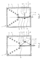
- the parking brake 1 has a housing 2, in which a piston 3 is displaceably guided with a piston rod 4.
- the piston rod 4 operates in a known manner braking members, such as. Brake shoes.
- the piston 3 is biased by a spring 5, wherein the spring 5 is supported on the one hand on the housing and on the other hand on the piston 3.
- the piston 3 is coupled via a tension member 6, which is here a rod, articulated with an electric motor 7. If a rod is used, its one end is connected to the piston via a first joint 8 and to the electric motor 7 via a second joint 9, the second joint 9 being mounted eccentrically to the axis of rotation of the electric motor 7, for example on a rotatable disk 10 or a rotatably connected to the electric motor 7 lever 11th
- a projection 13 is mounted, which cooperates with a mounted on the housing 2 stop 14 and as from FIG. 2 can be seen, the rotation limited and indeed in such a position that the tension member 6 enters a "Übertot Vietnamese simply" in which a straight line connecting the two joints 8 and 9 with respect to the axis of rotation of the electric motor 7 has changed the page.
- this connection line is to the left of the axis of rotation, while in FIG. 2 is right of the axis of rotation and thus this has just cut in the "dead center", while she has changed in the over-center position, the page.
- the electric motor 7 opposite to the direction of the arrow 12 of FIG. 1 be briefly rotated until the described dead center is exceeded. Subsequently, the spring 5 acts and presses the piston 3 together with the piston rod 4 in the parking brake position.
- a control device 15 may be provided that may be arranged in the housing 2 or outside of the housing 2.
- the control unit 15 is controlled via an electrical line 16 and possibly a terminal 17.
- the electric motor 7 can be driven in both directions, for applying and releasing the parking brake.
- the controller 15 may have an electronic circuit with its own power supply.
- the power supply may be an accumulator or a capacitor.
- the electronic circuit then monitors whether a vehicle electrical system voltage is present and, if the vehicle electrical system voltage fails, activates a rotary drive of the electric motor 7 in the direction of applying the brake.
- the electric motor 7 must be driven only briefly to the in FIG. 2 overcome overterting position shown, whereupon the application of the brake takes place solely under the action of the spring 5.
- FIGS. 3 and 4 show a second embodiment in which the electromechanical drive is realized by an electromagnet 18 in combination with a toggle lever assembly 19, 20.
- the toggle lever assembly has two levers 19 and 20.
- the first lever 19 is connected via the first joint 8 with the piston 3.
- the second lever 20 is connected via the second joint 9 with the housing, wherein both levers 19 and 20 are connected via a knee joint 21 with each other and with a linearly displaceable armature of the electromagnet 18.
- the electromagnet when it is electrically energized, pushes with its armature 22 against the knee joint 21 and thus presses the piston 3 and the piston rod 4 against the force of the spring 5, wherein here too an over-center position the knee lever assembly is provided for the release position in which the knee joint 21 has changed the side with respect to a longitudinal axis of the piston rod 4. This over-center position is ensured by an already existing in the electromagnet movement limitation.
- the electromagnet 18 is designed so that its armature 22 can be actively moved in both directions. To apply the parking brake, the armature 22 must move the toggle lever arrangement 19, 20 only via the dead center position. The further movement to the parking position of FIG. 3 is here again automatically effected by the spring 5. Again, a control device 15 may be provided, which analogous to the embodiment of Figures 1 and 2 the electromagnet 18 controls, if automatic activation of the parking brake is desired.
Landscapes
- Engineering & Computer Science (AREA)
- Transportation (AREA)
- Mechanical Engineering (AREA)
- Braking Arrangements (AREA)
- Braking Systems And Boosters (AREA)
Abstract
Description
- Die Erfindung bezieht sich auf eine Parkbremse für Nutzfahrzeuge gemäß dem Oberbegriff des Patentanspruches 1.
- Nutzfahrzeuge haben üblicherweise eine Parkbremse (auch Feststellbremse genannt) mit einem Federspeicher-Bremszylinder, der aufgrund der Federkraft die Bremse anlegt und bei der die Bremse durch Druckluft gelöst und in der Lösestellung gehalten wird. Die Druckluft wirkt dabei auf einen verschieblichen Kolben, der die Feder spannt (vgl. Bosch, Kraftfahrtechnisches Taschenbuch, 22. Auflage, Düsseldorf, VDI-Verlag, 1995, S. 248).
- Die Betätigungseinrichtung für die Parkbremse besteht dabei aus einem pneumatischen Ventil, das üblicherweise im Fahrerhaus angeordnet ist. Bei Anhängerfahrzeugen kann auch vorgesehen sein, daß die Parkbremse automatisch angelegt wird, sobald eine Druckleitung zwischen Zugfahrzeug und Anhänger getrennt wird.
- Nachteil dieser rein pneumatisch arbeitenden Parkbremse ist die aufwendige Verlegung von Druckluftleitungen sowie die Notwendigkeit eines pneumatischen Steuerventils.
- Aufgabe der Erfindung ist es, die Parkbremse der eingangs genannten Art zu vereinfachen. Diese Aufgabe wird durch die im Patentanspruch 1 angegebenen Merkmale gelöst. Vorteilhafte Ausgestaltungen und Weiterbildungen der Erfindung sind den Unteransprüchen zu entnehmen. Der Grundgedanke der Erfindung liegt darin, den Federspeicher der Parkbremse elektromechanisch zu betätigen. Mit anderen Worten wird der bisherige Druckluftzylinder durch einen elektromechanischen Antrieb, wie z.B. einen Elektromotor, einen Elektromagneten oder sonstiges elektrisch angetriebenes Linear-Betätigungsorgan ersetzt. Hierdurch wird die aufwendige Verlegung von Druckluftleitungen vermieden und es wird lediglich ein elektrisches Kabel zur Betätigung der Parkbremse benötigt.
- Nach einer Weiterbildung der Erfindung ist der elektromotorische Antrieb über ein Zugorgan oder ein Gestänge so mit dem verschieblichen Kolben verbunden, daß die Kombination aus Zugorgan bzw. Gestänge und Antrieb eine Übertotpunktstellung einnimmt. Damit wird erreicht, daß für die Fahrtstellung, bei der die Feder gespannt und die Parkbremse gelöst ist, kein Haltestrom benötigt wird.
- Nach einer anderen Weiterbildung der Erfindung ist der elektromotorische Antrieb ein Getriebemotor mit selbsthemmendem Getriebe, wie z.B. einem Scheckengetriebe. Auch hier wird kein Haltestrom für die Lösestellung benötigt.
- Für den Fall, daß ein automatisches Aktivieren der Parkbremse bei Zugtrennung erfolgen soll, was beispielsweise bei Anhängerfahrzeugen erwünscht ist, sieht eine Weiterbildung der Erfindung vor, daß die Parkbremse eine elektronische Steuerung mit eigener elektrischer Energieversorgung aufweist, die bei Ausfall der Bordnetzspannung die Parkbremse automatisch aktiviert. Hierzu wird nur eine geringe Energie benötigt, um beispielsweise den elektromotorischen Antrieb mit dem Gestänge über die Übertotpunktstellung zurückzubewegen, wobei die weitere Bewegung des Kolbens zum Anlegen der Bremse dann durch die Feder bewirkt wird.
- Im folgenden wird die Erfindung anhand von Ausführungsbeispielen im Zusammenhang mit der Zeichnung ausführlicher erläutert. Es zeigt:
- Figur 1
- eine geschnittene Prinzipskizze der Parkbremse nach einem ersten Ausführungsbeispiel in der Parkstellung;
- Figur 2
- dieselbe Parkbremse in der Lösestellung;
- Figur 3
- ein zweites Ausführungsbeispiel einer Parkbremse in Bremsstellung; und
- Figur 4
- die Parkbremse der
Figur 3 in Lösestellung. - Die Parkbremse 1 hat ein Gehäuse 2, in dem ein Kolben 3 mit einer Kolbenstange 4 verschieblich geführt ist. Die Kolbenstange 4 betätigt in bekannter Weise Bremsorgane, wie z.B. Bremsbacken. Der Kolben 3 ist durch eine Feder 5 vorgespannt, wobei sich die Feder 5 einerseits am Gehäuse und andererseits am Kolben 3 abstützt.
- Der Kolben 3 ist über ein Zugorgan 6, das hier eine Stange ist, mit einem Elektromotor 7 gelenkig gekoppelt. Wird eine Stange verwendet, so ist ihr eines Ende über ein erstes Gelenk 8 mit dem Kolben und über ein zweites Gelenk 9 mit dem Elektromotor 7 verbunden, wobei das zweite Gelenk 9 exzentrisch zur Drehachse des Elektromotors 7 angebracht ist, beispielsweise an einer drehbaren Scheibe 10 oder einem drehfest mit dem Elektromotor 7 verbundenen Hebel 11.
- Wird der Elektromotor 7 in der in
Figur 1 dargestellten Stellung in Richtung des Pfeiles 12 drehangetrieben, so werden der Kolben 3 und die Kolbenstange 4 in das Gehäuse 2 hineingezogen und die Feder 5 wird gespannt. - An der Scheibe 10 bzw. dem Hebel 11 ist ein Vorsprung 13 angebracht, der mit einem am Gehäuse 2 angebrachten Anschlag 14 zusammenwirkt und wie aus
Figur 2 zu erkennen ist, die Drehung begrenzt und zwar in solcher Lage, daß das Zugorgan 6 in eine "Übertotpunktstellung" gelangt, in welcher eine gerade Verbindungslinie zwischen den beiden Gelenken 8 und 9 gegenüber der Drehachse des Elektromotors 7 die Seite gewechselt hat. In der Darstellung derFigur 1 liegt diese Verbindungslinie links von der Drehachse, während sie inFigur 2 rechts von der Drehachse liegt und diese somit in der "Totpunktstellung" gerade geschnitten hat, während sie in der Übertotpunktstellung die Seite gewechselt hat. - Die Übertotpunktstellung der
Figur 2 ist aufgrund der Kraft der Feder 5 stabil, da durch die Übertotpunktstellung ein Drehmoment auf den Elektromotor ausgeübt wird, der Drehrichtung des Pfeiles 12 derFigur 1 entgegengesetzt. Diese Übertotpunktstellung wird durch den Vorsprung 13 und den Anschlag 14 stabilisiert, so daß kein Haltestrom für den Elektromotor 7 erforderlich ist. - Zum Lösen der Parkbremse muß der Elektromotor 7 entgegen der Richtung des Pfeiles 12 der
Figur 1 kurzfristig drehangetrieben werden, bis die beschriebene Totpunktlage überschritten ist. Anschließend wirkt die Feder 5 und drückt den Kolben 3 samt Kolbenstange 4 in die Parkbremsstellung. - Zur Steuerung des Elektromotors 7 kann ein Steuergerät 15 vorgesehen sein, daß im Gehäuse 2 oder außerhalb des Gehäuses 2 angeordnet sein kann. Das Steuergerät 15 ist über eine elektrische Leitung 16 und ggf. eine Anschlußklemme 17 ansteuerbar.
- Über das Steuergerät 15 kann der Elektromotor 7 in beiden Drehrichtungen angetrieben werden, zum Anlegen und Lösen der Parkbremse.
- Für bestimmte Anwendungsfälle, bei denen ein automatisches Anlegen der Parkbremse gewünscht ist, kann das Steuergerät 15 eine elektronische Schaltung mit einer eigenen Energieversorgung aufweisen. Die Energieversorgung kann ein Akkumulator oder auch ein Kondensator sein. Die elektronische Schaltung überwacht dann, ob eine Bordnetzspannung vorhanden ist und aktiviert bei Ausfall der Bordnetzspannung einen Drehantrieb des Elektromotors 7 in Richtung eines Anlegens der Bremse. Hierzu muß der Elektromotor 7 nur kurzfristig angetrieben werden, um die in
Figur 2 dargestellte Übertotpunktstellung zu überwinden, worauf anschließend das Anlegen der Bremse allein unter Wirkung der Feder 5 erfolgt. - Die
Figuren 3 und 4 zeigen ein zweites Ausführungsbeispiel, bei dem der elektromechanische Antrieb durch einen Elektromagneten 18 in Kombination mit einer Kniehebelanordnung 19, 20 realisiert ist. - Die Kniehebelanordnung hat zwei Hebel 19 und 20. Der erste Hebel 19 ist über das erste Gelenk 8 mit dem Kolben 3 verbunden. Der zweite Hebel 20 ist über das zweite Gelenk 9 mit dem Gehäuse verbunden, wobei beide Hebel 19 und 20 über ein Kniegelenk 21 miteinander sowie mit einem linear verschieblichen Anker des Elektromagneten 18 verbunden sind. Der Elektromagnet drückt, wenn er elektrisch erregt ist, mit seinem Anker 22 gegen das Kniegelenk 21 und drückt damit den Kolben 3 und die Kolbenstange 4 gegen die Kraft der Feder 5, wobei auch hier eine Übertotpunktstellung der Kniehebelanordnung für die Lösestellung vorgesehen ist, in welcher das Kniegelenk 21 gegenüber einer Längsachse der Kolbenstange 4 die Seite gewechselt hat. Diese Übertotpunktstellung wird durch einen ohnehin im Elektromagneten vorhandene Bewegungsbegrenzung sichergestellt. Der Elektromagnet 18 ist so ausgelegt, daß sein Anker 22 aktiv in beiden Richtungen verschoben werden kann. Zum Anlegen der Parkbremse muß der Anker 22 die Kniehebelanordnung 19, 20 lediglich über die Totpunktlage bewegen. Die weitere Bewegung zur Parkstellung der
Figur 3 wird auch hier wiederum automatisch durch die Feder 5 bewirkt. Auch hier kann ein Steuergerät 15 vorgesehen sein, das analog dem Ausführungsbeispiel derFiguren 1 und 2 den Elektromagneten 18 ansteuert, falls eine automatische Aktivierung der Parkbremse erwünscht ist. - Abschließend sei darauf hingewiesen, daß selbstverständlich auch andere Antriebsarten möglich sind, beispielsweise ein Elektromotor, der über ein Ritzel eine Zahnstange antreibt, ein Elektromotor, der eine Seilwinde für das Zugorgan 6 antreibt, das dann ein flexibler Draht oder ähnliches ist, sowie jegliche sonstige elektromotorischen Antriebe, die eine Linearverschiebung des Kolbens 3 und der Kolbenstange 4 bewirken können.
- Zusammengefaßt erreicht man mit der Erfindung wesentliche Vorteile. Der Bauraumbedarf gegenüber herkömmlichen Federspeicherbremsen ist geringer. Der Aufwand für die Verlegung von Druckluftleitungen wird vermieden. Es werden keine aktiven Verriegelungseinheiten benötigt, um die Parkbremse gelöst zu halten.
Claims (8)
- Parkbremse mit einem Federspeicher, der einen von einer Feder beaufschlagten verschieblichen Kolben aufweist, gekennzeichnet durch einen elektrischen Antrieb (7; 18), der so angeordnet ist, daß er den Kolben (3) gegen die Kraft der Feder (5) verschiebt.
- Parkbremse nach Anspruch 1, dadurch gekennzeichnet, daß der elektrische Antrieb ein Elektromotor (7) ist, der über ein Zugorgan (6) mit dem Kolben (3) verbunden ist.
- Parkbremse nach Anspruch 2, dadurch gekennzeichnet, daß der Elektromotor (7) einen Drehbegrenzungsanschlag (13, 14) aufweist und daß das Zugorgan (6) bei Erreichen des Drehbegrenzungsanschlages (13, 14) in einer Übertotpunktstellung ist.
- Parkbremse nach Anspruch 2, dadurch gekennzeichnet, daß der Elektromotor (7) ein Getriebemotor mit einem selbsthemmenden Getriebe ist.
- Parkbremse nach Anspruch 1, dadurch gekennzeichnet, daß der elektrische Antrieb ein Linearantrieb (18) ist, der über eine Kniehebelanordnung (19, 20) mit dem Kolben (3) gekoppelt ist.
- Parkbremse nach Anspruch 5, dadurch gekennzeichnet, daß der Linearantrieb ein Elektromagnet (18) mit einem Anker (22) ist, wobei der Anker (22) mit einem Kniegelenk (21) der Kniehebelanordnung (19, 20) gekoppelt ist.
- Parkbremse nach Anspruch 5 oder 6, dadurch gekennzeichnet, daß die Kniehebelanordnung (19, 20) so ausgelegt ist, daß sie in einer Grenzstellung des Linearantriebes in einer Übertotpunktstellung ist.
- Parkbremse nach einem der Ansprüche 1 bis 7, dadurch gekennzeichnet, daß sie ein elektrisches Steuergerät (15) aufweist, welches eine eigene elektrische Energieversorgung hat und daß das Steuergerät (15) so ausgebildet ist, daß es bei Ausfall einer Bordnetzspannung den elektrischen Antrieb (7, 18) in Richtung zu einer Parkstellung der Parkbremse antreibt.
Applications Claiming Priority (1)
| Application Number | Priority Date | Filing Date | Title |
|---|---|---|---|
| DE102008009946A DE102008009946A1 (de) | 2008-02-20 | 2008-02-20 | Parkbremse |
Publications (2)
| Publication Number | Publication Date |
|---|---|
| EP2093110A1 true EP2093110A1 (de) | 2009-08-26 |
| EP2093110B1 EP2093110B1 (de) | 2012-04-18 |
Family
ID=40474769
Family Applications (1)
| Application Number | Title | Priority Date | Filing Date |
|---|---|---|---|
| EP09100111A Not-in-force EP2093110B1 (de) | 2008-02-20 | 2009-02-13 | Parkbremse |
Country Status (3)
| Country | Link |
|---|---|
| EP (1) | EP2093110B1 (de) |
| AT (1) | ATE553968T1 (de) |
| DE (1) | DE102008009946A1 (de) |
Cited By (1)
| Publication number | Priority date | Publication date | Assignee | Title |
|---|---|---|---|---|
| CN109334650A (zh) * | 2016-07-29 | 2019-02-15 | 金福珍 | 自动化程度较高的车辆电子驻车制动装置 |
Families Citing this family (2)
| Publication number | Priority date | Publication date | Assignee | Title |
|---|---|---|---|---|
| DE102012104674A1 (de) * | 2012-05-30 | 2013-12-05 | Tüschen & Zimmermann Gmbh & Co. Kg | Vorrichtung zum Lüften und automatischen Betätigen einer Bremseinrichtung |
| DE102013203118A1 (de) * | 2013-02-26 | 2014-08-28 | Trumpf Medizin Systeme Gmbh + Co. Kg | Elektromechanisch lösbare Bremse für eine medizinische Versorgungseinheit |
Citations (5)
| Publication number | Priority date | Publication date | Assignee | Title |
|---|---|---|---|---|
| US4546298A (en) * | 1983-05-12 | 1985-10-08 | Westinghouse Brake & Signal Co. | Electric actuators |
| DE102004043309A1 (de) * | 2003-12-17 | 2005-07-21 | Continental Teves Ag & Co. Ohg | Hydraulische Fahrzeugbremse |
| DE102005001234A1 (de) * | 2005-01-11 | 2006-07-20 | Wabco Gmbh & Co.Ohg | Bremszylinder mit Parkbremsfunktion |
| DE102005022400A1 (de) * | 2005-05-13 | 2006-11-16 | Robert Bosch Gmbh | Hydraulische Fahrzeugbremse mit Feststelleinrichtung und Verfahren zur Funktionsüberprüfung der Feststellbremse |
| US20070068749A1 (en) * | 2005-09-29 | 2007-03-29 | Peter Ullmann | Apparatus and method for actuating a parking brake of a vehicle |
-
2008
- 2008-02-20 DE DE102008009946A patent/DE102008009946A1/de not_active Withdrawn
-
2009
- 2009-02-13 AT AT09100111T patent/ATE553968T1/de active
- 2009-02-13 EP EP09100111A patent/EP2093110B1/de not_active Not-in-force
Patent Citations (5)
| Publication number | Priority date | Publication date | Assignee | Title |
|---|---|---|---|---|
| US4546298A (en) * | 1983-05-12 | 1985-10-08 | Westinghouse Brake & Signal Co. | Electric actuators |
| DE102004043309A1 (de) * | 2003-12-17 | 2005-07-21 | Continental Teves Ag & Co. Ohg | Hydraulische Fahrzeugbremse |
| DE102005001234A1 (de) * | 2005-01-11 | 2006-07-20 | Wabco Gmbh & Co.Ohg | Bremszylinder mit Parkbremsfunktion |
| DE102005022400A1 (de) * | 2005-05-13 | 2006-11-16 | Robert Bosch Gmbh | Hydraulische Fahrzeugbremse mit Feststelleinrichtung und Verfahren zur Funktionsüberprüfung der Feststellbremse |
| US20070068749A1 (en) * | 2005-09-29 | 2007-03-29 | Peter Ullmann | Apparatus and method for actuating a parking brake of a vehicle |
Cited By (1)
| Publication number | Priority date | Publication date | Assignee | Title |
|---|---|---|---|---|
| CN109334650A (zh) * | 2016-07-29 | 2019-02-15 | 金福珍 | 自动化程度较高的车辆电子驻车制动装置 |
Also Published As
| Publication number | Publication date |
|---|---|
| DE102008009946A1 (de) | 2009-09-03 |
| ATE553968T1 (de) | 2012-05-15 |
| EP2093110B1 (de) | 2012-04-18 |
Similar Documents
| Publication | Publication Date | Title |
|---|---|---|
| EP3691943B1 (de) | Mechanische bremsvorrichtung | |
| DE102009057376B4 (de) | Sicherheitsbremsvorrichtung für ein Fahrzeug | |
| DE102009055639B4 (de) | Bremssystem | |
| EP0877693B1 (de) | Kombinierte betriebs- und feststellbremsanlage | |
| DE69920133T2 (de) | Feststellbremsung bei Fahrzeugen | |
| DE69931453T2 (de) | Feststellbremse für Kraftfahrzeuge | |
| EP2744692B1 (de) | Elektromechanischer bremskraftverstärker | |
| DE102008054852A1 (de) | Elektromechanischer Bremskraftverstärker | |
| WO2013079667A2 (de) | Federspeicherbremszylinder mit notlöseeinrichtung | |
| DE102017008196A1 (de) | Trommelbremse mit einem elektromechanisch-hydraulischen Bremsaktuator | |
| DE2526526A1 (de) | Bremsanlage mit einer einrichtung zur betaetigung einer not- und feststellbremse | |
| DE19705105C2 (de) | Fremdkraftunterstützte Betätigungseinrichtung für eine Feststellbremse für Fahrzeuge | |
| EP1082551B1 (de) | Aktuatorenbaugruppe für eine fahrzeugbremse und fahrzeugbremse mit einer derartigen aktuatorenbaugruppe | |
| DE102014223037A1 (de) | Parksperrenaktuator für eine Parksperre eines Kraftfahrzeug-Automatgetriebes | |
| DE102022208668A1 (de) | Elektrische feststellbremse und fahrzeug mit derselben | |
| EP2093110B1 (de) | Parkbremse | |
| EP3076041B1 (de) | Bremsantrieb | |
| DE10340650B3 (de) | Luftfahrzeug-Fahrwerk | |
| EP0881134B1 (de) | Kraftspeicher | |
| DE102019118896A1 (de) | Parkbremseinrichtung | |
| DE102007010765A1 (de) | Elektromechanischer Kupplungsaktuator | |
| DE10201607A1 (de) | Scheibenbremse mit Betätigungsvorrichtung | |
| WO2019238173A1 (de) | Bremsvorrichtung | |
| EP4568860B1 (de) | Kompakt-bremszange mit elektromechanischem aktuator, exzenterwellenantrieb und mechanischem nachsteller, und verfahren zum betreiben einer solchen kompakt-bremszange | |
| EP1775494B1 (de) | Bremsbetätigungsvorrichtung |
Legal Events
| Date | Code | Title | Description |
|---|---|---|---|
| PUAI | Public reference made under article 153(3) epc to a published international application that has entered the european phase |
Free format text: ORIGINAL CODE: 0009012 |
|
| AK | Designated contracting states |
Kind code of ref document: A1 Designated state(s): AT BE BG CH CY CZ DE DK EE ES FI FR GB GR HR HU IE IS IT LI LT LU LV MC MK MT NL NO PL PT RO SE SI SK TR |
|
| AX | Request for extension of the european patent |
Extension state: AL BA RS |
|
| 17P | Request for examination filed |
Effective date: 20100226 |
|
| 17Q | First examination report despatched |
Effective date: 20100323 |
|
| AKX | Designation fees paid |
Designated state(s): AT BE BG CH CY CZ DE DK EE ES FI FR GB GR HR HU IE IS IT LI LT LU LV MC MK MT NL NO PL PT RO SE SI SK TR |
|
| GRAP | Despatch of communication of intention to grant a patent |
Free format text: ORIGINAL CODE: EPIDOSNIGR1 |
|
| GRAS | Grant fee paid |
Free format text: ORIGINAL CODE: EPIDOSNIGR3 |
|
| GRAA | (expected) grant |
Free format text: ORIGINAL CODE: 0009210 |
|
| AK | Designated contracting states |
Kind code of ref document: B1 Designated state(s): AT BE BG CH CY CZ DE DK EE ES FI FR GB GR HR HU IE IS IT LI LT LU LV MC MK MT NL NO PL PT RO SE SI SK TR |
|
| REG | Reference to a national code |
Ref country code: GB Ref legal event code: FG4D Free format text: NOT ENGLISH |
|
| REG | Reference to a national code |
Ref country code: CH Ref legal event code: EP |
|
| REG | Reference to a national code |
Ref country code: IE Ref legal event code: FG4D Free format text: LANGUAGE OF EP DOCUMENT: GERMAN |
|
| REG | Reference to a national code |
Ref country code: AT Ref legal event code: REF Ref document number: 553968 Country of ref document: AT Kind code of ref document: T Effective date: 20120515 |
|
| REG | Reference to a national code |
Ref country code: DE Ref legal event code: R096 Ref document number: 502009003274 Country of ref document: DE Effective date: 20120614 |
|
| REG | Reference to a national code |
Ref country code: SE Ref legal event code: TRGR |
|
| REG | Reference to a national code |
Ref country code: NL Ref legal event code: VDEP Effective date: 20120418 |
|
| LTIE | Lt: invalidation of european patent or patent extension |
Effective date: 20120418 |
|
| PG25 | Lapsed in a contracting state [announced via postgrant information from national office to epo] |
Ref country code: LT Free format text: LAPSE BECAUSE OF FAILURE TO SUBMIT A TRANSLATION OF THE DESCRIPTION OR TO PAY THE FEE WITHIN THE PRESCRIBED TIME-LIMIT Effective date: 20120418 Ref country code: NO Free format text: LAPSE BECAUSE OF FAILURE TO SUBMIT A TRANSLATION OF THE DESCRIPTION OR TO PAY THE FEE WITHIN THE PRESCRIBED TIME-LIMIT Effective date: 20120718 Ref country code: CY Free format text: LAPSE BECAUSE OF FAILURE TO SUBMIT A TRANSLATION OF THE DESCRIPTION OR TO PAY THE FEE WITHIN THE PRESCRIBED TIME-LIMIT Effective date: 20120418 Ref country code: FI Free format text: LAPSE BECAUSE OF FAILURE TO SUBMIT A TRANSLATION OF THE DESCRIPTION OR TO PAY THE FEE WITHIN THE PRESCRIBED TIME-LIMIT Effective date: 20120418 Ref country code: PL Free format text: LAPSE BECAUSE OF FAILURE TO SUBMIT A TRANSLATION OF THE DESCRIPTION OR TO PAY THE FEE WITHIN THE PRESCRIBED TIME-LIMIT Effective date: 20120418 Ref country code: IS Free format text: LAPSE BECAUSE OF FAILURE TO SUBMIT A TRANSLATION OF THE DESCRIPTION OR TO PAY THE FEE WITHIN THE PRESCRIBED TIME-LIMIT Effective date: 20120818 |
|
| PG25 | Lapsed in a contracting state [announced via postgrant information from national office to epo] |
Ref country code: PT Free format text: LAPSE BECAUSE OF FAILURE TO SUBMIT A TRANSLATION OF THE DESCRIPTION OR TO PAY THE FEE WITHIN THE PRESCRIBED TIME-LIMIT Effective date: 20120820 Ref country code: HR Free format text: LAPSE BECAUSE OF FAILURE TO SUBMIT A TRANSLATION OF THE DESCRIPTION OR TO PAY THE FEE WITHIN THE PRESCRIBED TIME-LIMIT Effective date: 20120418 Ref country code: GR Free format text: LAPSE BECAUSE OF FAILURE TO SUBMIT A TRANSLATION OF THE DESCRIPTION OR TO PAY THE FEE WITHIN THE PRESCRIBED TIME-LIMIT Effective date: 20120719 Ref country code: LV Free format text: LAPSE BECAUSE OF FAILURE TO SUBMIT A TRANSLATION OF THE DESCRIPTION OR TO PAY THE FEE WITHIN THE PRESCRIBED TIME-LIMIT Effective date: 20120418 Ref country code: SI Free format text: LAPSE BECAUSE OF FAILURE TO SUBMIT A TRANSLATION OF THE DESCRIPTION OR TO PAY THE FEE WITHIN THE PRESCRIBED TIME-LIMIT Effective date: 20120418 |
|
| PG25 | Lapsed in a contracting state [announced via postgrant information from national office to epo] |
Ref country code: CZ Free format text: LAPSE BECAUSE OF FAILURE TO SUBMIT A TRANSLATION OF THE DESCRIPTION OR TO PAY THE FEE WITHIN THE PRESCRIBED TIME-LIMIT Effective date: 20120418 Ref country code: DK Free format text: LAPSE BECAUSE OF FAILURE TO SUBMIT A TRANSLATION OF THE DESCRIPTION OR TO PAY THE FEE WITHIN THE PRESCRIBED TIME-LIMIT Effective date: 20120418 Ref country code: RO Free format text: LAPSE BECAUSE OF FAILURE TO SUBMIT A TRANSLATION OF THE DESCRIPTION OR TO PAY THE FEE WITHIN THE PRESCRIBED TIME-LIMIT Effective date: 20120418 Ref country code: SK Free format text: LAPSE BECAUSE OF FAILURE TO SUBMIT A TRANSLATION OF THE DESCRIPTION OR TO PAY THE FEE WITHIN THE PRESCRIBED TIME-LIMIT Effective date: 20120418 Ref country code: NL Free format text: LAPSE BECAUSE OF FAILURE TO SUBMIT A TRANSLATION OF THE DESCRIPTION OR TO PAY THE FEE WITHIN THE PRESCRIBED TIME-LIMIT Effective date: 20120418 Ref country code: EE Free format text: LAPSE BECAUSE OF FAILURE TO SUBMIT A TRANSLATION OF THE DESCRIPTION OR TO PAY THE FEE WITHIN THE PRESCRIBED TIME-LIMIT Effective date: 20120418 |
|
| PLBE | No opposition filed within time limit |
Free format text: ORIGINAL CODE: 0009261 |
|
| STAA | Information on the status of an ep patent application or granted ep patent |
Free format text: STATUS: NO OPPOSITION FILED WITHIN TIME LIMIT |
|
| 26N | No opposition filed |
Effective date: 20130121 |
|
| PG25 | Lapsed in a contracting state [announced via postgrant information from national office to epo] |
Ref country code: ES Free format text: LAPSE BECAUSE OF FAILURE TO SUBMIT A TRANSLATION OF THE DESCRIPTION OR TO PAY THE FEE WITHIN THE PRESCRIBED TIME-LIMIT Effective date: 20120729 |
|
| REG | Reference to a national code |
Ref country code: DE Ref legal event code: R097 Ref document number: 502009003274 Country of ref document: DE Effective date: 20130121 |
|
| PG25 | Lapsed in a contracting state [announced via postgrant information from national office to epo] |
Ref country code: BG Free format text: LAPSE BECAUSE OF FAILURE TO SUBMIT A TRANSLATION OF THE DESCRIPTION OR TO PAY THE FEE WITHIN THE PRESCRIBED TIME-LIMIT Effective date: 20120718 |
|
| BERE | Be: lapsed |
Owner name: KNORR-BREMSE SYSTEME FUR NUTZFAHRZEUGE G.M.B.H. Effective date: 20130228 |
|
| PG25 | Lapsed in a contracting state [announced via postgrant information from national office to epo] |
Ref country code: MC Free format text: LAPSE BECAUSE OF NON-PAYMENT OF DUE FEES Effective date: 20130228 |
|
| REG | Reference to a national code |
Ref country code: CH Ref legal event code: PL |
|
| GBPC | Gb: european patent ceased through non-payment of renewal fee |
Effective date: 20130213 |
|
| PG25 | Lapsed in a contracting state [announced via postgrant information from national office to epo] |
Ref country code: LI Free format text: LAPSE BECAUSE OF NON-PAYMENT OF DUE FEES Effective date: 20130228 Ref country code: CH Free format text: LAPSE BECAUSE OF NON-PAYMENT OF DUE FEES Effective date: 20130228 |
|
| REG | Reference to a national code |
Ref country code: FR Ref legal event code: ST Effective date: 20131031 |
|
| REG | Reference to a national code |
Ref country code: IE Ref legal event code: MM4A |
|
| PG25 | Lapsed in a contracting state [announced via postgrant information from national office to epo] |
Ref country code: BE Free format text: LAPSE BECAUSE OF NON-PAYMENT OF DUE FEES Effective date: 20130228 Ref country code: GB Free format text: LAPSE BECAUSE OF NON-PAYMENT OF DUE FEES Effective date: 20130213 Ref country code: IE Free format text: LAPSE BECAUSE OF NON-PAYMENT OF DUE FEES Effective date: 20130213 Ref country code: FR Free format text: LAPSE BECAUSE OF NON-PAYMENT OF DUE FEES Effective date: 20130228 |
|
| PG25 | Lapsed in a contracting state [announced via postgrant information from national office to epo] |
Ref country code: MT Free format text: LAPSE BECAUSE OF FAILURE TO SUBMIT A TRANSLATION OF THE DESCRIPTION OR TO PAY THE FEE WITHIN THE PRESCRIBED TIME-LIMIT Effective date: 20120418 |
|
| REG | Reference to a national code |
Ref country code: AT Ref legal event code: MM01 Ref document number: 553968 Country of ref document: AT Kind code of ref document: T Effective date: 20140213 |
|
| PG25 | Lapsed in a contracting state [announced via postgrant information from national office to epo] |
Ref country code: AT Free format text: LAPSE BECAUSE OF NON-PAYMENT OF DUE FEES Effective date: 20140213 |
|
| PG25 | Lapsed in a contracting state [announced via postgrant information from national office to epo] |
Ref country code: TR Free format text: LAPSE BECAUSE OF FAILURE TO SUBMIT A TRANSLATION OF THE DESCRIPTION OR TO PAY THE FEE WITHIN THE PRESCRIBED TIME-LIMIT Effective date: 20120418 |
|
| PG25 | Lapsed in a contracting state [announced via postgrant information from national office to epo] |
Ref country code: HU Free format text: LAPSE BECAUSE OF FAILURE TO SUBMIT A TRANSLATION OF THE DESCRIPTION OR TO PAY THE FEE WITHIN THE PRESCRIBED TIME-LIMIT; INVALID AB INITIO Effective date: 20090213 Ref country code: MK Free format text: LAPSE BECAUSE OF FAILURE TO SUBMIT A TRANSLATION OF THE DESCRIPTION OR TO PAY THE FEE WITHIN THE PRESCRIBED TIME-LIMIT Effective date: 20120418 Ref country code: LU Free format text: LAPSE BECAUSE OF NON-PAYMENT OF DUE FEES Effective date: 20130213 |
|
| PGFP | Annual fee paid to national office [announced via postgrant information from national office to epo] |
Ref country code: IT Payment date: 20190222 Year of fee payment: 11 Ref country code: DE Payment date: 20190219 Year of fee payment: 11 |
|
| PGFP | Annual fee paid to national office [announced via postgrant information from national office to epo] |
Ref country code: SE Payment date: 20190221 Year of fee payment: 11 |
|
| REG | Reference to a national code |
Ref country code: DE Ref legal event code: R119 Ref document number: 502009003274 Country of ref document: DE |
|
| REG | Reference to a national code |
Ref country code: SE Ref legal event code: EUG |
|
| PG25 | Lapsed in a contracting state [announced via postgrant information from national office to epo] |
Ref country code: SE Free format text: LAPSE BECAUSE OF NON-PAYMENT OF DUE FEES Effective date: 20200214 |
|
| PG25 | Lapsed in a contracting state [announced via postgrant information from national office to epo] |
Ref country code: DE Free format text: LAPSE BECAUSE OF NON-PAYMENT OF DUE FEES Effective date: 20200901 |
|
| PG25 | Lapsed in a contracting state [announced via postgrant information from national office to epo] |
Ref country code: IT Free format text: LAPSE BECAUSE OF NON-PAYMENT OF DUE FEES Effective date: 20200213 |