EP2092850A1 - Fitting for a corner cupboard - Google Patents
Fitting for a corner cupboard Download PDFInfo
- Publication number
- EP2092850A1 EP2092850A1 EP08003326A EP08003326A EP2092850A1 EP 2092850 A1 EP2092850 A1 EP 2092850A1 EP 08003326 A EP08003326 A EP 08003326A EP 08003326 A EP08003326 A EP 08003326A EP 2092850 A1 EP2092850 A1 EP 2092850A1
- Authority
- EP
- European Patent Office
- Prior art keywords
- tray
- fitting
- support arm
- fitting according
- hand
- Prior art date
- Legal status (The legal status is an assumption and is not a legal conclusion. Google has not performed a legal analysis and makes no representation as to the accuracy of the status listed.)
- Granted
Links
Images


Classifications
-
- A—HUMAN NECESSITIES
- A47—FURNITURE; DOMESTIC ARTICLES OR APPLIANCES; COFFEE MILLS; SPICE MILLS; SUCTION CLEANERS IN GENERAL
- A47B—TABLES; DESKS; OFFICE FURNITURE; CABINETS; DRAWERS; GENERAL DETAILS OF FURNITURE
- A47B81/00—Cabinets or racks specially adapted for other particular purposes, e.g. for storing guns or skis
- A47B81/002—Corner cabinets; Cabinets designed for being placed in a corner or a niche
Definitions
- the tray is thus forced by the fitting according to the invention on a guideway, which prevents a large and thus relatively much space-consuming "Ausholzi” takes place within the corner cabinet.
- the tray can be dimensioned larger overall. Accordingly, of course, increases the footprint for abinnede objects.
- the control single lever in combination with the support arm, it is possible Control device and support arm to place relatively close to each other, whereby a Eckbackside attachment to only one area is necessary.
- the two known from the prior art handlebars are pivotally mounted at two spaced apart locations of the Eck jetperipherie.
- the fitting according to the invention is therefore relatively compact overall. The installation in the corner cabinet and the attachment of the tray is easy and quick to carry out.
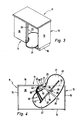
- the Fig. 1 to 6 show a first embodiment of the invention Eck Os 11 and the built-in inventive fitting 12.
- the corner cabinet 11 has a cabinet body 13, which is exemplified with a rectangular plan.
- the cabinet body 13 in turn consists of a rear wall 14, two side walls 15, 16 and a front side 17, which in turn is subdivided into a front wall 18 and a corner cabinet door (not shown) arranged adjacent thereto. Furthermore, a cabinet bottom 19 is still provided.
- Front wall 18 and corner door take the front 17 in about equal parts.
- the rectangular cabinet body 13 defines a correspondingly rectangular interior 20, which is accessible in about half of the corner cabinet door.
- the interior of the corner cupboard 11 is at least one tray 21, which by means of the fitting 12 between an inner position in which the tray 21 completely in the interior 20th is housed, and an outdoor position in which the tray 21 at least partially beyond a plane 22 of a door opening of the corner cupboard 11 protrudes, is movably controlled.
- a single tray 21 is shown here.
- two or more superimposed shelves 21 are arranged.
- the tray 21 is exemplified in one-piece embodiment.
- the fixed hinge axes 42, 43 with respect to the fixed pivot axis 24 of the support arm 26 on the same side of the support arm 26 are the two stationary hinge axes 42, 43 relatively close together.
Abstract
Description
Die Erfindung betrifft einen Beschlag für einen Eckschrank, insbesondere Kücheneckschrank, mit einem Schrankkorpus und einem über eine Eckschranktür zugänglichen Innenraum, in dem wenigstens ein Tablar mittels des Beschlags zwischen einer Innenstellung und einer Außenstellung, in der das Tablar zumindest teilweise über eine Ebene einer Türöffnung hinaussteht, beweglich geführt ist, wobei der Beschlag wenigstens einen einerseits um eine im eingebauten Zustand des Tablars ortsfeste Schwenkachse schwenkbar gelagerten und andererseits an einer Lagerstelle schwenkbar am zugeordneten Tablar gelagerten Tragarm zur Tablarabstützung und wenigstens eine Steuereinrichtung zur Steuerung der Tablarbewegung zwischen der Innen- und der Außenstellung aufweist.The invention relates to a fitting for a corner cabinet, in particular Kücheneckschrank, with a cabinet body and accessible via a corner door interior in which at least one tray by means of the fitting between an inner position and an outer position, in which the tray at least partially beyond a plane of a door opening , is movably guided, wherein the fitting at least one pivotally mounted on the one hand to a fixed in the installed state of the tray pivot axis and on the other hand mounted on a bearing point pivotally mounted on the associated tray support for Tablarabstützung and at least one control device for controlling the Tablarbewegung between the inner and the outer position having.
Ein Beschlag dieser Art ist aus der
Aufgabe der Erfindung ist es daher, einen Beschlag der eingangs erwähnten Art zu schaffen, mit dem der im Eckschrank zur Verfügung stehende Platz durch dementsprechende Dimensionierung des wenigstens einen Tablars optimal genutzt wird.The object of the invention is therefore to provide a fitting of the type mentioned, with which the space available in the corner cupboard space is optimally used by corresponding dimensioning of at least one tray.
Diese Aufgabe wird durch einen Beschlag mit den Merkmalen des unabhängigen Anspruchs 1 gelöst. Weiterbildungen der Erfindung sind in den Unteransprüchen dargestellt.This object is achieved by a fitting with the features of the independent claim 1. Further developments of the invention are shown in the subclaims.
Der erfindungsgemäße Beschlag zeichnet sich dadurch aus, dass die Steuereinrichtung einen ersten Steuer-Einzelhebel und einen zweiten Steuer-Einzelhebel aufweist, die jeweils einerseits um eine ortsfeste Gelenkachse und andererseits um eine tablarfeste Schwenkachse schwenkbar gelagert sind, wobei die beiden tablarfesten Schwenkachsen in Bezug auf die Lagerstelle des Tragarms an der selben Tablarseite angeordnet sind.The fitting according to the invention is characterized in that the control device has a first control single lever and a second control single lever, which are pivotally mounted on the one hand about a fixed hinge axis and on the other hand to a tablarfeste pivot axis, wherein the two tablarfesten pivot axes with respect to the Bearing point of the support arm are arranged on the same tray side.
Das Tablar wird also durch den erfindungsgemäßen Beschlag auf eine Führungsbahn gezwungen, die verhindert, dass eine große und damit relativ viel Platz beanspruchende "Ausholbewegung" innerhalb des Eckschrankes stattfindet. Dadurch kann das Tablar insgesamt größer dimensioniert werden. Dementsprechend vergrößert sich natürlich auch die Stellfläche für darauf abzustellende Gegenstände. Durch den Einsatz der Steuer-Einzelhebel in Kombination mit den Tragarm ist es möglich, Steuereinrichtung und Tragarm relativ dicht beieinander zu platzieren, wodurch eine eckschrankseitige Befestigung an nur einem Bereich notwendig ist. Im Gegensatz hierzu sind die beiden aus dem Stand der Technik bekannten Lenker an zwei mit großen Abstand zueinander liegenden Stellen der Eckschrankperipherie schwenkbar gelagert. Der erfindungsgemäße Beschlag ist also insgesamt relativ kompakt. Der Einbau in den Eckschrank und die Befestigung des Tablars ist einfach und schnell durchführbar.The tray is thus forced by the fitting according to the invention on a guideway, which prevents a large and thus relatively much space-consuming "Ausholbewegung" takes place within the corner cabinet. As a result, the tray can be dimensioned larger overall. Accordingly, of course, increases the footprint for abzustellende objects. By using the control single lever in combination with the support arm, it is possible Control device and support arm to place relatively close to each other, whereby a Eckbackside attachment to only one area is necessary. In contrast, the two known from the prior art handlebars are pivotally mounted at two spaced apart locations of the Eckschrankperipherie. The fitting according to the invention is therefore relatively compact overall. The installation in the corner cabinet and the attachment of the tray is easy and quick to carry out.
Ferner besteht hier eine Funktionsteilung zwischen der Tablarabstützung, die mittels des Tragarms erfolgt, und der Tablarsteuerung, die mittels der Steuereinrichtung stattfindet. Beim Stand der Technik stützen und steuern die beiden Lenkhebel im Gegensatz hierzu nämlich jeweils.Furthermore, there is a division of functions between the tray support, which takes place by means of the support arm, and the tray control, which takes place by means of the control device. In the prior art, the two steering levers support and control each in contrast to this.
Bei einer Weiterbildung der Erfindung sind die tablarfesten Schwenkachsen jeweils mit Abstand zur Lagerstelle angeordnet. Es ist möglich, dass die tablarfesten Schwenkachsen benachbart zueinander, also dicht beieinander liegend, angeordnet sind. In im Eckschrank eingebauten Zustand des Beschlags erhöht sich damit die Kompaktheit, da die tablarseitige Anbindung des Beschlags lediglich an einem kleinen, wenig Platz beanspruchenden Bereich erfolgt.In a further development of the invention, the tablarfesten pivot axes are each arranged at a distance from the bearing. It is possible that the tablarfesten pivot axes adjacent to each other, that are close to each other, are arranged. In the corner cabinet installed condition of the fitting thus increases the compactness, since the tablarseitige connection of the fitting takes place only on a small, little space claiming area.
In besonders bevorzugter Weise teilt der Tragarm das zugeordnete Tablar in dessen eingebauten Zustand in einen, in der Innenstellung hinter der Ebene der Türöffnung liegenden vorderen Bereich und einen daneben angeordneten, in der Innenstellung im Wesentlichen hinter der Vorderwand liegenden hinteren Bereich auf, wobei die tablarfesten Schwenkachsen am hinteren Bereich angeordnet sind.In a particularly preferred manner, the support arm divides the associated tray in its installed state in a, located in the inner position behind the plane of the door opening front portion and a next thereto, lying in the inner position substantially behind the front wall rear area, wherein the tablarfesten pivot axes are arranged at the rear area.
Bei einer Weiterbildung der Erfindung sind die ortsfesten Gelenkachsen in Bezug auf die ortsfeste Schwenkachse des Tragarms an derselben Seite des Tragarms angeordnet. Alternativ wäre es möglich, dass eine der ortsfesten Gelenkachsen auf der einen Seite und die andere ortsfeste Gelenkachse auf der anderen Seite des Tragarms angeordnet ist.In a further development of the invention, the stationary joint axes are arranged with respect to the stationary pivot axis of the support arm on the same side of the support arm. Alternatively, it is possible that one of the fixed hinge axes is arranged on one side and the other stationary hinge axis on the other side of the support arm.
In besonders bevorzugter Weise sind die ortsfesten Gelenkachse benachbart zueinander, insbesondere dicht beieinander liegend, angeordnet.In a particularly preferred manner, the stationary hinge axis are adjacent to each other, in particular lying close together, arranged.
Zweckmäßigerweise ist der Abstand der beiden tablarfesten Schwenkachsen zueinander größer als der Abstand der beiden ortsfesten Gelenkachsen zueinander.Appropriately, the distance between the two most rigid pivot axes is greater than the distance between the two stationary hinge axes to each other.
Bei einer Weiterbildung der Erfindung weisen die Steuer-Einzelhebel jeweils einen Krümmungsabschnitt auf, der sich vorzugsweise im Bereich der jeweiligen ortsfesten Gelenkachse befindet. Die Steuer-Einzelhebel können also nach Art eines "Hockey-Schlägers" oder "J-artig" ausgestaltet sein.In a development of the invention, the control individual levers each have a curvature section, which is preferably located in the region of the respective stationary articulation axis. The control single lever can therefore be designed in the manner of a "hockey stick" or "J-like".
Zweckmäßigerweise verlaufen die Steuer-Einzelhebel in der Innenstellung des Tablars einander überkreuzend, während sie in der Außenstellung überkreuzungsfrei, insbesondere im Wesentlichen parallel zueinander verlaufen.Expediently, the control individual levers extend in the inner position of the tray crossing each other, while in the outer position crossover free, in particular substantially parallel to each other.
Um ein Verkippen des Tablars zu verhindern, ist eine Antikippvorrichtung vorgesehen, die an der Tablarunterseite angeordnet ist und die Abstützwirkung des Tragarms in Außenbereiche des Tablars überträgt. Zweckmäßigerweise weist die Antikippvorrichtung zwei über Kreuz verlaufende Stützarme auf. In besonders bevorzugter Weise sind an einem der Stützarme die tablarfesten Schwenkachsen der Steuer-Einzelhebel angeordnet.In order to prevent tilting of the tray, an anti-tilt device is provided, which is arranged on the shelf bottom and transmits the supporting action of the support arm in outdoor areas of the tray. Conveniently, the anti-tilt device has two cross-extending support arms. In a particularly preferred manner, the tablarfesten pivot axes of the control single lever are arranged on one of the support arms.
Bei einer Weiterbildung der Erfindung weist der Tragarm zwei über ein Verbindungsgelenk gelenkig miteinander verbundene Tragarmteile auf. Der Tragarm kann also als Kniehebel oder Scherengelenk ausgebildet sein.In a further development of the invention, the support arm has two support arm parts articulated to one another via a connecting joint. The support arm can thus be designed as a toggle or scissors joint.
Die Erfindung umfasst ferner noch einen Eckschrank mit den Merkmalen des unabhängigen Anspruchs 13.The invention further comprises a corner cabinet with the features of
Der erfindungsgemäße Eckschrank zeichnet sich dadurch aus, dass die Steuereinrichtung einen ersten Steuer-Einzelhebel und einen zweiten Steuer-Einzelhebel aufweist, die jeweils einerseits um eine ortsfeste Gelenkachse und andererseits um eine tablarfeste Schwenkachse schwenkbar gelagert sind, wobei die beiden tablarfesten Schwenkachsen in Bezug auf die Lagerstelle des Tragarms an derselben Tablarseite angeordnet sind.The corner cabinet according to the invention is characterized in that the control device has a first control single lever and a second control single lever, which are pivotally mounted on the one hand about a fixed hinge axis and on the other hand to a tablarfeste pivot axis, wherein the two most rigid pivot axes with respect to Bearing point of the support arm are arranged on the same tray side.
Bevorzugte Ausführungsbeispiele der Erfindung sind in der Zeichnung dargestellt und werden im Folgenden näher erläutert. In der Zeichnung zeigen:
- Fig. 1
- eine perspektivische Darstellung eines ersten Ausführungsbeispiels des erfindungsgemäßen Beschlags bzw. erfindungsgemäßen Eckschranks, wobei sich das Tablar in seine Innenstellung befindet,
- Fig. 2
- eine Unteransicht auf den Eckschrank in
Fig. 1 , - Fig. 3
- eine perspektivische Darstellung des Eckschranks von
Fig. 1 , wobei sich das Tablar in einer zwischen der Innen- und der Außenstellung liegenden Zwischenstellung befindet, - Fig. 4
- eine Unteransicht auf den Eckschrank von
Fig. 3 ,
- Fig. 5
- eine perspektivische Darstellung des Eckschranks von
Fig. 1 , wobei sich das Tablar in der Außenstellung befindet, - Fig. 6
- eine Unteransicht auf den Eckschrank von
Fig. 5 , - Fig. 7
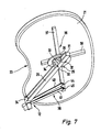
- eine perspektivische Unteransicht auf Tablar und Beschlag,
- Fig. 8
- eine perspektivische Darstellung eines zweiten Ausführungsbeispiels des erfindungsgemäßen Beschlags mit Tablar und
- Fig. 9
- eine Unteransicht auf den Beschlag mit Tablar von
Fig. 8 .
- Fig. 1
- 1 is a perspective view of a first embodiment of the fitting according to the invention or corner cabinet according to the invention, wherein the tray is in its internal position,
- Fig. 2
- a bottom view on the corner cupboard in
Fig. 1 . - Fig. 3
- a perspective view of the corner cupboard of
Fig. 1 , wherein the tray is in an intermediate position lying between the inner and the outer position, - Fig. 4
- a bottom view of the corner cabinet of
Fig. 3 .
- Fig. 5
- a perspective view of the corner cupboard of
Fig. 1 with the tray in the outward position, - Fig. 6
- a bottom view of the corner cabinet of
Fig. 5 . - Fig. 7
- a perspective bottom view on tray and fitting,
- Fig. 8
- a perspective view of a second embodiment of the fitting according to the invention with tray and
- Fig. 9
- a bottom view of the fitting with tray of
Fig. 8 ,
Die
Im Innenraum des Eckschranks 11 befindet sich wenigstens ein Tablar 21, das mittels des Beschlags 12 zwischen einer Innenstellung, in der das Tablar 21 vollständig im Innenraum 20 untergebracht ist, und einer Außenstellung, in der das Tablar 21 zumindest teilweise über eine Ebene 22 einer Türöffnung des Eckschranks 11 hinaussteht, beweglich gesteuert wird. Es ist hier beispielhaft ein einzelnes Tablar 21 dargestellt. Alternativ ist es möglich, dass im Eckschrank 11 zwei oder mehr übereinander liegende Tablare 21 angeordnet sind. Ferner ist das Tablar 21 beispielhaft in einteiliger Ausführungsform dargestellt. Es ist jedoch auch möglich, mehrteilige Tablare 21 einzusetzen.In the interior of the
Auch der Grundriss des Tablars 21 ist beispielhaft in Form einer Niere dargestellt. Das Tablar 21 besitzt an seiner der Vorderwand 18 zugewandten Innenseite eine Taillierung 23, um ein bequemes Herausschwenken aus dem Innenraum 20 bzw. Hineinschwenken in den Innenraum 20 zu ermöglichen, ohne dass das Tablar 21 an der Vorderwand 18 anstößt bzw. hängen bleibt.Also, the floor plan of the
Der Beschlag 12 besitzt wenigstens einen einerseits um eine im eingebauten Zustand des Tablars 21 ortsfeste Schwenkachse 24 schwenkbar gelagerten und andererseits an einer Lagerstelle 25 schwenkbar am zugeordneten Tablar 21 gelagerten Tragarm 26 zur Tablarabstützung. Der Tragarm 26 ist hier beispielhaft in Form eines einteiligen, starren Rohres, beispielsweise Vierkantrohrs, dargestellt.The fitting 12 has at least one pivotally mounted on the one hand to a fixed in the installed state of the
Der Beschlag 12 besitzt ferner eine Trageinrichtung 27, mit einer Tragsäule 28, die gemäß bevorzugtem Ausführungsbeispiel an der Innenseite der Vorderwand 18, insbesondere nahe der Türöffnung, befestigt ist. Zweckmäßigerweise erstreckt sich die Tragsäule 28 im Wesentlichen über die gesamte Höhe des Innenraums 20. An der Tragsäule 28 ist ein Gelenkträger 29 insbesondere höhenverstellbar befestigt, an dem sich die ortsfeste Schwenkachse 24 für den Tragarm 26 befindet.The fitting 12 further has a support means 27, with a
Dem Tragarm 26 ist ferner noch eine Führungseinrichtung 30 zugeordnet, mittels der das Tablar 21 linear beweglich am Tragarm 26 und gegenüber diesem schwenkbar gelagert ist. Wie beispielhaft in
Es ist ferner eine Antikippvorrichtung 36 vorgesehen, mit zwei über Kreuz verlaufende Stützarmen 37, 38 über die die Abstützwirkung des Tragarms 26 in Außenbereiche des Tablars 21 übertragen wird. Die Stützarme 37, 38 sind über geeignete Befestigungsmittel an der Unterseite des Tablars 21 befestigt. Zweckmäßigerweise ist das scheiben- bzw. tellerartige Kupplungselement 35 über geeignete Befestigungsmittel an den Unterseiten der Stützarme 37, 38 befestigt. Die Stützarme 37, 38 überkreuzen sich im Wesentlichen rechtwinklig und bilden zweckmäßigerweise ein einteiliges Stützkreuz. Wie insbesondere in
Der Beschlag 12 weist ferner eine Steuereinrichtung 39 auf, die zur Steuerung der Tablarbewegung zwischen der Innen- und der Außenstellung dient. Die Steuereinrichtung 39 weist einen ersten Steuer-Einzelhebel 40 und einen zweiten Steuer-Einzelhebel 41 auf, die jeweils einerseits um eine im eingebauten Zustand des Tablars 21 ortsfeste Gelenkachse 42, 43 und andererseits um eine tablarfeste Schwenkachse 44, 45 schwenkbar gelagert sind, wobei die beiden tablarfesten Schwenkachsen 44, 45 in Bezug auf die Lagerstelle 25 des Tragarms 26 an der selben Tablarseite angeordnet sind.The fitting 12 also has a
Wie insbesondere in den
Die Steuer-Einzelhebel 40, 41 besitzen jeweils einen Krümmungsabschnitt 50, der sich im Bereich der jeweiligen ortsfesten Gelenkachse 42, 43 befindet. Dadurch haben die beiden Steuer-Einzelhebel 40, 41 die Gestalt eines Hockey-Schlägers. Bevorzugterweise bestehen die beiden Steuer-Einzelhebel 40, 41 aus Flachmaterial, insbesondere Stahlblech.The control
Die beiden tablarfesten Schwenkachsen 44, 45 sind im eingebauten Zustand des Tablars 21 jeweils mit Abstand zur Lagerstelle 25 angeordnet. Die beiden tablarfesten Schwenkachsen 44, 45 liegen gemäß bevorzugtem Ausführungsbeispiel ebenfalls relativ dicht beieinander. Der Tragarm 26 teilt das Tablar 21 in dessen eingebautem Zustand in einen in der Innenstellung hinter der Ebene 22 der Türöffnung liegenden vorderen Bereich 46 und einen daneben angeordneten, in der Innenstellung im Wesentlichen hinter der Vorderwand 18 liegenden hinteren Bereich 47 auf. Die tablarfesten Schwenkachsen 44, 45 liegen hier am hinteren Bereich 47 des Tablars 21.The two tablarfesten pivot axes 44, 45 are arranged in the installed state of the
Die
Wie in den
Beim Herausschwenken des Tablars 21 läuft der Führungsschlitten 33 an den Führungsnuten 31 am Tragarm 26 entlang und zwar in Richtung auf die ortsfeste Schwenkachse 24 des Tragarms 26 zu. Gleichzeitig findet eine Schwenkbewegung des Tablars 21 an der Lagerstelle 25 von unten gesehen in Gegen-Uhrzeiger-Richtung statt. Die beiden Steuer-Einzelhebel 40, 41 steuern das Tablar 21 derart, dass es aus der Ebene 22 der Türöffnung herausschwenkt ohne dabei die Schrankperipherie zu berühren. Dabei gewährleistet die Taillierung 23 des Tablars 21, dass dieses an der Trageinrichtung 27 samt Tragsäule 28 vorbeikommt.When swinging out of the
Das Tablar 21 erreicht also die in
Schließlich erreicht das Tablar 21 die in
Beim zweiten Ausführungsbeispiel verläuft die Tablarverschwenkung in nahezu identischer Weise ab, mit dem Unterschied, dass das Tablar 21 nicht linear am Tragarm 26 geführt ist, sondern durch das Einknicken der beiden Tragarmteile 56, 57 zunächst eine Annäherung der Lagerstelle 25 an die ortsfeste Schwenkachse 24 stattfindet, wobei dann in Richtung Außenstellung des Tablars 21 wieder ein Ausknicken und somit eine Entfernung von Lagerstelle 25 und ortsfester Schwenkachse 24 stattfindet.In the second embodiment, the Tablarverschwenkung runs in almost identical manner, with the difference that the
Claims (15)
Priority Applications (3)
| Application Number | Priority Date | Filing Date | Title |
|---|---|---|---|
| EP08003326A EP2092850B1 (en) | 2008-02-23 | 2008-02-23 | Fitting for a corner cupboard |
| DE502008001383T DE502008001383D1 (en) | 2008-02-23 | 2008-02-23 | Hardware for a corner cabinet |
| AT08003326T ATE481896T1 (en) | 2008-02-23 | 2008-02-23 | FITTING FOR A CORNER CABINET |
Applications Claiming Priority (1)
| Application Number | Priority Date | Filing Date | Title |
|---|---|---|---|
| EP08003326A EP2092850B1 (en) | 2008-02-23 | 2008-02-23 | Fitting for a corner cupboard |
Publications (2)
| Publication Number | Publication Date |
|---|---|
| EP2092850A1 true EP2092850A1 (en) | 2009-08-26 |
| EP2092850B1 EP2092850B1 (en) | 2010-09-22 |
Family
ID=39462051
Family Applications (1)
| Application Number | Title | Priority Date | Filing Date |
|---|---|---|---|
| EP08003326A Expired - Fee Related EP2092850B1 (en) | 2008-02-23 | 2008-02-23 | Fitting for a corner cupboard |
Country Status (3)
| Country | Link |
|---|---|
| EP (1) | EP2092850B1 (en) |
| AT (1) | ATE481896T1 (en) |
| DE (1) | DE502008001383D1 (en) |
Cited By (11)
| Publication number | Priority date | Publication date | Assignee | Title |
|---|---|---|---|---|
| ITMC20090050A1 (en) * | 2009-03-17 | 2010-09-18 | Sige S P A | MOBILE WITH EXTRACTABLE SHELF. |
| EP2353436A1 (en) | 2010-02-05 | 2011-08-10 | Hetal-Werke Franz Hettich GmbH & Co. | Fitting for a corner cupboard and corner cupboard |
| US20110193455A1 (en) * | 2010-02-05 | 2011-08-11 | Heinrich J. Kesseböhmer KG | Fitting for a Corner Cabinet |
| AT12067U3 (en) * | 2008-10-09 | 2012-05-15 | Vibo S P A | DEVICE FOR MOVING AND SUPPORTING ELEMENTS OF A FURNITURE UNIT |
| EP2174568B1 (en) * | 2008-10-09 | 2014-04-09 | VIBO S.p.A. | Device for the movement and support of elements of a furniture unit |
| US20140225492A1 (en) * | 2011-05-23 | 2014-08-14 | Kesseböhmer Holding e.K. | Fitting for corner cabinets and pull-in device for said type of fitting |
| EP3087866A1 (en) * | 2015-04-30 | 2016-11-02 | Vauth-Sagel Holding GmbH & Co. KG | Fitting for a corner cupboard and corner cupboard with fitting |
| EP3403528A1 (en) * | 2017-05-15 | 2018-11-21 | Pelly Components AB | Storage carousel |
| IT201700069780A1 (en) * | 2017-06-22 | 2018-12-22 | Inoxa Srl | CUPBOARD WITH REMOVABLE SHELVES AND RELATED EXTRACTOR MECHANISM |
| WO2019069339A1 (en) * | 2017-10-06 | 2019-04-11 | Inoxa Srl | Cabinet with pull-out shelves and related pull-out mechanism with improved guide |
| DE202019100837U1 (en) * | 2019-02-14 | 2020-05-18 | Ninkaplast Gmbh | Cupboard with pull-out shelf |
Citations (4)
| Publication number | Priority date | Publication date | Assignee | Title |
|---|---|---|---|---|
| DE202004011200U1 (en) | 2004-07-16 | 2005-12-01 | Heinrich J. Kesseböhmer KG | Corner cupboard, especially kitchen corner cupboard |
| EP1776899A1 (en) * | 2005-10-20 | 2007-04-25 | Vauth-Sagel Holding GmbH & Co. KG | Swivel drawer from a corner cupboard |
| DE102007009894B3 (en) | 2007-03-01 | 2008-02-07 | Hetal-Werke Franz Hettich Gmbh & Co. Kg | Corner cupboard for kitchen has carrier device with decoupling devices by which tray can be uncoupled from door at set intermediate point |
| EP1925239A1 (en) * | 2006-11-27 | 2008-05-28 | Hetal-Werke Franz Hettich GmbH & Co. KG | Fitting for a corner cupboard and corner cupboard |
-
2008
- 2008-02-23 DE DE502008001383T patent/DE502008001383D1/en active Active
- 2008-02-23 EP EP08003326A patent/EP2092850B1/en not_active Expired - Fee Related
- 2008-02-23 AT AT08003326T patent/ATE481896T1/en active
Patent Citations (5)
| Publication number | Priority date | Publication date | Assignee | Title |
|---|---|---|---|---|
| DE202004011200U1 (en) | 2004-07-16 | 2005-12-01 | Heinrich J. Kesseböhmer KG | Corner cupboard, especially kitchen corner cupboard |
| EP1616503A2 (en) * | 2004-07-16 | 2006-01-18 | Heinrich J. Kesseböhmer KG | Corner cupboard, in particular kitchen corner cupboard |
| EP1776899A1 (en) * | 2005-10-20 | 2007-04-25 | Vauth-Sagel Holding GmbH & Co. KG | Swivel drawer from a corner cupboard |
| EP1925239A1 (en) * | 2006-11-27 | 2008-05-28 | Hetal-Werke Franz Hettich GmbH & Co. KG | Fitting for a corner cupboard and corner cupboard |
| DE102007009894B3 (en) | 2007-03-01 | 2008-02-07 | Hetal-Werke Franz Hettich Gmbh & Co. Kg | Corner cupboard for kitchen has carrier device with decoupling devices by which tray can be uncoupled from door at set intermediate point |
Cited By (23)
| Publication number | Priority date | Publication date | Assignee | Title |
|---|---|---|---|---|
| AT12067U3 (en) * | 2008-10-09 | 2012-05-15 | Vibo S P A | DEVICE FOR MOVING AND SUPPORTING ELEMENTS OF A FURNITURE UNIT |
| EP2174568B1 (en) * | 2008-10-09 | 2014-04-09 | VIBO S.p.A. | Device for the movement and support of elements of a furniture unit |
| ITMC20090050A1 (en) * | 2009-03-17 | 2010-09-18 | Sige S P A | MOBILE WITH EXTRACTABLE SHELF. |
| EP2229845A1 (en) * | 2009-03-17 | 2010-09-22 | Sige S.P.A. | Cabinet with pull-out shelf |
| EP2353436A1 (en) | 2010-02-05 | 2011-08-10 | Hetal-Werke Franz Hettich GmbH & Co. | Fitting for a corner cupboard and corner cupboard |
| US20110193455A1 (en) * | 2010-02-05 | 2011-08-11 | Heinrich J. Kesseböhmer KG | Fitting for a Corner Cabinet |
| US20120049708A1 (en) * | 2010-02-05 | 2012-03-01 | Hetal-Werke Franz Hettich Gmbh & Co. Kg | Fitting for a Corner Cupboard and a Corner Cupboard |
| US8911035B2 (en) | 2010-02-05 | 2014-12-16 | Hetal-Werke Franz Hettich Gmbh & Co. Kg | Fitting for a corner cupboard and a corner cupboard |
| US20140225492A1 (en) * | 2011-05-23 | 2014-08-14 | Kesseböhmer Holding e.K. | Fitting for corner cabinets and pull-in device for said type of fitting |
| US9119470B2 (en) * | 2011-05-23 | 2015-09-01 | Kesseböhmer Holding e.K. | Fitting for corner cabinets and pull-in device for said type of fitting |
| EP3087866A1 (en) * | 2015-04-30 | 2016-11-02 | Vauth-Sagel Holding GmbH & Co. KG | Fitting for a corner cupboard and corner cupboard with fitting |
| WO2016173894A1 (en) * | 2015-04-30 | 2016-11-03 | Vauth-Sagel Holding Gmbh & Co. Kg | Fitting for a corner cupboard, and corner cupboard with fitting |
| US10092094B2 (en) | 2015-04-30 | 2018-10-09 | Vauth-Sagel Holding Gmbh & Co. Kg | Fitting for a corner cupboard and corner cupboard with fitting |
| EP3403528A1 (en) * | 2017-05-15 | 2018-11-21 | Pelly Components AB | Storage carousel |
| IT201700069780A1 (en) * | 2017-06-22 | 2018-12-22 | Inoxa Srl | CUPBOARD WITH REMOVABLE SHELVES AND RELATED EXTRACTOR MECHANISM |
| WO2018235116A1 (en) * | 2017-06-22 | 2018-12-27 | Inoxa Srl | Cabinet with pull-out shelves and related pull-out mechanism |
| EA037118B1 (en) * | 2017-06-22 | 2021-02-09 | Инокса Срл | Cabinet with pull-out shelves and related pull-out mechanism |
| US11197545B2 (en) * | 2017-06-22 | 2021-12-14 | Inoxa Srl | Cabinet with pull-out shelves and related pull-out mechanism |
| WO2019069339A1 (en) * | 2017-10-06 | 2019-04-11 | Inoxa Srl | Cabinet with pull-out shelves and related pull-out mechanism with improved guide |
| CN111315259A (en) * | 2017-10-06 | 2020-06-19 | Inoxa股份责任有限公司 | Cabinet with pull-out carriage and associated pull-out mechanism with improved guide |
| EA039197B1 (en) * | 2017-10-06 | 2021-12-16 | Инокса Срл | Cabinet with pull-out shelves and related pull-out mechanism with improved guide |
| US11304517B2 (en) | 2017-10-06 | 2022-04-19 | Inoxa Srl | Cabinet with pull-out shelves and related pull-out mechanism with improved guide |
| DE202019100837U1 (en) * | 2019-02-14 | 2020-05-18 | Ninkaplast Gmbh | Cupboard with pull-out shelf |
Also Published As
| Publication number | Publication date |
|---|---|
| EP2092850B1 (en) | 2010-09-22 |
| ATE481896T1 (en) | 2010-10-15 |
| DE502008001383D1 (en) | 2010-11-04 |
Similar Documents
| Publication | Publication Date | Title |
|---|---|---|
| EP2092850B1 (en) | Fitting for a corner cupboard | |
| EP1616503B1 (en) | Corner cupboard, in particular kitchen corner cupboard | |
| EP1971245B1 (en) | Permanent-contact mechanism | |
| EP3087866B1 (en) | Fitting for a corner cupboard and corner cupboard with fitting | |
| WO2009127335A1 (en) | Furniture hinge | |
| EP2713816B1 (en) | Fitting for corner cabinets | |
| DE102006007702A1 (en) | Fitting device for a furniture flap | |
| DE102008056475B3 (en) | Center arm for accommodating contact grilling- or roasting upper plate of contact grilling- or roasting device, has adjusting device with control profile element that has profile for sliding element axial movement in longitudinal direction | |
| EP1964490B1 (en) | Corner unit, in particular kitchen corner unit | |
| DE102006055807A1 (en) | Fitting for a corner cupboard and corner cupboard | |
| EP2353438A2 (en) | Fitting for corner cupboards | |
| WO2016177559A1 (en) | Furniture hinge comprising a damper | |
| WO2016131778A1 (en) | Sliding/pivoting mechanism of a shelf of a piece of furniture, and piece of furniture | |
| EP3854263A1 (en) | Armrest, in particular for an office chair | |
| EP2064971A1 (en) | Fitting for a corner cupboard | |
| DE202010003833U1 (en) | hinge | |
| DE10203269A1 (en) | Flap has a lever (8) with a force transfer unit (19)with an adjustable lever arm and gas pressure spring (7) with actuating part (9) so that the angle under the gas pressure spring | |
| EP3090654B1 (en) | Swivel device for a tray holder on a corner cabinet unit | |
| DE202010002230U1 (en) | Fitting for a corner cupboard and corner cupboard | |
| EP1126114B1 (en) | Adjustable hinge | |
| DE202010002232U1 (en) | Fitting arrangement for a corner cabinet | |
| EP2191745B1 (en) | Fitting for a corner cupboard | |
| DE19738931C1 (en) | Hinge for container covers and esp for kitchen furniture | |
| EP0457247B1 (en) | Transport trolley for operating tables | |
| DE1559897C2 (en) | Furniture hinge with a swivel angle of 170 to 180 ° |
Legal Events
| Date | Code | Title | Description |
|---|---|---|---|
| PUAI | Public reference made under article 153(3) epc to a published international application that has entered the european phase |
Free format text: ORIGINAL CODE: 0009012 |
|
| 17P | Request for examination filed |
Effective date: 20080820 |
|
| AK | Designated contracting states |
Kind code of ref document: A1 Designated state(s): AT BE BG CH CY CZ DE DK EE ES FI FR GB GR HR HU IE IS IT LI LT LU LV MC MT NL NO PL PT RO SE SI SK TR |
|
| AX | Request for extension of the european patent |
Extension state: AL BA MK RS |
|
| GRAP | Despatch of communication of intention to grant a patent |
Free format text: ORIGINAL CODE: EPIDOSNIGR1 |
|
| AKX | Designation fees paid |
Designated state(s): AT DE FR IT |
|
| GRAS | Grant fee paid |
Free format text: ORIGINAL CODE: EPIDOSNIGR3 |
|
| GRAA | (expected) grant |
Free format text: ORIGINAL CODE: 0009210 |
|
| AK | Designated contracting states |
Kind code of ref document: B1 Designated state(s): AT DE FR IT |
|
| REF | Corresponds to: |
Ref document number: 502008001383 Country of ref document: DE Date of ref document: 20101104 Kind code of ref document: P |
|
| PLBE | No opposition filed within time limit |
Free format text: ORIGINAL CODE: 0009261 |
|
| STAA | Information on the status of an ep patent application or granted ep patent |
Free format text: STATUS: NO OPPOSITION FILED WITHIN TIME LIMIT |
|
| 26N | No opposition filed |
Effective date: 20110623 |
|
| REG | Reference to a national code |
Ref country code: DE Ref legal event code: R097 Ref document number: 502008001383 Country of ref document: DE Effective date: 20110623 |
|
| PGFP | Annual fee paid to national office [announced via postgrant information from national office to epo] |
Ref country code: AT Payment date: 20140212 Year of fee payment: 7 Ref country code: FR Payment date: 20140219 Year of fee payment: 7 |
|
| PGFP | Annual fee paid to national office [announced via postgrant information from national office to epo] |
Ref country code: DE Payment date: 20150219 Year of fee payment: 8 Ref country code: IT Payment date: 20150226 Year of fee payment: 8 |
|
| REG | Reference to a national code |
Ref country code: AT Ref legal event code: MM01 Ref document number: 481896 Country of ref document: AT Kind code of ref document: T Effective date: 20150223 |
|
| REG | Reference to a national code |
Ref country code: FR Ref legal event code: ST Effective date: 20151030 |
|
| PG25 | Lapsed in a contracting state [announced via postgrant information from national office to epo] |
Ref country code: AT Free format text: LAPSE BECAUSE OF NON-PAYMENT OF DUE FEES Effective date: 20150223 |
|
| PG25 | Lapsed in a contracting state [announced via postgrant information from national office to epo] |
Ref country code: FR Free format text: LAPSE BECAUSE OF NON-PAYMENT OF DUE FEES Effective date: 20150302 |
|
| REG | Reference to a national code |
Ref country code: DE Ref legal event code: R119 Ref document number: 502008001383 Country of ref document: DE |
|
| PG25 | Lapsed in a contracting state [announced via postgrant information from national office to epo] |
Ref country code: IT Free format text: LAPSE BECAUSE OF NON-PAYMENT OF DUE FEES Effective date: 20160223 |
|
| PG25 | Lapsed in a contracting state [announced via postgrant information from national office to epo] |
Ref country code: DE Free format text: LAPSE BECAUSE OF NON-PAYMENT OF DUE FEES Effective date: 20160901 |