EP2090858B1 - Wärmetauscher - Google Patents
Wärmetauscher Download PDFInfo
- Publication number
- EP2090858B1 EP2090858B1 EP09001426A EP09001426A EP2090858B1 EP 2090858 B1 EP2090858 B1 EP 2090858B1 EP 09001426 A EP09001426 A EP 09001426A EP 09001426 A EP09001426 A EP 09001426A EP 2090858 B1 EP2090858 B1 EP 2090858B1
- Authority
- EP
- European Patent Office
- Prior art keywords
- coil
- heat exchanger
- section
- cross
- ventilation
- Prior art date
- Legal status (The legal status is an assumption and is not a legal conclusion. Google has not performed a legal analysis and makes no representation as to the accuracy of the status listed.)
- Active
Links
Images
Classifications
-
- F—MECHANICAL ENGINEERING; LIGHTING; HEATING; WEAPONS; BLASTING
- F28—HEAT EXCHANGE IN GENERAL
- F28D—HEAT-EXCHANGE APPARATUS, NOT PROVIDED FOR IN ANOTHER SUBCLASS, IN WHICH THE HEAT-EXCHANGE MEDIA DO NOT COME INTO DIRECT CONTACT
- F28D1/00—Heat-exchange apparatus having stationary conduit assemblies for one heat-exchange medium only, the media being in contact with different sides of the conduit wall, in which the other heat-exchange medium is a large body of fluid, e.g. domestic or motor car radiators
- F28D1/02—Heat-exchange apparatus having stationary conduit assemblies for one heat-exchange medium only, the media being in contact with different sides of the conduit wall, in which the other heat-exchange medium is a large body of fluid, e.g. domestic or motor car radiators with heat-exchange conduits immersed in the body of fluid
- F28D1/04—Heat-exchange apparatus having stationary conduit assemblies for one heat-exchange medium only, the media being in contact with different sides of the conduit wall, in which the other heat-exchange medium is a large body of fluid, e.g. domestic or motor car radiators with heat-exchange conduits immersed in the body of fluid with tubular conduits
- F28D1/047—Heat-exchange apparatus having stationary conduit assemblies for one heat-exchange medium only, the media being in contact with different sides of the conduit wall, in which the other heat-exchange medium is a large body of fluid, e.g. domestic or motor car radiators with heat-exchange conduits immersed in the body of fluid with tubular conduits the conduits being bent, e.g. in a serpentine or zig-zag
- F28D1/0472—Heat-exchange apparatus having stationary conduit assemblies for one heat-exchange medium only, the media being in contact with different sides of the conduit wall, in which the other heat-exchange medium is a large body of fluid, e.g. domestic or motor car radiators with heat-exchange conduits immersed in the body of fluid with tubular conduits the conduits being bent, e.g. in a serpentine or zig-zag the conduits being helically or spirally coiled
- F28D1/0473—Heat-exchange apparatus having stationary conduit assemblies for one heat-exchange medium only, the media being in contact with different sides of the conduit wall, in which the other heat-exchange medium is a large body of fluid, e.g. domestic or motor car radiators with heat-exchange conduits immersed in the body of fluid with tubular conduits the conduits being bent, e.g. in a serpentine or zig-zag the conduits being helically or spirally coiled the conduits having a non-circular cross-section
-
- F—MECHANICAL ENGINEERING; LIGHTING; HEATING; WEAPONS; BLASTING
- F28—HEAT EXCHANGE IN GENERAL
- F28D—HEAT-EXCHANGE APPARATUS, NOT PROVIDED FOR IN ANOTHER SUBCLASS, IN WHICH THE HEAT-EXCHANGE MEDIA DO NOT COME INTO DIRECT CONTACT
- F28D7/00—Heat-exchange apparatus having stationary tubular conduit assemblies for both heat-exchange media, the media being in contact with different sides of a conduit wall
- F28D7/02—Heat-exchange apparatus having stationary tubular conduit assemblies for both heat-exchange media, the media being in contact with different sides of a conduit wall the conduits being helically coiled
- F28D7/024—Heat-exchange apparatus having stationary tubular conduit assemblies for both heat-exchange media, the media being in contact with different sides of a conduit wall the conduits being helically coiled the conduits of only one medium being helically coiled tubes, the coils having a cylindrical configuration
-
- F—MECHANICAL ENGINEERING; LIGHTING; HEATING; WEAPONS; BLASTING
- F28—HEAT EXCHANGE IN GENERAL
- F28F—DETAILS OF HEAT-EXCHANGE AND HEAT-TRANSFER APPARATUS, OF GENERAL APPLICATION
- F28F2265/00—Safety or protection arrangements; Arrangements for preventing malfunction
- F28F2265/18—Safety or protection arrangements; Arrangements for preventing malfunction for removing contaminants, e.g. for degassing
Definitions
- the invention relates to a heat exchanger according to the preamble of patent claim 1.
- a heat exchanger of the type mentioned is according to the DE 200 09 560 U1 known. This consists of a liquid heat transfer medium leading, helically coiled coiled tubing with a horizontally oriented helical axis and with one above and one below the helix axis coiled tube part.
- supply and return connections are provided on the outer circumference of the coiled tubing, on the one hand serve for venting and removal of the heat transfer medium on the other hand also for venting.
- This heat exchanger is part of a boiler, ie it encloses a combustion chamber with a burner producing an exhaust gas, wherein the exhaust gas flows through flow gaps of the coiled tubing and thereby emits its heat to the liquid heat transfer medium.
- the invention has for its object to provide for a tube-like heat exchanger with horizontal helical axis for the best possible ventability, regardless of whether this heat exchanger has the above-described flow and return ports or not.
- heat exchanger of the type mentioned by the features listed in the characterizing part of patent claim 1. It should be noted that the heat exchanger according to the invention is not limited to the application in a boiler, but rather, for example, in hot water tanks can be used (in this case, the heat exchanger is not of an exhaust gas of a burner, but flows around to be heated water), where also the problem of deteriorated heat transfer can occur by gas entry.
- the coiled tubing has a two-part flow cross-section, the first, larger flow cross-section being provided for the heat transfer medium and the second, smaller flow cross-section being designed as bleeding helix, wherein this helix per helix travel is at least one in the area of the helix part located above the helical axis Having the first connected to the second flow cross-section vent opening.
- the proviso of a "two-part flow cross-section" includes both the possibility of a one-piece tube coil in principle with two flow spaces and the possibility that another component is introduced into the coiled tubing.
- an additional coiled tubing (venting coil) is arranged in the coiled tube, wherein the per vent preferably provided in the uppermost area vent allows escape of possibly accumulated air or gas.
- venting coil should be smaller cross section than the coiled tubing is on the one hand mandatory, otherwise they could not be arranged in the coiled tubing, on the other hand, this proviso but also means that especially the gas and only very small parts Heat transfer medium can flow through the vent coil. This will be discussed in more detail below.
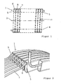
- FIG. 1 First, a highly abstracted embodiment of the heat exchanger according to the invention is shown. This exists (but this also applies to the embodiments according to FIGS. 2 to 4 ) from a liquid heat transfer medium leading, an approximately rectangular flow cross-section having coiled tubing 1 with a horizontally oriented helical axis 2 and with one above and below the helix axis 2 coiled tube part 3, 4.
- the coiled tubing is helically wound formed.
- it serves as a heat exchanger in a boiler, it has fürströmspalte 10 (indicated by dashed lines) through which flows the hot exhaust gas of a burner and thereby heats the heat transfer medium in the coiled tubing.
- the coiled tubing 1 has a two-part flow cross-section, wherein the first, larger flow cross section 5 is provided for the heat transfer medium and the second, smaller flow cross section 6 is formed as a bleed helix 7, wherein this per helical gear in the region above Has spiral axis 2 located coiled tubing part 3 at least one of the first with the second flow cross-section 5, 6 connecting the vent opening 8.
- vent openings 8 could in this case have been produced, for example, by double drilling through the coiled tubing and then welding the outer opening.
- the venting opening 8 has a cross-sectional area which is smaller than the flow-through cross section 6 of the venting spiral 7. Further, since the flow area 5 for the heat transfer medium is greater than the flow cross-section 6 of the venting coil 7, it follows that the cross-section of the vent opening 8 is preferably much smaller than the flow area 5 for the heat transfer medium. This proviso leads to a pressure gradient within the heat exchanger, so that on the one hand good ventilation is ensured, but on the other hand, only a very small loss of heat transfer medium via the vent coil results.
- the flow cross-section 6 of the venting helix 7 is circular and the vent 8 itself is formed as a circular bore.
- the venting coil 7 for example, rectangular
- the vent opening 8 for example, slit-shaped
- a tubular helix with a simple borehole or even several boreholes is (obviously) easiest to produce.
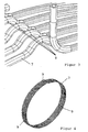
- venting coil 7 In order to ensure a secure positioning of the venting coil 7 within the coiled tubing 1, in particular with reference to FIG. 4 preferably provided that the helically wound venting coil 7 distributed over its circumference preferably three radially outwardly facing, inside of the coiled tubing 1 supporting bulges 9 has.
- the outer diameter of the venting spiral 7 defined by the bulges 9 corresponds approximately to the inner outer diameter of the flow cross section 5 for the heat transfer medium, ie after screwing in the venting coil 7, this is supported on the inner wall of the coiled tubing 1 so that the position of the venting coil 7 is within the coiled tubing 1 always remains safe, which is particularly important in relation to the position of the vent opening 8, since the venting of the heat exchanger, of course, works best when the vent 8 is located at the very top within the coiled tubing 1, and this is accordingly preferred in that one of the bulges 9 is arranged in the uppermost region of the upper coiled tubing part 3 and the vent opening 8 is arranged on the latter (cf. FIG. 2 and 3 ).
- the heat exchanger according to the invention or in particular the venting technology according to the invention functions as follows:
- the reinstallation of a boiler with a horizontally oriented heat exchanger it follows that in the heat transfer medium dissolved gas (in particular air) due to gravity accumulates at the highest point within the coiled tubing 1.
- the venting coil 7 with a vent opening 8 is arranged especially at this point, the gas can be discharged via the venting coil 7, for which purpose it is brought into contact with the environment of the heat exchanger at least temporarily (for example with a quick-vent valve).
- the pressure in the heat transfer medium ensures that excess gas is discharged via the vent 8 and the vent coil 7 from the heat exchanger and there no longer disturbs the heat transfer.
- the heat exchanger according to the invention is characterized by the screwed-in all helical or venting bleeder by an extremely efficient ventilation process, wherein This simple quick-venting can be carried out optionally at commissioning of the heat exchanger, but of course also at any time later and again and again.
- venting helix conforms to the FIG. 2 at least initially designed so that screwing is possible without hindrance.
- At least one end of the venting coil must be open during the venting process against an environment having a lower pressure level than the heat transfer medium.
Landscapes
- Engineering & Computer Science (AREA)
- Physics & Mathematics (AREA)
- Thermal Sciences (AREA)
- Mechanical Engineering (AREA)
- General Engineering & Computer Science (AREA)
- Heat-Exchange Devices With Radiators And Conduit Assemblies (AREA)
- Separation By Low-Temperature Treatments (AREA)
- Power Steering Mechanism (AREA)
- Compression-Type Refrigeration Machines With Reversible Cycles (AREA)
Priority Applications (2)
| Application Number | Priority Date | Filing Date | Title |
|---|---|---|---|
| PL09001426T PL2090858T3 (pl) | 2008-02-12 | 2009-02-03 | Wymiennik ciepła |
| SI200930002T SI2090858T1 (sl) | 2008-02-12 | 2009-02-03 | Toplotni izmenjevalnik |
Applications Claiming Priority (1)
| Application Number | Priority Date | Filing Date | Title |
|---|---|---|---|
| DE102008008734A DE102008008734A1 (de) | 2008-02-12 | 2008-02-12 | Wärmetauscher |
Publications (2)
| Publication Number | Publication Date |
|---|---|
| EP2090858A1 EP2090858A1 (de) | 2009-08-19 |
| EP2090858B1 true EP2090858B1 (de) | 2010-04-07 |
Family
ID=40467033
Family Applications (1)
| Application Number | Title | Priority Date | Filing Date |
|---|---|---|---|
| EP09001426A Active EP2090858B1 (de) | 2008-02-12 | 2009-02-03 | Wärmetauscher |
Country Status (9)
| Country | Link |
|---|---|
| EP (1) | EP2090858B1 (pl) |
| AT (1) | ATE463709T1 (pl) |
| DE (2) | DE102008008734A1 (pl) |
| DK (1) | DK2090858T3 (pl) |
| ES (1) | ES2341507T3 (pl) |
| HR (1) | HRP20100367T1 (pl) |
| PL (1) | PL2090858T3 (pl) |
| RU (1) | RU2476799C2 (pl) |
| SI (1) | SI2090858T1 (pl) |
Families Citing this family (1)
| Publication number | Priority date | Publication date | Assignee | Title |
|---|---|---|---|---|
| DE102011010444A1 (de) * | 2011-02-04 | 2012-08-09 | Viessmann Werke Gmbh & Co Kg | Heizkessel |
Family Cites Families (8)
| Publication number | Priority date | Publication date | Assignee | Title |
|---|---|---|---|---|
| SU494586A1 (ru) * | 1974-02-06 | 1975-12-05 | Ордена Трудового Красного Знамени Предприятие П/Я А-1665 | Кольцевой теплообменник |
| DE3315258A1 (de) * | 1983-04-27 | 1984-10-31 | Etablissement Agura, Vaduz | Spiralringheizkessel |
| FR2550615B1 (fr) * | 1983-08-12 | 1985-12-06 | Fonderie Soc Gen De | Chaudiere a echangeur en serpentin |
| RU2080536C1 (ru) * | 1994-01-12 | 1997-05-27 | Тамбовское акционерное общество открытого типа "Комсомолец" | Теплообменник |
| DE20009560U1 (de) | 2000-05-27 | 2000-09-28 | Viessmann Werke GmbH & Co., 35108 Allendorf | Wärmetauscher |
| DE10106371A1 (de) * | 2001-02-12 | 2002-08-14 | Ludwig Pilsl | Vorrichtung für den Austausch von Wärme |
| DE102004005048A1 (de) | 2004-01-30 | 2005-09-01 | Viessmann Werke Gmbh & Co Kg | Heizgerät |
| US7685839B2 (en) * | 2004-07-09 | 2010-03-30 | Junjie Gu | Refrigeration system |
-
2008
- 2008-02-12 DE DE102008008734A patent/DE102008008734A1/de not_active Withdrawn
-
2009
- 2009-01-20 RU RU2009101457/06A patent/RU2476799C2/ru not_active IP Right Cessation
- 2009-02-03 AT AT09001426T patent/ATE463709T1/de active
- 2009-02-03 DE DE502009000007T patent/DE502009000007D1/de active Active
- 2009-02-03 ES ES09001426T patent/ES2341507T3/es active Active
- 2009-02-03 PL PL09001426T patent/PL2090858T3/pl unknown
- 2009-02-03 SI SI200930002T patent/SI2090858T1/sl unknown
- 2009-02-03 DK DK09001426.7T patent/DK2090858T3/da active
- 2009-02-03 EP EP09001426A patent/EP2090858B1/de active Active
-
2010
- 2010-06-29 HR HR20100367T patent/HRP20100367T1/hr unknown
Also Published As
| Publication number | Publication date |
|---|---|
| RU2009101457A (ru) | 2010-07-27 |
| DK2090858T3 (da) | 2010-07-05 |
| SI2090858T1 (sl) | 2010-07-30 |
| DE502009000007D1 (de) | 2010-05-20 |
| PL2090858T3 (pl) | 2010-07-30 |
| ES2341507T3 (es) | 2010-06-21 |
| DE102008008734A1 (de) | 2009-08-13 |
| RU2476799C2 (ru) | 2013-02-27 |
| EP2090858A1 (de) | 2009-08-19 |
| HRP20100367T1 (hr) | 2010-10-31 |
| ATE463709T1 (de) | 2010-04-15 |
Similar Documents
| Publication | Publication Date | Title |
|---|---|---|
| EP1760279A2 (de) | Schalldämpfer für eine Abgasanlage | |
| EP4141321B1 (de) | Gasbrennervorrichtung mit flammensperreinrichtung | |
| DE19912572C2 (de) | Kompaktheizkessel, insbesondere zur Verwendung als Brennwertheizkessel | |
| EP3400155A2 (de) | Geräuschdämpfer für ein druckluftsystem eines fahrzeugs, insbesondere eines nutzfahrzeugs | |
| DE102013200177A1 (de) | Dämpfungseinrichtung in einer hydraulischen Strecke | |
| DE102015104180A1 (de) | Vorrichtung für einen Wärmeübertrager zum Sammeln und Verteilen eines Wärmeträgerfluids | |
| EP2090858B1 (de) | Wärmetauscher | |
| WO2007079730A1 (de) | Heizkessel | |
| DE102011115050A1 (de) | Stützstruktur für ein Filterelement | |
| EP2705268B1 (de) | Hydraulische strecke mit einer entlüftungseinrichtung | |
| EP2538158B1 (de) | Kühl- und gefriergerät | |
| EP2306112A1 (de) | Heizgerät | |
| DE10300384B4 (de) | Abgasanlage | |
| DE2541216C3 (pl) | ||
| DE102007009433A1 (de) | Lüftungsbaustein und/oder Vorrichtung zum Verschließen einer Öffnung in einer Wand oder Decke | |
| EP1277014A1 (de) | Dampfinjektor | |
| DE102015111512A1 (de) | Schalldämpfer | |
| DE3017857C2 (de) | Hahn mit Dämpfungsvorrichtung | |
| DE102011016565A1 (de) | Heat Exchanger and Method of Manufacturing such a Heat Exchanger | |
| DE29824167U1 (de) | Rauchgasabzugsschalldämpfer | |
| DE102008037904B4 (de) | Akkumulator | |
| DE102009011151A1 (de) | Gliederheizkörpertrennelement und Gliederheizkörper | |
| DE102017113076A1 (de) | Warmwasserspeicher | |
| DE102004040583A1 (de) | Schalldämpfer insbesondere für die Abgasanlage eines Kraftfahrzeugs | |
| EP3145655B1 (de) | Vorrichtung in form einer kolbeneinheit und verfahren zu deren betrieb |
Legal Events
| Date | Code | Title | Description |
|---|---|---|---|
| PUAI | Public reference made under article 153(3) epc to a published international application that has entered the european phase |
Free format text: ORIGINAL CODE: 0009012 |
|
| AK | Designated contracting states |
Kind code of ref document: A1 Designated state(s): AT BE BG CH CY CZ DE DK EE ES FI FR GB GR HR HU IE IS IT LI LT LU LV MC MK MT NL NO PL PT RO SE SI SK TR |
|
| AX | Request for extension of the european patent |
Extension state: AL BA RS |
|
| 17P | Request for examination filed |
Effective date: 20091009 |
|
| GRAP | Despatch of communication of intention to grant a patent |
Free format text: ORIGINAL CODE: EPIDOSNIGR1 |
|
| GRAS | Grant fee paid |
Free format text: ORIGINAL CODE: EPIDOSNIGR3 |
|
| GRAA | (expected) grant |
Free format text: ORIGINAL CODE: 0009210 |
|
| AK | Designated contracting states |
Kind code of ref document: B1 Designated state(s): AT BE BG CH CY CZ DE DK EE ES FI FR GB GR HR HU IE IS IT LI LT LU LV MC MK MT NL NO PL PT RO SE SI SK TR |
|
| REG | Reference to a national code |
Ref country code: GB Ref legal event code: FG4D Free format text: NOT ENGLISH |
|
| REG | Reference to a national code |
Ref country code: CH Ref legal event code: EP |
|
| AKX | Designation fees paid |
Designated state(s): AT BE BG CH CY CZ DE DK EE ES FI FR GB GR HR HU IE IS IT LI LT LU LV MC MK MT NL NO PL PT RO SE SI SK TR |
|
| REG | Reference to a national code |
Ref country code: IE Ref legal event code: FG4D Free format text: LANGUAGE OF EP DOCUMENT: GERMAN |
|
| REG | Reference to a national code |
Ref country code: CH Ref legal event code: NV Representative=s name: PATENTANWALTSBUERO DR. URS FALK |
|
| REF | Corresponds to: |
Ref document number: 502009000007 Country of ref document: DE Date of ref document: 20100520 Kind code of ref document: P |
|
| REG | Reference to a national code |
Ref country code: SE Ref legal event code: TRGR |
|
| REG | Reference to a national code |
Ref country code: RO Ref legal event code: EPE |
|
| REG | Reference to a national code |
Ref country code: ES Ref legal event code: FG2A Ref document number: 2341507 Country of ref document: ES Kind code of ref document: T3 |
|
| REG | Reference to a national code |
Ref country code: NL Ref legal event code: T3 |
|
| REG | Reference to a national code |
Ref country code: HR Ref legal event code: TUEP Ref document number: P20100367 Country of ref document: HR |
|
| REG | Reference to a national code |
Ref country code: DK Ref legal event code: T3 |
|
| REG | Reference to a national code |
Ref country code: PL Ref legal event code: T3 |
|
| REG | Reference to a national code |
Ref country code: IE Ref legal event code: FD4D |
|
| PG25 | Lapsed in a contracting state [announced via postgrant information from national office to epo] |
Ref country code: NO Free format text: LAPSE BECAUSE OF FAILURE TO SUBMIT A TRANSLATION OF THE DESCRIPTION OR TO PAY THE FEE WITHIN THE PRESCRIBED TIME-LIMIT Effective date: 20100707 |
|
| REG | Reference to a national code |
Ref country code: HR Ref legal event code: T1PR Ref document number: P20100367 Country of ref document: HR |
|
| REG | Reference to a national code |
Ref country code: SK Ref legal event code: T3 Ref document number: E 7780 Country of ref document: SK |
|
| PG25 | Lapsed in a contracting state [announced via postgrant information from national office to epo] |
Ref country code: IS Free format text: LAPSE BECAUSE OF FAILURE TO SUBMIT A TRANSLATION OF THE DESCRIPTION OR TO PAY THE FEE WITHIN THE PRESCRIBED TIME-LIMIT Effective date: 20100807 Ref country code: FI Free format text: LAPSE BECAUSE OF FAILURE TO SUBMIT A TRANSLATION OF THE DESCRIPTION OR TO PAY THE FEE WITHIN THE PRESCRIBED TIME-LIMIT Effective date: 20100407 |
|
| REG | Reference to a national code |
Ref country code: HU Ref legal event code: AG4A Ref document number: E008396 Country of ref document: HU |
|
| PG25 | Lapsed in a contracting state [announced via postgrant information from national office to epo] |
Ref country code: CY Free format text: LAPSE BECAUSE OF FAILURE TO SUBMIT A TRANSLATION OF THE DESCRIPTION OR TO PAY THE FEE WITHIN THE PRESCRIBED TIME-LIMIT Effective date: 20100616 |
|
| REG | Reference to a national code |
Ref country code: HR Ref legal event code: ODRP Ref document number: P20100367 Country of ref document: HR Payment date: 20110128 Year of fee payment: 3 |
|
| PG25 | Lapsed in a contracting state [announced via postgrant information from national office to epo] |
Ref country code: IE Free format text: LAPSE BECAUSE OF FAILURE TO SUBMIT A TRANSLATION OF THE DESCRIPTION OR TO PAY THE FEE WITHIN THE PRESCRIBED TIME-LIMIT Effective date: 20100407 Ref country code: EE Free format text: LAPSE BECAUSE OF FAILURE TO SUBMIT A TRANSLATION OF THE DESCRIPTION OR TO PAY THE FEE WITHIN THE PRESCRIBED TIME-LIMIT Effective date: 20100407 |
|
| PLBE | No opposition filed within time limit |
Free format text: ORIGINAL CODE: 0009261 |
|
| STAA | Information on the status of an ep patent application or granted ep patent |
Free format text: STATUS: NO OPPOSITION FILED WITHIN TIME LIMIT |
|
| 26N | No opposition filed |
Effective date: 20110110 |
|
| PGFP | Annual fee paid to national office [announced via postgrant information from national office to epo] |
Ref country code: HU Payment date: 20110207 Year of fee payment: 3 Ref country code: DK Payment date: 20110224 Year of fee payment: 3 |
|
| PG25 | Lapsed in a contracting state [announced via postgrant information from national office to epo] |
Ref country code: GR Free format text: LAPSE BECAUSE OF FAILURE TO SUBMIT A TRANSLATION OF THE DESCRIPTION OR TO PAY THE FEE WITHIN THE PRESCRIBED TIME-LIMIT Effective date: 20100708 |
|
| PGFP | Annual fee paid to national office [announced via postgrant information from national office to epo] |
Ref country code: SI Payment date: 20110126 Year of fee payment: 3 Ref country code: SK Payment date: 20110128 Year of fee payment: 3 Ref country code: SE Payment date: 20110126 Year of fee payment: 3 Ref country code: RO Payment date: 20110126 Year of fee payment: 3 Ref country code: HR Payment date: 20110128 Year of fee payment: 3 Ref country code: LV Payment date: 20110202 Year of fee payment: 3 |
|
| PGFP | Annual fee paid to national office [announced via postgrant information from national office to epo] |
Ref country code: ES Payment date: 20110131 Year of fee payment: 3 |
|
| PG25 | Lapsed in a contracting state [announced via postgrant information from national office to epo] |
Ref country code: MC Free format text: LAPSE BECAUSE OF NON-PAYMENT OF DUE FEES Effective date: 20110228 |
|
| PG25 | Lapsed in a contracting state [announced via postgrant information from national office to epo] |
Ref country code: MT Free format text: LAPSE BECAUSE OF FAILURE TO SUBMIT A TRANSLATION OF THE DESCRIPTION OR TO PAY THE FEE WITHIN THE PRESCRIBED TIME-LIMIT Effective date: 20100407 |
|
| REG | Reference to a national code |
Ref country code: HR Ref legal event code: PBON Ref document number: P20100367 Country of ref document: HR Effective date: 20120304 |
|
| REG | Reference to a national code |
Ref country code: NL Ref legal event code: V1 Effective date: 20120901 |
|
| PG25 | Lapsed in a contracting state [announced via postgrant information from national office to epo] |
Ref country code: SE Free format text: LAPSE BECAUSE OF NON-PAYMENT OF DUE FEES Effective date: 20120204 |
|
| REG | Reference to a national code |
Ref country code: SK Ref legal event code: MM4A Ref document number: E 7780 Country of ref document: SK Effective date: 20120203 |
|
| REG | Reference to a national code |
Ref country code: DK Ref legal event code: EBP |
|
| PG25 | Lapsed in a contracting state [announced via postgrant information from national office to epo] |
Ref country code: LV Free format text: LAPSE BECAUSE OF NON-PAYMENT OF DUE FEES Effective date: 20120203 Ref country code: HR Free format text: LAPSE BECAUSE OF NON-PAYMENT OF DUE FEES Effective date: 20120304 Ref country code: SK Free format text: LAPSE BECAUSE OF NON-PAYMENT OF DUE FEES Effective date: 20120203 |
|
| PG25 | Lapsed in a contracting state [announced via postgrant information from national office to epo] |
Ref country code: HU Free format text: LAPSE BECAUSE OF NON-PAYMENT OF DUE FEES Effective date: 20120204 Ref country code: NL Free format text: LAPSE BECAUSE OF NON-PAYMENT OF DUE FEES Effective date: 20120901 |
|
| REG | Reference to a national code |
Ref country code: SI Ref legal event code: KO00 Effective date: 20121204 |
|
| PG25 | Lapsed in a contracting state [announced via postgrant information from national office to epo] |
Ref country code: SI Free format text: LAPSE BECAUSE OF NON-PAYMENT OF DUE FEES Effective date: 20120204 |
|
| PG25 | Lapsed in a contracting state [announced via postgrant information from national office to epo] |
Ref country code: LU Free format text: LAPSE BECAUSE OF NON-PAYMENT OF DUE FEES Effective date: 20110203 |
|
| PG25 | Lapsed in a contracting state [announced via postgrant information from national office to epo] |
Ref country code: PT Free format text: LAPSE BECAUSE OF NON-PAYMENT OF DUE FEES Effective date: 20100407 |
|
| PG25 | Lapsed in a contracting state [announced via postgrant information from national office to epo] |
Ref country code: RO Free format text: LAPSE BECAUSE OF NON-PAYMENT OF DUE FEES Effective date: 20120203 |
|
| PG25 | Lapsed in a contracting state [announced via postgrant information from national office to epo] |
Ref country code: BG Free format text: LAPSE BECAUSE OF FAILURE TO SUBMIT A TRANSLATION OF THE DESCRIPTION OR TO PAY THE FEE WITHIN THE PRESCRIBED TIME-LIMIT Effective date: 20100707 |
|
| REG | Reference to a national code |
Ref country code: ES Ref legal event code: FD2A Effective date: 20131018 |
|
| PG25 | Lapsed in a contracting state [announced via postgrant information from national office to epo] |
Ref country code: ES Free format text: LAPSE BECAUSE OF NON-PAYMENT OF DUE FEES Effective date: 20120204 Ref country code: DK Free format text: LAPSE BECAUSE OF NON-PAYMENT OF DUE FEES Effective date: 20120229 |
|
| REG | Reference to a national code |
Ref country code: FR Ref legal event code: PLFP Year of fee payment: 7 |
|
| PGFP | Annual fee paid to national office [announced via postgrant information from national office to epo] |
Ref country code: CH Payment date: 20150223 Year of fee payment: 7 Ref country code: CZ Payment date: 20150127 Year of fee payment: 7 Ref country code: DE Payment date: 20150126 Year of fee payment: 7 Ref country code: LT Payment date: 20150127 Year of fee payment: 7 |
|
| PGFP | Annual fee paid to national office [announced via postgrant information from national office to epo] |
Ref country code: PL Payment date: 20150126 Year of fee payment: 7 Ref country code: GB Payment date: 20150219 Year of fee payment: 7 Ref country code: FR Payment date: 20150302 Year of fee payment: 7 Ref country code: TR Payment date: 20150128 Year of fee payment: 7 Ref country code: AT Payment date: 20150224 Year of fee payment: 7 |
|
| PGFP | Annual fee paid to national office [announced via postgrant information from national office to epo] |
Ref country code: BE Payment date: 20150129 Year of fee payment: 7 |
|
| PGFP | Annual fee paid to national office [announced via postgrant information from national office to epo] |
Ref country code: IT Payment date: 20160219 Year of fee payment: 8 |
|
| PG25 | Lapsed in a contracting state [announced via postgrant information from national office to epo] |
Ref country code: BE Free format text: LAPSE BECAUSE OF NON-PAYMENT OF DUE FEES Effective date: 20160229 |
|
| REG | Reference to a national code |
Ref country code: LT Ref legal event code: MM4D Effective date: 20160203 |
|
| REG | Reference to a national code |
Ref country code: DE Ref legal event code: R119 Ref document number: 502009000007 Country of ref document: DE |
|
| REG | Reference to a national code |
Ref country code: CH Ref legal event code: PL |
|
| REG | Reference to a national code |
Ref country code: AT Ref legal event code: MM01 Ref document number: 463709 Country of ref document: AT Kind code of ref document: T Effective date: 20160203 |
|
| GBPC | Gb: european patent ceased through non-payment of renewal fee |
Effective date: 20160203 |
|
| PG25 | Lapsed in a contracting state [announced via postgrant information from national office to epo] |
Ref country code: CH Free format text: LAPSE BECAUSE OF NON-PAYMENT OF DUE FEES Effective date: 20160229 Ref country code: LT Free format text: LAPSE BECAUSE OF NON-PAYMENT OF DUE FEES Effective date: 20160203 Ref country code: LI Free format text: LAPSE BECAUSE OF NON-PAYMENT OF DUE FEES Effective date: 20160229 |
|
| REG | Reference to a national code |
Ref country code: FR Ref legal event code: ST Effective date: 20161028 |
|
| PG25 | Lapsed in a contracting state [announced via postgrant information from national office to epo] |
Ref country code: AT Free format text: LAPSE BECAUSE OF NON-PAYMENT OF DUE FEES Effective date: 20160203 Ref country code: CZ Free format text: LAPSE BECAUSE OF NON-PAYMENT OF DUE FEES Effective date: 20160203 |
|
| PG25 | Lapsed in a contracting state [announced via postgrant information from national office to epo] |
Ref country code: FR Free format text: LAPSE BECAUSE OF NON-PAYMENT OF DUE FEES Effective date: 20160229 Ref country code: GB Free format text: LAPSE BECAUSE OF NON-PAYMENT OF DUE FEES Effective date: 20160203 Ref country code: DE Free format text: LAPSE BECAUSE OF NON-PAYMENT OF DUE FEES Effective date: 20160901 |
|
| PG25 | Lapsed in a contracting state [announced via postgrant information from national office to epo] |
Ref country code: PL Free format text: LAPSE BECAUSE OF NON-PAYMENT OF DUE FEES Effective date: 20160203 |
|
| PG25 | Lapsed in a contracting state [announced via postgrant information from national office to epo] |
Ref country code: IT Free format text: LAPSE BECAUSE OF NON-PAYMENT OF DUE FEES Effective date: 20170203 |
|
| PG25 | Lapsed in a contracting state [announced via postgrant information from national office to epo] |
Ref country code: TR Free format text: LAPSE BECAUSE OF NON-PAYMENT OF DUE FEES Effective date: 20160203 |