EP2090790A2 - Dispositif de fixation - Google Patents
Dispositif de fixation Download PDFInfo
- Publication number
- EP2090790A2 EP2090790A2 EP20090001600 EP09001600A EP2090790A2 EP 2090790 A2 EP2090790 A2 EP 2090790A2 EP 20090001600 EP20090001600 EP 20090001600 EP 09001600 A EP09001600 A EP 09001600A EP 2090790 A2 EP2090790 A2 EP 2090790A2
- Authority
- EP
- European Patent Office
- Prior art keywords
- fastening device
- fastening
- housing
- supply unit
- screw
- Prior art date
- Legal status (The legal status is an assumption and is not a legal conclusion. Google has not performed a legal analysis and makes no representation as to the accuracy of the status listed.)
- Withdrawn
Links
- 238000009408 flooring Methods 0.000 claims abstract description 4
- 238000009434 installation Methods 0.000 claims description 7
- 210000004283 incisor Anatomy 0.000 claims description 5
- 230000001154 acute effect Effects 0.000 claims description 3
- 230000007704 transition Effects 0.000 claims description 2
- 210000000078 claw Anatomy 0.000 description 11
- 229910000831 Steel Inorganic materials 0.000 description 4
- 238000006073 displacement reaction Methods 0.000 description 4
- 210000003128 head Anatomy 0.000 description 4
- 230000037431 insertion Effects 0.000 description 4
- 238000003780 insertion Methods 0.000 description 4
- 239000010959 steel Substances 0.000 description 4
- 208000027418 Wounds and injury Diseases 0.000 description 2
- 230000009471 action Effects 0.000 description 2
- 239000002390 adhesive tape Substances 0.000 description 2
- 230000008901 benefit Effects 0.000 description 2
- 230000006378 damage Effects 0.000 description 2
- 208000014674 injury Diseases 0.000 description 2
- 230000003993 interaction Effects 0.000 description 2
- 230000002093 peripheral effect Effects 0.000 description 2
- 239000006228 supernatant Substances 0.000 description 2
- 230000008859 change Effects 0.000 description 1
- 210000001331 nose Anatomy 0.000 description 1
- 238000007790 scraping Methods 0.000 description 1
- 230000036346 tooth eruption Effects 0.000 description 1
Images


Classifications
-
- F—MECHANICAL ENGINEERING; LIGHTING; HEATING; WEAPONS; BLASTING
- F16—ENGINEERING ELEMENTS AND UNITS; GENERAL MEASURES FOR PRODUCING AND MAINTAINING EFFECTIVE FUNCTIONING OF MACHINES OR INSTALLATIONS; THERMAL INSULATION IN GENERAL
- F16B—DEVICES FOR FASTENING OR SECURING CONSTRUCTIONAL ELEMENTS OR MACHINE PARTS TOGETHER, e.g. NAILS, BOLTS, CIRCLIPS, CLAMPS, CLIPS OR WEDGES; JOINTS OR JOINTING
- F16B2/00—Friction-grip releasable fastenings
- F16B2/02—Clamps, i.e. with gripping action effected by positive means other than the inherent resistance to deformation of the material of the fastening
- F16B2/06—Clamps, i.e. with gripping action effected by positive means other than the inherent resistance to deformation of the material of the fastening external, i.e. with contracting action
- F16B2/065—Clamps, i.e. with gripping action effected by positive means other than the inherent resistance to deformation of the material of the fastening external, i.e. with contracting action using screw-thread elements
Definitions
- the invention relates to a fastening device for the variable attachment of supply units (hinged lid), for example in universal floor boxes, in installation channels, in raised floors, in raised floors or related types of flooring.
- the supply units are equipped with different, adapted to the specific mounting locations fasteners. This includes various sized staples and hardened claws. For the different heights of each possible floors different brackets are necessary.
- a hardened claw is usually used, which is also clamped by a screw against the wall of the cavity floor.
- the disadvantage is that when ordering and delivery of supply units (hinged lid) already the place of installation must be specifically named to avoid costly change of fasteners.
- the object of the invention is to improve the possibility of mounting a supply unit in the floor area and to overcome the disadvantages of the prior art.
- a fastening device having the features of claim 1.
- the fastening device comprises a screw for holding the fastening device on the housing of the supply unit, a headband and a clamping nut.
- the fastening device is pre-assembled by means of the associated screw to the supply unit.
- corresponding recesses are provided on the housing of the supply unit, in particular has such a housing on its peripheral outer wall a plurality of vertically extending, molded channels.
- two channels are provided diametrically opposite to the outer wall, so that in each case two diametrically opposite fastening devices can be mounted. It has been found that six attachment devices are sufficient to define a supply unit, less than in the prior art.
- the mounted fastening devices are held in the respective channel form and / or non-positively.
- the fastening device has, in addition to the screw on a movably held on the screw headband.
- This bracket protrudes from the threaded bolt of the screw and can be clamped in mounting position against the underside of a floor or against the wall of a recess in the floor by means of the likewise held on the threaded bolt of the screw nut.
- the headband can be moved vertically along the threaded bolt of the screw. If the headband has reached a certain height, the protruding retaining arm of the retaining bracket can be pivoted to the other up or down. In addition, a horizontal displacement of the retaining clip is possible within certain limits.
- This mobility of the retaining clip makes it possible to bring the headband in a desired mounting position, ie to place the headband against the underside of a floor and to clamp by means of the clamping nut or to place the arm against the wall of a recess in the floor and to clamp by means of the clamping nut ,
- According to the invention is at the free end of Holding bracket provided an incisor. By means of this incisor, it is possible during bracing of the support arm against the wall of a recess in the floor, such as a screed plate, in addition to support the determination by the cutting of the cutting tooth in the wall of the bottom recess.
- An embodiment of the fastening device has a headband with two projecting in the same direction retaining arms, which are integrally connected to each other via a connecting plate.
- This connection plate has a slot in which engages the threaded bolt of the screw of the fastening device.
- the length of the elongated hole corresponds to the maximum length of the possible horizontal movement of the retaining clip, as this strikes by horizontal displacement of the retaining clip at the ends of the slot.
- the holding arms are integrally formed on the connecting plate or connected to the connecting plate such that the longitudinal axis of the connecting plate and the longitudinal axis of the holding arms extend at an acute angle to each other.
- the fastening devices can consequently be used in the channels of the housing of a supply unit, wherein the fastening devices are then substantially accommodated in the channels, ie not projecting beyond the channel openings. This facilitates the insertion of the equipped with the fastening devices supply unit in the ground, in floor boxes or installation channels.
- the fastening device in the respective channel of the supply unit in the mounting position can be held positively and / or non-positively.
- latching means preferably in the form of ribs, latching noses or latching hooks, are formed in the channel. These latching means are preferably in the region of the output of the channel, that is to say limit the openings of the channel.
- the locking means are therefore used to hold the headband in the mounting position and can not pivot upwards. Such pivotal movement would cause the headband to pivot out of the channel.
- the mounting position of the fastening device in the supply unit ie the fastening device within the respective channel, is maintained during the insertion of the supply unit into the corresponding mounting opening of the floor, the floor boxes or the installation channels.
- the supply unit easier to assemble, since no resistance must be overcome. Furthermore, such a mounting of the fastening devices in the mounting position facilitates the transport of such a supply unit.
- pre-assembled supply units were peripherally provided with an adhesive tape to secure the mounting brackets or mounting claws on the supply unit and a risk of injury from accidental protrusion, such as the claws to prevent.
- an adhesive tape can be dispensed with in an arrangement of locking means in the channel.
- For space-saving support in the channel of the housing of the supply unit also contributes to a particular advantageous embodiment of the connection plate by having an end-side bevel on the side facing the housing.
- the connecting plate On the opposite side, ie on the side facing away from the housing side of the connecting plate, the connecting plate has an upstanding projecting projection. This projection is not connected to the holding arms.
- the underside of the supernatant serves as a support surface of the retaining clip, in particular in a pivoted position.
- a special clamping nut which has a square base plate with a threaded bore, wherein the internal thread of the threaded plate is in operative connection with the external thread of the threaded bolt belonging to the fastening screw.
- the quadrangular base plate is formed on at least one side up to a flange.
- flanges are preferably provided on two opposite sides in such a way that the two flanges together with the base plate give a U-shape.
- the two flanges protrude vertically upward from the base plate and are preferably integrally connected to the base plate.
- the width of the base plate is smaller than the distance between the holding arms to each other, so that the flanges can engage between the support arms.
- the connecting plate of the retaining bracket is supported on the flanges of the clamping nut.
- the side edges of the flanges on a corresponding contour. This contour allows the support of the retaining bracket in different mounting positions.
- the side edges, each of which faces the housing when the fastening device is held in the housing of the supply unit are directed diagonally upwards, starting from the base plate, away from the housing.
- transition from the left to the right side edge of a flange is preferably rounded, so that no tip is formed at the upper end, but also this upper rounding can serve as a support of the connecting plate.
- this upper rounding can serve as a support of the connecting plate.
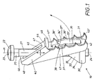
- the Fig. 1 and 2 1 shows an embodiment of the fastening device 10 according to the invention.
- This fastening device 10 comprises a screw 20, a clamping nut 30 and a retaining clip 40.
- the screw 20 has a head 22 with a shaped recess 23, for example a slot, a Phillips, a Torx or other shaped recess.
- the head 22 of the screw 20 is connected to a threaded bolt 21, which is configured on its underside with a straight support surface 24, so that the screw 20 can be supported on a flat surface.
- the external thread of the threaded bolt 21 of the screw 20 cooperates with an internal thread of the clamping nut 30.
- the screw 20 serves to fix the fastening device 10 in the corresponding supply unit and for holding the retaining clip 40, which can be positioned by means of clamping nut 30 in different positions.
- the clamping nut 30 moves from the mounting position, shown in FIG Fig. 1 , along the threaded bolt 21 upwards and takes the headband 40 with.
- the bracket 40 consists in this embodiment of two support arms 41, 41 ', which are both formed on the same side of a flat connecting plate 44 and indeed, as best of Fig. 2 it can be seen that the longitudinal axis L1 of the connecting plate 44 is at an acute angle ⁇ to the longitudinal axis L2 of the retaining arms 41, 41 '.
- This arrangement of the holding arms 41, 41 'on the connecting plate 44 allows the most space-saving mounting position of the fastening device 10, shown in FIG Fig. 1 because the fastening device 10 in this case shows a small width.
- a chamfer 49 may be provided at the end of the connecting plate 44, which in the assembled state of the fastening device 10 in the housing 50 has a supply unit in the direction of the housing 50.
- the headband 40 can in this way in its mounting position, see Fig. 1 , be pivoted a little further.
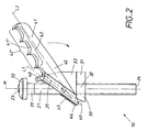
- the connecting plate 44 of the retaining clip 40 is further penetrated by a slot 45.
- the ends of the elongated hole 45 each form a stop 46 and 47, respectively.
- the length of the oblong hole 45 thus limits the possible horizontal movement of the retaining clip 40, since upon movement of the retaining clip 40 to the right of the headband 40 can be moved so far until the screw 20 reaches the end of the slot 45 and touches the stop 46.
- a movement of the retaining clip 40 in the opposite direction, ie to the left is possible until the screw 20 also touches the stop 47.
- the retaining clip 40 can be displaced vertically, namely along the threaded bolt 21 of the screw 20. This movement is also made possible by the oblong hole 45 in the connecting plate 44.
- the vertical movement of the retaining clip 40 is limited by the head 22 of the screw 20 and down through the respective position of the clamping nut 30, which, however, as already described, can be raised or lowered by turning the screw 20.
- the headband 40 can be pivoted. Starting from the mounting position, shown in Fig. 1 , the headband 40 can be pivoted upwards until it is about the position in Fig. 2 has reached. From here, only a slight upward pivoting is possible, since then a projection 48, which represents an extension of the connecting plate 44, abuts the threaded bolt 21 of the screw 20. Swinging back the retaining clip 40 from the position shown in FIG Fig. 2 is not possible because the clamping nut 30 supports the headband 40.
- a row of teeth 42, 42 ' is provided on the upper side of the holding arms 41, 41', wherein in particular the outer tooth 43, 43 'is designed as an incisor.
- This outer cutting tooth 43, 43 ' is used, as in the known from the prior art claw, for fixing the supply unit in a mounting opening of a cavity floor, in particular for clamping on the walls of the mounting opening of the cavity floor.
- Fig. 4 Such a Use of the fastening device 10 is in Fig. 4 shown. It is clearly visible that the cutting tooth 43 cuts into the wall of the cavity floor 62 and thus provides an additional safeguard in addition to the existing clamping force.
- another tooth of the row of teeth 42, 42 ' is used.
- three different clamps were to be used, namely a clamp for steel plates with a thickness of 5 mm to 15 mm, another clamp for a false bottom 63 with a thickness of 15 mm to 35 mm and another clamp for a false bottom 63rd with a thickness of 35 mm to 50 mm.
- the fastening device 10 can be used due to the existing row of teeth 42, 42 'with the spaced teeth provided for raised floors 63 with a thickness of mm to 50 mm.
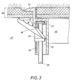
- a floor with a thickness of 5 mm to 15 mm is usually a screed flush duct or a floor duct, shown in Fig. 3 , This application possibility is realized by the fastening device 10 according to the invention.
- the fastening device 10 can already be pre-assembled in the supply unit.
- recesses for the fastening device 10 are provided in the housing 50 of the supply unit in the circumferential housing wall. These recesses do not project beyond the encircling housing wall, they are embedded as vertical channels 52 in the housing wall of the housing 50, preferably with a rectangular or square cross section, wherein the channel walls provided adjacent to the channel opening are provided with locking means.
- Fig. 3 are provided in the channel 52 on the channel side walls ribs 54. Due to the sectional view in Fig. 3 is only a rib 54 to see.
- the headband 40 In the mounting position, the headband 40 is with its rows of teeth 42, 42 'behind the rib 54.
- the rib 54 prevents the pivoting of the retaining clip 40 during Transport and storage of the supply unit. For mounting the supply unit, this is inserted into the corresponding opening in the bottom, since no part of the fastening device 10 projects beyond the channel opening, the insertion of the supply unit into the opening in the bottom 60 is easy to accomplish. Subsequently, by turning the screw 20, the clamping nut 30 is moved until it has brought the headband 40 in the fastening position. In this case, the headband 40 is pivoted. During this pivoting, the rib 54 is pushed aside or optionally sheared off.
- the particular embodiment of the clamping nut 30 is better in the Fig. 1 and 2 shown.
- the clamping nut 30 has a flat base plate 31, in which the threaded bore 32 is located.
- the base plate 31 goes on its sides in vertically upwardly projecting flanges 33, 33 'over. These flanges 33, 33 'have a selected contour.
- the side edges 34, 34 ' which face the housing 50 in the installed state of the fastening device 10, extend diagonally upwards.
- the course of the side edges 34, 34 'starting from the base plate 31 is therefore directed away from the housing 50.
- This inclination is executed to the housing 50.
- the side edges 34, 35 and 34 ', 35' converge in the upper region in a rounding 38, 38 'together.
- the narrow flat surfaces of the side edges 34, 34 ', 36, 36' and the upper rounding 38, 38 ' are used to support the retaining clip 40 in different attachment situations.
- An attachment position is for example in Fig. 2 shown. This attachment situation corresponds approximately to the situation in the determination in a screed-flush channel or on-floor channel, as in Fig. 3 shown. Starting from the mounting position, shown in Fig.
- the clamping nut 30 moves upward upon rotation of the screw 20, this due to the interaction of the external thread of the threaded bolt 21 with the internal thread of the threaded bore 32 of the clamping nut 30.
- the clamping nut 30th is raised in this way until the rounding 38, 38 'presses against the supernatant 48.
- the retaining clip 40 is subsequently pivoted upon further lifting of the clamping nut 30.
- This headband 40 lies with its connecting plate 44 on the side edges 34, 34 '.
- the narrow flat surfaces of these side edges 34, 34 ' serve as a support surface 35, 35'. In this situation, if a tooth of the row of teeth 42, 42 'lies on the underside of a bottom 60, as in FIG Fig.
- Fig. 4 and 5 show the use of the same fastening device 10 for other installation situations, namely in Fig. 4
- the fastening device 10 can be pivoted from its mounting position out only slightly until it touches the wall of the cavity bottom 62.
- the connecting plate 44 is pressed in this case against the contact surfaces 37, 37 'of the side edges 36, 36' and provided at the free end of the retaining bracket 40 cutting teeth 43, 43 'intersect in the Wall of the cavity floor 62 a.
- the attachment is thus ensured by the bracing and the cutting action.
- the same fastening device 10 is used to define a supply unit in a false floor 63.
- the fastening device 10 was pre-assembled in the same way in the channel 52 of the housing 50.
- the clamping nut 30 is tightened.
- the retaining clip 40 can pivot further until a tooth of the row of teeth 42, 42 'touches the underside of the double bottom 63. By grasping under the raised floor 63 a secure attachment of the supply unit is guaranteed.
- fastening device 10 After a fastening device 10 has been brought into the fastening position, further fastening devices 10, which are provided in further channels 52 of the housing 50 of the supply unit, can be brought into the fastening position by turning the respective screw 20, preferably six fastening devices 10 for a round floor box provided, with always two fastening devices 10 are diametrically opposed. After all fastening devices 10 are brought into the fastening position, the cover, the cover plate or, as in this case, a steel plate 51 can be placed and the supply unit is covered with it.
- the particular advantage of the fastening device 10 according to the invention is that a supply unit, which is equipped with these fastening devices 10, in openings of different floors 60, 62, 63 can be used. It is only a fastening device 10 required for the different applications, compared to at least four different fasteners in the prior art, namely three brackets for different thicknesses of the common double floors or steel plates and for fixing by means of a claw in the cavity floor. Furthermore, the assembly of the supply unit is simplified. The customer no longer has to decide in advance which fastening means must be mounted on the supply unit to be supplied. He can without Time delay insert the supply unit into the opening of the floor. In addition, the storage reduces, since only one fastening device 10 instead of 4 fasteners must be stored. The transport of the equipped with fastening devices 10 supply units is less problematic due to existing locking means and involves less risk of injury.
Landscapes
- Engineering & Computer Science (AREA)
- General Engineering & Computer Science (AREA)
- Mechanical Engineering (AREA)
- Connection Of Plates (AREA)
- Details Of Spanners, Wrenches, And Screw Drivers And Accessories (AREA)
- Clamps And Clips (AREA)
Applications Claiming Priority (2)
| Application Number | Priority Date | Filing Date | Title |
|---|---|---|---|
| DE200810008550 DE102008008550B4 (de) | 2008-02-12 | 2008-02-12 | Befestigungsvorrichtung |
| DE200820001890 DE202008001890U1 (de) | 2008-02-12 | 2008-02-12 | Befestigungsvorrichtung |
Publications (2)
| Publication Number | Publication Date |
|---|---|
| EP2090790A2 true EP2090790A2 (fr) | 2009-08-19 |
| EP2090790A3 EP2090790A3 (fr) | 2014-09-24 |
Family
ID=40521417
Family Applications (1)
| Application Number | Title | Priority Date | Filing Date |
|---|---|---|---|
| EP09001600.7A Withdrawn EP2090790A3 (fr) | 2008-02-12 | 2009-02-05 | Dispositif de fixation |
Country Status (1)
| Country | Link |
|---|---|
| EP (1) | EP2090790A3 (fr) |
Citations (9)
| Publication number | Priority date | Publication date | Assignee | Title |
|---|---|---|---|---|
| US1797765A (en) * | 1929-01-25 | 1931-03-24 | Bull Dog Electric Products Com | Trim clamp |
| DE1928973A1 (de) * | 1969-06-07 | 1970-12-10 | Merten Geb | Spreizbefestigung fuer elektrische Up-Installationsapparate |
| DE2355826A1 (de) * | 1973-11-08 | 1975-05-22 | Spelsberg Guenther Kg | Wanddose fuer elektroinstallationszwecke |
| FR2743673A1 (fr) * | 1996-01-17 | 1997-07-18 | Arnould App Electr | Support d'appareillage a rapporter sur une boite d'encastrement et sous-ensemble vis-griffe propre a equiper un tel support d'appareillage |
| AT3234U1 (de) * | 1998-11-30 | 1999-11-25 | Legrand Oesterreich | Elektrisches installationsgerät |
| EP1071184A1 (fr) * | 1999-07-19 | 2001-01-24 | Legrand | Griffe d'ancrage à deux zones géographiques d'action distinctes pour mécanisme électrique |
| US20010002018A1 (en) * | 1998-01-27 | 2001-05-31 | Jean-Paul Goudal | A wall recessible box for electrical apparatus |
| EP1187285A2 (fr) * | 2000-09-07 | 2002-03-13 | Gewiss S.P.A. | Dispositif de verrouillage en particulier pour retenir un cadre d'insertion pour un boítier |
| WO2009027469A1 (fr) * | 2007-08-29 | 2009-03-05 | Schneider Electric Danmark A/S | Griffe |
-
2009
- 2009-02-05 EP EP09001600.7A patent/EP2090790A3/fr not_active Withdrawn
Patent Citations (9)
| Publication number | Priority date | Publication date | Assignee | Title |
|---|---|---|---|---|
| US1797765A (en) * | 1929-01-25 | 1931-03-24 | Bull Dog Electric Products Com | Trim clamp |
| DE1928973A1 (de) * | 1969-06-07 | 1970-12-10 | Merten Geb | Spreizbefestigung fuer elektrische Up-Installationsapparate |
| DE2355826A1 (de) * | 1973-11-08 | 1975-05-22 | Spelsberg Guenther Kg | Wanddose fuer elektroinstallationszwecke |
| FR2743673A1 (fr) * | 1996-01-17 | 1997-07-18 | Arnould App Electr | Support d'appareillage a rapporter sur une boite d'encastrement et sous-ensemble vis-griffe propre a equiper un tel support d'appareillage |
| US20010002018A1 (en) * | 1998-01-27 | 2001-05-31 | Jean-Paul Goudal | A wall recessible box for electrical apparatus |
| AT3234U1 (de) * | 1998-11-30 | 1999-11-25 | Legrand Oesterreich | Elektrisches installationsgerät |
| EP1071184A1 (fr) * | 1999-07-19 | 2001-01-24 | Legrand | Griffe d'ancrage à deux zones géographiques d'action distinctes pour mécanisme électrique |
| EP1187285A2 (fr) * | 2000-09-07 | 2002-03-13 | Gewiss S.P.A. | Dispositif de verrouillage en particulier pour retenir un cadre d'insertion pour un boítier |
| WO2009027469A1 (fr) * | 2007-08-29 | 2009-03-05 | Schneider Electric Danmark A/S | Griffe |
Also Published As
| Publication number | Publication date |
|---|---|
| EP2090790A3 (fr) | 2014-09-24 |
Similar Documents
| Publication | Publication Date | Title |
|---|---|---|
| EP3787137A1 (fr) | Dispositif de raccordement, garniture de raccordement et chemin de câbles | |
| DE102005000020B4 (de) | Anordnung zur Halterung eines Installationsgeräte-Einsatzes an einer Tragplatte | |
| DE102008008550B4 (de) | Befestigungsvorrichtung | |
| DE202008001890U1 (de) | Befestigungsvorrichtung | |
| AT509757B1 (de) | Vorrichtung zum haltern eines plattenheizkörpers | |
| EP2426291B1 (fr) | Profil universel en trois parties | |
| EP2090790A2 (fr) | Dispositif de fixation | |
| WO2002037633A2 (fr) | Boite encastree a monter sans outils | |
| DE4312480C2 (de) | Sammelschienenträger | |
| DE202011100808U1 (de) | Kabelkanal | |
| DE102010013433B4 (de) | Geräteeinsatz für Installationsgeräte | |
| EP3045743A1 (fr) | Fixation de structure porteuse pour un repartiteur de fluide, agencement de montage et procede de montage d'un repartiteur de fluide | |
| DE69707753T2 (de) | Verbesserung an Montagesatz für Metallschaltschranktürscharniere | |
| EP0809339B1 (fr) | Appareil pour installation électrique | |
| DE29912232U1 (de) | Schraubwerkzeug | |
| DE4327077C2 (de) | Haltevorrichtung zur hängenden Aufnahme eines Heizkörpers o. dgl. | |
| DE102005010026B4 (de) | Regalsystem | |
| DE29510748U1 (de) | Säule | |
| DE602006000377T2 (de) | Befestigungsvorrichtung für einen Befestigungsring auf einem Tragelement der diesen umfasst | |
| EP4246745A1 (fr) | Sortie de conduite | |
| WO2022171551A1 (fr) | Dispositif de traversée de brins de câble | |
| EP2896861B1 (fr) | Console de montage réglable destinée à la fixation d'un canal de guidage de conduite sur un mur | |
| DE102021200328A1 (de) | Steuerungsgehäuse für ein Kochfeld und Kochfeld | |
| DE29509556U1 (de) | Schaltschrank mit Montageplatte | |
| EP3663653A1 (fr) | Dispositif modulaire de retenue d'un radiateur et ensemble de fixation correspondant |
Legal Events
| Date | Code | Title | Description |
|---|---|---|---|
| PUAI | Public reference made under article 153(3) epc to a published international application that has entered the european phase |
Free format text: ORIGINAL CODE: 0009012 |
|
| AK | Designated contracting states |
Kind code of ref document: A2 Designated state(s): AT BE BG CH CY CZ DE DK EE ES FI FR GB GR HR HU IE IS IT LI LT LU LV MC MK MT NL NO PL PT RO SE SI SK TR |
|
| AX | Request for extension of the european patent |
Extension state: AL BA RS |
|
| RIC1 | Information provided on ipc code assigned before grant |
Ipc: F16B 2/06 20060101AFI20140428BHEP |
|
| PUAL | Search report despatched |
Free format text: ORIGINAL CODE: 0009013 |
|
| AK | Designated contracting states |
Kind code of ref document: A3 Designated state(s): AT BE BG CH CY CZ DE DK EE ES FI FR GB GR HR HU IE IS IT LI LT LU LV MC MK MT NL NO PL PT RO SE SI SK TR |
|
| AX | Request for extension of the european patent |
Extension state: AL BA RS |
|
| RIC1 | Information provided on ipc code assigned before grant |
Ipc: F16B 2/06 20060101AFI20140819BHEP |
|
| AKY | No designation fees paid | ||
| AXX | Extension fees paid |
Extension state: RS Extension state: BA Extension state: AL |
|
| REG | Reference to a national code |
Ref country code: DE Ref legal event code: R108 |
|
| STAA | Information on the status of an ep patent application or granted ep patent |
Free format text: STATUS: THE APPLICATION IS DEEMED TO BE WITHDRAWN |
|
| 18D | Application deemed to be withdrawn |
Effective date: 20150325 |