EP2090529B1 - Dispositif destiné à la manipulation d'emballages de médicaments - Google Patents
Dispositif destiné à la manipulation d'emballages de médicaments Download PDFInfo
- Publication number
- EP2090529B1 EP2090529B1 EP08002580.2A EP08002580A EP2090529B1 EP 2090529 B1 EP2090529 B1 EP 2090529B1 EP 08002580 A EP08002580 A EP 08002580A EP 2090529 B1 EP2090529 B1 EP 2090529B1
- Authority
- EP
- European Patent Office
- Prior art keywords
- shelf
- manipulator
- compartments
- spring steel
- shelves
- Prior art date
- Legal status (The legal status is an assumption and is not a legal conclusion. Google has not performed a legal analysis and makes no representation as to the accuracy of the status listed.)
- Active
Links
- 239000003814 drug Substances 0.000 title description 39
- 238000006073 displacement reaction Methods 0.000 claims description 32
- 229910000639 Spring steel Inorganic materials 0.000 claims description 27
- 229920003023 plastic Polymers 0.000 claims description 3
- 229940079593 drug Drugs 0.000 description 31
- 238000001514 detection method Methods 0.000 description 6
- 230000000284 resting effect Effects 0.000 description 2
- OKTJSMMVPCPJKN-UHFFFAOYSA-N Carbon Chemical compound [C] OKTJSMMVPCPJKN-UHFFFAOYSA-N 0.000 description 1
- 230000000739 chaotic effect Effects 0.000 description 1
- 229920002457 flexible plastic Polymers 0.000 description 1
- 238000004519 manufacturing process Methods 0.000 description 1
- 239000000203 mixture Substances 0.000 description 1
- 238000012946 outsourcing Methods 0.000 description 1
Images

Classifications
-
- B—PERFORMING OPERATIONS; TRANSPORTING
- B65—CONVEYING; PACKING; STORING; HANDLING THIN OR FILAMENTARY MATERIAL
- B65G—TRANSPORT OR STORAGE DEVICES, e.g. CONVEYORS FOR LOADING OR TIPPING, SHOP CONVEYOR SYSTEMS OR PNEUMATIC TUBE CONVEYORS
- B65G1/00—Storing articles, individually or in orderly arrangement, in warehouses or magazines
- B65G1/02—Storage devices
- B65G1/04—Storage devices mechanical
- B65G1/0407—Storage devices mechanical using stacker cranes
- B65G1/0435—Storage devices mechanical using stacker cranes with pulling or pushing means on either stacking crane or stacking area
Definitions
- the invention relates to a device for handling pharmaceutical packages on a shelf storage for pharmacies, with at least one shelf whose shelves are open towards a computer-controlled manipulator, which serves for inserting, removing and picking of drug packages and led to guides computer controlled before Shelf is movable, wherein the manipulator has a plurality of open in the direction of the shelves receiving compartments, which are arranged next to and / or one above the other, wherein the manipulator is computer controlled so displaced that each receiving compartment of the manipulator is positionable in front of each shelf of the shelf, and wherein each Receptacle of the manipulator a computer-controlled displacement device for pulling drug packages from the shelf of the shelf in the opposite receiving compartment of the manipulator and for pushing Arzeistoffpackonne from the receiving compartment of the manipulator in the gege Overlying shelf of the shelf is assigned.
- Such a device is for example from the WO 03/043912 A1 known.
- this prior art device are each several drug packages in storage containers that are inserted into the shelves or can be pulled out of these shelves out in the receiving compartments of the manipulator. To put together commissions, the individual drug packages must be taken out of its storage containers within the manipulator and reloaded into separate order picking containers. This reloading is machine and Operational extremely cumbersome and time consuming.
- the displacement device arranged in each receiving compartment of the manipulator uses hydraulic cylinders as the displacement member, which are arranged below a guide frame and are each provided with a lifting device which raises the hydraulic cylinder to the working position. This embodiment of the displacement device requires a high apprativen effort and allows only relatively small displacement paths.
- Another problem is that the manipulator always has only the respective drug package lying in front of the shelf in the access. This is particularly problematic when - as usual in the so-called chaotic storage - in a shelf successively different drug packages are. In order to get in this case to the further back in the row drug packages, the front drugs must first be removed from the previously known pharmacy warehouse and stored elsewhere, before the more distant drug packages are accessible. This leads to the compilation of drug commissions to very long travel distances of the manipulator and a corresponding time consumption.
- the invention proposes that arranged in the receiving compartments of the manipulator sliding devices each have a serving as a displacement spring steel band which is stiffened in the extended state by a transverse to its longitudinal direction buckle and formed flat in the bent state transverse to its longitudinal direction is.
- a spring steel band is sufficiently rigid for the pulling and pushing of the drug packages and yet can be easily bent to be space-saving deflected and / or stored at the rear end or behind the respective receiving compartment.
- a computer-controlled displacement drive is assigned to the stretched portion of the spring steel strip.
- This displacement drive is expediently formed by a gear wheel driven by a stepping motor which engages in a flexible toothed rack associated with the spring steel strip.
- This flexible rack can either be formed on the spring steel strip itself or be connected to the spring steel strip.
- This rack can be formed for example by a glued under the spring steel strip flexible plastic rack.
- the front end of the spring steel strip is expediently associated with a sliding carriage, which easily slides over the gap between the manipulator and the shelf during operation of the displacement device and at the same time is provided with a suitable fixation device for the medicament pack to be moved.
- This fixing device is expediently formed by a suction head attached to the sliding carriage, which is provided for holding and / or releasing medicament packs to be moved.
- This suction head is expediently connected to a suction hose extending along the spring steel strip, by means of which the suction head can be connected to a vacuum in a controlled manner.
- a controlled suction head has no moving parts for holding and releasing the respective drug package and is therefore inexpensive and less prone to very low production costs.
- suction hose, the flexible rack and the spring steel strip may be connected to a structural unit, for. B. glued together.
- suction hose with the flexible rack is made in one piece from plastic and is connected in a suitable manner with the spring steel strip.
- the number of required computer-controlled displacement devices is limited to the number of receiving compartments in the manipulator. Accordingly, you can significantly increase the number of shelves without this would have a significant impact on the required mechanical complexity.
- the significantly lower mechanical complexity of the pharmacy warehouse according to the invention is well suited for the composition of commissions, even if individual pharmaceutical packages of the Commission are not on the front shelf. In this case you can namely cache in one or more receiving compartments of the manipulator, the forward false packages, then store in other receiving compartments of the manipulator Gutpackungen and finally push the intermediate misplaced packs in appropriate shelves without the manipulator this would have to travel long distances.
- the device according to the invention has at least two shelves arranged one behind the other in the loading direction, wherein the front shelf to release the rear shelf is computer-controlled laterally displaceable and the manipulator also computer-controlled in his guides towards the rear shelf is displaceable.
- the bottoms of the shelves of the shelf storage and the receiving compartments of the manipulator are each V-shaped.
- This V-shaped design of the shelves shelf of the shelf on the one hand and the receiving compartments of the manipulator on the other hand facilitates the alignment of the receiving compartments of the manipulator on the shelves of the shelves considerably.
- only the vertexes of the two V-shaped bottoms need to be aligned.
- a further advantage of the V-shaped bottoms is that the medicament packs resting on the trays are automatically centered in the receiving compartment or shelf compartment and guided exactly linearly during their displacement.
- the manipulator has on its upper side at least one receiving compartment, which is open at the top.
- Such an upwardly open receptacle is provided for particularly bulky medicament packs, the height of which may be different, but which are still safely taken up and fixed by the upwardly open V-shaped bottom of the receptacle.
- each Shelf of the manipulator is positioned in front of this transfer floor.
- medicament packs can also be removed from the device via this transfer bottom, specifically in that the manipulator retrieves medicament packs from the shelves and then pushes them back onto the delivery floor.
- the transfer floor of the central detection station as well as the bottoms of the receiving compartments of the manipulator and the bottoms of the shelves V-shaped.
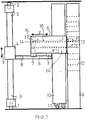
- FIG. 1 As can be seen, the device for handling drug packages on two guide rails 1 and 2, which are mounted on the floor and ceiling of a storage room and where a guide frame 3 along a direction x (ie in FIG. 1 perpendicular to the plane of the drawing) computer-controlled is movable.
- a lifting table 5 On the guide frame 3, a lifting table 5 is guided vertically via sliding guides 4, ie in the direction y. The displacements of the lifting table 5 in the direction y are also exactly computer-controlled.
- a manipulator 6 On the lifting table 5, a manipulator 6 is mounted horizontally displaceable in the direction z. For this purpose, the manipulator 6 is guided on slides 7 on the lifting table 5 in guides 8. The displacement of the manipulator 6 in the z-direction is also exactly computer-controlled.
- the manipulator 6 Opposite the manipulator 6 are two shelves, namely a fixed rear shelf 9 and a sliding shelf 10 arranged in front of it.
- the movable shelf 10 can be moved on slide rails 11 in the x-direction such that it is stationary from the manipulator 6 Shelf 9 obscures or releases.
- the manipulator 6 is movable on the lifting table in the z-direction so that it can operate both shelves 9 and 10, in the retracted position the front shelf 10 and in the advanced position (see. FIG. 1
- the rear shelf 9 of course.
- the displacement of the front shelf 10 in the x-direction is of course also computer-controlled, so that the exact position of the manipulator 6 relative to the shelf 10 can be determined.
- the shelves 9 and 10 have a plurality of shelves 12, in which drug packages 13 can be stored chaotically.
- the shelves 12 are open in the direction of the manipulator 6 and can be loaded and unloaded by the manipulator 6 on this open side.
- the manipulator 6 includes a plurality of over and / or juxtaposed receiving compartments 14, in each of which computer-controlled displacement devices 15 are arranged. These computer-controlled displacement devices are used to pull drug packages 13 from the respective opposite shelf 12 into the receptacle 14 of the manipulator 6 or to push drug packages 13 from the receptacle 14 of the manipulator 6 in the opposite shelf 12 of the shelf 9 or 10.
- the manipulator 6 So suitable for both storage and outsourcing of drug packages 13.
- the manipulator 6 has a plurality of receiving compartments 14 (eight in the exemplary embodiment)
- the manipulator 6 has on its upper side two upwardly open receiving compartments 14 for receiving particularly bulky medicament packs 13. Moreover, it can be seen from the drawing that the shelves 12 of the shelves 9 and 10 and the receiving compartments 14 of the manipulator 6 each formed V-shaped. This has the advantage that the drug packages 13 resting on these trays center in the center of each compartment. In addition, it is easier with the V-shaped bottoms to align the respective receiving compartments 15 of the manipulator 6 exactly to the respectively to be operated shelf 12 of the shelves 9 or 10. For this purpose, the manipulator needs only to be controlled and moved so that the vertexes of the two aligned V-shaped bottoms are exactly in line. This also applies if the shelves 12 are subdivided by shelves 12 insertable shelves into several smaller shelves, each with V-shaped bottoms. Each of these small shelves can be easily approached with the manipulator 6 exactly.
- FIGS. 3 and 4 in particular details of the arranged in the individual receiving compartments 14 of the manipulator 6 displacement devices 15 recognize.
- These displacement devices 15 use as a displacement member a curved spring steel strip 16, which - is stiffened in the stretched state by its transversely to the longitudinal direction extending curvature and is flat in the bent state transverse to its longitudinal direction and is accordingly easy to bend - like a spring steel tape measure.
- this spring band 16 can be easily deflected at the rear end of the displacement path within the receiving compartment 14 and can be kept wound up in the manner of a spring steel tape to a roll 17.
- the stretched portion of the spring steel strip 16 is associated with a computer-controlled displacement drive 18 (see. FIG. 3 ), which has a driven by a stepper motor gear 19 which engages in a fixed to the spring steel strip 16 flexible toothed rack 20 made of plastic.
- This toothed rack 20 is at the same time designed as a suction hose 21 for a suction head 22 attached to the front end of the spring steel strip 16.
- This suction head 22 is located on a sliding carriage 23 which slides on the V-shaped bottom of the receiving compartment 14 of the manipulator 6 and in further advanced state of the shelf compartment 12 of the shelf 9 and 10, respectively.
- the suction head 22 is connected via the suction hose 21 with the interposition of control valves 24 with a vacuum source, not shown, and can fix the corresponding thereto drug package 13 by suction by appropriate control or release by pressure equalization.
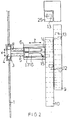
- FIG. 2 It can be seen, in addition to the shelf 9 a central detection station for the imported andmenbagernden drug packages provided.
- This central detection station is the subject of a parallel patent application and therefore not described in detail here.
- This central detection station has a transfer floor 25 for the drug packages to be stored and outsourced.
- This transfer floor 25 is thus transport technology, the interface between the central detection station and the above-described device for handling drug packages.
- This interface is also operated by the manipulator according to the invention.
- the transfer floor 25 is arranged in front of the manipulator 6 and its guide system such that each receiving compartment 14 of the manipulator 6 can be positioned in front of this transfer floor 25.
- the transfer or removal of drug packages is carried out in the same manner as in the previously described shelves.
- the transfer floor 25 is just like the bottoms of the receiving compartments 14 of the manipulator 6 and the bottoms of the shelves 12 V-shaped, which has already explained above advantages in terms of the orientation of the manipulator 6, the leadership of the drug packages during the transfer.
- the shelves 9 and 10 are arranged only to the right of the manipulator 6. Deviating from the embodiment but can be arranged on both sides of the manipulator 6 shelves. In this case, the manipulator 6 is provided on both sides with storage compartments 14 and their associated displacement devices 15. Alternatively, the manipulator may also be reversibly guided in order to be able to operate shelves in this manner on the right and left of its travel path.
Claims (15)
- Dispositif pour la manipulation d'emballages de médicaments dans un entrepôt à rayonnage pour des pharmacies, ayant au moins un rayonnage, dont les rayons sont ouverts dans une direction vers un manipulateur commandé par ordinateur qui est utilisé pour introduire, prendre et commissionner des emballages de médicaments, et qui peut être déplacé en face du rayonnage de manière commandée par ordinateur en étant guidé par des guides, dans lequel le manipulateur (6) présente plusieurs compartiments de stockage (14) ouverts dans la direction des rayons (12), qui sont disposés les uns à côté et/ou au-dessus des autres, dans lequel le manipulateur (6) peut se déplacer de manière commandée par ordinateur de telle sorte que chaque compartiment de stockage (14) du manipulateur (6) peut être positionné devant chaque rayon (12) du rayonnage (9, 10), et dans lequel chaque compartiment de stockage (14) du manipulateur (6) comporte un dispositif de déplacement commandé par ordinateur (15) pour tirer des emballages de médicaments (13) du rayon (12) du rayonnage (9, 10) jusque dans le compartiment de stockage opposé (15) du manipulateur (6), de même que pour pousser des emballages de médicaments (13) hors du compartiment de stockage (14) du manipulateur (6) jusque dans le rayon opposé (12) du rayonnage (9, 10),
caractérisé en ce que
les dispositifs de déplacement (15) disposés dans les compartiments de stockage (14) du manipulateur (6) présentent chacun une bande en acier à ressort servant d'organe de déplacement (16), qui est raidie dans un état étiré par une voûte s'étendant transversalement à sa direction longitudinale, et qui est formée plate dans un état cintré transversalement à sa direction longitudinale. - Dispositif selon la revendication 1, caractérisé en ce que la bande en acier à ressort (16) est stockée enroulée à l'extrémité arrière de la course de déplacement en un rouleau (17).
- Dispositif selon la revendication 2, caractérisé en ce que le tronçon étiré de la bande en acier à ressort (16) est associé à un entraînement de déplacement commandé par ordinateur (18).
- Dispositif selon la revendication 3, caractérisé en ce que l'entraînement de déplacement (18) comprend une roue dentée (19) entraînée par un moteur pas à pas, qui vient en prise avec une crémaillère flexible (20) associée à la bande en acier à ressort (16).
- Dispositif selon la revendication 4, caractérisé en ce que l'extrémité avant de la bande en acier à ressort (16) est associée à un chariot coulissant (23).
- Dispositif selon la revendication 5, caractérisé en ce que le chariot coulissant (23) est prévu avec une tête d'aspiration (22) pour le maintien et/ou la libération d'emballages de médicaments (13) devant être déplacés.
- Dispositif selon la revendication 6, caractérisé en ce que la tête d'aspiration (22) est reliée à un flexible d'aspiration (21) s'étendant le long de la bande en acier à ressort (16), auquel la tête d'aspiration (23) peut être reliée de manière commandée par un vide.
- Dispositif selon la revendication 7, caractérisé en ce que le flexible d'aspiration (21) et la crémaillère flexible (20) (16) sont reliés à la bande en acier à ressort pour former une unité structurelle.
- Dispositif selon la revendication 8, caractérisé en ce que le flexible d'aspiration (21) et la crémaillère flexible (20) sont réalisés d'un seul tenant en matière plastique.
- Dispositif selon la revendication 1, caractérisé par au moins deux rayons (9, 10) agencés à la suite dans la direction d'insertion, dans lequel le rayon avant (10) peut être déplacé de manière commandée par ordinateur pour libérer le rayon arrière (9), et le manipulateur (6) peut également être déplacé de manière commandée par ordinateur via ses guides (8) en direction du rayon arrière (9).
- Dispositif selon la revendication 1 ou 10, caractérisé en ce que les planchers des rayons (12) des rayonnages (9, 10) et le compartiment de stockage (14) du manipulateur (6) sont formés chacun en forme de V.
- Dispositif selon la revendication 11, caractérisé en ce que les rayons (12) peuvent être divisés par des planchers intermédiaires opérationnels en rayons plus petits, à l'aide de planchers également en forme de V.
- Dispositif selon la revendication 1, caractérisé en ce que le manipulateur (6), sur sa face supérieure, présente au moins un compartiment de stockage (14), qui est formé ouvert vers le haut.
- Dispositif selon la revendication 1 ou 10, caractérisé en ce qu'à côté ou au-dessus des rayonnages (9, 10) est disposée une station centrale d'enregistrement fonctionnant de manière automatisée pour les emballages de médicaments (13) qui entrent et qui sortent, qui présente au moins un plancher de transfert (25) qui donne vers le compartiment de stockage (14) du manipulateur (6) pour les emballages de médicament (13) qui entrent et qui sortent, dans lequel chaque compartiment de stockage (14) du manipulateur (6) peut être positionné devant ce plancher de transfert (25).
- Dispositif selon la revendication 14, caractérisé en ce que le plancher de transfert (25) de la station centrale d'enregistrement, ainsi que les planchers du compartiment de stockage (14) du manipulateur (6) et les planchers des rayons sont formés en forme de V.
Priority Applications (2)
| Application Number | Priority Date | Filing Date | Title |
|---|---|---|---|
| EP08002580.2A EP2090529B1 (fr) | 2008-02-12 | 2008-02-12 | Dispositif destiné à la manipulation d'emballages de médicaments |
| HUE08002580A HUE030804T2 (hu) | 2008-02-12 | 2008-02-12 | Berendezés gyógyszercsomagok kezelésére |
Applications Claiming Priority (1)
| Application Number | Priority Date | Filing Date | Title |
|---|---|---|---|
| EP08002580.2A EP2090529B1 (fr) | 2008-02-12 | 2008-02-12 | Dispositif destiné à la manipulation d'emballages de médicaments |
Publications (2)
| Publication Number | Publication Date |
|---|---|
| EP2090529A1 EP2090529A1 (fr) | 2009-08-19 |
| EP2090529B1 true EP2090529B1 (fr) | 2016-06-22 |
Family
ID=39514652
Family Applications (1)
| Application Number | Title | Priority Date | Filing Date |
|---|---|---|---|
| EP08002580.2A Active EP2090529B1 (fr) | 2008-02-12 | 2008-02-12 | Dispositif destiné à la manipulation d'emballages de médicaments |
Country Status (2)
| Country | Link |
|---|---|
| EP (1) | EP2090529B1 (fr) |
| HU (1) | HUE030804T2 (fr) |
Families Citing this family (4)
| Publication number | Priority date | Publication date | Assignee | Title |
|---|---|---|---|---|
| DE102007007411A1 (de) | 2007-02-12 | 2008-08-14 | Michael Marquardt | Verfahren und Vorrichtung zum Einlagern von Arzneimittelpackungen |
| CA2678214C (fr) * | 2008-09-09 | 2016-12-13 | Walter Winkler | Systeme transporteur, dispositif d'entreposage et de recuperation et systeme logistique |
| CN103738638B (zh) * | 2013-12-30 | 2016-03-02 | 苏州艾隆科技股份有限公司 | 一种模块化加药槽 |
| CN108030400A (zh) * | 2018-01-21 | 2018-05-15 | 深圳市邂逅科技有限公司 | 一种机器人自动烹饪抽屉柜 |
Family Cites Families (3)
| Publication number | Priority date | Publication date | Assignee | Title |
|---|---|---|---|---|
| DE29505214U1 (de) * | 1995-03-28 | 1996-08-01 | Willach Gmbh Geb | Regallager mit Ziehregalen |
| DE10000684A1 (de) | 2000-01-10 | 2001-07-12 | Michael Marquardt | Regallager mit Entnahmevorrichtung |
| ITBO20010701A1 (it) * | 2001-11-20 | 2003-05-20 | Swisslong Italia S P A | Sistema per lo stoccaggio ed il recupero automatico di oggetti , e dispositivo di trasferimento impiegato nel sistema . |
-
2008
- 2008-02-12 HU HUE08002580A patent/HUE030804T2/hu unknown
- 2008-02-12 EP EP08002580.2A patent/EP2090529B1/fr active Active
Also Published As
| Publication number | Publication date |
|---|---|
| EP2090529A1 (fr) | 2009-08-19 |
| HUE030804T2 (hu) | 2017-05-29 |
Similar Documents
| Publication | Publication Date | Title |
|---|---|---|
| EP1820754B1 (fr) | Système d'étagère et procédé de stockage automatisé de petits objets | |
| DE19509951C2 (de) | Vorrichtung zum unsortierten Lagern von Waren oder sonstigen Gegenständen | |
| DE202012012928U1 (de) | Vorrichtung zum Lagern von Waren, insbesondere Arzneimitteln | |
| EP1818282B1 (fr) | Procédé de déstockage de marchandises au détail d'un entrepôt de marchandises au détail automatisé | |
| DE102016116498A1 (de) | Verfahren zum Aufnehmen eines Probengefäßes aus einem Probenträger und zur Durchführung des Verfahrens ausgebildete Vorrichtung | |
| EP2090529B1 (fr) | Dispositif destiné à la manipulation d'emballages de médicaments | |
| EP2093166B1 (fr) | Procedé pour le déstockage rapide des articles d'un magasin de stockage et un magasin de stockage correspondant | |
| DE10140958A1 (de) | Regallager mit Schiebern in den Regalfächern | |
| DE3514932A1 (de) | Mechanischer schrank | |
| DE102004046176B4 (de) | Verfahren zum rechnergesteuerten Ein- und Auslagern von Gegenständen und Vorrichtung zur Durchführung dieses Verfahrens | |
| DE102016111042A1 (de) | Greifvorrichtung | |
| EP1642850B1 (fr) | Magasin à rayonnage avec manipulateur avec tête de préhension par dépression | |
| EP0816261B1 (fr) | Magazin à rayonnage déplaçable | |
| DE102020111767A1 (de) | Regalbediengerät | |
| DE102004025070C5 (de) | Verfahren und Vorrichtung zur Einlagerung von Waren in eine automatisierte Lagervorrichtung | |
| EP2163491B1 (fr) | Automate de stockage | |
| EP1744974A1 (fr) | Support a rayonnages presentant des separateurs amovibles sur le fond des rayonnages | |
| EP1524209B1 (fr) | Méthode et dispositif pour prélever simultanément plusieurs articles d'un magasin à rayonnage | |
| DE102005035262A1 (de) | Regallager mit Eingabestation | |
| DE10000684A1 (de) | Regallager mit Entnahmevorrichtung | |
| EP1218266B1 (fr) | Gerbeur pour systeme de stockage a rayonnages | |
| EP2015265A2 (fr) | Système d'étagères obliques | |
| EP1862405B1 (fr) | Procédé destiné à saisir une marchandise à l'aide d'éléments de préhension dans un dispositif de stockage et de déstockage et dispositif correspondant | |
| EP0416627A1 (fr) | Procédé et dispositif pour stocker et reprendre automatiquement des sortes de marchandises de détail de rayonnages dans de grands entrepôts | |
| EP2163492A2 (fr) | Entrepôt combiné |
Legal Events
| Date | Code | Title | Description |
|---|---|---|---|
| PUAI | Public reference made under article 153(3) epc to a published international application that has entered the european phase |
Free format text: ORIGINAL CODE: 0009012 |
|
| AK | Designated contracting states |
Kind code of ref document: A1 Designated state(s): AT BE BG CH CY CZ DE DK EE ES FI FR GB GR HR HU IE IS IT LI LT LU LV MC MT NL NO PL PT RO SE SI SK TR |
|
| AX | Request for extension of the european patent |
Extension state: AL BA MK RS |
|
| AKX | Designation fees paid |
Designated state(s): AT BE BG CH CY CZ DE DK EE ES FI FR GB GR HR HU IE IS IT LI LT LU LV MC MT NL NO PL PT RO SE SI SK TR |
|
| 17P | Request for examination filed |
Effective date: 20100615 |
|
| 17Q | First examination report despatched |
Effective date: 20100907 |
|
| RAP1 | Party data changed (applicant data changed or rights of an application transferred) |
Owner name: MARQUARDT UND WURM GBR |
|
| GRAP | Despatch of communication of intention to grant a patent |
Free format text: ORIGINAL CODE: EPIDOSNIGR1 |
|
| INTG | Intention to grant announced |
Effective date: 20151127 |
|
| GRAS | Grant fee paid |
Free format text: ORIGINAL CODE: EPIDOSNIGR3 |
|
| GRAA | (expected) grant |
Free format text: ORIGINAL CODE: 0009210 |
|
| AK | Designated contracting states |
Kind code of ref document: B1 Designated state(s): AT BE BG CH CY CZ DE DK EE ES FI FR GB GR HR HU IE IS IT LI LT LU LV MC MT NL NO PL PT RO SE SI SK TR |
|
| REG | Reference to a national code |
Ref country code: GB Ref legal event code: FG4D Free format text: NOT ENGLISH |
|
| REG | Reference to a national code |
Ref country code: CH Ref legal event code: EP |
|
| REG | Reference to a national code |
Ref country code: IE Ref legal event code: FG4D Free format text: LANGUAGE OF EP DOCUMENT: GERMAN |
|
| REG | Reference to a national code |
Ref country code: AT Ref legal event code: REF Ref document number: 807532 Country of ref document: AT Kind code of ref document: T Effective date: 20160715 |
|
| REG | Reference to a national code |
Ref country code: DE Ref legal event code: R096 Ref document number: 502008014312 Country of ref document: DE |
|
| REG | Reference to a national code |
Ref country code: LT Ref legal event code: MG4D |
|
| REG | Reference to a national code |
Ref country code: NL Ref legal event code: MP Effective date: 20160622 |
|
| PG25 | Lapsed in a contracting state [announced via postgrant information from national office to epo] |
Ref country code: FI Free format text: LAPSE BECAUSE OF FAILURE TO SUBMIT A TRANSLATION OF THE DESCRIPTION OR TO PAY THE FEE WITHIN THE PRESCRIBED TIME-LIMIT Effective date: 20160622 Ref country code: LT Free format text: LAPSE BECAUSE OF FAILURE TO SUBMIT A TRANSLATION OF THE DESCRIPTION OR TO PAY THE FEE WITHIN THE PRESCRIBED TIME-LIMIT Effective date: 20160622 Ref country code: NO Free format text: LAPSE BECAUSE OF FAILURE TO SUBMIT A TRANSLATION OF THE DESCRIPTION OR TO PAY THE FEE WITHIN THE PRESCRIBED TIME-LIMIT Effective date: 20160922 |
|
| PG25 | Lapsed in a contracting state [announced via postgrant information from national office to epo] |
Ref country code: GR Free format text: LAPSE BECAUSE OF FAILURE TO SUBMIT A TRANSLATION OF THE DESCRIPTION OR TO PAY THE FEE WITHIN THE PRESCRIBED TIME-LIMIT Effective date: 20160923 Ref country code: NL Free format text: LAPSE BECAUSE OF FAILURE TO SUBMIT A TRANSLATION OF THE DESCRIPTION OR TO PAY THE FEE WITHIN THE PRESCRIBED TIME-LIMIT Effective date: 20160622 Ref country code: HR Free format text: LAPSE BECAUSE OF FAILURE TO SUBMIT A TRANSLATION OF THE DESCRIPTION OR TO PAY THE FEE WITHIN THE PRESCRIBED TIME-LIMIT Effective date: 20160622 Ref country code: LV Free format text: LAPSE BECAUSE OF FAILURE TO SUBMIT A TRANSLATION OF THE DESCRIPTION OR TO PAY THE FEE WITHIN THE PRESCRIBED TIME-LIMIT Effective date: 20160622 Ref country code: SE Free format text: LAPSE BECAUSE OF FAILURE TO SUBMIT A TRANSLATION OF THE DESCRIPTION OR TO PAY THE FEE WITHIN THE PRESCRIBED TIME-LIMIT Effective date: 20160622 |
|
| PG25 | Lapsed in a contracting state [announced via postgrant information from national office to epo] |
Ref country code: IS Free format text: LAPSE BECAUSE OF FAILURE TO SUBMIT A TRANSLATION OF THE DESCRIPTION OR TO PAY THE FEE WITHIN THE PRESCRIBED TIME-LIMIT Effective date: 20161022 Ref country code: CZ Free format text: LAPSE BECAUSE OF FAILURE TO SUBMIT A TRANSLATION OF THE DESCRIPTION OR TO PAY THE FEE WITHIN THE PRESCRIBED TIME-LIMIT Effective date: 20160622 Ref country code: SK Free format text: LAPSE BECAUSE OF FAILURE TO SUBMIT A TRANSLATION OF THE DESCRIPTION OR TO PAY THE FEE WITHIN THE PRESCRIBED TIME-LIMIT Effective date: 20160622 Ref country code: EE Free format text: LAPSE BECAUSE OF FAILURE TO SUBMIT A TRANSLATION OF THE DESCRIPTION OR TO PAY THE FEE WITHIN THE PRESCRIBED TIME-LIMIT Effective date: 20160622 Ref country code: RO Free format text: LAPSE BECAUSE OF FAILURE TO SUBMIT A TRANSLATION OF THE DESCRIPTION OR TO PAY THE FEE WITHIN THE PRESCRIBED TIME-LIMIT Effective date: 20160622 |
|
| PG25 | Lapsed in a contracting state [announced via postgrant information from national office to epo] |
Ref country code: ES Free format text: LAPSE BECAUSE OF FAILURE TO SUBMIT A TRANSLATION OF THE DESCRIPTION OR TO PAY THE FEE WITHIN THE PRESCRIBED TIME-LIMIT Effective date: 20160622 Ref country code: PL Free format text: LAPSE BECAUSE OF FAILURE TO SUBMIT A TRANSLATION OF THE DESCRIPTION OR TO PAY THE FEE WITHIN THE PRESCRIBED TIME-LIMIT Effective date: 20160622 Ref country code: PT Free format text: LAPSE BECAUSE OF FAILURE TO SUBMIT A TRANSLATION OF THE DESCRIPTION OR TO PAY THE FEE WITHIN THE PRESCRIBED TIME-LIMIT Effective date: 20161024 |
|
| REG | Reference to a national code |
Ref country code: DE Ref legal event code: R097 Ref document number: 502008014312 Country of ref document: DE |
|
| PLBE | No opposition filed within time limit |
Free format text: ORIGINAL CODE: 0009261 |
|
| STAA | Information on the status of an ep patent application or granted ep patent |
Free format text: STATUS: NO OPPOSITION FILED WITHIN TIME LIMIT |
|
| REG | Reference to a national code |
Ref country code: HU Ref legal event code: AG4A Ref document number: E030804 Country of ref document: HU |
|
| 26N | No opposition filed |
Effective date: 20170323 |
|
| PG25 | Lapsed in a contracting state [announced via postgrant information from national office to epo] |
Ref country code: BE Free format text: LAPSE BECAUSE OF NON-PAYMENT OF DUE FEES Effective date: 20170228 Ref country code: DK Free format text: LAPSE BECAUSE OF FAILURE TO SUBMIT A TRANSLATION OF THE DESCRIPTION OR TO PAY THE FEE WITHIN THE PRESCRIBED TIME-LIMIT Effective date: 20160622 |
|
| PG25 | Lapsed in a contracting state [announced via postgrant information from national office to epo] |
Ref country code: SI Free format text: LAPSE BECAUSE OF FAILURE TO SUBMIT A TRANSLATION OF THE DESCRIPTION OR TO PAY THE FEE WITHIN THE PRESCRIBED TIME-LIMIT Effective date: 20160622 |
|
| PG25 | Lapsed in a contracting state [announced via postgrant information from national office to epo] |
Ref country code: MC Free format text: LAPSE BECAUSE OF FAILURE TO SUBMIT A TRANSLATION OF THE DESCRIPTION OR TO PAY THE FEE WITHIN THE PRESCRIBED TIME-LIMIT Effective date: 20160622 |
|
| REG | Reference to a national code |
Ref country code: IE Ref legal event code: MM4A |
|
| REG | Reference to a national code |
Ref country code: FR Ref legal event code: ST Effective date: 20171031 |
|
| PG25 | Lapsed in a contracting state [announced via postgrant information from national office to epo] |
Ref country code: LU Free format text: LAPSE BECAUSE OF NON-PAYMENT OF DUE FEES Effective date: 20170212 |
|
| PG25 | Lapsed in a contracting state [announced via postgrant information from national office to epo] |
Ref country code: FR Free format text: LAPSE BECAUSE OF NON-PAYMENT OF DUE FEES Effective date: 20170228 |
|
| REG | Reference to a national code |
Ref country code: BE Ref legal event code: MM Effective date: 20170228 |
|
| PG25 | Lapsed in a contracting state [announced via postgrant information from national office to epo] |
Ref country code: IE Free format text: LAPSE BECAUSE OF NON-PAYMENT OF DUE FEES Effective date: 20170212 |
|
| REG | Reference to a national code |
Ref country code: AT Ref legal event code: MM01 Ref document number: 807532 Country of ref document: AT Kind code of ref document: T Effective date: 20170212 |
|
| PG25 | Lapsed in a contracting state [announced via postgrant information from national office to epo] |
Ref country code: AT Free format text: LAPSE BECAUSE OF NON-PAYMENT OF DUE FEES Effective date: 20170212 |
|
| PG25 | Lapsed in a contracting state [announced via postgrant information from national office to epo] |
Ref country code: MT Free format text: LAPSE BECAUSE OF FAILURE TO SUBMIT A TRANSLATION OF THE DESCRIPTION OR TO PAY THE FEE WITHIN THE PRESCRIBED TIME-LIMIT Effective date: 20160622 |
|
| PG25 | Lapsed in a contracting state [announced via postgrant information from national office to epo] |
Ref country code: BG Free format text: LAPSE BECAUSE OF FAILURE TO SUBMIT A TRANSLATION OF THE DESCRIPTION OR TO PAY THE FEE WITHIN THE PRESCRIBED TIME-LIMIT Effective date: 20160622 |
|
| PG25 | Lapsed in a contracting state [announced via postgrant information from national office to epo] |
Ref country code: CY Free format text: LAPSE BECAUSE OF NON-PAYMENT OF DUE FEES Effective date: 20160622 |
|
| PG25 | Lapsed in a contracting state [announced via postgrant information from national office to epo] |
Ref country code: TR Free format text: LAPSE BECAUSE OF FAILURE TO SUBMIT A TRANSLATION OF THE DESCRIPTION OR TO PAY THE FEE WITHIN THE PRESCRIBED TIME-LIMIT Effective date: 20160622 |
|
| PGFP | Annual fee paid to national office [announced via postgrant information from national office to epo] |
Ref country code: CH Payment date: 20230307 Year of fee payment: 16 |
|
| PGFP | Annual fee paid to national office [announced via postgrant information from national office to epo] |
Ref country code: IT Payment date: 20230223 Year of fee payment: 16 Ref country code: HU Payment date: 20230220 Year of fee payment: 16 Ref country code: GB Payment date: 20230220 Year of fee payment: 16 Ref country code: DE Payment date: 20230216 Year of fee payment: 16 |