EP2090277B1 - Liquid agent container - Google Patents
Liquid agent container Download PDFInfo
- Publication number
- EP2090277B1 EP2090277B1 EP07831712A EP07831712A EP2090277B1 EP 2090277 B1 EP2090277 B1 EP 2090277B1 EP 07831712 A EP07831712 A EP 07831712A EP 07831712 A EP07831712 A EP 07831712A EP 2090277 B1 EP2090277 B1 EP 2090277B1
- Authority
- EP
- European Patent Office
- Prior art keywords
- liquid agent
- path
- main unit
- air
- container
- Prior art date
- Legal status (The legal status is an assumption and is not a legal conclusion. Google has not performed a legal analysis and makes no representation as to the accuracy of the status listed.)
- Active
Links
- 239000007788 liquid Substances 0.000 title claims abstract description 113
- 238000007599 discharging Methods 0.000 claims abstract description 20
- 230000002209 hydrophobic effect Effects 0.000 claims description 29
- 239000003795 chemical substances by application Substances 0.000 description 91
- 241000894006 Bacteria Species 0.000 description 19
- -1 polypropylene Polymers 0.000 description 12
- 244000005700 microbiome Species 0.000 description 10
- 239000000463 material Substances 0.000 description 7
- 229920001971 elastomer Polymers 0.000 description 6
- 230000000717 retained effect Effects 0.000 description 6
- 239000004698 Polyethylene Substances 0.000 description 5
- 239000004743 Polypropylene Substances 0.000 description 5
- 229920000573 polyethylene Polymers 0.000 description 5
- 229920001155 polypropylene Polymers 0.000 description 5
- 238000005520 cutting process Methods 0.000 description 4
- 239000000806 elastomer Substances 0.000 description 4
- 239000002537 cosmetic Substances 0.000 description 3
- 230000000149 penetrating effect Effects 0.000 description 3
- PPBRXRYQALVLMV-UHFFFAOYSA-N Styrene Chemical compound C=CC1=CC=CC=C1 PPBRXRYQALVLMV-UHFFFAOYSA-N 0.000 description 2
- 230000007547 defect Effects 0.000 description 2
- 230000000694 effects Effects 0.000 description 2
- 238000004519 manufacturing process Methods 0.000 description 2
- 229920000515 polycarbonate Polymers 0.000 description 2
- 239000004417 polycarbonate Substances 0.000 description 2
- 229920000139 polyethylene terephthalate Polymers 0.000 description 2
- 239000005020 polyethylene terephthalate Substances 0.000 description 2
- 229920002725 thermoplastic elastomer Polymers 0.000 description 2
- 238000003466 welding Methods 0.000 description 2
- 241000589513 Burkholderia cepacia Species 0.000 description 1
- 241000222122 Candida albicans Species 0.000 description 1
- 241000405070 Percophidae Species 0.000 description 1
- 241000589516 Pseudomonas Species 0.000 description 1
- BZHJMEDXRYGGRV-UHFFFAOYSA-N Vinyl chloride Chemical compound ClC=C BZHJMEDXRYGGRV-UHFFFAOYSA-N 0.000 description 1
- 239000006172 buffering agent Substances 0.000 description 1
- 229940095731 candida albicans Drugs 0.000 description 1
- 230000015556 catabolic process Effects 0.000 description 1
- 239000013043 chemical agent Substances 0.000 description 1
- 230000002950 deficient Effects 0.000 description 1
- 238000006731 degradation reaction Methods 0.000 description 1
- 229920001684 low density polyethylene Polymers 0.000 description 1
- 239000004702 low-density polyethylene Substances 0.000 description 1
- 238000000034 method Methods 0.000 description 1
- 238000012986 modification Methods 0.000 description 1
- 230000004048 modification Effects 0.000 description 1
- 235000015097 nutrients Nutrition 0.000 description 1
- 238000005192 partition Methods 0.000 description 1
- 229920000728 polyester Polymers 0.000 description 1
- 229920005672 polyolefin resin Polymers 0.000 description 1
- 239000004800 polyvinyl chloride Substances 0.000 description 1
- 229920000915 polyvinyl chloride Polymers 0.000 description 1
- 239000003755 preservative agent Substances 0.000 description 1
- 230000002335 preservative effect Effects 0.000 description 1
- 238000003825 pressing Methods 0.000 description 1
- 230000007928 solubilization Effects 0.000 description 1
- 238000005063 solubilization Methods 0.000 description 1
- 229920003002 synthetic resin Polymers 0.000 description 1
- 239000000057 synthetic resin Substances 0.000 description 1
Images


Classifications
-
- A—HUMAN NECESSITIES
- A61—MEDICAL OR VETERINARY SCIENCE; HYGIENE
- A61J—CONTAINERS SPECIALLY ADAPTED FOR MEDICAL OR PHARMACEUTICAL PURPOSES; DEVICES OR METHODS SPECIALLY ADAPTED FOR BRINGING PHARMACEUTICAL PRODUCTS INTO PARTICULAR PHYSICAL OR ADMINISTERING FORMS; DEVICES FOR ADMINISTERING FOOD OR MEDICINES ORALLY; BABY COMFORTERS; DEVICES FOR RECEIVING SPITTLE
- A61J1/00—Containers specially adapted for medical or pharmaceutical purposes
- A61J1/14—Details; Accessories therefor
- A61J1/1412—Containers with closing means, e.g. caps
- A61J1/1418—Threaded type
-
- A—HUMAN NECESSITIES
- A61—MEDICAL OR VETERINARY SCIENCE; HYGIENE
- A61J—CONTAINERS SPECIALLY ADAPTED FOR MEDICAL OR PHARMACEUTICAL PURPOSES; DEVICES OR METHODS SPECIALLY ADAPTED FOR BRINGING PHARMACEUTICAL PRODUCTS INTO PARTICULAR PHYSICAL OR ADMINISTERING FORMS; DEVICES FOR ADMINISTERING FOOD OR MEDICINES ORALLY; BABY COMFORTERS; DEVICES FOR RECEIVING SPITTLE
- A61J1/00—Containers specially adapted for medical or pharmaceutical purposes
- A61J1/05—Containers specially adapted for medical or pharmaceutical purposes for collecting, storing or administering blood, plasma or medical fluids ; Infusion or perfusion containers
- A61J1/10—Bag-type containers
-
- B—PERFORMING OPERATIONS; TRANSPORTING
- B65—CONVEYING; PACKING; STORING; HANDLING THIN OR FILAMENTARY MATERIAL
- B65D—CONTAINERS FOR STORAGE OR TRANSPORT OF ARTICLES OR MATERIALS, e.g. BAGS, BARRELS, BOTTLES, BOXES, CANS, CARTONS, CRATES, DRUMS, JARS, TANKS, HOPPERS, FORWARDING CONTAINERS; ACCESSORIES, CLOSURES, OR FITTINGS THEREFOR; PACKAGING ELEMENTS; PACKAGES
- B65D47/00—Closures with filling and discharging, or with discharging, devices
- B65D47/04—Closures with discharging devices other than pumps
- B65D47/06—Closures with discharging devices other than pumps with pouring spouts or tubes; with discharge nozzles or passages
- B65D47/18—Closures with discharging devices other than pumps with pouring spouts or tubes; with discharge nozzles or passages for discharging drops; Droppers
-
- B—PERFORMING OPERATIONS; TRANSPORTING
- B65—CONVEYING; PACKING; STORING; HANDLING THIN OR FILAMENTARY MATERIAL
- B65D—CONTAINERS FOR STORAGE OR TRANSPORT OF ARTICLES OR MATERIALS, e.g. BAGS, BARRELS, BOTTLES, BOXES, CANS, CARTONS, CRATES, DRUMS, JARS, TANKS, HOPPERS, FORWARDING CONTAINERS; ACCESSORIES, CLOSURES, OR FITTINGS THEREFOR; PACKAGING ELEMENTS; PACKAGES
- B65D51/00—Closures not otherwise provided for
- B65D51/16—Closures not otherwise provided for with means for venting air or gas
- B65D51/1633—Closures not otherwise provided for with means for venting air or gas whereby venting occurs by automatic opening of the closure, container or other element
-
- A—HUMAN NECESSITIES
- A61—MEDICAL OR VETERINARY SCIENCE; HYGIENE
- A61J—CONTAINERS SPECIALLY ADAPTED FOR MEDICAL OR PHARMACEUTICAL PURPOSES; DEVICES OR METHODS SPECIALLY ADAPTED FOR BRINGING PHARMACEUTICAL PRODUCTS INTO PARTICULAR PHYSICAL OR ADMINISTERING FORMS; DEVICES FOR ADMINISTERING FOOD OR MEDICINES ORALLY; BABY COMFORTERS; DEVICES FOR RECEIVING SPITTLE
- A61J1/00—Containers specially adapted for medical or pharmaceutical purposes
- A61J1/14—Details; Accessories therefor
- A61J1/1443—Containers with means for dispensing liquid medicaments in a filtered or sterile way, e.g. with bacterial filters
- A61J1/145—Containers with means for dispensing liquid medicaments in a filtered or sterile way, e.g. with bacterial filters using air filters
-
- A—HUMAN NECESSITIES
- A61—MEDICAL OR VETERINARY SCIENCE; HYGIENE
- A61J—CONTAINERS SPECIALLY ADAPTED FOR MEDICAL OR PHARMACEUTICAL PURPOSES; DEVICES OR METHODS SPECIALLY ADAPTED FOR BRINGING PHARMACEUTICAL PRODUCTS INTO PARTICULAR PHYSICAL OR ADMINISTERING FORMS; DEVICES FOR ADMINISTERING FOOD OR MEDICINES ORALLY; BABY COMFORTERS; DEVICES FOR RECEIVING SPITTLE
- A61J1/00—Containers specially adapted for medical or pharmaceutical purposes
- A61J1/14—Details; Accessories therefor
- A61J1/1443—Containers with means for dispensing liquid medicaments in a filtered or sterile way, e.g. with bacterial filters
- A61J1/1456—Containers with means for dispensing liquid medicaments in a filtered or sterile way, e.g. with bacterial filters using liquid filters
-
- A—HUMAN NECESSITIES
- A61—MEDICAL OR VETERINARY SCIENCE; HYGIENE
- A61J—CONTAINERS SPECIALLY ADAPTED FOR MEDICAL OR PHARMACEUTICAL PURPOSES; DEVICES OR METHODS SPECIALLY ADAPTED FOR BRINGING PHARMACEUTICAL PRODUCTS INTO PARTICULAR PHYSICAL OR ADMINISTERING FORMS; DEVICES FOR ADMINISTERING FOOD OR MEDICINES ORALLY; BABY COMFORTERS; DEVICES FOR RECEIVING SPITTLE
- A61J1/00—Containers specially adapted for medical or pharmaceutical purposes
- A61J1/14—Details; Accessories therefor
- A61J1/1468—Containers characterised by specific material properties
-
- A—HUMAN NECESSITIES
- A61—MEDICAL OR VETERINARY SCIENCE; HYGIENE
- A61J—CONTAINERS SPECIALLY ADAPTED FOR MEDICAL OR PHARMACEUTICAL PURPOSES; DEVICES OR METHODS SPECIALLY ADAPTED FOR BRINGING PHARMACEUTICAL PRODUCTS INTO PARTICULAR PHYSICAL OR ADMINISTERING FORMS; DEVICES FOR ADMINISTERING FOOD OR MEDICINES ORALLY; BABY COMFORTERS; DEVICES FOR RECEIVING SPITTLE
- A61J1/00—Containers specially adapted for medical or pharmaceutical purposes
- A61J1/14—Details; Accessories therefor
- A61J1/20—Arrangements for transferring or mixing fluids, e.g. from vial to syringe
- A61J1/2003—Accessories used in combination with means for transfer or mixing of fluids, e.g. for activating fluid flow, separating fluids, filtering fluid or venting
- A61J1/2068—Venting means
- A61J1/2075—Venting means for external venting
-
- A—HUMAN NECESSITIES
- A61—MEDICAL OR VETERINARY SCIENCE; HYGIENE
- A61J—CONTAINERS SPECIALLY ADAPTED FOR MEDICAL OR PHARMACEUTICAL PURPOSES; DEVICES OR METHODS SPECIALLY ADAPTED FOR BRINGING PHARMACEUTICAL PRODUCTS INTO PARTICULAR PHYSICAL OR ADMINISTERING FORMS; DEVICES FOR ADMINISTERING FOOD OR MEDICINES ORALLY; BABY COMFORTERS; DEVICES FOR RECEIVING SPITTLE
- A61J1/00—Containers specially adapted for medical or pharmaceutical purposes
- A61J1/14—Details; Accessories therefor
- A61J1/20—Arrangements for transferring or mixing fluids, e.g. from vial to syringe
- A61J1/2003—Accessories used in combination with means for transfer or mixing of fluids, e.g. for activating fluid flow, separating fluids, filtering fluid or venting
- A61J1/2079—Filtering means
- A61J1/2082—Filtering means for gas filtration
-
- A—HUMAN NECESSITIES
- A61—MEDICAL OR VETERINARY SCIENCE; HYGIENE
- A61J—CONTAINERS SPECIALLY ADAPTED FOR MEDICAL OR PHARMACEUTICAL PURPOSES; DEVICES OR METHODS SPECIALLY ADAPTED FOR BRINGING PHARMACEUTICAL PRODUCTS INTO PARTICULAR PHYSICAL OR ADMINISTERING FORMS; DEVICES FOR ADMINISTERING FOOD OR MEDICINES ORALLY; BABY COMFORTERS; DEVICES FOR RECEIVING SPITTLE
- A61J1/00—Containers specially adapted for medical or pharmaceutical purposes
- A61J1/14—Details; Accessories therefor
- A61J1/20—Arrangements for transferring or mixing fluids, e.g. from vial to syringe
- A61J1/2003—Accessories used in combination with means for transfer or mixing of fluids, e.g. for activating fluid flow, separating fluids, filtering fluid or venting
- A61J1/2079—Filtering means
- A61J1/2086—Filtering means for fluid filtration
Definitions
- the present invention relates to liquid agent containers. More specifically, the present invention relates to liquid agent containers used to store liquid agents, cosmetics and the like, that can prevent liquid agents in the containers from being contaminated by bacteria, microorganism and the like.
- liquid agent containers used to store liquid agents, cosmetics and the like therein do not have their interiors aseptically insulated from outside. Once the container has been opened and used, it has its internal liquid agent constantly in communication with the atmosphere through a nozzle hole. Thus there is a possibility that airborne bacteria may enter the interior of the container through the nozzle hole. Furthermore, if in use the nozzle contacts the user's skin, bacteria, microorganism, and the like that adhere to the user's skin may readily enter the interior of the container through the nozzle hole.
- liquid agent containers are implemented generally as containers pressed with hands/fingers to discharge their internal liquid agents and recovering their original forms in geometry when they are liberated from being pressed.
- the containers aspirate the air therein.
- conventional liquid agent containers thus aspirate the air therein, there is a possibility that they may also aspirate airborne bacteria, microorganism and the like therein, and once bacteria, microorganism and the like have entered the liquid agent containers, there is a possibility that the bacteria, microorganism and the like may use as nutrients effective components contained in the liquid agents or a buffering agent, a solubilization agent and the like added to stabilize the liquid agents, and may thus increases in the containers.
- a container having a nozzle internally provided with a hydrophilic filter has been proposed to prevent bacteria, microorganism and the like from entering the container after use when a liquid agent remaining in the nozzle flows back into the interior of the container or the container pressed and thus elastically deformed recovers its original form in geometry.
- the hydrophilic filter however, has in a general condition a nature allowing liquid to pass therethrough and preventing gas from passing therethrough, and the container after its internal liquid is reduced would remain deformed as it has been pressed.
- Patent Document 1 Japanese Patent Laying-open No. 2004-166978 proposes a liquid agent container provided with a hydrophilic filter between a nozzle and an interior of a main unit of the container and a hydrophobic filter at an air vent path that introduces air into the interior of the main unit of the container to prevent bacteria, microorganism and the like from entering the container after use when a liquid agent remaining in the nozzle flows back into the interior of the container or the container pressed and thus elastically deformed recovers its original form in geometry.
- the liquid agent container described in Patent Document 1 has a cap 102 having an inner side provided with a filter attachment member 103 having one surface provided with a hydrophobic filter 105 and the other surface provided with a hydrophilic filter 104. Furthermore, between hydrophobic filter 105 and the interior of the container, a flow rate limiter unit is provided.
- the flow rate limiter unit is configured of a check valve 141 or an orifice.
- hydrophilic filter 104 prevents bacteria, microorganism and the like from entering. Furthermore, when the container's main unit 101 receives air flowing thereinto, hydrophobic filter 105 prevents bacteria, microorganism and the like from entering. In addition, between hydrophobic filter 105 and the interior of main unit 101 of the container, a flow rate limiter unit implemented as check valve 141 or an orifice is provided. This allows the container to internally maintain negative pressure for a period of time sufficient to recover the liquid agent that remains in the nozzle through the hydrophilic filter into the interior of the container.
- the liquid agent container described in Patent Document 1 employs check valve 141 of a duckbill type.
- This check valve 141 requires forming mutually adjacent, paired valve bodies in the form of a wedge, and subsequently cutting the valve bodies at their adjacent portions with a cutter, as shown in Fig. 8 .
- Operating the check valve at a predetermined pressure precisely, requires cutting with high precision.
- the valve body is configured of rubber, elastomer, and/or the like. It readily deforms, and is thus difficult to precisely cut. As such, production error is inevitable, resulting in unstable production performance.
- liquid agent container described in Patent Document 1 that has the flow rate limiter unit configured of an orifice has its internal liquid flowing back to and thus impairing hydrophobic filter 105 in performance.
- liquid agent container described in Patent Document 1 requires welding a hydrophobic filter to the filter attachment member at one surface, welding a hydrophilic filter to the filter attachment member at the other surface, and furthermore, cutting. In other words, three steps are required in different directions to produce a single component.
- the present invention has been made to overcome the above disadvantages, and it contemplates a liquid agent container preventing bacteria and the like from entering the same, that includes a check valve that can be readily fabricated and ensures preventing a liquid agent from flowing back.
- a liquid agent container includes: a main unit having a mouth, and deformable by a pressure exerted to press the main unit, and recovering an original form in geometry when the main unit is liberated from the pressure; a cap provided with a liquid agent discharging path for discharging a liquid agent and an air introducing path for introducing air, and attached to the main unit at the mouth; a hydrophilic filter; an intermediate member having a tube projecting toward an interior of the main unit, the intermediate member being provided with a liquid agent introducing path provided internal to the tube and communicating with the liquid agent discharging path via the hydrophilic filter, and an air supplying path communicating with the air introducing path, the intermediate member being located at an internal side of the cap; a filter; and an internal stopper having an annular valve configuring a check valve having an inner circumferential surface in contact with an outer circumferential surface of the tube and passing air only in a direction toward the interior of the main unit, the internal stopper being provided with an air delivering path communicating with
- the check valve may remove a hermetically sealed state, in response to the main unit having an internal pressure lower than an atmospheric pressure with a difference of at least 5 KPa, to pass air proceeding through the air delivering path toward the interior of the main unit.
- the internal stopper may have an outer circumferential portion sandwiched between an end surface of the mouth of the main unit and the intermediate member.
- the hydrophilic filter provided between the liquid agent discharging path and the liquid agent introducing path may be attached to the cap and the filter provided between the air supplying path and the air delivering path may be attached to the intermediate member.
- the filter provided between the air supplying path and the air delivering path may be a hydrophobic filter.
- the internal stopper may be provided with a fit hole located coaxially with the check valve and receiving the tube to fit the tube therein.
- an air vent groove extending in a direction in which the tube passes through may be provided between an internal surface of the fit hole and an external surface of the tube.
- the present invention can provide a liquid agent container including a check valve readily fabricated and ensuring preventing a liquid agent from flowing back.
- Fig. 1 is an exploded perspective view of a liquid agent container in the present embodiment and Fig. 2 is a longitudinal cross section thereof.
- the present embodiment provides a liquid agent container including the container's main unit 1, a cap 2, an intermediate member 3, and an internal stopper 4.
- the container's main unit 1 has a mouth 12.
- the container's main unit 1 is deformable by a pressure exerted to press it, and recovers its original form in geometry when it is liberated from the pressure.
- Cap 2 is provided with a liquid agent discharging path 25 for discharging a liquid agent and an air introducing path 28 for introducing air.
- Cap 2 is attached to the container's main unit 1 at mouth 12.
- Intermediate member 3 has a tube 35 projecting toward the interior of the container's main unit 1. Intermediate member 3 is provided with a liquid agent introducing path 34 provided internal to tube 35 and communicating with liquid agent discharging path 25 via a hydrophilic filter 29, and an air supplying path 36 communicating with air introducing path 28. Intermediate member 3 is located at an internal side of cap 2.
- Internal stopper 4 has an annular valve 42 configuring a check valve having an inner circumferential surface in contact with an outer circumferential surface of tube 35 and passing air only in a direction toward the interior of the container's main unit 1. Internal stopper 4 is provided with an air delivering path 43 communicating with air supplying path 36 via hydrophobic filter 37 and communicating with the interior of the container's main unit 1 via the check valve. Internal stopper 4 is located at an internal side of intermediate member 3.
- the container's main unit 1 can adopt any geometrical form, such as a bottomed cylinder, as shown in Fig. 1 , or a form with a side wall having a lower end closed.
- the container's main unit 1 has an upper end with a mouth 12 smaller in diameter than the main unit's body 11.
- Mouth 12 has an outer circumferential surface having an engaging projection 13 for fitting cap 2 thereon.
- Engaging projection 13 is provided to run around an outer circumference of the upper end of the container's main unit 1.
- Mouth 12 has an end surface provided with a circular rib to enhance mouth 12 in watertightness. The rib after it is assembled digs into internal stopper 4 to enhance mouth 12 in watertightness.
- the container's main unit 1 is formed of a flexible material that is deformable by a pressure exerted with hands/fingers to press it and can also readily recover its original form in geometry when it is liberated from such pressure.
- a flexible material for example includes polypropylene, polyethylene, polyethylene terephthalate, polyethylene diaphthalate, polyester, soft polyvinyl chloride, thermoplastic elastomer, polycarbonate, or other similar, various types of elastic macromolecular materials.
- Cap 2 is a member formed in a cylinder having an open lower end. Cap 2 is formed of a circular top 21 and a skirt 22 extending from a circumferential edge of top 21. Skirt 22 has an inner circumferential surface having a groove 23 engaged with engaging projection 13 of the container's main unit 1.
- Top 21 has a center having a nozzle 24 projecting upward.
- Nozzle 24 is formed in a cylinder or a truncated cone.
- Nozzle 24 is internally provided with a liquid agent discharging path 25 by a nozzle hole penetrating along a major axis.
- Liquid agent discharging path 25 has an inner diameter increased toward a tip of nozzle 24.
- cap 2 has an outer circumferential surface having an external thread 27.
- Top 21 of cap 2 is provided with air introducing path 28 penetrating top 21 vertically.
- air introducing path 28 is provided to cap 2 at top 21 at four locations along an outer circumferential portion at equal intervals. While more than one air introducing path 28 is preferable, only one air introducing path 28 may be provided.
- Top 21 of cap 2 has a lower surface provided with hydrophilic filter 29 with an outer circumferential portion thereof welded. Hydrophilic filter 29 is configured in a circle.
- Fig. 3 is a lower side view of the cap with the hydrophilic filter removed.
- a portion that hydrophilic filter 29 contacts is provided with a large number of concentrically arranged ribs 21a.
- Rib 21a at a portion traversing a line extending radially from its center is provided with an interrupted portion. The interrupted portion is not provided with rib 21 a.
- Rib 21 a serves to prevent hydrophilic filter 29 and a lower surface of top 21 from completely intimately contacting each other and also ensure a channel. More specifically, the interrupted portion and a gap between ribs 21a serve as a channel to ensure a flow to an entire surface of hydrophilic filter 29.
- Air introducing path 28 is configured in a rectangle as seen in a plane. Furthermore, it is configured, as seen in cross section, to have an area in cross section tapered downward. Air introducing path 28 and hydrophilic filter 29 are insulated therebetween by an annular, downwardly projecting diaphragm 21b.
- Figs. 4(a), 4(b), 4(c) show the intermediate member in structure in plan, side and bottom views, respectively.
- Intermediate member 3 has a main body 31 generally in the form of a disk, and tube 35 located at a lower surface thereof and projecting downward.
- Intermediate member 3 has a center provided with liquid agent introducing path 34 penetrating it vertically.
- Liquid agent introducing path 34 and liquid agent discharging path 25 provided to cap 2 are located on a single straight line.
- the intermediate member's main body 31 at an upper surface opposite to hydrophilic filter 29 is provided with a large number of concentrically arranged ribs 31a.
- Rib 31 a at a portion traversing a line extending radially from its center is provided with an interrupted portion. The interrupted portion is not provided with rib 31a.
- rib 31a also serves to ensure a flow path to an entire surface of hydrophilic filter 29.
- a diaphragm 31b is provided to surround the portion provided with rib 31a. As shown in Fig. 2 , diaphragm 31b intimately contacts cap 2 at diaphragm 21b to serve as a partition between air introducing path 28, and liquid agent discharging path 25 and liquid agent introducing path 34 provided with hydrophilic filter 29.
- Intermediate member 3 has an outer circumferential surface having a lower end larger in diameter than an upper portion and an intermediate portion.
- the outer circumferential upper and intermediate portions of intermediate member 3 and the inner circumferential surface of cap 2 form a gap, which defines a portion of air supplying path 36, as shown in Fig. 2 .
- the intermediate member's main body 31 has a main path of air supplying path 36 formed therein by an air path opened at an outer circumferential surface of intermediate member 3, extending horizontally, and then bent downward.
- the air path that configures air supplying path 36 has a downstream end opened at a location, which is provided with hydrophobic filter 37.
- Hydrophobic filter 37 may be replaced with a hydrophilic filter.
- Hydrophobic filter 37 is configured in a circle and has an outer circumference welded to a lower surface of intermediate member 3. While Fig. 4(c) shows a lower side of the intermediate member with the hydrophobic filter removed, a location at which hydrophobic filter 37 is provided has at a center a projection 32 preventing hydrophobic filter 37 from intimately contacting intermediate member 3. Hydrophobic filter 37 is disposed at a position offset from the center of intermediate member 3.
- Tube 35 has a lower portion formed in a column.
- Tube 35 has an intermediate portion and an upper portion larger in diameter than the lower portion, and furthermore, provided with a longitudinally extending air vent groove 35a.
- Tube 35 has the lower portion intimately contacting an inner circumferential surface of annular valve 42 and air vent groove 35a configures air delivering path 43.
- Cap 2 and intermediate member 3 can be formed with synthetic resin.
- Cap 2 can be formed with polypropylene, polyethylene, polyethylene terephthalate, polycarbonate or the like.
- Intermediate member 3 is required to have resilience and elasticity to some extent, and can be formed for example with random polypropylene, polyethylene, elastomer, vinyl chloride, or the like.
- the present embodiment provides cap 2 configured of polypropylene and intermediate member 3 configured of polyethylene.
- Internal stopper 4 is configured of rubber, elastomer or a similar material rich in elasticity. Herein, it is configured of styrene based elastomer.
- the material configuring internal stopper 4 for example includes thermoplastic elastomer, polyolefin resin (low-density polyethylene, random polypropylene), and the like.
- Internal stopper 4 has an upper surface provided with a circularly extending recess 41. Recess 41 is partially opposite to hydrophobic filter 37. Recess 41 serves as a channel for air flowing in through hydrophobic filter 37.
- Internal stopper 4 has a center provided with a fit hole 44 penetrated by tube 35 longitudinally.
- Fit hole 44 has a lower end provided with annular valve 42.
- Annular valve 42 is an annular member downwardly tapered in thickness, as shown in Fig. 1 and Fig. 2 , and has a lower end, inner circumferential surface intimately contacting an outer circumference of tube 35 to configure a check valve.
- Internal stopper 4 has an upper end having a flange 45 having an outer circumferential portion projecting outward.
- Flange 45 has a lower surface intimately contacting an end surface of mouth 12 of the container's main unit 1.
- internal stopper 4 has outer circumferential flange 45 sandwiched between an end surface of mouth 12 of the container's main unit 1 and intermediate member 3.
- internal stopper 4 allows cap 2 and intermediate member 3, intermediate member 3 and internal stopper 4, and internal stopper 4 and the container's main unit 1 to intimately contact each other to maintain airtightness.
- Nozzle cap 6 is a generally cylindrical member with an opened bottom, and has a ceiling surface provided with a seal 61 intimately contacting the tip of nozzle 24 to hermetically seal the nozzle hole.
- Seal 61 is formed in a cylinder with a lower portion opened.
- Nozzle cap 6 has an inner circumferential surface provided with an internal thread 62.
- Nozzle cap 6 is secured by screwing together internal thread 62 and external thread 27 provided at the outer circumferential surface of cap 2.
- Nozzle cap 6 seals both nozzle 24 and air introducing path 28.
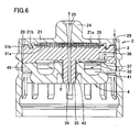
- Fig. 5 is an exploded cross section of the cap, intermediate member and internal stopper in structure and Fig. 6 is a cross section of the cap, intermediate member and internal stopper assembled together.
- tube 35 passes through fit hole 44 of internal stopper 4.
- tube 35 has its upper and intermediate portions larger in diameter than its lower portion.
- Tube 35 has the radially larger portion fitted into fit hole 44 of internal stopper 4.
- Tube 35 is thus positioned in internal stopper 4 at a predetermined position.
- tube 35 has its tip's radially smaller portion intimately contacting an inner circumferential surface of annular valve 42 of internal stopper 4 to configure the check valve.
- tube 35 and internal stopper 4 have been positioned precisely. This ensures that tube 35 is positioned at a predetermined position relative to annular valve 42, and hence that a check valve having a desired performance is obtained.
- check valve can be configured simply by passing tube 35 through annular valve 42.
- a check valve can thus be configured that dispenses with a cutting, as a conventional check valve requires, and readily and reliably operates.
- the check valve is configured such that when the container's main unit 1 has an internal pressure lower than the atmospheric pressure by 5 KPa or larger, annular valve 42 opens outward to form a gap between annular valve 42 and tube 35 to remove a hermetically sealed state to pass air proceeding through air delivering path 43 toward the interior of the container's main unit 1. This is based on that the container's main unit 1 pressed with fingers and thus deformed recovers its original form in geometry with a force, which generates a negative pressure of 5 KPa to 30 KPa in the interior of the container's main unit 1.
- the check valve may be any such valve that when the container's main unit 1 has even a smallest negative pressure therein the valve introduces air received through air delivering path 43 and prevents a flow back to air delivering path 43.
- a check valve is preferably used that opens for a negative pressure slightly smaller than that caused by the container's main unit 1. If the container recovering from a deformed state to its original form in geometry causes a large negative pressure in the interior of the container's main unit 1, the check valve may be adapted to open for an increased pressure.
- the pressure can be set at a variety of values by changing the annular valve in material, geometry, and the like.
- nozzle cap 6 is removed. Then, the container's main unit 1 is pressed with hands/fingers to discharge a liquid agent contained therein. The contained liquid agent is pushed out of the interior of the container, passes through liquid agent introducing path 34, hydrophilic filter 29 and liquid agent discharging path 25, and drops externally through nozzle 24.
- the check valve configured of annular valve 42 and tube 35 is closed, and the liquid agent will not enter air delivering path 43. As such, the liquid agent also will not contact hydrophobic filter 37. As such, if the liquid agent is bad in chemistry with the material(s) of hydrophobic filter 37, hydrophobic filter 37 can be prevented from degradation (e.g., having hydrophilic property), and hydrophobic filter 37 can be prevented from having a lower surface with the liquid agent precipitated thereon.
- the liquid agent is dropped by a required amount and thereafter when pressing the container's main unit 1 is ceased, the container's main unit 1 swells, as based on its flexibility, to recover its original form in geometry. At the time, the container's main unit 1 has negative pressure therein. By this negative pressure, the liquid agent that is retained in the nozzle hole after discharging the liquid agent is stopped will be passed through hydrophilic filter 29 and thus returned to the container's main unit 1.
- the liquid agent retained in the nozzle hole returns through hydrophilic filter 29 to the interior of the container's main unit 1. If the liquid agent retained in the nozzle hole has bacteria or the like mixed therein, the bacteria are filtered off by hydrophilic filter 29.
- the container's main unit 1 has negative pressure therein, and the check valve slightly opens.
- the container's main unit 1 receives air flowing thereinto through air introducing path 28, air supplying path 36, hydrophobic filter 37 and air delivering path 43.
- the check valve limits the introduced air in flow rate. Accordingly, the introduced air enters the interior of the container's main unit 1 gradually, and accordingly, the container's main unit 1 also recovers its original form in geometry slowly over time. In other words, the liquid agent on hydrophilic filter 29 can be recovered into the container's main unit 1 over a sufficient period of time.
- the liquid agent is thus passed by the negative pressure internal to the container's main unit 1 through hydrophilic filter 29 over a sufficient period of time, and nozzle 24 can be prevented from having the liquid agent retained therein.
- nozzle 24 has the liquid agent retained therein for a long period of time, bacteria and the like increases in that retained liquid agent, and when the liquid agent is subsequently used, the bacteria and the like can be mixed in the liquid agent.
- the liquid agent container in the present embodiment can prevent such disadvantage.
- the container's main unit 1 can receive air flowing thereinto that has passed through hydrophobic filter 37 and thus had bacteria, microorganism and the like filtered off.
- the container's main unit 1 can thus have its interior maintained aseptically.
- Such hydrophilic and hydrophobic filters have holes having a diameter preferably of 0.45 ⁇ m or less, more preferably 0.22 ⁇ m or less in order to prevent Candida albicans, the Pseudomonas genus, Burkholderia cepacia and the like generally known as contamination-causing bacteria from entering the interior of the container.
- the filter's capturing mechanism is generally categorized into two types, i.e., a "depth type” capturing bacteria and the like in the filter and a “screen type” capturing bacteria and the like at a surface of the filter. Any of the types can suitably be used in the present invention.
- the liquid agent container in the present embodiment includes cap 2 having hydrophilic filter 29 attached thereto, and intermediate member 3 having hydrophobic filter 37 attached thereto.
- the two filters are not attached to a single member. Rather, they are attached to different members, respectively.
- hydrophobic and hydrophilic filters are attached to a single member at opposite surfaces, which requires inverting the member.
- the present liquid agent container can dispense with inverting the member and thus facilitate attaching the filters.
- the present liquid agent container is remarkably effective when it is used as a container for a chemical agent required to be more aseptic than cosmetics, inter alia, an instillation container that is used to store instillation having a preservative added in a limited amount.
- the present invention can thus provide a liquid agent container including a check valve that can be readily fabricated and ensures preventing a liquid agent from flowing back.
Landscapes
- Health & Medical Sciences (AREA)
- Engineering & Computer Science (AREA)
- Mechanical Engineering (AREA)
- Veterinary Medicine (AREA)
- Pharmacology & Pharmacy (AREA)
- Life Sciences & Earth Sciences (AREA)
- Animal Behavior & Ethology (AREA)
- General Health & Medical Sciences (AREA)
- Public Health (AREA)
- Hematology (AREA)
- Closures For Containers (AREA)
- Medical Preparation Storing Or Oral Administration Devices (AREA)
- Catching Or Destruction (AREA)
- Devices For Use In Laboratory Experiments (AREA)
- Containers And Packaging Bodies Having A Special Means To Remove Contents (AREA)
Applications Claiming Priority (2)
| Application Number | Priority Date | Filing Date | Title |
|---|---|---|---|
| JP2006318718A JP4869039B2 (ja) | 2006-11-27 | 2006-11-27 | 薬液容器 |
| PCT/JP2007/071982 WO2008065879A1 (fr) | 2006-11-27 | 2007-11-13 | Conteneur de liquide chimique |
Publications (3)
| Publication Number | Publication Date |
|---|---|
| EP2090277A1 EP2090277A1 (en) | 2009-08-19 |
| EP2090277A4 EP2090277A4 (en) | 2010-03-10 |
| EP2090277B1 true EP2090277B1 (en) | 2011-05-11 |
Family
ID=39467674
Family Applications (1)
| Application Number | Title | Priority Date | Filing Date |
|---|---|---|---|
| EP07831712A Active EP2090277B1 (en) | 2006-11-27 | 2007-11-13 | Liquid agent container |
Country Status (9)
| Country | Link |
|---|---|
| US (1) | US9308150B2 (ko) |
| EP (1) | EP2090277B1 (ko) |
| JP (1) | JP4869039B2 (ko) |
| KR (1) | KR101387773B1 (ko) |
| CN (1) | CN101541292B (ko) |
| AT (1) | ATE508724T1 (ko) |
| ES (1) | ES2365767T3 (ko) |
| HK (1) | HK1137136A1 (ko) |
| WO (1) | WO2008065879A1 (ko) |
Families Citing this family (33)
| Publication number | Priority date | Publication date | Assignee | Title |
|---|---|---|---|---|
| JP4869039B2 (ja) * | 2006-11-27 | 2012-02-01 | ニプロ株式会社 | 薬液容器 |
| US20100175850A1 (en) * | 2009-01-09 | 2010-07-15 | Kaucic Edward M | Relief Vent for a Hot Fill Fluid Container |
| JP5277047B2 (ja) * | 2009-03-31 | 2013-08-28 | 本田技研工業株式会社 | エンジンの可変動弁装置 |
| US10577158B2 (en) * | 2010-01-29 | 2020-03-03 | Graham Packaging Company, L.P. | Pressure equalizing closure |
| EP2361599A1 (de) * | 2010-02-22 | 2011-08-31 | Fresenius Kabi Deutschland GmbH | Vorrichtung zum Zuführen oder Entnehmen einer Flüssigkeit in ein oder aus einem Behältnis |
| US10392167B2 (en) | 2010-10-12 | 2019-08-27 | Nalge Nunc International Corporation | Ventable closure with port |
| KR101221314B1 (ko) * | 2010-10-19 | 2013-01-10 | 김준배 | 약액 적하용기 |
| US8991643B2 (en) | 2011-03-29 | 2015-03-31 | Graham Packaging Company, L.P. | Closure for use in hotfill and pasteurization applications |
| CN202022423U (zh) * | 2011-04-07 | 2011-11-02 | 杜斌 | 防泄漏单向阀容器 |
| KR101319927B1 (ko) * | 2011-12-01 | 2013-10-18 | 윤희권 | 유동식 공급용 용기유닛 |
| US20150320638A1 (en) * | 2012-12-21 | 2015-11-12 | Fresenius Kabi Deutschland Gmbh | Milk bottle adapter |
| EP2786802A1 (de) * | 2013-04-03 | 2014-10-08 | Metrohm Ag | Verschluss für einen Behälter |
| KR200470695Y1 (ko) * | 2013-08-14 | 2014-01-15 | 박국서 | 공기 차단형 펌핑 용기 |
| WO2016156897A1 (fr) * | 2015-03-31 | 2016-10-06 | Laboratoires Thea | Dispositif de distribution de liquide hors d'un flacon de conditionnement sterile a membrane bi-fonctionnelle |
| JP6611564B2 (ja) * | 2015-10-30 | 2019-11-27 | キヤノン株式会社 | 液体収納ボトルおよび液体収納ボトルのパッケージ |
| US11122881B2 (en) * | 2015-12-10 | 2021-09-21 | Kobayashi Pharmaceutical Co., Ltd. | Chemical solution supply apparatus and chemical solution supply implement |
| CN105712267B (zh) * | 2016-04-14 | 2018-04-06 | 王景东 | 一种封口及应用其的液体盛装容器 |
| CN106492550A (zh) * | 2016-12-20 | 2017-03-15 | 广东顺德工业设计研究院(广东顺德创新设计研究院) | 化学检测系统 |
| CN106475162A (zh) * | 2016-12-20 | 2017-03-08 | 广东顺德工业设计研究院(广东顺德创新设计研究院) | 溶液输送安全盖及试剂瓶 |
| US10238579B2 (en) * | 2017-02-24 | 2019-03-26 | Compliance Meds Technologies Llc | Customizable modular cap system for use with a plurality of different sized bottles |
| WO2019031665A1 (ko) | 2017-08-11 | 2019-02-14 | 주식회사 엘지생활건강 | 화장품 용기 |
| US20200410444A1 (en) * | 2018-03-01 | 2020-12-31 | 3M Innovative Properties Company | Personal protection equipment identification system |
| FR3080844B1 (fr) | 2018-05-07 | 2020-06-05 | Horus Pharma | Dispositif de conditionnement et distribution d'un produit avec flacon et embout doseur muni d'un filtre |
| CN108685688B (zh) * | 2018-06-12 | 2024-05-17 | 张家港众辉医用塑料科技有限公司 | 三级过滤无菌药液包装 |
| KR101966382B1 (ko) * | 2018-08-17 | 2019-04-08 | 박국서 | 공기 차단형 펌핑 용기의 제조방법 |
| JP7293701B2 (ja) * | 2019-02-08 | 2023-06-20 | 株式会社デンソー | 回転電機 |
| US11452672B2 (en) * | 2019-03-01 | 2022-09-27 | Berry Global, Inc. | Pediatric dosing dispenser |
| WO2020180788A1 (en) | 2019-03-01 | 2020-09-10 | Berry Global, Inc. | Pediatric dosing dispenser |
| WO2020190490A1 (en) | 2019-03-15 | 2020-09-24 | Berry Global, Inc. | Pediatric dosing dispenser |
| CN110200807B (zh) * | 2019-07-06 | 2022-02-01 | 中国人民解放军海军第九七一医院 | 一种防漏液药瓶 |
| BR202020001057U2 (pt) * | 2020-01-17 | 2021-07-27 | Alvaro Augusto Fernandes Filho | Tampa adaptável a bocais de garrafas, com elemento direcionador de fluído através de dispositivo gaseificador, para a carbonatação de líquidos |
| KR102663933B1 (ko) | 2021-12-10 | 2024-05-03 | 서울대학교 산학협력단 | 벤트 기능을 갖는 바이알 |
| US11873146B1 (en) * | 2022-07-21 | 2024-01-16 | Jose Gonzalez | Child safety device for medication dispenser |
Family Cites Families (19)
| Publication number | Priority date | Publication date | Assignee | Title |
|---|---|---|---|---|
| US4513891A (en) * | 1982-04-15 | 1985-04-30 | Sterling Drug Inc. | Spray dispensing container and valve therefor |
| US4736083A (en) * | 1985-02-19 | 1988-04-05 | Savillex Corporation | Microwave heating digestion vessel |
| JPS62127063A (ja) | 1985-11-27 | 1987-06-09 | ト−メ−産業株式会社 | 点眼容器 |
| US5320254A (en) * | 1988-10-07 | 1994-06-14 | Ryder International Corp. | Liquid dispenser nozzle assembly |
| DE4015480A1 (de) * | 1990-05-14 | 1991-11-21 | Perfect Ventil Gmbh | Verschlusskappe |
| EP0812625A3 (en) * | 1992-11-11 | 1998-01-14 | Tee Enterprises Limited | A carrier for a pump type atomiser |
| EP0631770B1 (en) * | 1993-06-25 | 1998-07-22 | Alcon Cusi, S.A. | New use of polymeric membranes in the dispensing of pharmaceutical solutions that contain quaternary ammonium compounds as preservatives and corresponding dose dispensor |
| US5490938A (en) * | 1993-12-20 | 1996-02-13 | Biopolymerix, Inc. | Liquid dispenser for sterile solutions |
| GB9717595D0 (en) * | 1997-08-21 | 1997-10-22 | Metal Box Plc | Valves for packaging containers |
| US5988448A (en) * | 1997-09-18 | 1999-11-23 | Foth; Gary S. | Vacuum release container cap |
| JP4580524B2 (ja) * | 2000-09-12 | 2010-11-17 | 株式会社日本点眼薬研究所 | フィルター付き吐出容器 |
| US6631823B2 (en) * | 2001-03-05 | 2003-10-14 | Acorn Bay, Llc | Drink spout system |
| JP4749572B2 (ja) * | 2001-03-13 | 2011-08-17 | 大成化工株式会社 | 分与容器の口栓構造 |
| JP4744775B2 (ja) * | 2002-11-20 | 2011-08-10 | ニプロ株式会社 | 薬液容器 |
| ES2400177T3 (es) * | 2002-04-04 | 2013-04-08 | Nipro Corporation | Contenedor para medicamentos líquidos |
| CN101589939B (zh) * | 2002-09-09 | 2011-08-03 | 宝洁公司 | 流体输送机构 |
| WO2004096113A2 (en) * | 2003-04-28 | 2004-11-11 | Medical Instill Technologies, Inc. | Container with valve assembly for filling and dispensing substances, and apparatus and method for filling |
| US6874656B2 (en) * | 2003-06-04 | 2005-04-05 | Rieke Corporation | Vented closure |
| JP4869039B2 (ja) * | 2006-11-27 | 2012-02-01 | ニプロ株式会社 | 薬液容器 |
-
2006
- 2006-11-27 JP JP2006318718A patent/JP4869039B2/ja active Active
-
2007
- 2007-11-13 KR KR1020097012544A patent/KR101387773B1/ko active IP Right Grant
- 2007-11-13 CN CN2007800439318A patent/CN101541292B/zh active Active
- 2007-11-13 AT AT07831712T patent/ATE508724T1/de not_active IP Right Cessation
- 2007-11-13 US US12/516,322 patent/US9308150B2/en active Active
- 2007-11-13 ES ES07831712T patent/ES2365767T3/es active Active
- 2007-11-13 WO PCT/JP2007/071982 patent/WO2008065879A1/ja active Application Filing
- 2007-11-13 EP EP07831712A patent/EP2090277B1/en active Active
-
2010
- 2010-01-25 HK HK10100777.7A patent/HK1137136A1/xx unknown
Also Published As
| Publication number | Publication date |
|---|---|
| KR101387773B1 (ko) | 2014-04-21 |
| JP4869039B2 (ja) | 2012-02-01 |
| EP2090277A1 (en) | 2009-08-19 |
| CN101541292B (zh) | 2012-10-03 |
| US9308150B2 (en) | 2016-04-12 |
| CN101541292A (zh) | 2009-09-23 |
| ES2365767T3 (es) | 2011-10-10 |
| ATE508724T1 (de) | 2011-05-15 |
| JP2008132013A (ja) | 2008-06-12 |
| US20100084397A1 (en) | 2010-04-08 |
| HK1137136A1 (en) | 2010-07-23 |
| EP2090277A4 (en) | 2010-03-10 |
| WO2008065879A1 (fr) | 2008-06-05 |
| KR20090086256A (ko) | 2009-08-11 |
Similar Documents
| Publication | Publication Date | Title |
|---|---|---|
| EP2090277B1 (en) | Liquid agent container | |
| US6631823B2 (en) | Drink spout system | |
| JP3701026B2 (ja) | 封印された容器を突き破るための制御されたオリフィスライナ付きねじ合わせぶた | |
| US6629624B2 (en) | Drink spout system | |
| AU637590B2 (en) | Enteral bottle cap with vent valve | |
| CN1243220C (zh) | 流体分配阀及使用方法 | |
| US8490839B2 (en) | Filtering dispenser container | |
| JP4448446B2 (ja) | バイアルのクロージャ・システム、バイアル、バイアルの密閉及び充填方法、並びにバイアル・スタンド | |
| US20060180613A1 (en) | Multi-dose liquid dispensing assembly | |
| US8087523B2 (en) | Closure assembly | |
| AU2004270543A1 (en) | Discharge member, discharge container having the discharge member, and instillation container | |
| WO2013168244A1 (ja) | 液体容器の口栓 | |
| EP1087902A1 (en) | Dispensing structure with valve and barrier penetrator | |
| US11013662B2 (en) | Connector system comprising at least two withdrawal ports | |
| JP4744775B2 (ja) | 薬液容器 | |
| US20160199262A1 (en) | Bottle Teat | |
| JP4405775B2 (ja) | フィルター付き吐出容器 | |
| US20060079851A1 (en) | Multipurpose eye dropper and fountain device | |
| JP6336512B2 (ja) | キャップ付き容器 | |
| JP2000109115A (ja) | 医薬品容器用プラスチック製キャップ | |
| CZ294054B6 (cs) | Zátka | |
| MXPA00007925A (en) | Dispensing structure with valve and barrier penetrator |
Legal Events
| Date | Code | Title | Description |
|---|---|---|---|
| PUAI | Public reference made under article 153(3) epc to a published international application that has entered the european phase |
Free format text: ORIGINAL CODE: 0009012 |
|
| 17P | Request for examination filed |
Effective date: 20090624 |
|
| AK | Designated contracting states |
Kind code of ref document: A1 Designated state(s): AT BE BG CH CY CZ DE DK EE ES FI FR GB GR HU IE IS IT LI LT LU LV MC MT NL PL PT RO SE SI SK TR |
|
| DAX | Request for extension of the european patent (deleted) | ||
| A4 | Supplementary search report drawn up and despatched |
Effective date: 20100210 |
|
| GRAP | Despatch of communication of intention to grant a patent |
Free format text: ORIGINAL CODE: EPIDOSNIGR1 |
|
| RIC1 | Information provided on ipc code assigned before grant |
Ipc: B65D 51/16 20060101ALI20100929BHEP Ipc: A61J 1/10 20060101AFI20100929BHEP Ipc: A61J 1/05 20060101ALI20100929BHEP Ipc: B65D 47/18 20060101ALI20100929BHEP Ipc: A61J 1/20 20060101ALN20100929BHEP |
|
| RTI1 | Title (correction) |
Free format text: LIQUID AGENT CONTAINER |
|
| GRAS | Grant fee paid |
Free format text: ORIGINAL CODE: EPIDOSNIGR3 |
|
| GRAA | (expected) grant |
Free format text: ORIGINAL CODE: 0009210 |
|
| RAP1 | Party data changed (applicant data changed or rights of an application transferred) |
Owner name: NIPRO CORPORATION Owner name: WAKAMOTO PHARMACEUTICAL CO., LTD. |
|
| AK | Designated contracting states |
Kind code of ref document: B1 Designated state(s): AT BE BG CH CY CZ DE DK EE ES FI FR GB GR HU IE IS IT LI LT LU LV MC MT NL PL PT RO SE SI SK TR |
|
| REG | Reference to a national code |
Ref country code: GB Ref legal event code: FG4D |
|
| REG | Reference to a national code |
Ref country code: CH Ref legal event code: EP |
|
| REG | Reference to a national code |
Ref country code: IE Ref legal event code: FG4D |
|
| REG | Reference to a national code |
Ref country code: DE Ref legal event code: R096 Ref document number: 602007014573 Country of ref document: DE Effective date: 20110622 |
|
| REG | Reference to a national code |
Ref country code: CH Ref legal event code: NV Representative=s name: R. A. EGLI & CO. PATENTANWAELTE |
|
| REG | Reference to a national code |
Ref country code: NL Ref legal event code: VDEP Effective date: 20110511 |
|
| REG | Reference to a national code |
Ref country code: ES Ref legal event code: FG2A Ref document number: 2365767 Country of ref document: ES Kind code of ref document: T3 Effective date: 20111010 |
|
| PG25 | Lapsed in a contracting state [announced via postgrant information from national office to epo] |
Ref country code: LT Free format text: LAPSE BECAUSE OF FAILURE TO SUBMIT A TRANSLATION OF THE DESCRIPTION OR TO PAY THE FEE WITHIN THE PRESCRIBED TIME-LIMIT Effective date: 20110511 Ref country code: SE Free format text: LAPSE BECAUSE OF FAILURE TO SUBMIT A TRANSLATION OF THE DESCRIPTION OR TO PAY THE FEE WITHIN THE PRESCRIBED TIME-LIMIT Effective date: 20110511 Ref country code: PT Free format text: LAPSE BECAUSE OF FAILURE TO SUBMIT A TRANSLATION OF THE DESCRIPTION OR TO PAY THE FEE WITHIN THE PRESCRIBED TIME-LIMIT Effective date: 20110912 |
|
| PG25 | Lapsed in a contracting state [announced via postgrant information from national office to epo] |
Ref country code: IS Free format text: LAPSE BECAUSE OF FAILURE TO SUBMIT A TRANSLATION OF THE DESCRIPTION OR TO PAY THE FEE WITHIN THE PRESCRIBED TIME-LIMIT Effective date: 20110911 Ref country code: LV Free format text: LAPSE BECAUSE OF FAILURE TO SUBMIT A TRANSLATION OF THE DESCRIPTION OR TO PAY THE FEE WITHIN THE PRESCRIBED TIME-LIMIT Effective date: 20110511 Ref country code: SI Free format text: LAPSE BECAUSE OF FAILURE TO SUBMIT A TRANSLATION OF THE DESCRIPTION OR TO PAY THE FEE WITHIN THE PRESCRIBED TIME-LIMIT Effective date: 20110511 Ref country code: CY Free format text: LAPSE BECAUSE OF FAILURE TO SUBMIT A TRANSLATION OF THE DESCRIPTION OR TO PAY THE FEE WITHIN THE PRESCRIBED TIME-LIMIT Effective date: 20110511 Ref country code: GR Free format text: LAPSE BECAUSE OF FAILURE TO SUBMIT A TRANSLATION OF THE DESCRIPTION OR TO PAY THE FEE WITHIN THE PRESCRIBED TIME-LIMIT Effective date: 20110812 Ref country code: AT Free format text: LAPSE BECAUSE OF FAILURE TO SUBMIT A TRANSLATION OF THE DESCRIPTION OR TO PAY THE FEE WITHIN THE PRESCRIBED TIME-LIMIT Effective date: 20110511 Ref country code: FI Free format text: LAPSE BECAUSE OF FAILURE TO SUBMIT A TRANSLATION OF THE DESCRIPTION OR TO PAY THE FEE WITHIN THE PRESCRIBED TIME-LIMIT Effective date: 20110511 Ref country code: BE Free format text: LAPSE BECAUSE OF FAILURE TO SUBMIT A TRANSLATION OF THE DESCRIPTION OR TO PAY THE FEE WITHIN THE PRESCRIBED TIME-LIMIT Effective date: 20110511 |
|
| PG25 | Lapsed in a contracting state [announced via postgrant information from national office to epo] |
Ref country code: NL Free format text: LAPSE BECAUSE OF FAILURE TO SUBMIT A TRANSLATION OF THE DESCRIPTION OR TO PAY THE FEE WITHIN THE PRESCRIBED TIME-LIMIT Effective date: 20110511 |
|
| PG25 | Lapsed in a contracting state [announced via postgrant information from national office to epo] |
Ref country code: EE Free format text: LAPSE BECAUSE OF FAILURE TO SUBMIT A TRANSLATION OF THE DESCRIPTION OR TO PAY THE FEE WITHIN THE PRESCRIBED TIME-LIMIT Effective date: 20110511 Ref country code: CZ Free format text: LAPSE BECAUSE OF FAILURE TO SUBMIT A TRANSLATION OF THE DESCRIPTION OR TO PAY THE FEE WITHIN THE PRESCRIBED TIME-LIMIT Effective date: 20110511 |
|
| PG25 | Lapsed in a contracting state [announced via postgrant information from national office to epo] |
Ref country code: PL Free format text: LAPSE BECAUSE OF FAILURE TO SUBMIT A TRANSLATION OF THE DESCRIPTION OR TO PAY THE FEE WITHIN THE PRESCRIBED TIME-LIMIT Effective date: 20110511 Ref country code: RO Free format text: LAPSE BECAUSE OF FAILURE TO SUBMIT A TRANSLATION OF THE DESCRIPTION OR TO PAY THE FEE WITHIN THE PRESCRIBED TIME-LIMIT Effective date: 20110511 Ref country code: SK Free format text: LAPSE BECAUSE OF FAILURE TO SUBMIT A TRANSLATION OF THE DESCRIPTION OR TO PAY THE FEE WITHIN THE PRESCRIBED TIME-LIMIT Effective date: 20110511 Ref country code: DK Free format text: LAPSE BECAUSE OF FAILURE TO SUBMIT A TRANSLATION OF THE DESCRIPTION OR TO PAY THE FEE WITHIN THE PRESCRIBED TIME-LIMIT Effective date: 20110511 |
|
| PLBE | No opposition filed within time limit |
Free format text: ORIGINAL CODE: 0009261 |
|
| STAA | Information on the status of an ep patent application or granted ep patent |
Free format text: STATUS: NO OPPOSITION FILED WITHIN TIME LIMIT |
|
| 26N | No opposition filed |
Effective date: 20120214 |
|
| REG | Reference to a national code |
Ref country code: DE Ref legal event code: R097 Ref document number: 602007014573 Country of ref document: DE Effective date: 20120214 |
|
| PG25 | Lapsed in a contracting state [announced via postgrant information from national office to epo] |
Ref country code: MC Free format text: LAPSE BECAUSE OF NON-PAYMENT OF DUE FEES Effective date: 20111130 |
|
| REG | Reference to a national code |
Ref country code: IE Ref legal event code: MM4A |
|
| PG25 | Lapsed in a contracting state [announced via postgrant information from national office to epo] |
Ref country code: IE Free format text: LAPSE BECAUSE OF NON-PAYMENT OF DUE FEES Effective date: 20111113 |
|
| PG25 | Lapsed in a contracting state [announced via postgrant information from national office to epo] |
Ref country code: MT Free format text: LAPSE BECAUSE OF FAILURE TO SUBMIT A TRANSLATION OF THE DESCRIPTION OR TO PAY THE FEE WITHIN THE PRESCRIBED TIME-LIMIT Effective date: 20110511 |
|
| PG25 | Lapsed in a contracting state [announced via postgrant information from national office to epo] |
Ref country code: LU Free format text: LAPSE BECAUSE OF NON-PAYMENT OF DUE FEES Effective date: 20111113 |
|
| PG25 | Lapsed in a contracting state [announced via postgrant information from national office to epo] |
Ref country code: BG Free format text: LAPSE BECAUSE OF FAILURE TO SUBMIT A TRANSLATION OF THE DESCRIPTION OR TO PAY THE FEE WITHIN THE PRESCRIBED TIME-LIMIT Effective date: 20110811 |
|
| PG25 | Lapsed in a contracting state [announced via postgrant information from national office to epo] |
Ref country code: TR Free format text: LAPSE BECAUSE OF FAILURE TO SUBMIT A TRANSLATION OF THE DESCRIPTION OR TO PAY THE FEE WITHIN THE PRESCRIBED TIME-LIMIT Effective date: 20110511 |
|
| PG25 | Lapsed in a contracting state [announced via postgrant information from national office to epo] |
Ref country code: HU Free format text: LAPSE BECAUSE OF FAILURE TO SUBMIT A TRANSLATION OF THE DESCRIPTION OR TO PAY THE FEE WITHIN THE PRESCRIBED TIME-LIMIT Effective date: 20110511 |
|
| REG | Reference to a national code |
Ref country code: FR Ref legal event code: PLFP Year of fee payment: 9 |
|
| REG | Reference to a national code |
Ref country code: FR Ref legal event code: PLFP Year of fee payment: 10 |
|
| REG | Reference to a national code |
Ref country code: FR Ref legal event code: PLFP Year of fee payment: 11 |
|
| REG | Reference to a national code |
Ref country code: DE Ref legal event code: R082 Ref document number: 602007014573 Country of ref document: DE Representative=s name: PRUEFER & PARTNER MBB PATENTANWAELTE RECHTSANW, DE Ref country code: DE Ref legal event code: R081 Ref document number: 602007014573 Country of ref document: DE Owner name: NIPRO CORP., OSAKA-SHI, JP Free format text: FORMER OWNERS: NIPRO CORP., OSAKA-SHI, OSAKA, JP; WAKAMOTO PHARMACEUTICAL CO., LTD., TOKIO/TOKYO, JP |
|
| REG | Reference to a national code |
Ref country code: CH Ref legal event code: PUEA Owner name: NIPRO CORPORATION, JP Free format text: FORMER OWNER: NIPRO CORPORATION, JP |
|
| REG | Reference to a national code |
Ref country code: GB Ref legal event code: 732E Free format text: REGISTERED BETWEEN 20210204 AND 20210210 |
|
| REG | Reference to a national code |
Ref country code: ES Ref legal event code: PC2A Owner name: NIPRO CORPORATION Effective date: 20210303 |
|
| PGFP | Annual fee paid to national office [announced via postgrant information from national office to epo] |
Ref country code: GB Payment date: 20231123 Year of fee payment: 17 |
|
| PGFP | Annual fee paid to national office [announced via postgrant information from national office to epo] |
Ref country code: ES Payment date: 20231215 Year of fee payment: 17 |
|
| PGFP | Annual fee paid to national office [announced via postgrant information from national office to epo] |
Ref country code: IT Payment date: 20231130 Year of fee payment: 17 Ref country code: FR Payment date: 20231124 Year of fee payment: 17 Ref country code: DE Payment date: 20231128 Year of fee payment: 17 Ref country code: CH Payment date: 20231202 Year of fee payment: 17 |