EP2089848B1 - Noise reduction of panchromatic and color image - Google Patents
Noise reduction of panchromatic and color image Download PDFInfo
- Publication number
- EP2089848B1 EP2089848B1 EP07852989A EP07852989A EP2089848B1 EP 2089848 B1 EP2089848 B1 EP 2089848B1 EP 07852989 A EP07852989 A EP 07852989A EP 07852989 A EP07852989 A EP 07852989A EP 2089848 B1 EP2089848 B1 EP 2089848B1
- Authority
- EP
- European Patent Office
- Prior art keywords
- image
- panchromatic
- color
- noise
- full
- Prior art date
- Legal status (The legal status is an assumption and is not a legal conclusion. Google has not performed a legal analysis and makes no representation as to the accuracy of the status listed.)
- Active
Links
- 230000009467 reduction Effects 0.000 title claims description 32
- 238000004519 manufacturing process Methods 0.000 claims abstract 2
- 238000000034 method Methods 0.000 claims description 19
- 238000012545 processing Methods 0.000 description 23
- 230000003044 adaptive effect Effects 0.000 description 9
- 238000000354 decomposition reaction Methods 0.000 description 8
- 238000010586 diagram Methods 0.000 description 8
- 238000013459 approach Methods 0.000 description 6
- 238000001514 detection method Methods 0.000 description 5
- 238000001914 filtration Methods 0.000 description 4
- 238000004140 cleaning Methods 0.000 description 3
- 230000003287 optical effect Effects 0.000 description 3
- 230000000007 visual effect Effects 0.000 description 3
- 238000004891 communication Methods 0.000 description 2
- 238000004590 computer program Methods 0.000 description 2
- 230000014509 gene expression Effects 0.000 description 2
- 230000004044 response Effects 0.000 description 2
- 230000035945 sensitivity Effects 0.000 description 2
- 206010034960 Photophobia Diseases 0.000 description 1
- 230000008901 benefit Effects 0.000 description 1
- 230000008859 change Effects 0.000 description 1
- 230000001419 dependent effect Effects 0.000 description 1
- 230000006870 function Effects 0.000 description 1
- 238000005286 illumination Methods 0.000 description 1
- 208000013469 light sensitivity Diseases 0.000 description 1
- 239000000463 material Substances 0.000 description 1
- 238000005259 measurement Methods 0.000 description 1
- 238000003032 molecular docking Methods 0.000 description 1
- 238000012552 review Methods 0.000 description 1
- 229910052709 silver Inorganic materials 0.000 description 1
- 239000004332 silver Substances 0.000 description 1
- -1 silver halide Chemical class 0.000 description 1
- 239000007787 solid Substances 0.000 description 1
Images


Classifications
-
- G—PHYSICS
- G06—COMPUTING; CALCULATING OR COUNTING
- G06T—IMAGE DATA PROCESSING OR GENERATION, IN GENERAL
- G06T3/00—Geometric image transformation in the plane of the image
- G06T3/40—Scaling the whole image or part thereof
- G06T3/4015—Demosaicing, e.g. colour filter array [CFA], Bayer pattern
-
- G—PHYSICS
- G06—COMPUTING; CALCULATING OR COUNTING
- G06T—IMAGE DATA PROCESSING OR GENERATION, IN GENERAL
- G06T5/00—Image enhancement or restoration
- G06T5/20—Image enhancement or restoration by the use of local operators
-
- G—PHYSICS
- G06—COMPUTING; CALCULATING OR COUNTING
- G06T—IMAGE DATA PROCESSING OR GENERATION, IN GENERAL
- G06T5/00—Image enhancement or restoration
- G06T5/50—Image enhancement or restoration by the use of more than one image, e.g. averaging, subtraction
-
- G06T5/70—
-
- G—PHYSICS
- G06—COMPUTING; CALCULATING OR COUNTING
- G06T—IMAGE DATA PROCESSING OR GENERATION, IN GENERAL
- G06T2207/00—Indexing scheme for image analysis or image enhancement
- G06T2207/10—Image acquisition modality
- G06T2207/10024—Color image
Definitions
- the invention relates generally to the field of digital image processing operations that produce a full-color noise-reduced full-resolution image from an image having panchromatic and color pixels.
- noise reduction is especially true for digital still and video camera images that may have been captured under insufficient lighting conditions.
- One way to address digital image capture under less than optimum lighting conditions is to either acquire or synthesize one or more color channels that are particularly sensitive to low or insufficient scene illumination.
- the data from the channels with increased light sensitivity are generally used to guide the subsequent image processing of the data from the accompanying standard color channels.
- Noise reduction is a prime candidate for benefiting from this additional image data.
- EP 1 241 896 discloses an image sensing device with different color types of photosites and a method of capturing a color digital image by interpolating pixels values to remedy an overexposure condition.
- EP 0 472 299 discloses an image signal processing apparatus having an image picup device and a color filter arranged as a Bayer type filter.
- EP 1 209 903 discloses a system and more specifically a method of noise removal for a sparsely sampled extended dynamic range image.
- U.S. Patent No. 6,646,246 (Gindele, et al. ) teaches using an extended dynamic range color filter array (CFA) pattern with slow and fast pixels, noise-cleaning the slow pixel data using only slow pixel data and noise-cleaning the fast pixel data using only fast pixel data.
- CFA color filter array
- a luminance signal is representative of a fair number of similarly disclosed inventions in that it reveals constructing a luminance signal from directly sensed color channel data, in this case cyan, magenta, yellow, and green.
- the high-frequency component of the constructed luminance is used to replace the high-frequency component of the original color channel signals to affect a net noise reduction of the image data.
- the major liability of this approach is that the synthesized luminance channel is constructed from noisy color channel components resulting in an essentially equally noisy synthetic channel.
- Cok discloses direct measurement of red, green, blue, and luminance values at each pixel location.
- the high-frequency luminance data which is designed to be inherently less noisy than the corresponding high-frequency red, green, and blue data is used to replace said high-frequency red, green, and blue data to produce noise-cleaned red, green, and blue signals. Since the vast majority of digital still and video cameras use a single sensor equipped with a CFA that only senses one color channel per pixel, Cok cannot be directly practiced in such systems.
- Xiaomang and Cok describe luminance signals
- a color channel with photometric sensitivity conforming to the luminance channel of the human visual system is unnecessarily restrictive.
- a more useful signal can be captured with a more general panchromatic channel, which has higher sensitivity at all wavelengths over the luminance channel of the human visual system.
- Specific embodiments of the invention are defined in the dependent claims.
- images can be captured under low-light conditions with a sensor having panchromatic and color pixels and processing reduces noise in a full-color image produced from the panchromatic and colored pixels.
- the computer program can be stored in a computer readable storage medium, which can comprise, for example; magnetic storage media such as a magnetic disk (such as a hard drive or a floppy disk) or magnetic tape; optical storage media such as an optical disc, optical tape, or machine readable bar code; solid state electronic storage devices such as random access memory (RAM), or read only memory (ROM); or any other physical device or medium employed to store a computer program.
- a computer readable storage medium can comprise, for example; magnetic storage media such as a magnetic disk (such as a hard drive or a floppy disk) or magnetic tape; optical storage media such as an optical disc, optical tape, or machine readable bar code; solid state electronic storage devices such as random access memory (RAM), or read only memory (ROM); or any other physical device or medium employed to store a computer program.
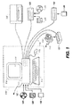
- the present invention is preferably utilized on any well-known computer system, such a personal computer. Consequently, the computer system will not be discussed in detail herein. It is also instructive to note that the images are either directly input into the computer system (for example by a digital camera) or digitized before input into the computer system (for example by scanning an original, such as a silver halide film).
- the computer system 110 includes a microprocessor-based unit 112 for receiving and processing software programs and for performing other processing functions.
- a display 114 is electrically connected to the microprocessor-based unit 112 for displaying user-related information associated with the software, e.g., by a graphical user interface.
- a keyboard 116 is also connected to the microprocessor based unit 112 for permitting a user to input information to the software.
- a mouse 118 can be used for moving a selector 120 on the display 114 and for selecting an item on which the selector 120 overlays, as is well known in the art.
- a compact disk-read only memory (CD-ROM) 124 which typically includes software programs, is inserted into the microprocessor based unit for providing a way of inputting the software programs and other information to the microprocessor based unit 112.
- a floppy disk 126 can also include a software program, and is inserted into the microprocessor-based unit 112 for inputting the software program.
- the compact disk-read only memory (CD-ROM) 124 or a floppy disk 126 can alternatively be inserted into an externally located disk drive unit 122 which is connected to the microprocessor-based unit 112.
- the microprocessor-based unit 112 can be programmed, as is well known in the art, for storing the software program internally.
- the microprocessor-based unit 112 can also have a network connection 127, such as a telephone line, to an external network, such as a local area network or the Internet.
- a printer 128 can also be connected to the microprocessor-based unit 112 for printing a hardcopy of the output from the computer system 110.
- Images can also be displayed on the display 114 via a personal computer card (PC card) 130, such as, as it was formerly known, a PCMCIA card (based on the specifications of the Personal Computer Memory Card International Association) which contains digitized images electronically embodied in the PC card 130.
- PC card 130 is ultimately inserted into the microprocessor based unit 112 for permitting visual display of the image on the display 114.
- the PC card 130 can be inserted into an externally located.
- PC card reader 132 connected to the microprocessor-based unit 112. Images can also be input via the compact disk 124, the floppy disk 126, or the network connection 127.
- Any images stored in the PC card 130, the floppy disk 126 or the compact disk 124, or input through the network connection 127, can have been obtained from a variety of sources, such as a digital camera (not shown) or a scanner (not shown). Images can also be input directly from a digital camera 134 via a camera docking port 136 connected to the microprocessor-based unit 112 or directly from the digital camera 134 via a cable connection 138 to the microprocessor-based unit 112 or via a wireless connection 140 to the microprocessor-based unit 112.
- the algorithm can be stored in any of the storage devices heretofore mentioned and applied to images in order to interpolate sparsely populated images.
- FIG. 2 is a high level diagram of a preferred embodiment.
- the digital camera 134 is responsible for creating an original digital red-green-blue-panchromatic (RGBP) color filter array (CFA) image 200, also referred to as the digital RGBP CFA image or the RGBP CFA image.
- RGBBP red-green-blue-panchromatic
- CFA color filter array
- cyan-magenta-yellow-panchromatic can be used in place of red-green-blue-panchromatic in the following description.
- the key item is the inclusion of a panchromatic channel. This image is considered to be a sparsely sampled image because each pixel in the image contains only one pixel value of red, green, blue, or panchromatic data.
- a panchromatic image interpolation block 202 produces a full-resolution panchromatic image 204.
- each color pixel location has an associated panchromatic value and either a red, green, or blue value.
- the noise associated with the red, green, and blue pixel values is now reduced in an RGB CFA image noise reduction block 210 to produce a noise-reduced RGB CFA image 212.
- An RGB CFA image interpolation block 214 subsequently produces a noise-reduced full-resolution full-color image 226.
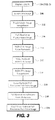
- FIG. 3 is a high level diagram of a second preferred embodiment.
- the digital camera 134 is responsible for creating an original digital red-green-blue-panchromatic (RGBP) color filter array (CFA) image 200, also referred to as the digital RGBP CFA image or the RGBP CFA image.
- RGBBP red-green-blue-panchromatic
- CFA color filter array
- cyan-magenta-yellow-panchromatic can be used in place of red-green-blue-panchromatic in the following description.
- the key item is the inclusion of a panchromatic channel. This image is considered to be a sparsely sampled image because each pixel in the image contains only one pixel value of red, green, blue, or panchromatic data.
- a panchromatic image interpolation block 202 produces a full-resolution panchromatic image 204.
- each color pixel location has an associated panchromatic value and either a red, green, or blue value.
- the noise associated with the red, green, and blue pixel values is now reduced in an RGB CFA image noise reduction block 210 to produce a noise-reduced RGB CFA image 212.
- An RGB CFA image interpolation block 214 subsequently produces a noise-reduced full-resolution full-color image 216.
- a full-resolution full-color noise reduction block 218 produces a final noise-reduced full-resolution full-color image block 224.
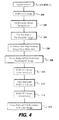
- FIG. 4 is a high level diagram of a preferred embodiment.
- the digital camera 134 is responsible for creating an original digital red-green-blue-panchromatic (RGBP) color filter array (CFA) image 200, also referred to as the digital RGBP CFA image or the RGBP CFA image.
- RGBP red-green-blue-panchromatic
- CFA color filter array
- cyan-magenta-yellow-panchromatic can be used in place of red-green-blue-panchromatic in the following description.
- the key item is the inclusion of a panchromatic channel. This image is considered to be a sparsely sampled image because each pixel in the image contains only one pixel value of red, green, blue, or panchromatic data.
- a panchromatic image interpolation block 202 produces a full-resolution panchromatic image 204.
- each color pixel location has an associated panchromatic value and either a red, green, or blue value.
- a full-resolution panchromatic image noise reduction block 206 produces a noise-reduced full-resolution panchromatic image 208.
- the noise associated with the red, green, and blue pixel values is now reduced in an RGB CFA image noise reduction block 210 to produce a noise-reduced RGB CFA image 212.
- An RGB CFA image interpolation block 214 subsequently produces a noise-reduced full-resolution full-color image 222.
- FIG. 5 is a high level diagram of a preferred embodiment.
- the digital camera 134 is responsible for creating an original digital red-green-blue-panchromatic (RGBP) color filter array (CFA) image 200, also referred to as the digital RGBP CFA image or the RGBP CFA image.
- RGBBP red-green-blue-panchromatic
- CFA color filter array
- cyan-magenta-yellow-panchromatic can be used in place of red-green-blue-panchromatic in the following description.
- the key item is the inclusion of a panchromatic channel. This image is considered to be a sparsely sampled image because each pixel in the image contains only one pixel value of red, green, blue, or panchromatic data.
- a panchromatic image interpolation block 202 produces a full-resolution panchromatic image 204.
- each color pixel location has an associated panchromatic value and either a red, green, or blue value.
- a full-resolution panchromatic image noise reduction block 206 produces a noise-reduced full-resolution panchromatic image 208.
- the noise associated with the red, green, and blue pixel values is now reduced in an RGB CFA image noise reduction block 210 to produce a noise-reduced RGB CFA image 212.
- An RGB CFA image interpolation block 214 subsequently produces a noise-reduced full-resolution full-color image 216.
- a full-resolution full-color noise reduction block 218 produces a final noise-reduced full-resolution full-color image block 220.
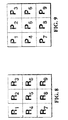
- X 5 P 1 + 2 ⁇ P 2 + P 3 + P 7 + 2 ⁇ P 8 + P 9 / 8
- an adaptive approach can be used by first computing the absolute values of directional gradients (absolute directional gradients).
- B 5 P 1 - P 9
- V 5 P 2 - P 8
- S 5 P 3 - P 7
- the value of X 5 is now determined by one of three two-point averages.
- RGB CFA image noise reduction block 210 is preferably performed in an adaptive manner to take advantage of the full-resolution panchromatic image produced by block 202. Any number of such methods will be known to those skilled in the arts. Two examples are now given. Referring to FIG. 7 , it is to be noted that each pixel location has an associated panchromatic value. It is also noted that the number and placement of intervening non-red pixels (i.e., blank pixels in FIG. 7 ) is irrelevant. All that is required is a central pixel value with at least one or more neighboring pixel values of the same color. Also, in the following discussion, green or blue would be substituted for red when cleaning the green or blue color channels.
- a sigma filter can be used to accomplish noise reduction of the red pixel R 5 . This is accomplished by computing the following weighted average.
- R 5 c 1 ⁇ R 1 + c 2 ⁇ R 2 + c 3 ⁇ R 3 + c 4 ⁇ R 4 + c 5 ⁇ R 5 + c 6 ⁇ R 6 + c 7 ⁇ R 7 + c 8 ⁇ R 8 + c 9 ⁇ R 9 / c 1 + c 2 + c 3 + c 4 + c 5 + c 6 + c 7 + c 8 + c 9
- the weighting coefficients c 1 through c 9 are computed from differences in panchromatic values.
- t is a predetermined threshold value that is chosen to exclude pixel values
- the noise-reduced value for R 5 corresponds to the red median value that corresponds to the panchromatic median value that is closest to panchromatic value associated with R 5 , i.e., P 5 .
- R 5 R H if P H - P 5 ⁇ P B - P 5 P V - P 5 P S - P 5
- R 5 R B if P B - P 5 ⁇ P H - P 5 P V - P 5 P S - P 5
- R 5 R V if P V - P 5 ⁇ P H - P 5 P B - P 5 P S - P 5
- R 5 R S if P S - P 5 ⁇ P H - P 5 P B - P 5 P V - P 5
- Alternate schemes for employing adaptive median filters include those using fewer than four median values within the neighborhood are well known in the art and can be similarly adapted to using full-resolution panchromatic data.
- noise reduction methods such as, but not limited to, infinite impulse response (IIR) filtering and singular value decomposition (SVD) could be used.
- IIR infinite impulse response
- SMD singular value decomposition
- RGB CFA image interpolation block 214 can be performed using any of the well-known CFA interpolation or demosaicking techniques described in the prior art.
- U.S. Patent No. 5,852,468 (Okada ) describes a typical nonadaptive method while U.S. Patent No. 5,506,619 (Adams, et al. ) teaches a representative adaptive approach.
- full-resolution full-color noise reduction block 216 can be performed in a manner similar to the RGB CFA image noise reduction block 210, only in block 216 there are red, green, blue, and panchromatic values at each pixel location. Therefore, noise reduction can be performed using contiguous pixel neighborhoods, such as depicted in FIG. 8 .
- the examples given above of the sigma filter and adaptive median filter are directly applicable.
- full-resolution panchromatic image noise reduction block 206 would be performed using any of the well-known methods in the prior art for grayscale or single-channel image noise reduction. These would include the previously described examples of sigma filtering and adaptive median filtering. Referring to FIG. 9 , a sigma filter can be used to accomplish noise reduction of the panchromatic pixel P 5 . This is accomplished by computing the following weighted average.
- P 5 c 1 ⁇ P 1 + c 2 ⁇ P 2 + c 3 ⁇ P 3 + c 4 ⁇ P 4 + c 5 ⁇ P 5 + c 6 ⁇ P 6 + c 7 ⁇ P 7 + c 8 ⁇ P 8 + c 9 ⁇ P 9 / c 1 + c 2 + c 3 + c 4 + c 5 + c 6 + c 7 + c 8 + c 9
- the weighting coefficients c 1 through c 9 are computed from differences in panchromatic values.
- t is a predetermined threshold value that is chosen to exclude pixel values
- Alternate schemes for employing adaptive median filters are well known in the art and can be used.
- noise reduction methods such as, but not limited to, infinite impulse response (IIR) filtering and singular value decomposition (SVD) could be used.
- IIR infinite impulse response
- SMD singular value decomposition
- exemplary contexts and environments include, without limitation, wholesale digital photofinishing (which involves exemplary process steps or stages such as film in, digital processing, prints out), retail digital photofinishing (film in, digital processing, prints out), home printing (home scanned film or digital images, digital processing, prints out), desktop software (software that applies algorithms to digital prints to make them better -or even just to change them), digital fulfillment (digital images in - from media or over the web, digital processing, with images out - in digital form on media, digital form over the web, or printed on hard-copy prints), kiosks (digital or scanned input, digital processing, digital or scanned output), mobile devices (e.g., PDA or cell phone that can be used as a processing unit, a display unit, or a unit to give processing instructions), and as a service offered via the World Wide Web.
- wholesale digital photofinishing which involves exemplary process steps or stages such as film in, digital processing, prints out
- retail digital photofinishing film in, digital processing, prints out
- home printing home scanned film or digital images
- the noise reduction algorithms can stand alone or can be a component of a larger system solution.
- the interfaces with the algorithm e.g., the scanning or input, the digital processing, the display to a user (if needed), the input of user requests or processing instructions (if needed), the output, can each be on the same or different devices and physical locations, and communication between the devices and locations can be via public or private network connections, or media based communication.
- the algorithms themselves can be fully automatic, can have user input (be fully or partially manual), can have user or operator review to accept/reject the result, or can be assisted by metadata (metadata that can be user supplied, supplied by a measuring device (e.g. in a camera), or determined by an algorithm).
- the algorithms can interface with a variety of workflow user interface schemes.
- the noise reduction algorithms disclosed herein in accordance with the invention can have interior components that utilize various data detection and reduction techniques (e.g., face detection, eye detection, skin detection, flash detection).
- various data detection and reduction techniques e.g., face detection, eye detection, skin detection, flash detection.
Landscapes
- Physics & Mathematics (AREA)
- General Physics & Mathematics (AREA)
- Engineering & Computer Science (AREA)
- Theoretical Computer Science (AREA)
- Image Processing (AREA)
- Color Television Image Signal Generators (AREA)
Abstract
Description
- The invention relates generally to the field of digital image processing operations that produce a full-color noise-reduced full-resolution image from an image having panchromatic and color pixels.
- One of the most common and frequently essential image processing operations is noise reduction. This is especially true for digital still and video camera images that may have been captured under insufficient lighting conditions. One way to address digital image capture under less than optimum lighting conditions is to either acquire or synthesize one or more color channels that are particularly sensitive to low or insufficient scene illumination. The data from the channels with increased light sensitivity are generally used to guide the subsequent image processing of the data from the accompanying standard color channels. Noise reduction is a prime candidate for benefiting from this additional image data. A number of examples exist in the literature.
-
EP 1 241 896 discloses an image sensing device with different color types of photosites and a method of capturing a color digital image by interpolating pixels values to remedy an overexposure condition. -
EP 0 472 299 discloses an image signal processing apparatus having an image picup device and a color filter arranged as a Bayer type filter. -
EP 1 209 903 discloses a system and more specifically a method of noise removal for a sparsely sampled extended dynamic range image. -
U.S. Patent No. 6,646,246 (Gindele, et al. ) teaches using an extended dynamic range color filter array (CFA) pattern with slow and fast pixels, noise-cleaning the slow pixel data using only slow pixel data and noise-cleaning the fast pixel data using only fast pixel data. This approach achieved noise reduction at the expense of image resolution as each color channel is now subdivided into a fast channel and a slow channel and the subsequent merger can produce image processing artifacts more troublesome than the original noise being addressed.U.S. Patent No. 7,065,246 (Xiaomang, et al. ) is representative of a fair number of similarly disclosed inventions in that it reveals constructing a luminance signal from directly sensed color channel data, in this case cyan, magenta, yellow, and green. The high-frequency component of the constructed luminance is used to replace the high-frequency component of the original color channel signals to affect a net noise reduction of the image data. While somewhat effective, the major liability of this approach is that the synthesized luminance channel is constructed from noisy color channel components resulting in an essentially equally noisy synthetic channel. - A suggestion of a better approach can be found in
U.S. Patent No. 5,264,924 (Cok ). Cok discloses direct measurement of red, green, blue, and luminance values at each pixel location. The high-frequency luminance data which is designed to be inherently less noisy than the corresponding high-frequency red, green, and blue data is used to replace said high-frequency red, green, and blue data to produce noise-cleaned red, green, and blue signals. Since the vast majority of digital still and video cameras use a single sensor equipped with a CFA that only senses one color channel per pixel, Cok cannot be directly practiced in such systems. - While Xiaomang and Cok describe luminance signals, a color channel with photometric sensitivity conforming to the luminance channel of the human visual system is unnecessarily restrictive. A more useful signal can be captured with a more general panchromatic channel, which has higher sensitivity at all wavelengths over the luminance channel of the human visual system.
- It is an object of the present invention to produce a noise-reduced full-resolution full-color image from a digital image having panchromatic and color pixels as defined in claim 1. Specific embodiments of the invention are defined in the dependent claims.
- It is a feature of the present invention that images can be captured under low-light conditions with a sensor having panchromatic and color pixels and processing reduces noise in a full-color image produced from the panchromatic and colored pixels.
-
-
FIG. 1 is a perspective of a computer system including a digital camera for implementing the present invention; -
FIG. 2 is a block diagram of a preferred embodiment of the present invention; -
FIG. 3 is a block diagram of an alternate embodiment of the present invention; -
FIG. 4 is a block diagram of an alternate embodiment of the present invention; -
FIG. 5 is a block diagram of an alternate embodiment of the present invention; -
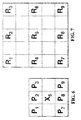
FIG. 6 is a region of pixels used inblock 202 inFIG. 2 ; -
FIG. 7 is a region of pixels used inblock 206 inFIG. 2 ; -
FIG. 8 is a region of pixels used inblock 210 inFIG. 3 ; and -
FIG. 9 is a region of pixels used inblock 204 inFIG. 4 . - In the following description, a preferred embodiment of the present invention will be described in terms that would ordinarily be implemented as a software program. Those skilled in the art will readily recognize that the equivalent of such software can also be constructed in hardware. Because image manipulation algorithms and systems are well known, the present description will be directed in particular to algorithms and systems forming part of, or cooperating more directly with, the system and method in accordance with the present invention. Other aspects of such algorithms and systems, and hardware or software for producing and otherwise processing the image signals involved therewith, not specifically shown or described herein, can be selected from such systems, algorithms, components and elements known in the art. Given the system as described according to the invention in the following materials, software not specifically shown, suggested or described herein that is useful for implementation of the invention is conventional and within the ordinary skill in such arts.
- Still further, as used herein, the computer program can be stored in a computer readable storage medium, which can comprise, for example; magnetic storage media such as a magnetic disk (such as a hard drive or a floppy disk) or magnetic tape; optical storage media such as an optical disc, optical tape, or machine readable bar code; solid state electronic storage devices such as random access memory (RAM), or read only memory (ROM); or any other physical device or medium employed to store a computer program.
- Before describing the present invention, it facilitates understanding to note that the present invention is preferably utilized on any well-known computer system, such a personal computer. Consequently, the computer system will not be discussed in detail herein. It is also instructive to note that the images are either directly input into the computer system (for example by a digital camera) or digitized before input into the computer system (for example by scanning an original, such as a silver halide film).
- Referring to
FIG. 1 , there is illustrated acomputer system 110 for implementing the present invention. Although thecomputer system 110 is shown for the purpose of illustrating a preferred embodiment, the present invention is not limited to thecomputer system 110 shown, but can be used on any electronic processing system such as found in home computers, kiosks, retail or wholesale photofinishing, or any other system for the processing of digital images. Thecomputer system 110 includes a microprocessor-basedunit 112 for receiving and processing software programs and for performing other processing functions. Adisplay 114 is electrically connected to the microprocessor-basedunit 112 for displaying user-related information associated with the software, e.g., by a graphical user interface. A keyboard 116 is also connected to the microprocessor basedunit 112 for permitting a user to input information to the software. As an alternative to using the keyboard 116 for input, amouse 118 can be used for moving a selector 120 on thedisplay 114 and for selecting an item on which the selector 120 overlays, as is well known in the art. - A compact disk-read only memory (CD-ROM) 124, which typically includes software programs, is inserted into the microprocessor based unit for providing a way of inputting the software programs and other information to the microprocessor based
unit 112. In addition, afloppy disk 126 can also include a software program, and is inserted into the microprocessor-basedunit 112 for inputting the software program. The compact disk-read only memory (CD-ROM) 124 or afloppy disk 126 can alternatively be inserted into an externally locateddisk drive unit 122 which is connected to the microprocessor-basedunit 112. Still further, the microprocessor-basedunit 112 can be programmed, as is well known in the art, for storing the software program internally. The microprocessor-basedunit 112 can also have anetwork connection 127, such as a telephone line, to an external network, such as a local area network or the Internet. Aprinter 128 can also be connected to the microprocessor-basedunit 112 for printing a hardcopy of the output from thecomputer system 110. - Images can also be displayed on the
display 114 via a personal computer card (PC card) 130, such as, as it was formerly known, a PCMCIA card (based on the specifications of the Personal Computer Memory Card International Association) which contains digitized images electronically embodied in thePC card 130. ThePC card 130 is ultimately inserted into the microprocessor basedunit 112 for permitting visual display of the image on thedisplay 114. Alternatively, thePC card 130 can be inserted into an externally located.PC card reader 132 connected to the microprocessor-basedunit 112. Images can also be input via thecompact disk 124, thefloppy disk 126, or thenetwork connection 127. Any images stored in thePC card 130, thefloppy disk 126 or thecompact disk 124, or input through thenetwork connection 127, can have been obtained from a variety of sources, such as a digital camera (not shown) or a scanner (not shown). Images can also be input directly from a digital camera 134 via a camera docking port 136 connected to the microprocessor-basedunit 112 or directly from the digital camera 134 via a cable connection 138 to the microprocessor-basedunit 112 or via awireless connection 140 to the microprocessor-basedunit 112. - In accordance with the invention, the algorithm can be stored in any of the storage devices heretofore mentioned and applied to images in order to interpolate sparsely populated images.
-
FIG. 2 is a high level diagram of a preferred embodiment. The digital camera 134 is responsible for creating an original digital red-green-blue-panchromatic (RGBP) color filter array (CFA)image 200, also referred to as the digital RGBP CFA image or the RGBP CFA image. It is noted at this point that other color channel combinations, such as cyan-magenta-yellow-panchromatic, can be used in place of red-green-blue-panchromatic in the following description. The key item is the inclusion of a panchromatic channel. This image is considered to be a sparsely sampled image because each pixel in the image contains only one pixel value of red, green, blue, or panchromatic data. A panchromaticimage interpolation block 202 produces a full-resolutionpanchromatic image 204. At this point in the image processing chain each color pixel location has an associated panchromatic value and either a red, green, or blue value. With the help of the full-resolution panchromatic image the noise associated with the red, green, and blue pixel values is now reduced in an RGB CFA imagenoise reduction block 210 to produce a noise-reducedRGB CFA image 212. An RGB CFAimage interpolation block 214 subsequently produces a noise-reduced full-resolution full-color image 226. -
FIG. 3 is a high level diagram of a second preferred embodiment. The digital camera 134 is responsible for creating an original digital red-green-blue-panchromatic (RGBP) color filter array (CFA)image 200, also referred to as the digital RGBP CFA image or the RGBP CFA image. It is noted at this point that other color channel combinations, such as cyan-magenta-yellow-panchromatic, can be used in place of red-green-blue-panchromatic in the following description. The key item is the inclusion of a panchromatic channel. This image is considered to be a sparsely sampled image because each pixel in the image contains only one pixel value of red, green, blue, or panchromatic data. A panchromaticimage interpolation block 202 produces a full-resolutionpanchromatic image 204. At this point in the image processing chain each color pixel location has an associated panchromatic value and either a red, green, or blue value. With the help of the full-resolution panchromatic image the noise associated with the red, green, and blue pixel values is now reduced in an RGB CFA imagenoise reduction block 210 to produce a noise-reducedRGB CFA image 212. An RGB CFAimage interpolation block 214 subsequently produces a noise-reduced full-resolution full-color image 216. Finally, a full-resolution full-colornoise reduction block 218 produces a final noise-reduced full-resolution full-color image block 224. -
FIG. 4 is a high level diagram of a preferred embodiment. The digital camera 134 is responsible for creating an original digital red-green-blue-panchromatic (RGBP) color filter array (CFA)image 200, also referred to as the digital RGBP CFA image or the RGBP CFA image. It is noted at this point that other color channel combinations, such as cyan-magenta-yellow-panchromatic, can be used in place of red-green-blue-panchromatic in the following description. The key item is the inclusion of a panchromatic channel. This image is considered to be a sparsely sampled image because each pixel in the image contains only one pixel value of red, green, blue, or panchromatic data. A panchromaticimage interpolation block 202 produces a full-resolutionpanchromatic image 204. At this point in the image processing chain each color pixel location has an associated panchromatic value and either a red, green, or blue value. Next a full-resolution panchromatic imagenoise reduction block 206 produces a noise-reduced full-resolutionpanchromatic image 208. With the help of the noise-reduced full-resolution panchromatic image the noise associated with the red, green, and blue pixel values is now reduced in an RGB CFA imagenoise reduction block 210 to produce a noise-reducedRGB CFA image 212. An RGB CFAimage interpolation block 214 subsequently produces a noise-reduced full-resolution full-color image 222. -
FIG. 5 is a high level diagram of a preferred embodiment. The digital camera 134 is responsible for creating an original digital red-green-blue-panchromatic (RGBP) color filter array (CFA)image 200, also referred to as the digital RGBP CFA image or the RGBP CFA image. It is noted at this point that other color channel combinations, such as cyan-magenta-yellow-panchromatic, can be used in place of red-green-blue-panchromatic in the following description. The key item is the inclusion of a panchromatic channel. This image is considered to be a sparsely sampled image because each pixel in the image contains only one pixel value of red, green, blue, or panchromatic data. A panchromaticimage interpolation block 202 produces a full-resolutionpanchromatic image 204. At this point in the image processing chain each color pixel location has an associated panchromatic value and either a red, green, or blue value. Next a full-resolution panchromatic imagenoise reduction block 206 produces a noise-reduced full-resolutionpanchromatic image 208. With the help of the noise-reduced full-resolution panchromatic image the noise associated with the red, green, and blue pixel values is now reduced in an RGB CFA imagenoise reduction block 210 to produce a noise-reducedRGB CFA image 212. An RGB CFAimage interpolation block 214 subsequently produces a noise-reduced full-resolution full-color image 216. Finally, a full-resolution full-colornoise reduction block 218 produces a final noise-reduced full-resolution full-color image block 220. - Returning to
FIG. 2 , panchromaticimage interpolation block 202 can be performed in any appropriate way known to those skilled in the art. Two examples are now given. Referring toFIG. 6 , one way to estimate a panchromatic value for pixel X5 is to simply average the surrounding six panchromatic values, i.e.:


- Returning to
FIG. 2 , RGB CFA imagenoise reduction block 210 is preferably performed in an adaptive manner to take advantage of the full-resolution panchromatic image produced byblock 202. Any number of such methods will be known to those skilled in the arts. Two examples are now given. Referring toFIG. 7 , it is to be noted that each pixel location has an associated panchromatic value. It is also noted that the number and placement of intervening non-red pixels (i.e., blank pixels inFIG. 7 ) is irrelevant. All that is required is a central pixel value with at least one or more neighboring pixel values of the same color. Also, in the following discussion, green or blue would be substituted for red when cleaning the green or blue color channels. A sigma filter can be used to accomplish noise reduction of the red pixel R5. This is accomplished by computing the following weighted average.


FIG. 7 . It is noted that by these definitions c5 is always 1; this is to assure that we always include at least one pixel in the summation. Alternate schemes for populating sigma filter weighting coefficients are well known in the art and can be similarly adapted to using full-resolution panchromatic data. An alternate method is to use an adaptive median filter. Again referring toFIG. 7 , four panchromatic and four red 3-point median values are computed.


- The noise-reduced value for R5 corresponds to the red median value that corresponds to the panchromatic median value that is closest to panchromatic value associated with R5, i.e., P5.


- Alternate schemes for employing adaptive median filters include those using fewer than four median values within the neighborhood are well known in the art and can be similarly adapted to using full-resolution panchromatic data.
- In addition to the methods described above, other well-known noise reduction methods such as, but not limited to, infinite impulse response (IIR) filtering and singular value decomposition (SVD) could be used.
- It is also well known by those skilled in the art that pixel neighborhoods such as depicted in
FIG. 7 can result from Laplacian or Gaussian pyramid decompositions or wavelet decompositions of the image data. By simultaneously applying the same decomposition methods to the full-resolution panchromatic data, each resulting pixel within each RGB image decomposition component will still have an associated panchromatic value. Therefore, the foregoing discussion and examples remain relevant and unaltered. - Returning to
FIG. 2 , RGB CFAimage interpolation block 214 can be performed using any of the well-known CFA interpolation or demosaicking techniques described in the prior art.U.S. Patent No. 5,852,468 (Okada ) describes a typical nonadaptive method whileU.S. Patent No. 5,506,619 (Adams, et al. ) teaches a representative adaptive approach. - In
FIG. 3 , full-resolution full-colornoise reduction block 216 can be performed in a manner similar to the RGB CFA imagenoise reduction block 210, only inblock 216 there are red, green, blue, and panchromatic values at each pixel location. Therefore, noise reduction can be performed using contiguous pixel neighborhoods, such as depicted inFIG. 8 . When referenced toFIG. 8 , the examples given above of the sigma filter and adaptive median filter are directly applicable. - In
FIG. 4 , full-resolution panchromatic imagenoise reduction block 206 would be performed using any of the well-known methods in the prior art for grayscale or single-channel image noise reduction. These would include the previously described examples of sigma filtering and adaptive median filtering. Referring toFIG. 9 , a sigma filter can be used to accomplish noise reduction of the panchromatic pixel P5. This is accomplished by computing the following weighted average.


FIG. 9 . It is noted that by these definitions c5 is always 1; this is to assure that we always include at least one pixel in the summation. Alternate schemes for populating sigma filter weighting coefficients are well known in the art. An alternate method is to use an adaptive median filter. Again referring toFIG. 9 , four panchromatic are computed.


- In addition to the methods described above, other well-known noise reduction methods such as, but not limited to, infinite impulse response (IIR) filtering and singular value decomposition (SVD) could be used.
- It is also well known by those skilled in the art that pixel neighborhoods such as depicted in
FIG. 9 can result from Laplacian or Gaussian pyramid decompositions or wavelet decompositions of the image data. Therefore, the foregoing discussion and examples remain relevant and unaltered. - The noise reduction algorithms disclosed in the preferred embodiments of the present invention can be employed in a variety of user contexts and environments. Exemplary contexts and environments include, without limitation, wholesale digital photofinishing (which involves exemplary process steps or stages such as film in, digital processing, prints out), retail digital photofinishing (film in, digital processing, prints out), home printing (home scanned film or digital images, digital processing, prints out), desktop software (software that applies algorithms to digital prints to make them better -or even just to change them), digital fulfillment (digital images in - from media or over the web, digital processing, with images out - in digital form on media, digital form over the web, or printed on hard-copy prints), kiosks (digital or scanned input, digital processing, digital or scanned output), mobile devices (e.g., PDA or cell phone that can be used as a processing unit, a display unit, or a unit to give processing instructions), and as a service offered via the World Wide Web.
- In each case, the noise reduction algorithms can stand alone or can be a component of a larger system solution. Furthermore, the interfaces with the algorithm, e.g., the scanning or input, the digital processing, the display to a user (if needed), the input of user requests or processing instructions (if needed), the output, can each be on the same or different devices and physical locations, and communication between the devices and locations can be via public or private network connections, or media based communication. Where consistent with the foregoing disclosure of the present invention, the algorithms themselves can be fully automatic, can have user input (be fully or partially manual), can have user or operator review to accept/reject the result, or can be assisted by metadata (metadata that can be user supplied, supplied by a measuring device (e.g. in a camera), or determined by an algorithm). Moreover, the algorithms can interface with a variety of workflow user interface schemes.
- The noise reduction algorithms disclosed herein in accordance with the invention can have interior components that utilize various data detection and reduction techniques (e.g., face detection, eye detection, skin detection, flash detection).
-
- 110
- Computer System
- 112
- Microprocessor-based Unit
- 114
- Display
- 116
- Keyboard
- 118
- Mouse
- 120
- Selector on Display
- 122
- Disk Drive Unit
- 124
- Compact Disk - read Only Memory (CD-ROM)
- 126
- Floppy Disk
- 127
- Network Connection
- 128
- Printer
- 130
- Personal Computer Card (PC card)
- 132
- PC Card Reader
- 134
- Digital Camera
- 136
- Camera Docking Port
- 138
- Cable Connection
- 140
- Wireless Connection
- 200
- RGBP CFA Image
- 202
- Panchromatic Image Interpolation
- 204
- Full-Resolution Panchromatic Image
- 206
- Full-Resolution Panchromatic Image Noise Reduction
- 208
- Noise-Reduced Full-Resolution Panchromatic Image
- 210
- RGB CFA Image Noise Reduction
- 212
- Noise-Reduced RGB CFA Image
- 214
- RGB CFA Image Interpolation
- 216
- Noise-Reduced Full-Resolution Full-Color Image
- 218
- Full-Resolution Full-Color Noise Reduction
- 220
- Final Noise-Reduced Full-Resolution Full-Color Image
- 222
- Noise-Reduced Full-Resolution Full-Color Image
- 224
- Final Noise-Reduced Full-Resolution Full-Color Image
- 226
- Noise-Reduced Full-Resolution Full-Color Image
Claims (4)
- A method for producing a noise-reduced full-color digital color image having panchromatic, red, green, and blue pixels, comprising:(a) providing an image having panchromatic pixels (200) obtained from a panchromatic channel and color pixels corresponding to at least two color photoresponses;(b) providing from the image a panchromatic image and at least one color image, interpolating the panchromatic image by using neighboring panchromatic pixel values to produce a full-resolution panchromatic image (204) having panchromatic values corresponding to each color pixel; and(c) using the full-resolution panchromatic image (204) and the at least one color image to produce the noise-reduced digital color image (212) wherein the noise-reduced digital color image (212) is produced by using the computed panchromatic pixel values of the full-resolution panchromatic image (204) and the color pixel values of neighboring pixels of the same color to produce a noise-reduced color pixel and repeating this step for each color pixel, further characterized by including a color filter array interpolation of the color noise-reduced pixels to produce interpolated color pixels to thereby provide a noise-reduced full-color interpolated digital color image.
- The method of claim 1 further including providing further noise reduction on the full-color interpolated digital color image to produce a final noise-reduced digital color image.
- The method of claim 1 further including noise-reducing all panchromatic values including the interpolated panchromatic values prior to interpolating the color noise-reduced pixels to produce a noise-reduced panchromatic image.
- The method of claim 3 further including providing further noise reduction on the full-color interpolated digital color image to produce a final noise-reduced digital color image.
Applications Claiming Priority (2)
| Application Number | Priority Date | Filing Date | Title |
|---|---|---|---|
| US11/558,571 US7876956B2 (en) | 2006-11-10 | 2006-11-10 | Noise reduction of panchromatic and color image |
| PCT/US2007/022780 WO2008063351A1 (en) | 2006-11-10 | 2007-10-29 | Noise reduction of panchromatic and color image |
Publications (2)
| Publication Number | Publication Date |
|---|---|
| EP2089848A1 EP2089848A1 (en) | 2009-08-19 |
| EP2089848B1 true EP2089848B1 (en) | 2012-03-28 |
Family
ID=39111589
Family Applications (1)
| Application Number | Title | Priority Date | Filing Date |
|---|---|---|---|
| EP07852989A Active EP2089848B1 (en) | 2006-11-10 | 2007-10-29 | Noise reduction of panchromatic and color image |
Country Status (5)
| Country | Link |
|---|---|
| US (1) | US7876956B2 (en) |
| EP (1) | EP2089848B1 (en) |
| JP (1) | JP5156022B2 (en) |
| AT (1) | ATE551673T1 (en) |
| WO (1) | WO2008063351A1 (en) |
Families Citing this family (21)
| Publication number | Priority date | Publication date | Assignee | Title |
|---|---|---|---|---|
| US8139130B2 (en) | 2005-07-28 | 2012-03-20 | Omnivision Technologies, Inc. | Image sensor with improved light sensitivity |
| US8274715B2 (en) * | 2005-07-28 | 2012-09-25 | Omnivision Technologies, Inc. | Processing color and panchromatic pixels |
| US7916362B2 (en) * | 2006-05-22 | 2011-03-29 | Eastman Kodak Company | Image sensor with improved light sensitivity |
| US8031258B2 (en) | 2006-10-04 | 2011-10-04 | Omnivision Technologies, Inc. | Providing multiple video signals from single sensor |
| US7844127B2 (en) * | 2007-03-30 | 2010-11-30 | Eastman Kodak Company | Edge mapping using panchromatic pixels |
| US8594451B2 (en) * | 2007-03-30 | 2013-11-26 | Omnivision Technologies, Inc. | Edge mapping incorporating panchromatic pixels |
| US7889921B2 (en) * | 2007-05-23 | 2011-02-15 | Eastman Kodak Company | Noise reduced color image using panchromatic image |
| US8452082B2 (en) * | 2007-09-27 | 2013-05-28 | Eastman Kodak Company | Pattern conversion for interpolation |
| US8130278B2 (en) * | 2008-08-01 | 2012-03-06 | Omnivision Technologies, Inc. | Method for forming an improved image using images with different resolutions |
| US8224082B2 (en) * | 2009-03-10 | 2012-07-17 | Omnivision Technologies, Inc. | CFA image with synthetic panchromatic image |
| US8237831B2 (en) * | 2009-05-28 | 2012-08-07 | Omnivision Technologies, Inc. | Four-channel color filter array interpolation |
| KR101114586B1 (en) * | 2010-02-08 | 2012-03-02 | 삼성전자주식회사 | Apparatus and method for removing of defect pixel |
| JP5724185B2 (en) * | 2010-03-04 | 2015-05-27 | ソニー株式会社 | Image processing apparatus, image processing method, and program |
| US9191635B2 (en) * | 2012-03-19 | 2015-11-17 | Semiconductor Components Industries, Llc | Imaging systems with clear filter pixels |
| JP6258842B2 (en) * | 2014-12-10 | 2018-01-10 | 株式会社Soken | Image processing apparatus and lane boundary line recognition system |
| JP6628497B2 (en) * | 2015-05-19 | 2020-01-08 | キヤノン株式会社 | Imaging device, imaging system, and image processing method |
| US10616536B2 (en) | 2018-01-12 | 2020-04-07 | Semiconductor Components Industries, Llc | Imaging systems having broadband monochromatic and chromatic image sensors |
| US10789684B2 (en) * | 2018-06-12 | 2020-09-29 | Carl Zeiss Ag | Method, apparatus, and system for multilevel bilateral noise filtering |
| CN114422766A (en) * | 2018-08-03 | 2022-04-29 | 杭州海康威视数字技术股份有限公司 | Image acquisition equipment |
| EP4020971A4 (en) * | 2019-09-09 | 2022-09-07 | Guangdong Oppo Mobile Telecommunications Corp., Ltd. | Image collection method, camera assembly and mobile terminal |
| CN112822475B (en) * | 2020-12-28 | 2023-03-14 | Oppo广东移动通信有限公司 | Image processing method, image processing apparatus, terminal, and readable storage medium |
Family Cites Families (17)
| Publication number | Priority date | Publication date | Assignee | Title |
|---|---|---|---|---|
| US5264924A (en) * | 1989-12-18 | 1993-11-23 | Eastman Kodak Company | Mechanism for deriving noise-reduced estimates of color signal parameters from multiple color/luminance image sensor outputs |
| US5323233A (en) | 1990-07-31 | 1994-06-21 | Canon Kabushiki Kaisha | Image signal processing apparatus having a color filter with offset luminance filter elements |
| JP3392564B2 (en) * | 1995-02-27 | 2003-03-31 | 三洋電機株式会社 | Single-panel color video camera |
| US5506619A (en) * | 1995-03-17 | 1996-04-09 | Eastman Kodak Company | Adaptive color plan interpolation in single sensor color electronic camera |
| US6366319B1 (en) * | 1997-07-03 | 2002-04-02 | Photronics Corp. | Subtractive color processing system for digital imaging |
| JP4195169B2 (en) * | 2000-03-14 | 2008-12-10 | 富士フイルム株式会社 | Solid-state imaging device and signal processing method |
| JP3745948B2 (en) * | 2000-08-25 | 2006-02-15 | シャープ株式会社 | Image processing apparatus and digital camera |
| US6646246B1 (en) * | 2000-11-21 | 2003-11-11 | Eastman Kodak Company | Method and system of noise removal for a sparsely sampled extended dynamic range image sensing device |
| US6476865B1 (en) * | 2001-03-07 | 2002-11-05 | Eastman Kodak Company | Sparsely sampled image sensing device with color and luminance photosites |
| US7012643B2 (en) * | 2002-05-08 | 2006-03-14 | Ball Aerospace & Technologies Corp. | One chip, low light level color camera |
| US20040174446A1 (en) * | 2003-02-28 | 2004-09-09 | Tinku Acharya | Four-color mosaic pattern for depth and image capture |
| JP2004304706A (en) * | 2003-04-01 | 2004-10-28 | Fuji Photo Film Co Ltd | Solid-state imaging apparatus and interpolation processing method thereof |
| US7880785B2 (en) * | 2004-07-21 | 2011-02-01 | Aptina Imaging Corporation | Rod and cone response sensor |
| EP1679907A1 (en) * | 2005-01-05 | 2006-07-12 | Dialog Semiconductor GmbH | Hexagonal color pixel structure with white pixels |
| US8139130B2 (en) * | 2005-07-28 | 2012-03-20 | Omnivision Technologies, Inc. | Image sensor with improved light sensitivity |
| US8274715B2 (en) * | 2005-07-28 | 2012-09-25 | Omnivision Technologies, Inc. | Processing color and panchromatic pixels |
| JP4144630B2 (en) * | 2006-04-14 | 2008-09-03 | ソニー株式会社 | Imaging device |
-
2006
- 2006-11-10 US US11/558,571 patent/US7876956B2/en active Active
-
2007
- 2007-10-29 WO PCT/US2007/022780 patent/WO2008063351A1/en active Application Filing
- 2007-10-29 JP JP2009536240A patent/JP5156022B2/en active Active
- 2007-10-29 EP EP07852989A patent/EP2089848B1/en active Active
- 2007-10-29 AT AT07852989T patent/ATE551673T1/en active
Also Published As
| Publication number | Publication date |
|---|---|
| JP2010509841A (en) | 2010-03-25 |
| EP2089848A1 (en) | 2009-08-19 |
| WO2008063351A1 (en) | 2008-05-29 |
| JP5156022B2 (en) | 2013-03-06 |
| US20080112612A1 (en) | 2008-05-15 |
| US7876956B2 (en) | 2011-01-25 |
| ATE551673T1 (en) | 2012-04-15 |
Similar Documents
| Publication | Publication Date | Title |
|---|---|---|
| EP2089848B1 (en) | Noise reduction of panchromatic and color image | |
| US8224085B2 (en) | Noise reduced color image using panchromatic image | |
| EP2130176B1 (en) | Edge mapping using panchromatic pixels | |
| EP2359604B1 (en) | Modifying color and panchromatic channel cfa image | |
| EP1977613B1 (en) | Interpolation of panchromatic and color pixels | |
| EP2130175B1 (en) | Edge mapping incorporating panchromatic pixels | |
| TWI430202B (en) | Method of sharpening using panchromatic pixels | |
| US20080123997A1 (en) | Providing a desired resolution color image | |
| US20060152596A1 (en) | Noise cleaning sparsely populated color digital images | |
| US20070132865A1 (en) | Filtered noise reduction in digital images | |
| US20050281458A1 (en) | Noise-reducing a color filter array image |
Legal Events
| Date | Code | Title | Description |
|---|---|---|---|
| PUAI | Public reference made under article 153(3) epc to a published international application that has entered the european phase |
Free format text: ORIGINAL CODE: 0009012 |
|
| 17P | Request for examination filed |
Effective date: 20090512 |
|
| AK | Designated contracting states |
Kind code of ref document: A1 Designated state(s): AT BE BG CH CY CZ DE DK EE ES FI FR GB GR HU IE IS IT LI LT LU LV MC MT NL PL PT RO SE SI SK TR |
|
| 17Q | First examination report despatched |
Effective date: 20091102 |
|
| DAX | Request for extension of the european patent (deleted) | ||
| RAP1 | Party data changed (applicant data changed or rights of an application transferred) |
Owner name: OMNIVISION TECHNOLOGIES, INC. |
|
| GRAP | Despatch of communication of intention to grant a patent |
Free format text: ORIGINAL CODE: EPIDOSNIGR1 |
|
| GRAS | Grant fee paid |
Free format text: ORIGINAL CODE: EPIDOSNIGR3 |
|
| GRAA | (expected) grant |
Free format text: ORIGINAL CODE: 0009210 |
|
| AK | Designated contracting states |
Kind code of ref document: B1 Designated state(s): AT BE BG CH CY CZ DE DK EE ES FI FR GB GR HU IE IS IT LI LT LU LV MC MT NL PL PT RO SE SI SK TR |
|
| REG | Reference to a national code |
Ref country code: GB Ref legal event code: FG4D |
|
| REG | Reference to a national code |
Ref country code: CH Ref legal event code: EP |
|
| REG | Reference to a national code |
Ref country code: AT Ref legal event code: REF Ref document number: 551673 Country of ref document: AT Kind code of ref document: T Effective date: 20120415 |
|
| REG | Reference to a national code |
Ref country code: IE Ref legal event code: FG4D |
|
| REG | Reference to a national code |
Ref country code: DE Ref legal event code: R096 Ref document number: 602007021686 Country of ref document: DE Effective date: 20120524 |
|
| REG | Reference to a national code |
Ref country code: NL Ref legal event code: VDEP Effective date: 20120328 |
|
| PG25 | Lapsed in a contracting state [announced via postgrant information from national office to epo] |
Ref country code: LT Free format text: LAPSE BECAUSE OF FAILURE TO SUBMIT A TRANSLATION OF THE DESCRIPTION OR TO PAY THE FEE WITHIN THE PRESCRIBED TIME-LIMIT Effective date: 20120328 |
|
| LTIE | Lt: invalidation of european patent or patent extension |
Effective date: 20120328 |
|
| PG25 | Lapsed in a contracting state [announced via postgrant information from national office to epo] |
Ref country code: GR Free format text: LAPSE BECAUSE OF FAILURE TO SUBMIT A TRANSLATION OF THE DESCRIPTION OR TO PAY THE FEE WITHIN THE PRESCRIBED TIME-LIMIT Effective date: 20120629 Ref country code: FI Free format text: LAPSE BECAUSE OF FAILURE TO SUBMIT A TRANSLATION OF THE DESCRIPTION OR TO PAY THE FEE WITHIN THE PRESCRIBED TIME-LIMIT Effective date: 20120328 Ref country code: LV Free format text: LAPSE BECAUSE OF FAILURE TO SUBMIT A TRANSLATION OF THE DESCRIPTION OR TO PAY THE FEE WITHIN THE PRESCRIBED TIME-LIMIT Effective date: 20120328 |
|
| REG | Reference to a national code |
Ref country code: AT Ref legal event code: MK05 Ref document number: 551673 Country of ref document: AT Kind code of ref document: T Effective date: 20120328 |
|
| PG25 | Lapsed in a contracting state [announced via postgrant information from national office to epo] |
Ref country code: CY Free format text: LAPSE BECAUSE OF FAILURE TO SUBMIT A TRANSLATION OF THE DESCRIPTION OR TO PAY THE FEE WITHIN THE PRESCRIBED TIME-LIMIT Effective date: 20120328 |
|
| PG25 | Lapsed in a contracting state [announced via postgrant information from national office to epo] |
Ref country code: EE Free format text: LAPSE BECAUSE OF FAILURE TO SUBMIT A TRANSLATION OF THE DESCRIPTION OR TO PAY THE FEE WITHIN THE PRESCRIBED TIME-LIMIT Effective date: 20120328 Ref country code: BE Free format text: LAPSE BECAUSE OF FAILURE TO SUBMIT A TRANSLATION OF THE DESCRIPTION OR TO PAY THE FEE WITHIN THE PRESCRIBED TIME-LIMIT Effective date: 20120328 Ref country code: IS Free format text: LAPSE BECAUSE OF FAILURE TO SUBMIT A TRANSLATION OF THE DESCRIPTION OR TO PAY THE FEE WITHIN THE PRESCRIBED TIME-LIMIT Effective date: 20120728 Ref country code: SI Free format text: LAPSE BECAUSE OF FAILURE TO SUBMIT A TRANSLATION OF THE DESCRIPTION OR TO PAY THE FEE WITHIN THE PRESCRIBED TIME-LIMIT Effective date: 20120328 Ref country code: RO Free format text: LAPSE BECAUSE OF FAILURE TO SUBMIT A TRANSLATION OF THE DESCRIPTION OR TO PAY THE FEE WITHIN THE PRESCRIBED TIME-LIMIT Effective date: 20120328 Ref country code: CZ Free format text: LAPSE BECAUSE OF FAILURE TO SUBMIT A TRANSLATION OF THE DESCRIPTION OR TO PAY THE FEE WITHIN THE PRESCRIBED TIME-LIMIT Effective date: 20120328 Ref country code: PL Free format text: LAPSE BECAUSE OF FAILURE TO SUBMIT A TRANSLATION OF THE DESCRIPTION OR TO PAY THE FEE WITHIN THE PRESCRIBED TIME-LIMIT Effective date: 20120328 Ref country code: SE Free format text: LAPSE BECAUSE OF FAILURE TO SUBMIT A TRANSLATION OF THE DESCRIPTION OR TO PAY THE FEE WITHIN THE PRESCRIBED TIME-LIMIT Effective date: 20120328 |
|
| PG25 | Lapsed in a contracting state [announced via postgrant information from national office to epo] |
Ref country code: SK Free format text: LAPSE BECAUSE OF FAILURE TO SUBMIT A TRANSLATION OF THE DESCRIPTION OR TO PAY THE FEE WITHIN THE PRESCRIBED TIME-LIMIT Effective date: 20120328 Ref country code: PT Free format text: LAPSE BECAUSE OF FAILURE TO SUBMIT A TRANSLATION OF THE DESCRIPTION OR TO PAY THE FEE WITHIN THE PRESCRIBED TIME-LIMIT Effective date: 20120730 |
|
| PG25 | Lapsed in a contracting state [announced via postgrant information from national office to epo] |
Ref country code: NL Free format text: LAPSE BECAUSE OF FAILURE TO SUBMIT A TRANSLATION OF THE DESCRIPTION OR TO PAY THE FEE WITHIN THE PRESCRIBED TIME-LIMIT Effective date: 20120328 Ref country code: DK Free format text: LAPSE BECAUSE OF FAILURE TO SUBMIT A TRANSLATION OF THE DESCRIPTION OR TO PAY THE FEE WITHIN THE PRESCRIBED TIME-LIMIT Effective date: 20120328 Ref country code: AT Free format text: LAPSE BECAUSE OF FAILURE TO SUBMIT A TRANSLATION OF THE DESCRIPTION OR TO PAY THE FEE WITHIN THE PRESCRIBED TIME-LIMIT Effective date: 20120328 |
|
| PLBE | No opposition filed within time limit |
Free format text: ORIGINAL CODE: 0009261 |
|
| STAA | Information on the status of an ep patent application or granted ep patent |
Free format text: STATUS: NO OPPOSITION FILED WITHIN TIME LIMIT |
|
| PG25 | Lapsed in a contracting state [announced via postgrant information from national office to epo] |
Ref country code: IT Free format text: LAPSE BECAUSE OF FAILURE TO SUBMIT A TRANSLATION OF THE DESCRIPTION OR TO PAY THE FEE WITHIN THE PRESCRIBED TIME-LIMIT Effective date: 20120328 |
|
| 26N | No opposition filed |
Effective date: 20130103 |
|
| REG | Reference to a national code |
Ref country code: DE Ref legal event code: R097 Ref document number: 602007021686 Country of ref document: DE Effective date: 20130103 |
|
| PG25 | Lapsed in a contracting state [announced via postgrant information from national office to epo] |
Ref country code: ES Free format text: LAPSE BECAUSE OF FAILURE TO SUBMIT A TRANSLATION OF THE DESCRIPTION OR TO PAY THE FEE WITHIN THE PRESCRIBED TIME-LIMIT Effective date: 20120709 |
|
| PG25 | Lapsed in a contracting state [announced via postgrant information from national office to epo] |
Ref country code: MC Free format text: LAPSE BECAUSE OF NON-PAYMENT OF DUE FEES Effective date: 20121031 |
|
| REG | Reference to a national code |
Ref country code: CH Ref legal event code: PL |
|
| PG25 | Lapsed in a contracting state [announced via postgrant information from national office to epo] |
Ref country code: CH Free format text: LAPSE BECAUSE OF NON-PAYMENT OF DUE FEES Effective date: 20121031 Ref country code: LI Free format text: LAPSE BECAUSE OF NON-PAYMENT OF DUE FEES Effective date: 20121031 Ref country code: BG Free format text: LAPSE BECAUSE OF FAILURE TO SUBMIT A TRANSLATION OF THE DESCRIPTION OR TO PAY THE FEE WITHIN THE PRESCRIBED TIME-LIMIT Effective date: 20120628 |
|
| REG | Reference to a national code |
Ref country code: IE Ref legal event code: MM4A |
|
| PG25 | Lapsed in a contracting state [announced via postgrant information from national office to epo] |
Ref country code: IE Free format text: LAPSE BECAUSE OF NON-PAYMENT OF DUE FEES Effective date: 20121029 |
|
| PG25 | Lapsed in a contracting state [announced via postgrant information from national office to epo] |
Ref country code: MT Free format text: LAPSE BECAUSE OF FAILURE TO SUBMIT A TRANSLATION OF THE DESCRIPTION OR TO PAY THE FEE WITHIN THE PRESCRIBED TIME-LIMIT Effective date: 20120328 |
|
| PG25 | Lapsed in a contracting state [announced via postgrant information from national office to epo] |
Ref country code: TR Free format text: LAPSE BECAUSE OF FAILURE TO SUBMIT A TRANSLATION OF THE DESCRIPTION OR TO PAY THE FEE WITHIN THE PRESCRIBED TIME-LIMIT Effective date: 20120328 |
|
| PG25 | Lapsed in a contracting state [announced via postgrant information from national office to epo] |
Ref country code: LU Free format text: LAPSE BECAUSE OF NON-PAYMENT OF DUE FEES Effective date: 20121029 |
|
| PG25 | Lapsed in a contracting state [announced via postgrant information from national office to epo] |
Ref country code: HU Free format text: LAPSE BECAUSE OF FAILURE TO SUBMIT A TRANSLATION OF THE DESCRIPTION OR TO PAY THE FEE WITHIN THE PRESCRIBED TIME-LIMIT Effective date: 20071029 |
|
| REG | Reference to a national code |
Ref country code: FR Ref legal event code: PLFP Year of fee payment: 10 |
|
| REG | Reference to a national code |
Ref country code: FR Ref legal event code: PLFP Year of fee payment: 11 |
|
| REG | Reference to a national code |
Ref country code: FR Ref legal event code: PLFP Year of fee payment: 12 |
|
| PGFP | Annual fee paid to national office [announced via postgrant information from national office to epo] |
Ref country code: GB Payment date: 20230914 Year of fee payment: 17 |
|
| PGFP | Annual fee paid to national office [announced via postgrant information from national office to epo] |
Ref country code: FR Payment date: 20230914 Year of fee payment: 17 |
|
| PGFP | Annual fee paid to national office [announced via postgrant information from national office to epo] |
Ref country code: DE Payment date: 20230915 Year of fee payment: 17 |