EP2130176B1 - Edge mapping using panchromatic pixels - Google Patents
Edge mapping using panchromatic pixels Download PDFInfo
- Publication number
- EP2130176B1 EP2130176B1 EP08742275.4A EP08742275A EP2130176B1 EP 2130176 B1 EP2130176 B1 EP 2130176B1 EP 08742275 A EP08742275 A EP 08742275A EP 2130176 B1 EP2130176 B1 EP 2130176B1
- Authority
- EP
- European Patent Office
- Prior art keywords
- image
- pixel
- edge
- color
- value
- Prior art date
- Legal status (The legal status is an assumption and is not a legal conclusion. Google has not performed a legal analysis and makes no representation as to the accuracy of the status listed.)
- Active
Links
- 238000013507 mapping Methods 0.000 title 1
- 238000000034 method Methods 0.000 claims description 24
- 230000004044 response Effects 0.000 claims description 6
- 238000012937 correction Methods 0.000 claims description 5
- 238000004140 cleaning Methods 0.000 claims description 3
- 238000012545 processing Methods 0.000 description 19
- 238000010586 diagram Methods 0.000 description 8
- 230000001629 suppression Effects 0.000 description 8
- 238000001914 filtration Methods 0.000 description 6
- 206010034960 Photophobia Diseases 0.000 description 5
- 238000001514 detection method Methods 0.000 description 5
- 208000013469 light sensitivity Diseases 0.000 description 5
- 230000009467 reduction Effects 0.000 description 5
- 238000013459 approach Methods 0.000 description 4
- 239000011159 matrix material Substances 0.000 description 4
- 230000003595 spectral effect Effects 0.000 description 4
- 238000003708 edge detection Methods 0.000 description 3
- 230000003287 optical effect Effects 0.000 description 3
- 238000003672 processing method Methods 0.000 description 3
- 230000008859 change Effects 0.000 description 2
- 238000004891 communication Methods 0.000 description 2
- 238000004590 computer program Methods 0.000 description 2
- 230000004927 fusion Effects 0.000 description 2
- 230000000873 masking effect Effects 0.000 description 2
- 230000003321 amplification Effects 0.000 description 1
- 239000003086 colorant Substances 0.000 description 1
- 230000000694 effects Effects 0.000 description 1
- 230000006870 function Effects 0.000 description 1
- 238000003384 imaging method Methods 0.000 description 1
- 230000000670 limiting effect Effects 0.000 description 1
- 239000000463 material Substances 0.000 description 1
- 238000003032 molecular docking Methods 0.000 description 1
- 230000000877 morphologic effect Effects 0.000 description 1
- 238000003199 nucleic acid amplification method Methods 0.000 description 1
- 230000036961 partial effect Effects 0.000 description 1
- 230000008569 process Effects 0.000 description 1
- 230000001681 protective effect Effects 0.000 description 1
- 230000002829 reductive effect Effects 0.000 description 1
- 238000012552 review Methods 0.000 description 1
- 230000035945 sensitivity Effects 0.000 description 1
- 229910052709 silver Inorganic materials 0.000 description 1
- 239000004332 silver Substances 0.000 description 1
- -1 silver halide Chemical class 0.000 description 1
- 239000007787 solid Substances 0.000 description 1
- 238000012360 testing method Methods 0.000 description 1
- 230000000007 visual effect Effects 0.000 description 1
Images


Classifications
-
- G—PHYSICS
- G06—COMPUTING; CALCULATING OR COUNTING
- G06T—IMAGE DATA PROCESSING OR GENERATION, IN GENERAL
- G06T3/00—Geometric image transformation in the plane of the image
- G06T3/40—Scaling the whole image or part thereof
- G06T3/4015—Demosaicing, e.g. colour filter array [CFA], Bayer pattern
-
- H—ELECTRICITY
- H04—ELECTRIC COMMUNICATION TECHNIQUE
- H04N—PICTORIAL COMMUNICATION, e.g. TELEVISION
- H04N23/00—Cameras or camera modules comprising electronic image sensors; Control thereof
- H04N23/80—Camera processing pipelines; Components thereof
- H04N23/84—Camera processing pipelines; Components thereof for processing colour signals
- H04N23/843—Demosaicing, e.g. interpolating colour pixel values
-
- G06T5/70—
-
- G06T5/73—
-
- H—ELECTRICITY
- H04—ELECTRIC COMMUNICATION TECHNIQUE
- H04N—PICTORIAL COMMUNICATION, e.g. TELEVISION
- H04N1/00—Scanning, transmission or reproduction of documents or the like, e.g. facsimile transmission; Details thereof
- H04N1/46—Colour picture communication systems
- H04N1/56—Processing of colour picture signals
- H04N1/58—Edge or detail enhancement; Noise or error suppression, e.g. colour misregistration correction
-
- H—ELECTRICITY
- H04—ELECTRIC COMMUNICATION TECHNIQUE
- H04N—PICTORIAL COMMUNICATION, e.g. TELEVISION
- H04N25/00—Circuitry of solid-state image sensors [SSIS]; Control thereof
- H04N25/10—Circuitry of solid-state image sensors [SSIS]; Control thereof for transforming different wavelengths into image signals
- H04N25/11—Arrangement of colour filter arrays [CFA]; Filter mosaics
- H04N25/13—Arrangement of colour filter arrays [CFA]; Filter mosaics characterised by the spectral characteristics of the filter elements
- H04N25/134—Arrangement of colour filter arrays [CFA]; Filter mosaics characterised by the spectral characteristics of the filter elements based on three different wavelength filter elements
-
- G—PHYSICS
- G06—COMPUTING; CALCULATING OR COUNTING
- G06T—IMAGE DATA PROCESSING OR GENERATION, IN GENERAL
- G06T2207/00—Indexing scheme for image analysis or image enhancement
- G06T2207/10—Image acquisition modality
- G06T2207/10024—Color image
-
- H—ELECTRICITY
- H04—ELECTRIC COMMUNICATION TECHNIQUE
- H04N—PICTORIAL COMMUNICATION, e.g. TELEVISION
- H04N2209/00—Details of colour television systems
- H04N2209/04—Picture signal generators
- H04N2209/041—Picture signal generators using solid-state devices
- H04N2209/042—Picture signal generators using solid-state devices having a single pick-up sensor
- H04N2209/045—Picture signal generators using solid-state devices having a single pick-up sensor using mosaic colour filter
- H04N2209/046—Colour interpolation to calculate the missing colour values
Definitions
- the present invention relates to using an edge map to form an enhanced color image from a panchromatic image and a color image.
- Video cameras and digital still cameras generally employ a single image sensor with a color filter array to record a scene.
- This approach begins with a sparsely populated single-channel image in which the color information is encoded by the color filter array pattern. Subsequent interpolation of the neighboring pixel values permits the reconstruction of a complete three-channel, full-color image.
- This full-color image in turn, can be noise-cleaned, sharpened, or color corrected to improve, or enhance, the appearance of the image.
- This image enhancement can be greatly facilitated by computing an edge map of the image in order to classify the image into edge regions and flat regions. This permits the use of algorithms that perform different computations for edge regions and for flat regions.
- the noisiness of the computed luminance-chrominance image is defined by the noisiness of the original color data, e.g., RGB.
- This level of noise in the original color data is determined, among other things, by the relative narrowness of the spectral frequency response of the individual color channels.
- the narrowness of the spectral frequency responses is usually not an issue.
- the relative narrowness of the spectral frequency response of the individual color channels can produce noisy images.
- panchromatic pixels have the highest light sensitivity capability of the capture system.
- Employing panchromatic pixels represents a tradeoff in the capture system between light sensitivity and color spatial resolution.
- many four-color color filter array systems have been described.
- U.S. Pat. No. 6,529,239 (Dyck et al. ) teaches a green-cyan-yellow-white pattern that is arranged as a 2x2 block that is tessellated over the surface of the sensor.
- U.S. Pat. No. 6,757,012 (Hubina et al.
- U.S. Patent Application Publication No. 2003/0210332 (Frame ) describes a pixel array with most of the pixels being unfiltered. Relatively few pixels are devoted to capturing color information from the scene producing a system with low color spatial resolution capability. Additionally, Frame teaches using simple linear interpolation techniques that are not responsive to or protective of high frequency color spatial details in the image.
- WO97/35438 relates to a signal processing method for estimating luminance, for use with matrix patterned image sensors where elected sensor pixels (G), preferably green pixels, from which luminance-representative signals are taken, only occupy alternate horizontal and vertical positions in the matrix pattern.
- the method is designed for detecting luminance contour edges and/or stripes in an image so as to enable images obtained from the sensor to be enhanced.
- each pixel site (Hc) which is at the centre of both a row and a column of five pixels and which is not the site of an elected (green) pixel is identified and for each such identified site (Hc) the signals output from the immediately adjacent four pixels (Gn, Ge, Gs, Gw) in said row and column are processed to establish both signal amplitude and pixel position.
- a luminance value for the pixel at the identified site (Hc) is evaluated from the amplitude values (G2, G3) of the median pair of said signal amplitudes in accordance with an algorithm where decision taking is based upon the location of the pixels from which the two signals (G1, G2) of highest amplitude emanate.
- the algorithm is such that when the two signals (G1, G2) of highest amplitude emanate from pixels in the same row or column a further signal processing step is undertaken to identify, in said row and column, the signal outputs from the two respective next adjacent pixels (H1, H4) to the pixels having the highest and lowest signal amplitudes (G1, G4), and the signal output from the pixel at the identified site (Hc), to enable an amplitude comparison to be made according to the result of which one of the said median pair (G2, G3) is selected.
- Signal processing methods for use with colour, monochrome and mixed colour/monochrome image sensors are claimed, as well as a single-chip camera, and also a video camera system, in which the claimed signal processing methods are implemented.
- US2007/024934 discloses a method for forming a final digital color image, the method including: capturing an image using an image sensor having panchromatic pixels and color pixels corresponding to at least two color photoresponses; providing from the captured image a digital high resolution panchromatic image and a digital high resolution color differences image; and using the digital high resolution panchromatic image and the digital high resolution color differences image to produce the final digital high resolution full color image.
- US2006/152596 discloses a method of noise-cleaning an original sparsely populated color digital image, the method including producing a luminance digital image from the original sparsely populated color digital image; producing from the original sparsely populated color digital image at least one sparsely populated chrominance digital image with a resolution lower than the luminance digital image; noise-cleaning the luminance digital image and each digital chrominance image; and producing a noise cleaned sparsely populated color digital image from the noise cleaned luminance and chrominance image(s).
- Noise Reduction Techniques for Bayer-Matrix Images discloses arrangements to apply noise reduction techniques for images captured by a single sensor digital camera.
- images can be captured under low-light conditions with a sensor having panchromatic and color pixels and processing produces an enhanced digital color image produced from the panchromatic and colored pixels.
- the present invention makes use of a color filter array with an appropriate composition of panchromatic and color pixels in order to permit the above method to provide both improved low-light sensitivity and improved color spatial resolution fidelity.
- the above method preserves and enhances panchromatic and color spatial details and produces an enhanced full-color image.
- the computer program can be stored in a computer readable storage medium, which can include, for example; magnetic storage media such as a magnetic disk (such as a hard drive or a floppy disk) or magnetic tape; optical storage media such as an optical disc, optical tape, or machine readable bar code; solid state electronic storage devices such as random access memory (RAM), or read only memory (ROM); or any other physical device or medium employed to store a computer program.
- a computer readable storage medium can include, for example; magnetic storage media such as a magnetic disk (such as a hard drive or a floppy disk) or magnetic tape; optical storage media such as an optical disc, optical tape, or machine readable bar code; solid state electronic storage devices such as random access memory (RAM), or read only memory (ROM); or any other physical device or medium employed to store a computer program.
- the present invention is preferably used on any well-known computer system, such as a personal computer. Consequently, the computer system will not be discussed in detail herein. It is also instructive to note that the images are either directly input into the computer system (for example by a digital camera) or digitized before input into the computer system (for example by scanning an original, such as a silver halide film).
- the computer system 110 includes a microprocessor-based unit 112 for receiving and processing software programs and for performing other processing functions.
- a display 114 is electrically connected to the microprocessor-based unit 112 for displaying user-related information associated with the software, e.g., by a graphical user interface.
- a keyboard 116 is also connected to the microprocessor based unit 112 for permitting a user to input information to the software.
- a mouse 118 can be used for moving a selector 120 on the display 114 and for selecting an item on which the selector 120 overlays, as is well known in the art.
- a compact disk-read only memory (CD-ROM) 124 which typically includes software programs, is inserted into the microprocessor based unit for providing a way of inputting the software programs and other information to the microprocessor based unit 112.
- a floppy disk 126 can also include a software program, and is inserted into the microprocessor-based unit 112 for inputting the software program.
- the compact disk-read only memory (CD-ROM) 124 or the floppy disk 126 can alternatively be inserted into externally located disk drive unit 122 which is connected to the microprocessor-based unit 112.
- the microprocessor-based unit 112 can be programmed, as is well known in the art, for storing the software program internally.
- the microprocessor-based unit 112 can also have a network connection 127, such as a telephone line, to an external network, such as a local area network or the Internet.
- a printer 128 can also be connected to the microprocessor-based unit 112 for printing a hardcopy of the output from the computer system 110.
- Images can also be displayed on the display 114 via a personal computer card (PC card) 130, such as, as it was formerly known, a PCMCIA card (based on the specifications of the Personal Computer Memory Card International Association), which contains digitized images electronically, embodied in the PC card 130.
- PC card 130 is ultimately inserted into the microprocessor-based unit 112 for permitting visual display of the image on the display 114.
- the PC card 130 can be inserted into an externally located PC card reader 132 connected to the microprocessor-based unit 112.
- Images can also be input via the compact disk 124, the floppy disk 126, or the network connection 127.
- Any images stored in the PC card 130, the floppy disk 126 or the compact disk 124, or input through the network connection 127, can have been obtained from a variety of sources, such as a digital camera (not shown) or a scanner (not shown). Images can also be input directly from a digital camera 134 via a camera docking port 136 connected to the microprocessor-based unit 112 or directly from the digital camera 134 via a cable connection 138 to the microprocessor-based unit 112 or via a wireless connection 140 to the microprocessor-based unit 112.
- the algorithm can be stored in any of the storage devices heretofore mentioned and applied to images in order to sharpen the images.
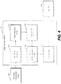
- FIG. 2 is a high-level diagram of the preferred embodiment of the present invention.
- the digital camera 134 FIG. 1 ) is responsible for creating an original digital red-green-blue-panchromatic (RGBP) color filter array (CFA) image 200, also referred to as the digital RGBP CFA image or the RGBP CFA image.
- RGBBP red-green-blue-panchromatic
- CFA color filter array
- cyan-magenta-yellow-panchromatic can be used in place of red-green-blue-panchromatic in the following description.
- the key item is the inclusion of a panchromatic channel. This image is considered to be a sparsely sampled image because each pixel in the image contains only one pixel value of red, green, blue, or panchromatic data.
- a panchromatic image interpolation block 202 produces a reference panchromatic image 204 from the RGBP CFA image 200.
- An edge map generation block 210 produces an edge map 216 from the reference panchromatic image 204.
- an RGB CFA image interpolation block 206 subsequently produces a full-color image 208.
- a full-color image enhancement block 214 produces an enhanced full-color image 212 from the full-color image 208 and the edge map 216.
- the panchromatic image interpolation block 202 and the RGB CFA image interpolation block 206 can be performed in any appropriate ways known to those skilled in the art. Examples can be found in U.S. Patent Publication No. 2007/0024934 . Included in this reference, are examples of using just captured panchromatic pixels to produce the reference panchromatic image, using captured panchromatic pixels and captured color pixels to produce the reference image, using just captured color pixels to produce the full-color image and using captured color pixels and captured panchromatic pixels to produce the full-color image.
- FIG. 3 is a detailed block diagram of the edge map generation block 210 ( FIG. 2 ) for the preferred embodiment.
- a high-pass filtering block 218 produces a high-frequency image 220 from the reference panchromatic image 204 ( FIG. 2 ).
- High-pass filtering is generally performed by one of two methods: direct convolution or as a part of unsharp masking. With direct convolution, the reference panchromatic image 204 ( FIG. 2 ) is convolved with a high-pass kernel and the absolute value of the result is the high-frequency image 220.
- An example of an appropriate high-pass kernel is ⁇ 1 ⁇ 1 ⁇ 1 ⁇ 1 8 ⁇ 1 ⁇ 1 ⁇ 1 ⁇ 1 .
- a thresholding block 222 produced the edge map 216 ( FIG. 2 ) from the high-frequency image 220.
- Thresholding in block 222 is generally performed by testing each pixel value in the high-frequency image 220 against a given threshold value. If the pixel value in the high-frequency image 220 is equal to or greater than the given threshold value, the corresponding pixel value in the edge map is marked as an edge pixel and set to a value that indicates the presence of an edge, e.g., one. If the pixel value in the high-frequency image 220 is less than the given threshold value, the corresponding pixel value in the edge map is marked as a flat pixel and set to a value that indicates the absence of an edge, e.g., zero. Multiple thresholds are used in accordance with the invention.
- a second edge map is produced from the first edge map and the high-frequency image 220 using a smaller second threshold value.
- each pixel location in the first edge map marked as an edge pixel is automatically marked as an edge pixel in the second edge map at the corresponding location.
- the corresponding high-frequency image 220 pixel value is compared to the second threshold value. If the pixel value in the high-frequency image 220 is equal to or greater than the second threshold value, the corresponding pixel value in the second edge map is marked as an edge pixel. If the pixel value in the high-frequency image 220 is less than the second threshold value, the corresponding pixel value in the second edge map is marked as a flat pixel. It will be clear to one skilled in the art that this process can be continued using additional thresholds.
- FIG. 4 is a detailed block diagram of the edge map generation block 210 ( FIG. 2 ) for an alternate embodiment.
- a high-pass filtering block 224 produces a high-frequency image 226 from the reference panchromatic image 204 ( FIG. 2 ).
- the high-frequency image 226 has three channels.
- the first channel contains the edge magnitude value which is the result produced by the same computations as performed by high-pass filtering block 218 ( FIG. 3 ).
- the second channel contains the horizontal gradient value produced by taking the absolute value of a convolution with a horizontal gradient kernel. An example of such a kernel is ⁇ 1 0 1 .
- the third channel contains the vertical gradient value produced by taking the absolute value of a convolution with a vertical gradient kernel. An example of such a kernel is ⁇ 1 0 1 .
- the nonmaximum suppression block 228 produces an edge-thinned high-frequency image 230 from the high-frequency image 226. Comparing the horizontal gradient value to the vertical gradient value for each edge magnitude pixel location generally performs nonmaximum suppression in block 228. If the horizontal gradient value is greater than or equal to the vertical gradient value then the direction of nonmaximum suppression is horizontal. If the vertical gradient value is greater than the horizontal value, the direction of the nonmaximum suppression is vertical.
- FIG. 5 is an example pixel neighborhood of edge magnitude values with the edge magnitude value E 3 being operated on. If the direction of nonmaximum suppression is horizontal, then if E 3 is greater than or equal to both E 2 and E 4 , it is left unaltered. Otherwise, E 3 is set to zero.
- E 3 is set to zero.
- the thresholding block 222 is the same operation as previously described under FIG. 3 .
- edge map 216 ( FIG. 2 ) can be enhanced in any number of ways, e.g., through the use of morphological processing, to reduce the effects of noise or to change the thickness of the features within the edge map 216 ( FIG. 2 ) in accord with its subsequent use.
- the full-color image enhancement block 214 One such full-color image enhancement is noise reduction.
- the central pixel For each pixel in the full-color image 208, subsequently referred to as the central pixel, the corresponding value in the edge map 216 is checked to see if it is marked as either an edge pixel or a flat pixel. If the central pixel is an edge pixel, noise reduction of that pixel value can be skipped in order to preserve the edge detail. If the central pixel is a flat pixel, all of the other flat pixels within a given distance of the central pixel are averaged together to produce a noise-reduced central pixel value.
- a sharpening channel can be produced from the full-color image 208 or from the reference panchromatic image 204 as taught in US Patent Application No. 11/621,139, filed January 9, 2007 .
- the central pixel the corresponding value in the edge map 216 is checked to see if it is marked as either an edge pixel or a flat pixel. If the central pixel is an edge pixel, the full corresponding sharpening channel value is added to the central pixel value to sharpen the edge detail. If the central pixel is a flat pixel, either a part or none of the corresponding sharpening channel value is added to the central pixel value to reduce the unwanted amplification of noise in the full-color image.
- the full corresponding color correction is applied to the full-color image 208 pixel value. If the pixel is a flat pixel, either a partial or no color correction is applied to the full-color image 208 pixel value to reduce the visibility of noise and image processing artifacts.
- FIG. 6 is a high-level diagram an alternate embodiment of the present invention.
- the digital camera 134 as shown in FIG. 1 , is responsible for creating an original digital red-green-blue-panchromatic (RGBP) color filter array (CFA) image 200, also referred to as the digital RGBP CFA image or the RGBP CFA image.
- RGBBP red-green-blue-panchromatic
- CFA color filter array
- other color channel combinations such as cyan-magenta-yellow-panchromatic, can be used in place of red-green-blue-panchromatic in the following description.
- the key item is the inclusion of a panchromatic channel. This image is considered a sparsely sampled image because each pixel in the image contains only one pixel value of red, green, blue, or panchromatic data.
- a panchromatic image interpolation block 202 produces a reference panchromatic image 204 from the RGBP CFA image 200.
- An edge map generation block 210 produces an edge map 216 from the reference panchromatic image 204.
- an RGB CFA image interpolation block 232 subsequently produces a full-color image 234.
- a full-color image enhancement block 214 produces an enhanced full-color image 236 from the full-color image 234 and the edge map 216.
- the panchromatic image interpolation block 202 and the RGB CFA image interpolation block 232 can be performed in any appropriate ways known to those skilled in the art. Examples can be found in U.S. Patent Application No. 2007/0024934 . Included in this reference, are examples of using just captured panchromatic pixels to produce the reference panchromatic image, using captured panchromatic pixels and captured color pixels to produce the reference image, using just captured color pixels to produce the full-color image and using captured color pixels and captured panchromatic pixels to produce the full-color image. The details of the other blocks in FIG. 6 are the same as in the preferred embodiment, shown in the figures.
- edge map-based algorithms disclosed in the preferred embodiments of the present invention can be employed in a variety of user contexts and environments.
- Exemplary contexts and environments include, without limitation, wholesale digital photofinishing (which involves exemplary process steps or stages such as film in, digital processing, prints out), retail digital photofinishing (film in, digital processing, prints out), home printing (home scanned film or digital images, digital processing, prints out), desktop software (software that applies algorithms to digital prints to make them better -or even just to change them), digital fulfillment (digital images in - from media or over the web, digital processing, with images out - in digital form on media, digital form over the web, or printed on hard-copy prints), kiosks (digital or scanned input, digital processing, digital or scanned output), mobile devices (e.g., PDA or cell phone that can be used as a processing unit, a display unit, or a unit to give processing instructions), and as a service offered via the World Wide Web.
- wholesale digital photofinishing which involves exemplary process steps or stages such as film in,
- the edge map-based algorithms can stand alone or can be a component of a larger system solution.
- the interfaces with the algorithm e.g., the scanning or input, the digital processing, the display to a user (if needed), the input of user requests or processing instructions (if needed), the output, can each be on the same or different devices and physical locations, and communication between the devices and locations can be via public or private network connections, or media based communication.
- the algorithms themselves can be fully automatic.
- user input can be used or an operator can review to accept/reject the result. Metadata supplied by a measuring device (e.g. in a camera), can also be used).
- the algorithms can interface with a variety of workflow user interface schemes.
- the edge map-based algorithms disclosed herein in accordance with the invention can have interior components that use various data detection and reduction techniques (e.g., face detection, eye detection, skin detection, flash detection).
- data detection and reduction techniques e.g., face detection, eye detection, skin detection, flash detection.
Description
- The present invention relates to using an edge map to form an enhanced color image from a panchromatic image and a color image.
- Video cameras and digital still cameras generally employ a single image sensor with a color filter array to record a scene. This approach begins with a sparsely populated single-channel image in which the color information is encoded by the color filter array pattern. Subsequent interpolation of the neighboring pixel values permits the reconstruction of a complete three-channel, full-color image. This full-color image, in turn, can be noise-cleaned, sharpened, or color corrected to improve, or enhance, the appearance of the image. This image enhancement can be greatly facilitated by computing an edge map of the image in order to classify the image into edge regions and flat regions. This permits the use of algorithms that perform different computations for edge regions and for flat regions. One popular approach is to either directly detect or synthesize a luminance color channel, e.g. "green", and then to generate an edge map from the luminance image.
U.S. Patent No. 6,614,474 (Malkin et al. ) describes computing a luminance channel and then generating edge information from a set of directional edge detection kernels. The problem with this approach is that edges that vary only in chrominance and not luminance run the risk of being undetected. To address this concern,U.S. Patent No. 5,420,971 (Westerink et al. ) teaches computing a YUV luminance-chrominance image, computing edge information from all three channels (Y, U, and V), and then combining them as an L2-norm to detect both luminance and chrominance edges. The problem with this approach is that the noisiness of the computed luminance-chrominance image is defined by the noisiness of the original color data, e.g., RGB. This level of noise in the original color data is determined, among other things, by the relative narrowness of the spectral frequency response of the individual color channels. When the scene being captured is well lit, e.g., a sunny landscape, the narrowness of the spectral frequency responses is usually not an issue. When the scene is not well lit, e.g., indoors, or the exposure time is necessarily short to reduce motion blur, e.g., at a sporting event, the relative narrowness of the spectral frequency response of the individual color channels can produce noisy images. - Under low-light imaging situations, it is advantageous to have one or more of the pixels in the color filter array unfiltered, i.e. white or panchromatic in spectral sensitivity. These panchromatic pixels have the highest light sensitivity capability of the capture system. Employing panchromatic pixels represents a tradeoff in the capture system between light sensitivity and color spatial resolution. To this end, many four-color color filter array systems have been described.
U.S. Pat. No. 6,529,239 (Dyck et al. ) teaches a green-cyan-yellow-white pattern that is arranged as a 2x2 block that is tessellated over the surface of the sensor.U.S. Pat. No. 6,757,012 (Hubina et al. ) discloses both a red-green-blue-white pattern and a yellow-cyan-magenta-white pattern. In both cases, the colors are arranged in a 2x2 block that is tessellated over the surface of the imager. The difficulty with such systems is that only one-quarter of the pixels in the color filter array have highest light sensitivity, thus limiting the overall low-light performance of the capture device. - To address the need of having more pixels with highest light sensitivity in the color filter array,
U.S. Patent Application Publication No. 2003/0210332 (Frame ) describes a pixel array with most of the pixels being unfiltered. Relatively few pixels are devoted to capturing color information from the scene producing a system with low color spatial resolution capability. Additionally, Frame teaches using simple linear interpolation techniques that are not responsive to or protective of high frequency color spatial details in the image. -
WO97/35438 -
US2007/024934 discloses a method for forming a final digital color image, the method including: capturing an image using an image sensor having panchromatic pixels and color pixels corresponding to at least two color photoresponses; providing from the captured image a digital high resolution panchromatic image and a digital high resolution color differences image; and using the digital high resolution panchromatic image and the digital high resolution color differences image to produce the final digital high resolution full color image.US2006/152596 discloses a method of noise-cleaning an original sparsely populated color digital image, the method including producing a luminance digital image from the original sparsely populated color digital image; producing from the original sparsely populated color digital image at least one sparsely populated chrominance digital image with a resolution lower than the luminance digital image; noise-cleaning the luminance digital image and each digital chrominance image; and producing a noise cleaned sparsely populated color digital image from the noise cleaned luminance and chrominance image(s). - "Noise Reduction Techniques for Bayer-Matrix Images" (Kalevo & Rantanen, Proceedings of the SPIE Vol 4669, 2002) discloses arrangements to apply noise reduction techniques for images captured by a single sensor digital camera.
- "Spectrally Consistent Satellite Image Fusion with Improved Image Priors" (Nielsen et al, Proceedings of the 7th Nordic Signal Processing Symposium, 2006) is an article setting out an improved framework for satellite image fusion.
- "Handbook of Image and Video Processing" (1st ed, 14 June 2000, Edited by Al Bovik) has a Chapter 4.11 by Phillip A Misna and Jeffrey J. Rodriguez entitled "Gradient and Laplacian-Type Edge Detection" (pages 415-431) which describes gradient-based and Laplacian-based edge detection techniques.
- It is an object of the present invention to produce an enhanced digital color image from a digital image having panchromatic and color pixels.
- This object is achieved by a method as set out in claim 1.
- It is a feature of the present invention that images can be captured under low-light conditions with a sensor having panchromatic and color pixels and processing produces an enhanced digital color image produced from the panchromatic and colored pixels.
- The present invention makes use of a color filter array with an appropriate composition of panchromatic and color pixels in order to permit the above method to provide both improved low-light sensitivity and improved color spatial resolution fidelity. The above method preserves and enhances panchromatic and color spatial details and produces an enhanced full-color image.
-
-
FIG. 1 is a perspective of a computer system including a digital camera for implementing the present invention; -
FIG. 2 is a block diagram of a preferred embodiment of the present invention; -
FIG. 3 is a blockdiagram showing block 210 inFIG. 2 in more detail; -
FIG. 4 is a block diagram showing an alternate embodiment ofblock 210 inFIG. 2 in more detail; -
FIG. 5 is a pixel neighborhood used during the execution of the nonmaximum suppression inblock 228 inFIG. 4 ; and -
FIG. 6 is a block diagram of an alternate embodiment of the present invention. - In the following description, a preferred embodiment of the present invention will be described in terms that would ordinarily be implemented as a software program. Those skilled in the art will readily recognize that the equivalent of such software can also be constructed in hardware. Because image manipulation algorithms and systems are well known, the present description will be directed in particular to algorithms and systems forming part of, or cooperating more directly with, the system and method in accordance with the present invention. Other aspects of such algorithms and systems, and hardware or software for producing and otherwise processing the image signals involved therewith, not specifically shown or described herein, can be selected from such systems, algorithms, components and elements known in the art. Given the system as described according to the invention in the following materials, software not specifically shown, suggested or described herein that is useful for implementation of the invention is conventional and within the ordinary skill in such arts.
- Still further, as used herein, the computer program can be stored in a computer readable storage medium, which can include, for example; magnetic storage media such as a magnetic disk (such as a hard drive or a floppy disk) or magnetic tape; optical storage media such as an optical disc, optical tape, or machine readable bar code; solid state electronic storage devices such as random access memory (RAM), or read only memory (ROM); or any other physical device or medium employed to store a computer program.
- Before describing the present invention, it facilitates understanding to note that the present invention is preferably used on any well-known computer system, such as a personal computer. Consequently, the computer system will not be discussed in detail herein. It is also instructive to note that the images are either directly input into the computer system (for example by a digital camera) or digitized before input into the computer system (for example by scanning an original, such as a silver halide film).
- Referring to
FIG. 1 , there is illustrated acomputer system 110 for implementing the present invention. Although thecomputer system 110 is shown for the purpose of illustrating a preferred embodiment, the present invention is not limited to thecomputer system 110 as shown, but can be used on any electronic processing system such as home computers, kiosks, retail or wholesale photofinishing, or any other system for the processing of digital images. Thecomputer system 110 includes a microprocessor-based unit 112 for receiving and processing software programs and for performing other processing functions. A display 114 is electrically connected to the microprocessor-based unit 112 for displaying user-related information associated with the software, e.g., by a graphical user interface. A keyboard 116 is also connected to the microprocessor based unit 112 for permitting a user to input information to the software. As an alternative to using the keyboard 116 for input, a mouse 118 can be used for moving a selector 120 on the display 114 and for selecting an item on which the selector 120 overlays, as is well known in the art. - A compact disk-read only memory (CD-ROM) 124, which typically includes software programs, is inserted into the microprocessor based unit for providing a way of inputting the software programs and other information to the microprocessor based unit 112. In addition, a
floppy disk 126 can also include a software program, and is inserted into the microprocessor-based unit 112 for inputting the software program. The compact disk-read only memory (CD-ROM) 124 or thefloppy disk 126 can alternatively be inserted into externally locateddisk drive unit 122 which is connected to the microprocessor-based unit 112. Still further, the microprocessor-based unit 112 can be programmed, as is well known in the art, for storing the software program internally. The microprocessor-based unit 112 can also have anetwork connection 127, such as a telephone line, to an external network, such as a local area network or the Internet. Aprinter 128 can also be connected to the microprocessor-based unit 112 for printing a hardcopy of the output from thecomputer system 110. - Images can also be displayed on the display 114 via a personal computer card (PC card) 130, such as, as it was formerly known, a PCMCIA card (based on the specifications of the Personal Computer Memory Card International Association), which contains digitized images electronically, embodied in the
PC card 130. ThePC card 130 is ultimately inserted into the microprocessor-based unit 112 for permitting visual display of the image on the display 114. Alternatively, thePC card 130 can be inserted into an externally locatedPC card reader 132 connected to the microprocessor-based unit 112. Images can also be input via thecompact disk 124, thefloppy disk 126, or thenetwork connection 127. Any images stored in thePC card 130, thefloppy disk 126 or thecompact disk 124, or input through thenetwork connection 127, can have been obtained from a variety of sources, such as a digital camera (not shown) or a scanner (not shown). Images can also be input directly from adigital camera 134 via acamera docking port 136 connected to the microprocessor-based unit 112 or directly from thedigital camera 134 via a cable connection 138 to the microprocessor-based unit 112 or via a wireless connection 140 to the microprocessor-based unit 112. - In accordance with the invention, the algorithm can be stored in any of the storage devices heretofore mentioned and applied to images in order to sharpen the images.
-
FIG. 2 is a high-level diagram of the preferred embodiment of the present invention. The digital camera 134 (FIG. 1 ) is responsible for creating an original digital red-green-blue-panchromatic (RGBP) color filter array (CFA)image 200, also referred to as the digital RGBP CFA image or the RGBP CFA image. It is noted at this point that other color channel combinations, such as cyan-magenta-yellow-panchromatic, can be used in place of red-green-blue-panchromatic in the following description. The key item is the inclusion of a panchromatic channel. This image is considered to be a sparsely sampled image because each pixel in the image contains only one pixel value of red, green, blue, or panchromatic data. A panchromaticimage interpolation block 202 produces a referencepanchromatic image 204 from theRGBP CFA image 200. An edgemap generation block 210 produces anedge map 216 from the referencepanchromatic image 204. From theRGBP CFA image 200, an RGB CFAimage interpolation block 206 subsequently produces a full-color image 208. A full-colorimage enhancement block 214 produces an enhanced full-color image 212 from the full-color image 208 and theedge map 216. - In
FIG. 2 , the panchromaticimage interpolation block 202 and the RGB CFAimage interpolation block 206 can be performed in any appropriate ways known to those skilled in the art. Examples can be found inU.S. Patent Publication No. 2007/0024934 . Included in this reference, are examples of using just captured panchromatic pixels to produce the reference panchromatic image, using captured panchromatic pixels and captured color pixels to produce the reference image, using just captured color pixels to produce the full-color image and using captured color pixels and captured panchromatic pixels to produce the full-color image. -
FIG. 3 is a detailed block diagram of the edge map generation block 210 (FIG. 2 ) for the preferred embodiment. A high-pass filtering block 218 produces a high-frequency image 220 from the reference panchromatic image 204 (FIG. 2 ). High-pass filtering is generally performed by one of two methods: direct convolution or as a part of unsharp masking. With direct convolution, the reference panchromatic image 204 (FIG. 2 ) is convolved with a high-pass kernel and the absolute value of the result is the high-frequency image 220. An example of an appropriate high-pass kernel is
FIG. 2 ) is convolved with a low-pass kernel and the resulting low-frequency image is subtracted from the reference panchromatic image 204 (FIG. 2 ). The absolute value of this subtraction is the high-frequency image 220. An example of an appropriate low-pass kernel would be
FIG. 3 , a thresholding block 222 produced the edge map 216 (FIG. 2 ) from the high-frequency image 220. Thresholding in block 222 is generally performed by testing each pixel value in the high-frequency image 220 against a given threshold value. If the pixel value in the high-frequency image 220 is equal to or greater than the given threshold value, the corresponding pixel value in the edge map is marked as an edge pixel and set to a value that indicates the presence of an edge, e.g., one. If the pixel value in the high-frequency image 220 is less than the given threshold value, the corresponding pixel value in the edge map is marked as a flat pixel and set to a value that indicates the absence of an edge, e.g., zero. Multiple thresholds are used in accordance with the invention. In particular, after producing a first edge map using a relatively large first threshold value, a second edge map is produced from the first edge map and the high-frequency image 220 using a smaller second threshold value. In this case, each pixel location in the first edge map marked as an edge pixel, is automatically marked as an edge pixel in the second edge map at the corresponding location. In the case of a pixel location in the first edge map being marked as a flat pixel and at least one of the adjacent pixel locations being marked as an edge pixel, the corresponding high-frequency image 220 pixel value is compared to the second threshold value. If the pixel value in the high-frequency image 220 is equal to or greater than the second threshold value, the corresponding pixel value in the second edge map is marked as an edge pixel. If the pixel value in the high-frequency image 220 is less than the second threshold value, the corresponding pixel value in the second edge map is marked as a flat pixel. It will be clear to one skilled in the art that this process can be continued using additional thresholds. -
FIG. 4 is a detailed block diagram of the edge map generation block 210 (FIG. 2 ) for an alternate embodiment. A high-pass filtering block 224 produces a high-frequency image 226 from the reference panchromatic image 204 (FIG. 2 ). The high-frequency image 226 has three channels. The first channel contains the edge magnitude value which is the result produced by the same computations as performed by high-pass filtering block 218 (FIG. 3 ). The second channel contains the horizontal gradient value produced by taking the absolute value of a convolution with a horizontal gradient kernel. An example of such a kernel is

nonmaximum suppression block 228 produces an edge-thinned high-frequency image 230 from the high-frequency image 226. Comparing the horizontal gradient value to the vertical gradient value for each edge magnitude pixel location generally performs nonmaximum suppression inblock 228. If the horizontal gradient value is greater than or equal to the vertical gradient value then the direction of nonmaximum suppression is horizontal. If the vertical gradient value is greater than the horizontal value, the direction of the nonmaximum suppression is vertical.FIG. 5 is an example pixel neighborhood of edge magnitude values with the edge magnitude value E3 being operated on. If the direction of nonmaximum suppression is horizontal, then if E3 is greater than or equal to both E2 and E4, it is left unaltered. Otherwise, E3 is set to zero. If the direction of nonmaximum suppression is vertical, then if E3 is greater than or equal to both E1 and E5, it is left unaltered. Otherwise, E3 is set to zero. InFIG. 4 , the thresholding block 222 is the same operation as previously described underFIG. 3 . - It will be evident to one skilled in the art that the edge map 216 (
FIG. 2 ) can be enhanced in any number of ways, e.g., through the use of morphological processing, to reduce the effects of noise or to change the thickness of the features within the edge map 216 (FIG. 2 ) in accord with its subsequent use. - Returning to
FIG. 2 , several examples are now given for the full-colorimage enhancement block 214. One such full-color image enhancement is noise reduction. For each pixel in the full-color image 208, subsequently referred to as the central pixel, the corresponding value in theedge map 216 is checked to see if it is marked as either an edge pixel or a flat pixel. If the central pixel is an edge pixel, noise reduction of that pixel value can be skipped in order to preserve the edge detail. If the central pixel is a flat pixel, all of the other flat pixels within a given distance of the central pixel are averaged together to produce a noise-reduced central pixel value. - Another example of full-color image enhancement is sharpening (edge enhancement.) A sharpening channel can be produced from the full-
color image 208 or from the referencepanchromatic image 204 as taught inUS Patent Application No. 11/621,139, filed January 9, 2007 color image 208, subsequently referred to as the central pixel, the corresponding value in theedge map 216 is checked to see if it is marked as either an edge pixel or a flat pixel. If the central pixel is an edge pixel, the full corresponding sharpening channel value is added to the central pixel value to sharpen the edge detail. If the central pixel is a flat pixel, either a part or none of the corresponding sharpening channel value is added to the central pixel value to reduce the unwanted amplification of noise in the full-color image. - Another example of full-color image enhancement is color correction. Color correction is usually performed by multiplying the color channels value of the full-
color image 208 by a 3x3 matrix into order to produce the enhanced full-color image 212. This computation takes the following form:
color image 208 color channels values and (R',G',B') refer to the enhanced full-color image 212. For each pixel in the full-color image 208 the corresponding value in theedge map 216 is checked to see if it is marked as either an edge pixel or a flat pixel. If the pixel is an edge pixel, the full corresponding color correction is applied to the full-color image 208 pixel value. If the pixel is a flat pixel, either a partial or no color correction is applied to the full-color image 208 pixel value to reduce the visibility of noise and image processing artifacts. -
FIG. 6 is a high-level diagram an alternate embodiment of the present invention. Thedigital camera 134, as shown inFIG. 1 , is responsible for creating an original digital red-green-blue-panchromatic (RGBP) color filter array (CFA)image 200, also referred to as the digital RGBP CFA image or the RGBP CFA image. It is noted at this point, other color channel combinations, such as cyan-magenta-yellow-panchromatic, can be used in place of red-green-blue-panchromatic in the following description. The key item is the inclusion of a panchromatic channel. This image is considered a sparsely sampled image because each pixel in the image contains only one pixel value of red, green, blue, or panchromatic data. A panchromaticimage interpolation block 202 produces a referencepanchromatic image 204 from theRGBP CFA image 200. An edgemap generation block 210 produces anedge map 216 from the referencepanchromatic image 204. From theRGBP CFA image 200 and the referencepanchromatic image 204, an RGB CFA image interpolation block 232 subsequently produces a full-color image 234. A full-colorimage enhancement block 214 produces an enhanced full-color image 236 from the full-color image 234 and theedge map 216. - In
FIG. 6 , the panchromaticimage interpolation block 202 and the RGB CFA image interpolation block 232 can be performed in any appropriate ways known to those skilled in the art. Examples can be found inU.S. Patent Application No. 2007/0024934 . Included in this reference, are examples of using just captured panchromatic pixels to produce the reference panchromatic image, using captured panchromatic pixels and captured color pixels to produce the reference image, using just captured color pixels to produce the full-color image and using captured color pixels and captured panchromatic pixels to produce the full-color image. The details of the other blocks inFIG. 6 are the same as in the preferred embodiment, shown in the figures. - The edge map-based algorithms disclosed in the preferred embodiments of the present invention can be employed in a variety of user contexts and environments. Exemplary contexts and environments include, without limitation, wholesale digital photofinishing (which involves exemplary process steps or stages such as film in, digital processing, prints out), retail digital photofinishing (film in, digital processing, prints out), home printing (home scanned film or digital images, digital processing, prints out), desktop software (software that applies algorithms to digital prints to make them better -or even just to change them), digital fulfillment (digital images in - from media or over the web, digital processing, with images out - in digital form on media, digital form over the web, or printed on hard-copy prints), kiosks (digital or scanned input, digital processing, digital or scanned output), mobile devices (e.g., PDA or cell phone that can be used as a processing unit, a display unit, or a unit to give processing instructions), and as a service offered via the World Wide Web.
- In each case, the edge map-based algorithms can stand alone or can be a component of a larger system solution. Furthermore, the interfaces with the algorithm, e.g., the scanning or input, the digital processing, the display to a user (if needed), the input of user requests or processing instructions (if needed), the output, can each be on the same or different devices and physical locations, and communication between the devices and locations can be via public or private network connections, or media based communication. Consistent with the foregoing disclosure of the present invention, the algorithms themselves can be fully automatic. However, user input can be used or an operator can review to accept/reject the result. Metadata supplied by a measuring device (e.g. in a camera), can also be used). Moreover, the algorithms can interface with a variety of workflow user interface schemes.
- The edge map-based algorithms disclosed herein in accordance with the invention can have interior components that use various data detection and reduction techniques (e.g., face detection, eye detection, skin detection, flash detection).
-
- 110
- Computer System
- 112
- Microprocessor-based Unit
- 114
- Display
- 116
- Keyboard
- 118
- Mouse
- 120
- Selector on Display
- 122
- Disk Drive Unit
- 124
- Compact Disk - read Only Memory (CD-ROM)
- 126
- Floppy Disk
- 127
- Network Connection
- 128
- Printer
- 130
- Personal Computer Card (PC card)
- 132
- PC Card Reader
- 134
- Digital Camera
- 136
- Camera Docking Port
- 138
- Cable Connection
- 140
- Wireless Connection
- 200
- RGBP CFA Image
- 202
- Panchromatic Image Interpolation
- 204
- Reference Panchromatic Image
- 206
- RGB CFA Image Interpolation
- 208
- Full-Color Image
- 210
- Edge Map Generation
- 212
- Enhanced Full-Color Image
- 214
- Full-Color Image Enhancement
- 216
- Edge Map
- 218
- High-Pass Filtering
- 220
- High-Frequency Image
- 222
- Thresholding
- 224
- High-Pass Filtering
- 226
- High-Frequency Image
- 228
- Nonmaximum Suppression
- 230
- Edge-Thinned High-Frequency Image
- 232
- RGB CFA Image Interpolation
- 234
- Full-Color Image
- 236
- Enhanced Full-Color Image
Claims (6)
- A computer-implemented method of providing an enhanced full-color image (212, 236) of a scene, comprising:a. using a captured image (200) of the scene that was captured by a two-dimensional sensor array having both color and panchromatic pixels;b. forming a full-color image (208, 234) in response to the captured color pixels;c. forming a reference panchromatic image (204) in response to the captured panchromatic pixels; characterized byd. forming an edge map (216) in response to the reference panchromatic image; wherein forming the edge map comprises:d(1). forming a high-frequency image (220) of the reference panchromatic image (204);d(2). forming a first edge map by comparing each pixel value in the high-frequency image (220) of the reference panchromatic image against a predetermined first threshold value, wherein if the pixel value is equal to or greater than the first threshold value, then the pixel value in the first edge map is marked as an edge pixel and set to a value that indicates the presence of an edge, if the pixel value is less than the predetermined threshold value, then the pixel value in the first edge map is marked as a flat pixel and set to a value that indicates the absence of an edge;d(3). forming a second edge map (216) from the first edge map and the high frequency image (220) using a second threshold value that is smaller than the first threshold value, wherein each pixel location marked as an edge pixel in the first edge map is marked as an edge pixel at a corresponding location in the second edge map (216) and, for each pixel location in the first edge map that was marked as a flat pixel and has at least one adjacent pixel location marked as an edge pixel, the pixel value in the high-frequency image (220) corresponding to that pixel location is compared to the second threshold value, wherein if the pixel value in the high-frequency image (220) is equal to or greater than the second threshold value, then the pixel value in the second edge map (216) is marked as an edge pixel and set to a value that indicates the presence of an edge, and wherein if the pixel value in the high-frequency image is less than the predetermined second threshold value, then the pixel value in the edge map is marked as a flat pixel and set to a value that indicates the absence of an edge; ande. using the second edge map (216) to enhance the full-color image (208, 234).
- The method according to claim 1 wherein step b includes using both the captured color pixels and the captured panchromatic pixels to form the full color image (208, 234).
- The method according to claim 2 further using the reference panchromatic image (204) to form the full color image (208, 234).
- The method according to claim 1 wherein the second edge map (216) is used to provide noise cleaning.
- The method according to claim 1 wherein the second edge map (216) is used to provide sharpening.
- The method according to claim 1 wherein the second edge map (216) is used to provide color correction.
Applications Claiming Priority (2)
| Application Number | Priority Date | Filing Date | Title |
|---|---|---|---|
| US11/694,034 US7844127B2 (en) | 2007-03-30 | 2007-03-30 | Edge mapping using panchromatic pixels |
| PCT/US2008/003941 WO2008121280A2 (en) | 2007-03-30 | 2008-03-26 | Edge mapping using panchromatic pixels |
Publications (2)
| Publication Number | Publication Date |
|---|---|
| EP2130176A2 EP2130176A2 (en) | 2009-12-09 |
| EP2130176B1 true EP2130176B1 (en) | 2017-06-07 |
Family
ID=39794492
Family Applications (1)
| Application Number | Title | Priority Date | Filing Date |
|---|---|---|---|
| EP08742275.4A Active EP2130176B1 (en) | 2007-03-30 | 2008-03-26 | Edge mapping using panchromatic pixels |
Country Status (6)
| Country | Link |
|---|---|
| US (1) | US7844127B2 (en) |
| EP (1) | EP2130176B1 (en) |
| JP (1) | JP5395053B2 (en) |
| CN (1) | CN101652798B (en) |
| TW (1) | TWI467495B (en) |
| WO (1) | WO2008121280A2 (en) |
Families Citing this family (27)
| Publication number | Priority date | Publication date | Assignee | Title |
|---|---|---|---|---|
| US7844127B2 (en) * | 2007-03-30 | 2010-11-30 | Eastman Kodak Company | Edge mapping using panchromatic pixels |
| US8594451B2 (en) * | 2007-03-30 | 2013-11-26 | Omnivision Technologies, Inc. | Edge mapping incorporating panchromatic pixels |
| US8837849B2 (en) * | 2007-06-26 | 2014-09-16 | Google Inc. | Method for noise-robust color changes in digital images |
| WO2009128783A1 (en) * | 2008-04-14 | 2009-10-22 | Xid Technologies Pte Ltd | An image synthesis method |
| JP5259449B2 (en) * | 2009-02-17 | 2013-08-07 | オリンパス株式会社 | Image processing apparatus and method, and program |
| US8724928B2 (en) * | 2009-08-31 | 2014-05-13 | Intellectual Ventures Fund 83 Llc | Using captured high and low resolution images |
| DE102010041569B4 (en) * | 2010-09-28 | 2017-04-06 | Leica Geosystems Ag | Digital camera system, color filter element for digital camera system, method for determining deviations between the cameras of a digital camera system and image processing unit for digital camera system |
| CN102034225B (en) * | 2010-12-20 | 2012-05-23 | 天津大学 | Edge mode-based image color component interpolating method |
| DE202012013411U1 (en) | 2011-04-25 | 2016-11-15 | Terra Bella Technologies Inc. | Systems for overhead image and video display |
| US9237257B1 (en) * | 2013-06-14 | 2016-01-12 | Xilinx, Inc. | Circuits for and methods of generating a digital image |
| WO2015192056A1 (en) | 2014-06-13 | 2015-12-17 | Urthecast Corp. | Systems and methods for processing and providing terrestrial and/or space-based earth observation video |
| US9697434B2 (en) * | 2014-12-10 | 2017-07-04 | Omnivision Technologies, Inc. | Edge detection system and methods |
| US10871561B2 (en) | 2015-03-25 | 2020-12-22 | Urthecast Corp. | Apparatus and methods for synthetic aperture radar with digital beamforming |
| CA2990063A1 (en) | 2015-06-16 | 2017-03-16 | King Abdulaziz City Of Science And Technology | Efficient planar phased array antenna assembly |
| US10955546B2 (en) | 2015-11-25 | 2021-03-23 | Urthecast Corp. | Synthetic aperture radar imaging apparatus and methods |
| US11378682B2 (en) | 2017-05-23 | 2022-07-05 | Spacealpha Insights Corp. | Synthetic aperture radar imaging apparatus and methods for moving targets |
| CA3064735C (en) | 2017-05-23 | 2022-06-21 | Urthecast Corp. | Synthetic aperture radar imaging apparatus and methods |
| CA3083033A1 (en) | 2017-11-22 | 2019-11-28 | Urthecast Corp. | Synthetic aperture radar apparatus and methods |
| US10552708B2 (en) | 2018-03-07 | 2020-02-04 | Xerox Corporation | Method and system for extracting impression marks using a mobile application |
| CN114422766A (en) * | 2018-08-03 | 2022-04-29 | 杭州海康威视数字技术股份有限公司 | Image acquisition equipment |
| US11164039B2 (en) | 2019-10-23 | 2021-11-02 | International Business Machines Corporation | Framework for few-shot temporal action localization |
| CN111586375B (en) * | 2020-05-08 | 2021-06-11 | Oppo广东移动通信有限公司 | High dynamic range image processing system and method, electronic device, and readable storage medium |
| CN111711766B (en) * | 2020-06-17 | 2022-01-04 | Oppo广东移动通信有限公司 | Image processing method and device, terminal and computer readable storage medium |
| CN111711755B (en) * | 2020-06-28 | 2022-01-04 | Oppo广东移动通信有限公司 | Image processing method and device, terminal and computer readable storage medium |
| CN113766231A (en) * | 2020-07-08 | 2021-12-07 | Oppo广东移动通信有限公司 | Image acquisition method, camera assembly and mobile terminal |
| CN114466170B (en) * | 2021-08-27 | 2023-10-31 | 锐芯微电子股份有限公司 | Image processing method and system |
| US20230196621A1 (en) * | 2021-12-17 | 2023-06-22 | Meta Platforms Technologies, Llc | Sparse rgb filter hardware accelerator |
Family Cites Families (42)
| Publication number | Priority date | Publication date | Assignee | Title |
|---|---|---|---|---|
| US4618990A (en) * | 1984-11-15 | 1986-10-21 | General Electric Company | Edge enhancement filtering for digital fluorography images |
| DE69312257T2 (en) * | 1993-02-11 | 1998-01-29 | Agfa Gevaert Nv | Radiation field detection method |
| US5420971A (en) * | 1994-01-07 | 1995-05-30 | Panasonic Technologies, Inc. | Image edge finder which operates over multiple picture element ranges |
| GB9605527D0 (en) * | 1996-03-15 | 1996-05-15 | Vlsi Vision Ltd | Image restoration |
| US6529239B1 (en) * | 1998-06-01 | 2003-03-04 | Fairchild Imaging, Inc. | Image sensor with stripes of cyan filter material perpendicular to stripes of yellow filter material |
| US6614474B1 (en) * | 1998-08-27 | 2003-09-02 | Polycom, Inc. | Electronic pan tilt zoom video camera with adaptive edge sharpening filter |
| US6621937B1 (en) * | 1999-10-08 | 2003-09-16 | Eastman Kodak Company | Removing chroma noise from digital images by using variable shape pixel neighborhood regions |
| US6757012B1 (en) * | 2000-01-13 | 2004-06-29 | Biomorphic Vlsi, Inc. | Color selection for sparse color image reconstruction |
| US6801672B1 (en) * | 2001-06-01 | 2004-10-05 | Bruce A. Thomas | Removing noise from a color image using wavelets |
| US7003173B2 (en) * | 2001-06-12 | 2006-02-21 | Sharp Laboratories Of America, Inc. | Filter for combined de-ringing and edge sharpening |
| KR100403601B1 (en) * | 2001-12-21 | 2003-10-30 | 삼성전자주식회사 | Apparatus and method for enhancing edge of image |
| JP3988457B2 (en) * | 2001-12-25 | 2007-10-10 | ソニー株式会社 | Imaging apparatus and signal processing method for solid-state imaging device |
| JP2003263643A (en) * | 2002-03-07 | 2003-09-19 | Univ Osaka | Device and method for judging photographing direction |
| US7012643B2 (en) * | 2002-05-08 | 2006-03-14 | Ball Aerospace & Technologies Corp. | One chip, low light level color camera |
| US7099518B2 (en) * | 2002-07-18 | 2006-08-29 | Tektronix, Inc. | Measurement of blurring in video sequences |
| JP2004304706A (en) * | 2003-04-01 | 2004-10-28 | Fuji Photo Film Co Ltd | Solid-state imaging apparatus and interpolation processing method thereof |
| US7305103B2 (en) * | 2003-06-30 | 2007-12-04 | The Boeing Company | System and method for generating pan sharpened multispectral imagery |
| KR100548611B1 (en) * | 2003-08-07 | 2006-01-31 | 삼성전기주식회사 | Apparatus and method for edge emphasis in image processing |
| US7298922B1 (en) * | 2004-07-07 | 2007-11-20 | Lockheed Martin Corporation | Synthetic panchromatic imagery method and system |
| TWI255134B (en) * | 2004-10-29 | 2006-05-11 | Sunplus Technology Co Ltd | System to suppress color noise |
| JP4781670B2 (en) * | 2004-12-17 | 2011-09-28 | 三星電子株式会社 | Imaging device |
| US20060152596A1 (en) * | 2005-01-11 | 2006-07-13 | Eastman Kodak Company | Noise cleaning sparsely populated color digital images |
| JP4702088B2 (en) * | 2005-03-31 | 2011-06-15 | カシオ計算機株式会社 | Image signal noise reduction method, noise reduction apparatus, and imaging apparatus |
| US7577311B2 (en) * | 2005-05-03 | 2009-08-18 | Eastman Kodak Company | Color fringe desaturation for electronic imagers |
| US8139130B2 (en) * | 2005-07-28 | 2012-03-20 | Omnivision Technologies, Inc. | Image sensor with improved light sensitivity |
| US7830430B2 (en) * | 2005-07-28 | 2010-11-09 | Eastman Kodak Company | Interpolation of panchromatic and color pixels |
| US8274715B2 (en) * | 2005-07-28 | 2012-09-25 | Omnivision Technologies, Inc. | Processing color and panchromatic pixels |
| JP2007043285A (en) * | 2005-08-01 | 2007-02-15 | Olympus Corp | Shake vector detecting apparatus, camera system, shake vector detection method, and shake vector detection program |
| JP4325599B2 (en) * | 2005-08-25 | 2009-09-02 | ソニー株式会社 | Imaging apparatus and display control method |
| US7688368B2 (en) * | 2006-01-27 | 2010-03-30 | Eastman Kodak Company | Image sensor with improved light sensitivity |
| US7916362B2 (en) * | 2006-05-22 | 2011-03-29 | Eastman Kodak Company | Image sensor with improved light sensitivity |
| US7876956B2 (en) * | 2006-11-10 | 2011-01-25 | Eastman Kodak Company | Noise reduction of panchromatic and color image |
| US20080123997A1 (en) * | 2006-11-29 | 2008-05-29 | Adams James E | Providing a desired resolution color image |
| US7769229B2 (en) * | 2006-11-30 | 2010-08-03 | Eastman Kodak Company | Processing images having color and panchromatic pixels |
| US7769230B2 (en) * | 2006-11-30 | 2010-08-03 | Eastman Kodak Company | Producing low resolution images |
| US7893976B2 (en) * | 2006-12-01 | 2011-02-22 | Eastman Kodak Company | Light sensitivity in image sensors |
| US7769241B2 (en) * | 2007-01-09 | 2010-08-03 | Eastman Kodak Company | Method of sharpening using panchromatic pixels |
| US8594451B2 (en) * | 2007-03-30 | 2013-11-26 | Omnivision Technologies, Inc. | Edge mapping incorporating panchromatic pixels |
| US7844127B2 (en) * | 2007-03-30 | 2010-11-30 | Eastman Kodak Company | Edge mapping using panchromatic pixels |
| US7889921B2 (en) * | 2007-05-23 | 2011-02-15 | Eastman Kodak Company | Noise reduced color image using panchromatic image |
| US20090051984A1 (en) * | 2007-08-23 | 2009-02-26 | O'brien Michele | Image sensor having checkerboard pattern |
| US8164651B2 (en) * | 2008-04-29 | 2012-04-24 | Omnivision Technologies, Inc. | Concentric exposure sequence for image sensor |
-
2007
- 2007-03-30 US US11/694,034 patent/US7844127B2/en active Active
-
2008
- 2008-03-26 CN CN200880011120.4A patent/CN101652798B/en active Active
- 2008-03-26 JP JP2010502092A patent/JP5395053B2/en active Active
- 2008-03-26 EP EP08742275.4A patent/EP2130176B1/en active Active
- 2008-03-26 WO PCT/US2008/003941 patent/WO2008121280A2/en active Application Filing
- 2008-03-28 TW TW97111571A patent/TWI467495B/en active
Non-Patent Citations (2)
| Title |
|---|
| KALEVO O ET AL: "NOISE REDUCTION TECHNIQUES FOR BAYER-MATRIX IMAGES", PROCEEDINGS OF SPIE, S P I E - INTERNATIONAL SOCIETY FOR OPTICAL ENGINEERING, US, vol. 4669, 21 January 2002 (2002-01-21), pages 348 - 359, XP009004110, ISSN: 0277-786X, ISBN: 978-1-62841-684-8, DOI: 10.1117/12.463440 * |
| PHILLIP A MLSNA ET AL: "Handbook of Image and Video Processing, Gradient and Laplacian-Type Edge Detection", 14 June 2000, HANDBOOK OF IMAGE AND VIDEO PROCESSING; [ACADEMIC PRESS SERIES IN COMMUNICATIONS, NETWORKING AND MULTIMEDIA], ACADEMIC PRESS, SAN DIEGO [U.A.], PAGE(S) 415 - 431, ISBN: 978-0-12-119790-2, XP002657063 * |
Also Published As
| Publication number | Publication date |
|---|---|
| JP2010525427A (en) | 2010-07-22 |
| EP2130176A2 (en) | 2009-12-09 |
| WO2008121280A2 (en) | 2008-10-09 |
| CN101652798A (en) | 2010-02-17 |
| US7844127B2 (en) | 2010-11-30 |
| WO2008121280A3 (en) | 2009-05-28 |
| TW200903347A (en) | 2009-01-16 |
| US20080240601A1 (en) | 2008-10-02 |
| TWI467495B (en) | 2015-01-01 |
| JP5395053B2 (en) | 2014-01-22 |
| CN101652798B (en) | 2017-05-17 |
Similar Documents
| Publication | Publication Date | Title |
|---|---|---|
| EP2130176B1 (en) | Edge mapping using panchromatic pixels | |
| EP2130175B1 (en) | Edge mapping incorporating panchromatic pixels | |
| US8224085B2 (en) | Noise reduced color image using panchromatic image | |
| EP2089848B1 (en) | Noise reduction of panchromatic and color image | |
| EP2102815B1 (en) | Method of sharpening using panchromatic pixels | |
| EP1977613B1 (en) | Interpolation of panchromatic and color pixels | |
| US20080123997A1 (en) | Providing a desired resolution color image | |
| US20060152596A1 (en) | Noise cleaning sparsely populated color digital images | |
| EP1371015A2 (en) | Bilateral filtering in a demosaicing process | |
| US6804392B1 (en) | Removing color aliasing artifacts from color digital images |
Legal Events
| Date | Code | Title | Description |
|---|---|---|---|
| PUAI | Public reference made under article 153(3) epc to a published international application that has entered the european phase |
Free format text: ORIGINAL CODE: 0009012 |
|
| 17P | Request for examination filed |
Effective date: 20090915 |
|
| AK | Designated contracting states |
Kind code of ref document: A2 Designated state(s): AT BE BG CH CY CZ DE DK EE ES FI FR GB GR HR HU IE IS IT LI LT LU LV MC MT NL NO PL PT RO SE SI SK TR |
|
| 17Q | First examination report despatched |
Effective date: 20100201 |
|
| RAP1 | Party data changed (applicant data changed or rights of an application transferred) |
Owner name: OMNIVISION TECHNOLOGIES, INC. |
|
| DAX | Request for extension of the european patent (deleted) | ||
| GRAP | Despatch of communication of intention to grant a patent |
Free format text: ORIGINAL CODE: EPIDOSNIGR1 |
|
| STAA | Information on the status of an ep patent application or granted ep patent |
Free format text: STATUS: GRANT OF PATENT IS INTENDED |
|
| INTG | Intention to grant announced |
Effective date: 20161223 |
|
| GRAS | Grant fee paid |
Free format text: ORIGINAL CODE: EPIDOSNIGR3 |
|
| GRAA | (expected) grant |
Free format text: ORIGINAL CODE: 0009210 |
|
| STAA | Information on the status of an ep patent application or granted ep patent |
Free format text: STATUS: THE PATENT HAS BEEN GRANTED |
|
| AK | Designated contracting states |
Kind code of ref document: B1 Designated state(s): AT BE BG CH CY CZ DE DK EE ES FI FR GB GR HR HU IE IS IT LI LT LU LV MC MT NL NO PL PT RO SE SI SK TR |
|
| REG | Reference to a national code |
Ref country code: GB Ref legal event code: FG4D |
|
| GRAA | (expected) grant |
Free format text: ORIGINAL CODE: 0009210 |
|
| REG | Reference to a national code |
Ref country code: CH Ref legal event code: EP Ref country code: AT Ref legal event code: REF Ref document number: 899727 Country of ref document: AT Kind code of ref document: T Effective date: 20170615 |
|
| REG | Reference to a national code |
Ref country code: IE Ref legal event code: FG4D |
|
| REG | Reference to a national code |
Ref country code: DE Ref legal event code: R096 Ref document number: 602008050580 Country of ref document: DE |
|
| REG | Reference to a national code |
Ref country code: NL Ref legal event code: MP Effective date: 20170607 |
|
| REG | Reference to a national code |
Ref country code: LT Ref legal event code: MG4D |
|
| PG25 | Lapsed in a contracting state [announced via postgrant information from national office to epo] |
Ref country code: GR Free format text: LAPSE BECAUSE OF FAILURE TO SUBMIT A TRANSLATION OF THE DESCRIPTION OR TO PAY THE FEE WITHIN THE PRESCRIBED TIME-LIMIT Effective date: 20170908 Ref country code: LT Free format text: LAPSE BECAUSE OF FAILURE TO SUBMIT A TRANSLATION OF THE DESCRIPTION OR TO PAY THE FEE WITHIN THE PRESCRIBED TIME-LIMIT Effective date: 20170607 Ref country code: NO Free format text: LAPSE BECAUSE OF FAILURE TO SUBMIT A TRANSLATION OF THE DESCRIPTION OR TO PAY THE FEE WITHIN THE PRESCRIBED TIME-LIMIT Effective date: 20170907 Ref country code: ES Free format text: LAPSE BECAUSE OF FAILURE TO SUBMIT A TRANSLATION OF THE DESCRIPTION OR TO PAY THE FEE WITHIN THE PRESCRIBED TIME-LIMIT Effective date: 20170607 Ref country code: HR Free format text: LAPSE BECAUSE OF FAILURE TO SUBMIT A TRANSLATION OF THE DESCRIPTION OR TO PAY THE FEE WITHIN THE PRESCRIBED TIME-LIMIT Effective date: 20170607 Ref country code: FI Free format text: LAPSE BECAUSE OF FAILURE TO SUBMIT A TRANSLATION OF THE DESCRIPTION OR TO PAY THE FEE WITHIN THE PRESCRIBED TIME-LIMIT Effective date: 20170607 |
|
| REG | Reference to a national code |
Ref country code: AT Ref legal event code: MK05 Ref document number: 899727 Country of ref document: AT Kind code of ref document: T Effective date: 20170607 |
|
| PG25 | Lapsed in a contracting state [announced via postgrant information from national office to epo] |
Ref country code: SE Free format text: LAPSE BECAUSE OF FAILURE TO SUBMIT A TRANSLATION OF THE DESCRIPTION OR TO PAY THE FEE WITHIN THE PRESCRIBED TIME-LIMIT Effective date: 20170607 Ref country code: NL Free format text: LAPSE BECAUSE OF FAILURE TO SUBMIT A TRANSLATION OF THE DESCRIPTION OR TO PAY THE FEE WITHIN THE PRESCRIBED TIME-LIMIT Effective date: 20170607 Ref country code: LV Free format text: LAPSE BECAUSE OF FAILURE TO SUBMIT A TRANSLATION OF THE DESCRIPTION OR TO PAY THE FEE WITHIN THE PRESCRIBED TIME-LIMIT Effective date: 20170607 Ref country code: BG Free format text: LAPSE BECAUSE OF FAILURE TO SUBMIT A TRANSLATION OF THE DESCRIPTION OR TO PAY THE FEE WITHIN THE PRESCRIBED TIME-LIMIT Effective date: 20170907 |
|
| PG25 | Lapsed in a contracting state [announced via postgrant information from national office to epo] |
Ref country code: RO Free format text: LAPSE BECAUSE OF FAILURE TO SUBMIT A TRANSLATION OF THE DESCRIPTION OR TO PAY THE FEE WITHIN THE PRESCRIBED TIME-LIMIT Effective date: 20170607 Ref country code: SK Free format text: LAPSE BECAUSE OF FAILURE TO SUBMIT A TRANSLATION OF THE DESCRIPTION OR TO PAY THE FEE WITHIN THE PRESCRIBED TIME-LIMIT Effective date: 20170607 Ref country code: EE Free format text: LAPSE BECAUSE OF FAILURE TO SUBMIT A TRANSLATION OF THE DESCRIPTION OR TO PAY THE FEE WITHIN THE PRESCRIBED TIME-LIMIT Effective date: 20170607 Ref country code: CZ Free format text: LAPSE BECAUSE OF FAILURE TO SUBMIT A TRANSLATION OF THE DESCRIPTION OR TO PAY THE FEE WITHIN THE PRESCRIBED TIME-LIMIT Effective date: 20170607 Ref country code: AT Free format text: LAPSE BECAUSE OF FAILURE TO SUBMIT A TRANSLATION OF THE DESCRIPTION OR TO PAY THE FEE WITHIN THE PRESCRIBED TIME-LIMIT Effective date: 20170607 |
|
| REG | Reference to a national code |
Ref country code: FR Ref legal event code: PLFP Year of fee payment: 11 |
|
| PG25 | Lapsed in a contracting state [announced via postgrant information from national office to epo] |
Ref country code: IT Free format text: LAPSE BECAUSE OF FAILURE TO SUBMIT A TRANSLATION OF THE DESCRIPTION OR TO PAY THE FEE WITHIN THE PRESCRIBED TIME-LIMIT Effective date: 20170607 Ref country code: IS Free format text: LAPSE BECAUSE OF FAILURE TO SUBMIT A TRANSLATION OF THE DESCRIPTION OR TO PAY THE FEE WITHIN THE PRESCRIBED TIME-LIMIT Effective date: 20171007 Ref country code: PL Free format text: LAPSE BECAUSE OF FAILURE TO SUBMIT A TRANSLATION OF THE DESCRIPTION OR TO PAY THE FEE WITHIN THE PRESCRIBED TIME-LIMIT Effective date: 20170607 |
|
| REG | Reference to a national code |
Ref country code: DE Ref legal event code: R097 Ref document number: 602008050580 Country of ref document: DE |
|
| PLBE | No opposition filed within time limit |
Free format text: ORIGINAL CODE: 0009261 |
|
| STAA | Information on the status of an ep patent application or granted ep patent |
Free format text: STATUS: NO OPPOSITION FILED WITHIN TIME LIMIT |
|
| PG25 | Lapsed in a contracting state [announced via postgrant information from national office to epo] |
Ref country code: DK Free format text: LAPSE BECAUSE OF FAILURE TO SUBMIT A TRANSLATION OF THE DESCRIPTION OR TO PAY THE FEE WITHIN THE PRESCRIBED TIME-LIMIT Effective date: 20170607 |
|
| 26N | No opposition filed |
Effective date: 20180308 |
|
| PG25 | Lapsed in a contracting state [announced via postgrant information from national office to epo] |
Ref country code: SI Free format text: LAPSE BECAUSE OF FAILURE TO SUBMIT A TRANSLATION OF THE DESCRIPTION OR TO PAY THE FEE WITHIN THE PRESCRIBED TIME-LIMIT Effective date: 20170607 |
|
| PG25 | Lapsed in a contracting state [announced via postgrant information from national office to epo] |
Ref country code: MC Free format text: LAPSE BECAUSE OF FAILURE TO SUBMIT A TRANSLATION OF THE DESCRIPTION OR TO PAY THE FEE WITHIN THE PRESCRIBED TIME-LIMIT Effective date: 20170607 |
|
| REG | Reference to a national code |
Ref country code: BE Ref legal event code: MM Effective date: 20180331 |
|
| REG | Reference to a national code |
Ref country code: IE Ref legal event code: MM4A |
|
| PG25 | Lapsed in a contracting state [announced via postgrant information from national office to epo] |
Ref country code: LU Free format text: LAPSE BECAUSE OF NON-PAYMENT OF DUE FEES Effective date: 20180326 |
|
| PG25 | Lapsed in a contracting state [announced via postgrant information from national office to epo] |
Ref country code: IE Free format text: LAPSE BECAUSE OF NON-PAYMENT OF DUE FEES Effective date: 20180326 |
|
| PG25 | Lapsed in a contracting state [announced via postgrant information from national office to epo] |
Ref country code: BE Free format text: LAPSE BECAUSE OF NON-PAYMENT OF DUE FEES Effective date: 20180331 |
|
| PG25 | Lapsed in a contracting state [announced via postgrant information from national office to epo] |
Ref country code: MT Free format text: LAPSE BECAUSE OF NON-PAYMENT OF DUE FEES Effective date: 20180326 |
|
| PG25 | Lapsed in a contracting state [announced via postgrant information from national office to epo] |
Ref country code: TR Free format text: LAPSE BECAUSE OF FAILURE TO SUBMIT A TRANSLATION OF THE DESCRIPTION OR TO PAY THE FEE WITHIN THE PRESCRIBED TIME-LIMIT Effective date: 20170607 |
|
| PG25 | Lapsed in a contracting state [announced via postgrant information from national office to epo] |
Ref country code: PT Free format text: LAPSE BECAUSE OF FAILURE TO SUBMIT A TRANSLATION OF THE DESCRIPTION OR TO PAY THE FEE WITHIN THE PRESCRIBED TIME-LIMIT Effective date: 20170607 Ref country code: HU Free format text: LAPSE BECAUSE OF FAILURE TO SUBMIT A TRANSLATION OF THE DESCRIPTION OR TO PAY THE FEE WITHIN THE PRESCRIBED TIME-LIMIT; INVALID AB INITIO Effective date: 20080326 |
|
| PG25 | Lapsed in a contracting state [announced via postgrant information from national office to epo] |
Ref country code: CY Free format text: LAPSE BECAUSE OF FAILURE TO SUBMIT A TRANSLATION OF THE DESCRIPTION OR TO PAY THE FEE WITHIN THE PRESCRIBED TIME-LIMIT Effective date: 20170607 |
|
| PGFP | Annual fee paid to national office [announced via postgrant information from national office to epo] |
Ref country code: FR Payment date: 20230209 Year of fee payment: 16 |
|
| PGFP | Annual fee paid to national office [announced via postgrant information from national office to epo] |
Ref country code: GB Payment date: 20230208 Year of fee payment: 16 Ref country code: DE Payment date: 20230210 Year of fee payment: 16 |
|
| P01 | Opt-out of the competence of the unified patent court (upc) registered |
Effective date: 20230419 |
|
| PGFP | Annual fee paid to national office [announced via postgrant information from national office to epo] |
Ref country code: CH Payment date: 20230401 Year of fee payment: 16 |