EP2088369A1 - Beleuchtungskörper - Google Patents
Beleuchtungskörper Download PDFInfo
- Publication number
- EP2088369A1 EP2088369A1 EP09001605A EP09001605A EP2088369A1 EP 2088369 A1 EP2088369 A1 EP 2088369A1 EP 09001605 A EP09001605 A EP 09001605A EP 09001605 A EP09001605 A EP 09001605A EP 2088369 A1 EP2088369 A1 EP 2088369A1
- Authority
- EP
- European Patent Office
- Prior art keywords
- light
- electronics
- emitting diode
- metal housing
- potting
- Prior art date
- Legal status (The legal status is an assumption and is not a legal conclusion. Google has not performed a legal analysis and makes no representation as to the accuracy of the status listed.)
- Granted
Links
- 239000002184 metal Substances 0.000 claims abstract description 50
- 238000005266 casting Methods 0.000 claims abstract description 13
- MEKOFIRRDATTAG-UHFFFAOYSA-N 2,2,5,8-tetramethyl-3,4-dihydrochromen-6-ol Chemical compound C1CC(C)(C)OC2=C1C(C)=C(O)C=C2C MEKOFIRRDATTAG-UHFFFAOYSA-N 0.000 claims abstract 4
- 238000004382 potting Methods 0.000 claims description 37
- 150000001875 compounds Chemical class 0.000 claims description 21
- 229920002635 polyurethane Polymers 0.000 claims description 11
- 239000004814 polyurethane Substances 0.000 claims description 11
- 238000012546 transfer Methods 0.000 claims description 7
- 239000011888 foil Substances 0.000 claims description 3
- 239000012948 isocyanate Substances 0.000 claims description 3
- 150000002513 isocyanates Chemical class 0.000 claims description 3
- 239000000203 mixture Substances 0.000 claims description 3
- 230000007935 neutral effect Effects 0.000 claims description 3
- 229920005862 polyol Polymers 0.000 claims description 3
- 150000003077 polyols Chemical class 0.000 claims description 3
- 230000007704 transition Effects 0.000 claims description 3
- 238000005286 illumination Methods 0.000 claims description 2
- 210000004907 gland Anatomy 0.000 claims 1
- 230000005540 biological transmission Effects 0.000 abstract 1
- 239000003086 colorant Substances 0.000 description 3
- 230000006378 damage Effects 0.000 description 3
- 230000017525 heat dissipation Effects 0.000 description 3
- 230000001105 regulatory effect Effects 0.000 description 3
- 238000011161 development Methods 0.000 description 2
- 238000000034 method Methods 0.000 description 2
- 230000003287 optical effect Effects 0.000 description 2
- 241000287828 Gallus gallus Species 0.000 description 1
- 229910000831 Steel Inorganic materials 0.000 description 1
- 230000004913 activation Effects 0.000 description 1
- 238000013461 design Methods 0.000 description 1
- 230000007613 environmental effect Effects 0.000 description 1
- 238000002474 experimental method Methods 0.000 description 1
- 230000001771 impaired effect Effects 0.000 description 1
- 239000000463 material Substances 0.000 description 1
- 238000012544 monitoring process Methods 0.000 description 1
- 230000005855 radiation Effects 0.000 description 1
- 238000005488 sandblasting Methods 0.000 description 1
- 238000004904 shortening Methods 0.000 description 1
- 230000000087 stabilizing effect Effects 0.000 description 1
- 239000010959 steel Substances 0.000 description 1
- 229920003002 synthetic resin Polymers 0.000 description 1
- 239000000057 synthetic resin Substances 0.000 description 1
- 230000000007 visual effect Effects 0.000 description 1
Images

Classifications
-
- F—MECHANICAL ENGINEERING; LIGHTING; HEATING; WEAPONS; BLASTING
- F21—LIGHTING
- F21V—FUNCTIONAL FEATURES OR DETAILS OF LIGHTING DEVICES OR SYSTEMS THEREOF; STRUCTURAL COMBINATIONS OF LIGHTING DEVICES WITH OTHER ARTICLES, NOT OTHERWISE PROVIDED FOR
- F21V31/00—Gas-tight or water-tight arrangements
- F21V31/04—Provision of filling media
-
- F—MECHANICAL ENGINEERING; LIGHTING; HEATING; WEAPONS; BLASTING
- F21—LIGHTING
- F21S—NON-PORTABLE LIGHTING DEVICES; SYSTEMS THEREOF; VEHICLE LIGHTING DEVICES SPECIALLY ADAPTED FOR VEHICLE EXTERIORS
- F21S8/00—Lighting devices intended for fixed installation
- F21S8/02—Lighting devices intended for fixed installation of recess-mounted type, e.g. downlighters
- F21S8/022—Lighting devices intended for fixed installation of recess-mounted type, e.g. downlighters intended to be recessed in a floor or like ground surface, e.g. pavement or false floor
-
- F—MECHANICAL ENGINEERING; LIGHTING; HEATING; WEAPONS; BLASTING
- F21—LIGHTING
- F21V—FUNCTIONAL FEATURES OR DETAILS OF LIGHTING DEVICES OR SYSTEMS THEREOF; STRUCTURAL COMBINATIONS OF LIGHTING DEVICES WITH OTHER ARTICLES, NOT OTHERWISE PROVIDED FOR
- F21V15/00—Protecting lighting devices from damage
- F21V15/01—Housings, e.g. material or assembling of housing parts
- F21V15/013—Housings, e.g. material or assembling of housing parts the housing being an extrusion
-
- F—MECHANICAL ENGINEERING; LIGHTING; HEATING; WEAPONS; BLASTING
- F21—LIGHTING
- F21V—FUNCTIONAL FEATURES OR DETAILS OF LIGHTING DEVICES OR SYSTEMS THEREOF; STRUCTURAL COMBINATIONS OF LIGHTING DEVICES WITH OTHER ARTICLES, NOT OTHERWISE PROVIDED FOR
- F21V23/00—Arrangement of electric circuit elements in or on lighting devices
- F21V23/04—Arrangement of electric circuit elements in or on lighting devices the elements being switches
-
- F—MECHANICAL ENGINEERING; LIGHTING; HEATING; WEAPONS; BLASTING
- F21—LIGHTING
- F21V—FUNCTIONAL FEATURES OR DETAILS OF LIGHTING DEVICES OR SYSTEMS THEREOF; STRUCTURAL COMBINATIONS OF LIGHTING DEVICES WITH OTHER ARTICLES, NOT OTHERWISE PROVIDED FOR
- F21V23/00—Arrangement of electric circuit elements in or on lighting devices
- F21V23/04—Arrangement of electric circuit elements in or on lighting devices the elements being switches
- F21V23/0442—Arrangement of electric circuit elements in or on lighting devices the elements being switches activated by means of a sensor, e.g. motion or photodetectors
-
- F—MECHANICAL ENGINEERING; LIGHTING; HEATING; WEAPONS; BLASTING
- F21—LIGHTING
- F21W—INDEXING SCHEME ASSOCIATED WITH SUBCLASSES F21K, F21L, F21S and F21V, RELATING TO USES OR APPLICATIONS OF LIGHTING DEVICES OR SYSTEMS
- F21W2131/00—Use or application of lighting devices or systems not provided for in codes F21W2102/00-F21W2121/00
- F21W2131/10—Outdoor lighting
-
- F—MECHANICAL ENGINEERING; LIGHTING; HEATING; WEAPONS; BLASTING
- F21—LIGHTING
- F21Y—INDEXING SCHEME ASSOCIATED WITH SUBCLASSES F21K, F21L, F21S and F21V, RELATING TO THE FORM OR THE KIND OF THE LIGHT SOURCES OR OF THE COLOUR OF THE LIGHT EMITTED
- F21Y2103/00—Elongate light sources, e.g. fluorescent tubes
- F21Y2103/10—Elongate light sources, e.g. fluorescent tubes comprising a linear array of point-like light-generating elements
-
- F—MECHANICAL ENGINEERING; LIGHTING; HEATING; WEAPONS; BLASTING
- F21—LIGHTING
- F21Y—INDEXING SCHEME ASSOCIATED WITH SUBCLASSES F21K, F21L, F21S and F21V, RELATING TO THE FORM OR THE KIND OF THE LIGHT SOURCES OR OF THE COLOUR OF THE LIGHT EMITTED
- F21Y2115/00—Light-generating elements of semiconductor light sources
- F21Y2115/10—Light-emitting diodes [LED]
-
- H—ELECTRICITY
- H05—ELECTRIC TECHNIQUES NOT OTHERWISE PROVIDED FOR
- H05K—PRINTED CIRCUITS; CASINGS OR CONSTRUCTIONAL DETAILS OF ELECTRIC APPARATUS; MANUFACTURE OF ASSEMBLAGES OF ELECTRICAL COMPONENTS
- H05K1/00—Printed circuits
- H05K1/02—Details
- H05K1/03—Use of materials for the substrate
- H05K1/05—Insulated conductive substrates, e.g. insulated metal substrate
-
- H—ELECTRICITY
- H05—ELECTRIC TECHNIQUES NOT OTHERWISE PROVIDED FOR
- H05K—PRINTED CIRCUITS; CASINGS OR CONSTRUCTIONAL DETAILS OF ELECTRIC APPARATUS; MANUFACTURE OF ASSEMBLAGES OF ELECTRICAL COMPONENTS
- H05K3/00—Apparatus or processes for manufacturing printed circuits
- H05K3/22—Secondary treatment of printed circuits
- H05K3/28—Applying non-metallic protective coatings
- H05K3/284—Applying non-metallic protective coatings for encapsulating mounted components
Definitions
- the invention relates to a lighting fixture, in particular for outdoor lighting in the open, which comprises at least one, preferably a plurality of light-emitting diodes with electronics, in particular control electronics for preferably each light-emitting diode.
- the EP 1 876 646 A2 is an LED light with integrated electronics for driving the LED's known.
- This lamp is designed for cramped, possibly damp, room conditions, such as stables or cages.
- the LEDs are provided in a housing, with the electronics being cast in the housing.
- the electronics can be potted with the mounted LED without using a housing in synthetic resin.
- the disadvantage of this lamp is that a sufficient heat dissipation is not guaranteed, whereby the lifetime of the LED is greatly impaired.
- the object of the invention is to provide a lighting fixture of the type mentioned, on the one hand avoids the above disadvantages and on the other hand, outdoors, with all environmental influences and loads can be used.
- the lighting body according to the invention is characterized in that in a trough-shaped metal housing, preferably at the bottom or base, a metal core plate is arranged on the metal housing with direct heat transfer that on the side facing away from the metal housing of the metal core board in the direction of the light exit opening facing light emitting diode or is arranged light emitting diodes and that this structure, namely metal core board, light emitting diode or LEDs with electronics, is clearly surmounted by the side surfaces of the trough-shaped metal housing and with a, in particular based on polyurethane, potting compound in the metal housing, in particular moisture-proof is completely shed.
- the invention it is possible for the first time to create a lighting fixture with LED's, which is completely potted and thus can be used in the free environment.
- the degree of protection that is achieved by this is at least IP 65.
- the entire surface of the light-emitting surface can be loaded.
- the lighting fixture according to the invention can also be installed in sidewalks and streets, wherein the light exit surface forms part of the accessible area or the roadway. The heat dissipation from the interior of the lighting fixture via the metal core board in the metal housing.
- LEDs are very temperature sensitive. For small excesses of the maximum temperature is a blatant shortening of the life. With the inventive heat transfer of LED on metal core board and housing the required heat dissipation from the inside is guaranteed.
- the light-emitting diode is a high-performance light-emitting diode with a lens arranged directly.
- high-power LEDs can be used, which are light sources with high luminous efficacy in a small footprint.
- the contact surface of the metal core board with the metal housing with a thermal paste or a Provided heat-conducting foil. This allows the heat transfer even better designed and ensured.
- the connections for the electronics and the light-emitting diode or light-emitting diodes in the region of the contact surface of the metal-core circuit board and the metal housing are guided via a mounting screw connection to the outside.
- the electronics in particular the control electronics, a temperature sensor which detects the temperature of the hot spot location of the light-emitting diode indirectly. This makes it possible to gain control over the operating temperature near the light source.
- the electronics in particular the control electronics, comprise a current regulator with preferably a dimming function, the current regulator being controlled by the temperature sensor.
- the electronics are interconnected and connected to a current regulator with dimming function, wherein the current regulator is controlled by the temperature sensors.
- the dimming function is designed so that when the maximum temperature of a hot-spot temperature sensor is exceeded, the entire lighting system is regulated. You can control the system so that there is virtually no brightness differences of the regulated LEDs. All light-emitting diodes of a system are regulated to the same brightness values, since different brightness values can sometimes be very unpleasant.
- the scheme can be designed such that when using color LED's desired light colors and radiation intensities are achieved.
- the potting compound is lightfast, optically neutral and waterproof.
- the potting compound is UV-resistant.
- the casting compound is a casting system, in particular a cold casting system, preferably an elastomeric polyurethane consisting essentially of isocyanate and polyol.
- a casting system in particular a cold casting system, preferably an elastomeric polyurethane consisting essentially of isocyanate and polyol.
- the potting is designed as a two-ply casting, wherein in the light emitting diode potting with a polyurethane-based potting compound with low Shore hardness, for example 40 to 70 Sh.A, and in the light exit opening a potting is provided with a polyurethane-based potting compound with high Shore hardness, for example 30 to 80 Sh.D.
- a system potting is possible, which on the one hand can be completely elastic and still have a hard surface.
- the casting in the region of its transition from hard to soft on a formed as a secondary lens for focusing the light zone which is given in particular by the shape of the potting and the type of composition of the potting compound.
- a secondary lens for focusing the light zone, which is given in particular by the shape of the potting and the type of composition of the potting compound.
- optical effects can be achieved, for example, a deflection of the lighting direction or an asymmetric light guide. Due to the geometry of the secondary lens so the light rays can be influenced or directed accordingly.
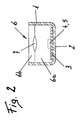
- Fig. 1 a three-dimensional view of a lighting fixture and Fig. 2 a section through the structural design.
- Fig. 1 is a lighting fixture for outdoor lighting shown outdoors.
- a metal core plate 3 with direct heat transfer is arranged on the bottom surface 2.
- LEDs 4 so-called LED are arranged in the direction of the light exit opening.
- the LEDs have integrated electronics 5, in particular control electronics for preferably each light-emitting diode 4.
- the light-emitting diode 4 or light-emitting diodes are high-performance light-emitting diode with a lens arranged directly.
- the assembly of the LED can be different colors, according to customer requirements.
- an LED spotlight with three primary optic LEDs and an emission angle of 40 ° can be produced.
- Mainly a nominal supply voltage of 24 V will be used.
- the rated power of the lighting fixture can be 3.5 to 9.2 W.
- the activation of the LEDs 4 is preferably carried out via a pulse width modulation signal.
- the structure namely metal core board 3, LED 4 and light-emitting diodes with their electronics 5, are clearly surmounted by the side surfaces of the trough-shaped metal housing 1.
- This structure is with a - in the Fig. 1 not shown visible - potting compound 6 in the metal housing 1 moisture-proof and completely potted. A minimum degree of protection of IP 65 can easily be achieved.
- fastening means 9 for fixtures 8 can be provided on the metal housing 1, arranged on the outside.
- the lighting fixture can preferably be recessed with its metal housing 1 also in sidewalks or lanes. An exemplary application would be to install this lighting fixture in front of railroad crossings to increase safety.
- the lighting fixture could also be mounted on bridges for visual enrichment of a cityscape.
- the completely encapsulated lighting fixture is encapsulated watertight and defies all imaginable weather conditions. Even intense sunlight leads to no damage, since the potting compound 6 compensates as elastic mass all thermal expansions.
- the metal core board 3 arranged with a direct heat transfer.
- the contact surface of the metal core board 3 is provided with the metal housing 1 with a thermal paste or a heat conducting foil.
- the electrical connections for the electronics 5 and the light emitting diode 4 or light emitting diodes are - in the Fig. 2 not shown - in the area of the contact surface metal core board 3 and metal housing 1 via a mounting screw led to the outside.
- the electronics 5, in particular the control electronics, comprises a temperature sensor (not shown) which detects the temperature of the hot spot location of the light-emitting diode 4 indirectly. Furthermore, the electronics 5, in particular the control electronics, a - also not shown - current controller with a dimming function, the current controller is controlled by the temperature sensor.
- This structure namely the metal core board 3, the light emitting diode 4 or LEDs with their electronics 5, as already mentioned, clearly surmounted by the side surfaces of the trough-shaped metal housing 1 and this Structure is moisture-proof and completely potted with a potting compound 6 in the metal housing 1.
- the casting compound 6 is in particular a cold casting system, preferably an elastomeric polyurethane consisting essentially of isocyanate and polyol.
- the potting compound 6 is also lightfast, optically neutral and waterproof.
- the casting is designed as a double-shell casting.
- a potting 6a with a polyurethane-based potting compound with low Shore hardness, for example 40 to 70 Sh.A and in the light exit opening a potting 6b with a polyurethane-based potting compound with a high shore Hardness, for example, 30 to 80 Sh.D provided.
- a system potting is possible, which is completely elastic on the one hand in the area of the LED and on the other hand has a hard surface. It is entirely within the scope of the possible that the surface of the potting compound 6 is cleaned by means of high-pressure cleaner and a treatment by means of sandblasting with a pressure of 7 bar, during a period of 30 seconds, without destruction resists.
- the potting is formed in the region of its transition from hard to soft as a secondary lens 7 for focusing the light.
- This zone is produced in particular by the shape of the potting compound and the type of composition of the potting compound 6.
Landscapes
- Engineering & Computer Science (AREA)
- General Engineering & Computer Science (AREA)
- Arrangement Of Elements, Cooling, Sealing, Or The Like Of Lighting Devices (AREA)
- Non-Portable Lighting Devices Or Systems Thereof (AREA)
Abstract
Description
- Die Erfindung betrifft einen Beleuchtungskörper, insbesondere für eine Außenbeleuchtung im Freien, die mindestens eine, vorzugsweise mehrere, Leuchtdioden mit einer Elektronik, insbesondere einer Steuerelektronik für vorzugsweise jede Leuchtdiode, umfasst.
- Aus der
EP 1 876 646 A2 ist eine LED-Leuchte mit integrierter Elektronik zur Ansteuerung der LED's bekannt. Diese Leuchte ist für beengte, gegebenenfalls feuchte, Raumverhältnisse, wie Stallungen oder Käfige vorgesehen. Bei dieser Leuchte sind die LED in einem Gehäuse vorgesehen, wobei die Elektronik in dem Gehäuse vergossen wird. Als Alternative kann die Elektronik mit der montierten LED ohne Verwendung eines Gehäuses in Kunstharz vergossen werden. Nachteilig bei dieser Leuchte ist, dass eine genügende Wärmeabfuhr nicht gewährleistet ist, wodurch die Lebenszeit der LED stark beeinträchtigt ist. - Ferner ist aus der
WO 98/11946 - Darüber hinaus ist aus der
EP 1 477 729 eine weitere Beleuchtungsvorrichtung für Geflügel-Haltungsanlagen bekannt, bei der einzelne Leuchten in verschiedenen Etagen benutzt werden. - Alle oben aufgezeigten Beleuchtungen finden jedoch in Räumen, auch wenn diese schmutz- und feuchtigkeitsbelastet sind, Verwendung.
- Die Aufgabe der Erfindung ist es, einen Beleuchtungskörper der eingangs genannten Art zu schaffen, der einerseits die obigen Nachteile vermeidet und der anderseits im Freien, mit allen Umwelteinflüssen und Belastungen, eingesetzt werden kann.
- Die Aufgabe wird durch die Erfindung gelöst.
- Der erfindungsgemäße Beleuchtungskörper ist dadurch gekennzeichnet, dass in einem wannenförmigen Metallgehäuse, vorzugsweise an dessen Boden- bzw. Grundfläche, eine Metallkernplatine am Metallgehäuses mit direktem Wärmeübergang angeordnet ist, dass auf der dem Metallgehäuse abgewandten Seite der Metallkernplatine die in Richtung der Lichtaustrittsöffnung weisende Leuchtdiode bzw. weisenden Leuchtdioden angeordnet ist bzw. sind und dass dieser Aufbau, nämlich Metallkernplatine, Leuchtdiode bzw. Leuchtdioden mit Elektronik, von den Seitenflächen des wannenförmigen Metallgehäuses deutlich überragt ist und mit einer, insbesondere auf Polyurethan-Basis basierenden, Vergussmasse in dem Metallgehäuse, insbesondere feuchtigkeitsdicht, vollständig vergossen ist. Mit der Erfindung ist es erstmals möglich einen Beleuchtungskörper mit LED's zu schaffen, der vollständig vergossen ist und somit in der freien Umwelt eingesetzt werden kann. Die Schutzart die dadurch erreicht wird ist mindestens IP 65. Ferner kann durch den vollständigen Verguss die Lichtaustrittsfläche belastet werden. So kann also der erfindungsgemäße Beleuchtungskörper auch in Gehwegen und Strassen eingebaut werden, wobei die Lichtaustrittsfläche einen Teil der begehbaren Fläche bzw. der Fahrbahn bildet. Die Wärmeabfuhr aus dem Inneren des Beleuchtungskörpers erfolgt über die Metallkernplatine in das Metallgehäuse.
- Wie ja an sich bekannt, sind LED sehr temperaturempfindlich. Bei kleinen Überschreitungen der maximalen Temperatur erfolgt eine eklatante Verkürzung der Lebensdauer. Mit dem erfindungsgemäßen Wärmeübergang von LED auf Metallkernplatine und Gehäuse ist die erforderliche Wärmeabfuhr aus dem Inneren gewährleistet.
- Nach einer Ausgestaltung der Erfindung ist die Leuchtdiode eine Hochleistungs-Leuchtdiode mit direkt angeordneter Linse. In vorteilhafterweise können Hochleistungs-LED's Verwendung finden, das sind Lichtquellen mit hoher Lichtausbeute bei geringen Platzbedarf.
- Gemäß einer weiteren Ausgestaltung der Erfindung ist die Kontaktfläche der Metallkernplatine mit dem Metallgehäuse mit einer Wärmeleitpaste oder einer Wärmeleitfolie versehen. Dadurch kann der Wärmeübergang noch besser gestaltet und sichergestellt werden.
- Nach einer Weiterbildung der Erfindung sind die Anschlüsse für die Elektronik und die Leuchtdiode bzw. Leuchtdioden im Bereich der Kontaktfläche Metallkernplatine und Metallgehäuse über eine Anbauverschraubung nach außen geführt. Mit einer derartigen Anschlusseinrichtung kann in vorteilhafterweise die Wasserdichtheit gewährleistet werden.
- Gemäß einem besonderen Merkmal der Erfindung weist die Elektronik, insbesondere die Steuerelektronik, einen Temperatursensor auf, der die Temperatur der Hot-Spot-Stelle der Leuchtdiode indirekt erfasst. Dadurch ist es möglich, eine Kontrolle über die im Betrieb herrschende Temperatur nahe der Lichtquelle zu erlangen.
- Nach einem weiteren besonderen Merkmal der Erfindung umfasst die Elektronik, insbesondere die Steuerelektronik, einen Stromregler mit vorzugsweiser Dimmfunktion, wobei der Stromregler vom Temperatursensor angesteuert ist. Durch diesen Einsatz der Elektronik mit der thermischen Überwachung der LEDs ist eine Leistungserhöhung möglich, ohne dass ein Einfluss auf die Lebensdauer gegeben ist.
- Gemäß einer besonderen Ausgestaltung der Erfindung sind die Elektroniken miteinander verbunden und an einen Stromregler mit Dimmfunktion angeschlossen, wobei der Stromregler von den Temperatursensoren angesteuert ist. Die Dimmfunktion ist derart konzipiert, dass bei Überschreiten der maximalen Temperatur eines Hot-Spot Temperatursensors das gesamte Beleuchtungssystem geregelt wird. Man kann das System derart regeln, dass es praktisch zu keinen Helligkeitsunterschieden der geregelten LEDs kommt. Alle Leuchtdioden eines Systems werden auf die gleichen Helligkeitswerte geregelt, da unterschiedliche Helligkeitswerte manchmal sehr unangenehm empfunden werden können. Anderseits kann die Regelung derart gestaltet werden, dass bei Verwendung von Farb-LED's gewünschte Lichtfarben und Strahlungsintensitäten erreicht werden.
- Nach einem weiteren Merkmal der Erfindung ist die Vergussmasse lichtecht, optisch neutral und wasserdicht. Insbesondere ist es vorteilhaft, dass die Vergussmasse UV-beständig ist.
- Gemäß einem weiteren besonderen Merkmal der Erfindung ist die Vergussmasse ein Gießsystem, insbesondere ein Kaltgießsystem, vorzugsweise ein elastomeres Polyurethan, bestehend im Wesentlichen aus Isocyanat und Polyol. Eine derartige Vergussmasse hat bei den Versuchen Ergebnisse gezeigt, die den Entwicklungsvorgaben vollends entsprochen hat. Insbesondere verursachen die Materialausdehnungen keine Beschädigung der elektronischen Komponenten im Inneren.
- Nach einer besonderen Weiterbildung der Erfindung ist der Verguss als zweischaliger Verguss ausgeführt, wobei im Bereich der Leuchtdiode ein Verguss mit einer auf Polyurethan-Basis bestehenden Vergussmasse mit geringer Shore-Härte, beispielsweise 40 bis 70 Sh.A, und im Bereich der Lichtaustrittsöffnung ein Verguss mit einer auf Polyurethan-Basis bestehenden Vergussmasse mit hoher Shore-Härte, beispielsweise 30 bis 80 Sh.D, vorgesehen ist. Mit dieser Vergusstechnik ist ein Systemverguss möglich, der einerseits komplett elastisch und trotzdem eine harte Oberfläche aufweisen kann.
- Gemäß einem ganz besonderen Merkmal der Erfindung weist der Verguss im Bereich seines Überganges von hart auf weich eine als Sekundärlinse für eine Fokussierung des Lichtes ausgebildete Zone auf, die insbesondere durch Form des Vergusses und die Art der Zusammensetzung der Vergussmasse gegeben ist. Durch diese Sekundärlinse können optische Effekte erreicht werden, beispielsweise eine Umlenkung der Leuchtrichtung oder eine asymmetrische Lichtführung. Auf Grund der Geometrie der Sekundärlinse können also die Lichtstrahlen entsprechend beeinflusst bzw. gelenkt werden.
- Die Erfindung wird an Hand eines Ausführungsbeispieles, das in der Zeichnung dargestellt ist, näher erläutert.
-
Fig. 1 eine dreidimensionale Ansicht eines Beleuchtungskörpers undFig. 2 einen Schnitt durch den konstruktiven Aufbau. - Gemäß der
Fig. 1 ist ein Beleuchtungskörper für eine Außenbeleuchtung im Freien dargestellt. In einem wannenförmigen Metallgehäuse 1 ist an dessen Bodenfläche 2 eine Metallkernplatine 3 mit direktem Wärmeübergang angeordnet. Auf der Metallkernplatine 3 sind in Richtung der Lichtaustrittsöffnung Leuchtdioden 4, so genannte LED, angeordnet. Die LED's weisen eine integrierte Elektronik 5, insbesondere eine Steuerelektronik für vorzugsweise jede Leuchtdiode 4 auf. Die Leuchtdiode 4 bzw. Leuchtdioden sind Hochleistungs-Leuchtdiode mit direkt angeordneter Linse. - Natürlich kann die Bestückung der LED verschiedenfarbig, nach Kundenwunsch, erfolgen. Bevorzugt kann ein LED-Strahler mit drei primäroptik-LED's und einem Abstrahlungswinkel von 40° hergestellt werden. Vorwiegend wird eine Nennversorgungsspannung von 24 V zum Einsatz kommen. Entsprechend dem Einsatz von Farb-LED's kann die Nennleistung des Beleuchtungskörpers bei 3,5 bis 9,2 W liegen. Die Ansteuerung der Leuchtdioden 4 erfolgt vorzugsweise über ein Pulsweitenmodulations-Signal.
- Bei einem Einsatz von LED mit der Lichtfarbe rot, gelb, blau und grün kann eine überaus große Farbpalette an Licht erzeugt werden. Denkbare resultierende Farben sind beispielsweise stahlblau oder weinrot.
- Der Aufbau, nämlich Metallkernplatine 3, Leuchtdiode 4 bzw. Leuchtdioden mit ihrer Elektronik 5, werden von den Seitenflächen des wannenförmigen Metallgehäuses 1 deutlich überragt. Dieser Aufbau wird mit einer - in der
Fig. 1 nicht sichtbar dargestellten - Vergussmasse 6 in dem Metallgehäuse 1 feuchtigkeitsdicht und vollständig vergossen. Eine Mindestschutzart von IP 65 kann problemlos erreicht werden. - Zur Befestigung des Beleuchtungskörpers im Freien können am Metallgehäuse 1, außen angeordnete, Befestigungsmittel 9 für Halterungen 8 vorgesehen werden. Der Beleuchtungskörper kann mit seinem Metallgehäuse 1 jedoch vorzugsweise auch in Gehwegen oder Fahrbahnen versenkt eingebaut werden. Eine beispielhafte Anwendung wäre es, diesen Beleuchtungskörper vor Bahnübergängen in die Strasse einzubauen, um die Sicherheit zu erhöhen.
- Natürlich könnte der Beleuchtungskörper auch an Brücken zur optischen Bereicherung eines Stadtbildes montiert werden.
- Der komplett vergossene Beleuchtungskörper ist wasserdicht gekapselt und trotzt allen erdenklichen Witterungseinflüssen. Auch eine intensive Sonneneinstrahlung führt zu keinen Schädigungen, da die Vergussmasse 6 als elastische Masse alle Wärmeausdehnungen ausgleicht.
- Gemäß der
Fig. 2 ist in dem wannenförmigen Metallgehäuse 1 die Metallkernplatine 3 mit einem direkten Wärmeübergang angeordnet. Für einen noch besseren Wärmeübergang ist die Kontaktfläche der Metallkernplatine 3 mit dem Metallgehäuse 1 mit einer Wärmeleitpaste oder einer Wärmeleitfolie versehen. Die elektrischen Anschlüsse für die Elektronik 5 und die Leuchtdiode 4 bzw. Leuchtdioden sind - in derFig. 2 nicht dargestellt - im Bereich der Kontaktfläche Metallkernplatine 3 und Metallgehäuse 1 über eine Anbauverschraubung nach außen geführt. - Die Elektronik 5, insbesondere die Steuerelektronik, umfasst einen - nicht dargestellten - Temperatursensor, der die Temperatur der Hot-Spot-Stelle der Leuchtdiode 4 indirekt erfasst. Weiters umfasst die Elektronik 5, insbesondere die Steuerelektronik, einen - ebenfalls nicht dargestellten - Stromregler mit einer Dimmfunktion, wobei der Stromregler vom Temperatursensor angesteuert wird.
- Dieser Aufbau, nämlich die Metallkernplatine 3, die Leuchtdiode 4 bzw. Leuchtdioden mit ihrer Elektronik 5, werden, wie bereits erwähnt, von den Seitenflächen des wannenförmigen Metallgehäuses 1 deutlich überragt und dieser Aufbau wird mit einer Vergussmasse 6 in dem Metallgehäuse 1 feuchtigkeitsdicht und vollständig vergossen.
- Die Vergussmasse 6 ist insbesondere ein Kaltgießsystem, vorzugsweise ein elastomeres Polyurethan, bestehend im Wesentlichen aus Isocyanat und Polyol. Die Vergussmasse 6 ist ferner lichtecht, optisch neutral und wasserdicht.
- Für besondere Verwendungszwecke des Beleuchtungskörpers ist der Verguss als zweischaliger Verguss ausgeführt. Im Bereich der Leuchtdiode 4 ist ein Verguss 6a mit einer auf Polyurethan-Basis bestehenden Vergussmasse mit geringer Shore-Härte, beispielsweise 40 bis 70 Sh.A, und im Bereich der Lichtaustrittsöffnung ein Verguss 6b mit einer auf Polyurethan-Basis bestehenden Vergussmasse mit hoher Shore-Härte, beispielsweise 30 bis 80 Sh.D, vorgesehen. Mit dieser Vergusstechnik ist ein Systemverguss möglich, der einerseits im Bereich der LED komplett elastisch ist und der anderseits eine harte Oberfläche aufweist. Es ist durchaus im Bereich des Möglichen, dass die Oberfläche der Vergussmasse 6 mittels Hochdruckreiniger gereinigt wird und einr Behandlung mittels Sandstrahlen mit einem Druck von 7 bar, während einer Zeit von 30 Sekunden, ohne Zerstörung widersteht.
- Für ganz spezielle Verwendungszwecke und optische Effekte, beispielsweise eine Umlenkung der Leuchtrichtung oder eine asymmetrische Lichtführung, ist der Verguss im Bereich seines Überganges von hart auf weich als Sekundärlinse 7 für eine Fokussierung des Lichtes ausgebildet. Diese Zone wird insbesondere durch die Form des Vergusses und die Art der Zusammensetzung der Vergussmasse 6 hergestellt.
Claims (11)
- Beleuchtungskörper, insbesondere für eine Außenbeleuchtung im Freien, die mindestens eine, vorzugsweise mehrere, Leuchtdioden mit einer Elektronik, insbesondere einer Steuerelektronik für vorzugsweise jede Leuchtdiode, umfasst, dadurch gekennzeichnet, dass in einem wannenförmigen Metallgehäuse (1), vorzugsweise an dessen Boden- (2) bzw. Grundfläche, eine Metallkernplatine (3) am Metallgehäuses (1) mit direktem Wärmeübergang angeordnet ist, dass auf der dem Metallgehäuse(1) abgewandten Seite der Metallkernplatine (3) die in Richtung der Lichtaustrittsöffnung weisende Leuchtdiode (4) bzw. weisenden Leuchtdioden angeordnet ist bzw. sind und dass dieser Aufbau, nämlich Metallkernplatine (3), Leuchtdiode (4) bzw. Leuchtdioden mit Elektronik (5), von den Seitenflächen des wannenförmigen Metallgehäuses (1) deutlich überragt ist und mit einer, insbesondere auf Polyurethan-Basis basierenden, Vergussmasse (6) in dem Metallgehäuse (1), insbesondere feuchtigkeitsdicht, vollständig vergossen ist.
- Beleuchtung nach Anspruch 1, dadurch gekennzeichnet, dass die Leuchtdiode (4) eine Hochleistungs-Leuchtdiode mit direkt angeordneter Linse ist.
- Beleuchtung nach Anspruch 1 oder 2, dadurch gekennzeichnet, dass die Kontaktfläche der Metallkernplatine (3) mit dem Metallgehäuse (1) mit einer Wärmeleitpaste oder einer Wärmeleitfolie versehen ist.
- Beleuchtung nach einem der Ansprüche 1 bis 3, dadurch gekennzeichnet, dass die Anschlüsse für die Elektronik (5) und die Leuchtdiode (4) bzw. Leuchtdioden im Bereich der Kontaktfläche Metallkernplatine (3) und Metallgehäuse (1) über eine Anbauverschraubung nach außen geführt sind.
- Beleuchtung nach einem der Ansprüche 1 bis 4, dadurch gekennzeichnet, dass die Elektronik (5), insbesondere die Steuerelektronik, einen Temperatursensor aufweist, der die Temperatur der Hot-Spot-Stelle der Leuchtdiode (4) indirekt erfasst.
- Beleuchtung nach einem der Ansprüche 1 bis 5, dadurch gekennzeichnet, dass die Elektronik (5), insbesondere die Steuerelektronik, einen Stromregler mit vorzugsweiser Dimmfunktion umfasst, wobei der Stromregler vom Temperatursensor angesteuert ist.
- Beleuchtung nach einem der Ansprüche 1 bis 6, dadurch gekennzeichnet, dass die Elektroniken (5) miteinander verbunden sind und an einen Stromregler mit Dimmfunktion angeschlossen sind, wobei der Stromregler von den Temperatursensoren angesteuert ist.
- Beleuchtung nach einem der Ansprüche 1 bis 7, dadurch gekennzeichnet, dass die Vergussmasse (6) lichtecht, optisch neutral und wasserdicht ist.
- Beleuchtung nach einem der Ansprüche 1 bis 8, dadurch gekennzeichnet, dass die Vergussmasse (6) ein Gießsystem, insbesondere ein Kaltgießsystem, vorzugsweise ein elastomeres Polyurethan, bestehend im Wesentlichen aus Isocyanat und Polyol, ist
- Beleuchtung nach einem der Ansprüche 1 bis 9, dadurch gekennzeichnet, dass der Verguss als zweischaliger Verguss ausgeführt ist, wobei im Bereich der Leuchtdiode ein Verguss (6a) mit einer auf Polyurethan-Basis bestehenden Vergussmasse mit geringer Shore-Härte, beispielsweise 40 bis 70 Sh.A, und im Bereich der Lichtaustrittsöffnung ein Verguss (6b) mit einer auf Polyurethan-Basis bestehenden Vergussmasse mit hoher Shore-Härte, beispielsweise 30 bis 80 Sh.D, vorgesehen ist.
- Beleuchtung nach Anspruch 10, dadurch gekennzeichnet, dass der Verguss im Bereich seines Überganges von hart auf weich eine als Sekundärlinse (7) für eine Fokussierung des Lichtes ausgebildete Zone aufweist, die insbesondere durch Form des Vergusses und die Art der Zusammensetzung der Vergussmasse gegeben ist.
Applications Claiming Priority (1)
| Application Number | Priority Date | Filing Date | Title |
|---|---|---|---|
| ATA202/2008A AT506384B1 (de) | 2008-02-07 | 2008-02-07 | Beleuchtungskörper |
Publications (2)
| Publication Number | Publication Date |
|---|---|
| EP2088369A1 true EP2088369A1 (de) | 2009-08-12 |
| EP2088369B1 EP2088369B1 (de) | 2015-04-08 |
Family
ID=40506498
Family Applications (1)
| Application Number | Title | Priority Date | Filing Date |
|---|---|---|---|
| EP09001605.6A Not-in-force EP2088369B1 (de) | 2008-02-07 | 2009-02-05 | Beleuchtungskörper |
Country Status (2)
| Country | Link |
|---|---|
| EP (1) | EP2088369B1 (de) |
| AT (1) | AT506384B1 (de) |
Cited By (9)
| Publication number | Priority date | Publication date | Assignee | Title |
|---|---|---|---|---|
| CH701962A1 (de) * | 2009-10-05 | 2011-04-15 | Staub Designlight Ag | Beleuchtungseinrichtung und Lampe für diese. |
| EP2416064A1 (de) * | 2010-08-06 | 2012-02-08 | FHF Funke + Huster Fernsig GmbH | Elektrische Signal-Schaltungsanordnung, vorzugsweise elektrische Signal-Leuchtenanordnung |
| DE202011000999U1 (de) * | 2011-04-28 | 2012-07-30 | Zumtobel Lighting Gmbh | Außenleuchte zur Beleuchtung einer Gebäudefläche |
| DE102011083273A1 (de) * | 2011-09-23 | 2013-03-28 | Zumtobel Lighting Gmbh | Leuchte, insbesondere Feuchtraumleuchte, mit verbesserter Dichtung |
| WO2013189992A1 (de) * | 2012-06-21 | 2013-12-27 | Zumtobel Lighting Gmbh | Leuchte, insbesondere feuchtraumleuchte |
| NO20150809A1 (en) * | 2015-06-19 | 2016-12-20 | Willy Kronborg | Light weight oxygen free lamp assembly and method for fabrication of same |
| EP3757455A1 (de) * | 2019-06-24 | 2020-12-30 | A1 Mobile Light Technology GmbH | Regelbare lampe |
| EP3825604A1 (de) * | 2019-11-25 | 2021-05-26 | Zumtobel Lighting GmbH | Lichtemittierende anordnung |
| WO2024223863A1 (en) * | 2023-04-28 | 2024-10-31 | Ledtechnic Bv | Luminaire for outdoor use, method of its manufacture and use of a luminaire in a paved surface |
Families Citing this family (1)
| Publication number | Priority date | Publication date | Assignee | Title |
|---|---|---|---|---|
| DE202012104635U1 (de) * | 2012-11-29 | 2014-03-03 | Zumtobel Lighting Gmbh | Leuchte mit einem Leuchtengehäuse und elektronischer Schaltung |
Citations (10)
| Publication number | Priority date | Publication date | Assignee | Title |
|---|---|---|---|---|
| WO1998011946A1 (en) | 1996-09-19 | 1998-03-26 | O.L.T. Ltd. | Apparatus and method for enhancing fowl productivity |
| WO2003089841A1 (en) * | 2002-04-20 | 2003-10-30 | Ewington Christopher James | Lighting module |
| EP1477729A1 (de) | 2003-05-13 | 2004-11-17 | Christopher David | Beleuchtungsvorrichtung für Haltungsanlagen für Geflügel |
| DE102004015730A1 (de) * | 2004-03-29 | 2005-11-03 | Regiolux Gmbh | Lichtschiene zum flächenbündigen Einbau in eine Fahr- oder Verkehrsfläche |
| US20060012991A1 (en) * | 2004-07-15 | 2006-01-19 | Gelcore, Llc | Led lighting system with reflective board |
| WO2007013121A1 (en) * | 2005-07-28 | 2007-02-01 | Immobiliare Eder S.R.L. | Led-based lighting device for ground, wall, floor and road surface mounting |
| US20070058377A1 (en) | 2005-09-15 | 2007-03-15 | Zampini Thomas L Ii | Interconnection arrangement having mortise and tenon connection features |
| US20070183156A1 (en) * | 2006-02-09 | 2007-08-09 | Led Smart Inc. | LED lighting system |
| WO2007131123A2 (en) | 2006-05-03 | 2007-11-15 | Dialight Corporation | Embedded led light source |
| EP1876646A2 (de) | 2006-07-07 | 2008-01-09 | Rütsche Technik GmbH | LED-Leuchte |
Family Cites Families (6)
| Publication number | Priority date | Publication date | Assignee | Title |
|---|---|---|---|---|
| CA2386224A1 (en) * | 1999-10-04 | 2001-04-12 | J. Marc Hutchins | Elongated light emitting diode lighting system |
| US7262752B2 (en) * | 2001-01-16 | 2007-08-28 | Visteon Global Technologies, Inc. | Series led backlight control circuit |
| US7118251B1 (en) * | 2003-05-23 | 2006-10-10 | Ilight Technologies, Inc. | Illumination device for simulating channel letters |
| EP1711737B1 (de) * | 2004-01-28 | 2013-09-18 | Koninklijke Philips Electronics N.V. | Abgedichtete gehäuseeinheit für beleuchtungssystem |
| WO2006056066A1 (en) * | 2004-11-29 | 2006-06-01 | Tir Systems Ltd. | Integrated modular lighting unit |
| KR100516123B1 (ko) * | 2005-08-30 | 2005-09-21 | 주식회사 누리플랜 | 라인형 엘이디 조명등 |
-
2008
- 2008-02-07 AT ATA202/2008A patent/AT506384B1/de not_active IP Right Cessation
-
2009
- 2009-02-05 EP EP09001605.6A patent/EP2088369B1/de not_active Not-in-force
Patent Citations (10)
| Publication number | Priority date | Publication date | Assignee | Title |
|---|---|---|---|---|
| WO1998011946A1 (en) | 1996-09-19 | 1998-03-26 | O.L.T. Ltd. | Apparatus and method for enhancing fowl productivity |
| WO2003089841A1 (en) * | 2002-04-20 | 2003-10-30 | Ewington Christopher James | Lighting module |
| EP1477729A1 (de) | 2003-05-13 | 2004-11-17 | Christopher David | Beleuchtungsvorrichtung für Haltungsanlagen für Geflügel |
| DE102004015730A1 (de) * | 2004-03-29 | 2005-11-03 | Regiolux Gmbh | Lichtschiene zum flächenbündigen Einbau in eine Fahr- oder Verkehrsfläche |
| US20060012991A1 (en) * | 2004-07-15 | 2006-01-19 | Gelcore, Llc | Led lighting system with reflective board |
| WO2007013121A1 (en) * | 2005-07-28 | 2007-02-01 | Immobiliare Eder S.R.L. | Led-based lighting device for ground, wall, floor and road surface mounting |
| US20070058377A1 (en) | 2005-09-15 | 2007-03-15 | Zampini Thomas L Ii | Interconnection arrangement having mortise and tenon connection features |
| US20070183156A1 (en) * | 2006-02-09 | 2007-08-09 | Led Smart Inc. | LED lighting system |
| WO2007131123A2 (en) | 2006-05-03 | 2007-11-15 | Dialight Corporation | Embedded led light source |
| EP1876646A2 (de) | 2006-07-07 | 2008-01-09 | Rütsche Technik GmbH | LED-Leuchte |
Cited By (12)
| Publication number | Priority date | Publication date | Assignee | Title |
|---|---|---|---|---|
| CH701962A1 (de) * | 2009-10-05 | 2011-04-15 | Staub Designlight Ag | Beleuchtungseinrichtung und Lampe für diese. |
| EP2416064A1 (de) * | 2010-08-06 | 2012-02-08 | FHF Funke + Huster Fernsig GmbH | Elektrische Signal-Schaltungsanordnung, vorzugsweise elektrische Signal-Leuchtenanordnung |
| DE202011000999U1 (de) * | 2011-04-28 | 2012-07-30 | Zumtobel Lighting Gmbh | Außenleuchte zur Beleuchtung einer Gebäudefläche |
| CN103492795A (zh) * | 2011-04-28 | 2014-01-01 | 宗拓贝尔照明器材有限公司 | 用于建筑物表面照明的外部照明装置 |
| DE102011083273A1 (de) * | 2011-09-23 | 2013-03-28 | Zumtobel Lighting Gmbh | Leuchte, insbesondere Feuchtraumleuchte, mit verbesserter Dichtung |
| WO2013189992A1 (de) * | 2012-06-21 | 2013-12-27 | Zumtobel Lighting Gmbh | Leuchte, insbesondere feuchtraumleuchte |
| NO20150809A1 (en) * | 2015-06-19 | 2016-12-20 | Willy Kronborg | Light weight oxygen free lamp assembly and method for fabrication of same |
| WO2016204627A1 (en) * | 2015-06-19 | 2016-12-22 | Willy Kronborg | Light weight oxygen free lamp assembly and method for fabrication of same |
| EP3757455A1 (de) * | 2019-06-24 | 2020-12-30 | A1 Mobile Light Technology GmbH | Regelbare lampe |
| EP3825604A1 (de) * | 2019-11-25 | 2021-05-26 | Zumtobel Lighting GmbH | Lichtemittierende anordnung |
| WO2024223863A1 (en) * | 2023-04-28 | 2024-10-31 | Ledtechnic Bv | Luminaire for outdoor use, method of its manufacture and use of a luminaire in a paved surface |
| BE1031564B1 (nl) * | 2023-04-28 | 2024-12-02 | Ledtechnic Bvba | Verlichtingsarmatuur voor buitengebruik, werkwijze voor vervaardiging ervan en gebruik van een verlichtingsarmatuur in een verhard oppervlak |
Also Published As
| Publication number | Publication date |
|---|---|
| EP2088369B1 (de) | 2015-04-08 |
| AT506384B1 (de) | 2013-05-15 |
| AT506384A1 (de) | 2009-08-15 |
Similar Documents
| Publication | Publication Date | Title |
|---|---|---|
| EP2088369B1 (de) | Beleuchtungskörper | |
| DE202010018238U1 (de) | LED-Beleuchtung für die Nutztierhaltung | |
| EP1872624A1 (de) | Led-modul und led-beleuchtungseinrichtung mit mehreren led-modulen | |
| DE102009008845A1 (de) | Leuchtmodul und Verfahren zum Herstellen eines Leuchtmoduls | |
| EP2270387B1 (de) | LED Flachleuchte | |
| EP2454521B1 (de) | Elektrische leuchte | |
| DE102011076128A1 (de) | Trägersystem und Lichtmodul zur Befestigung daran | |
| DE202011108542U1 (de) | Leuchte, insbesondere Wand- und/oder Deckenleuchte | |
| DE102010045297A1 (de) | Leuchte, insbesondere Tunnelleuchte | |
| EP2350522A1 (de) | Led-beleuchtungsvorrichtung, insbesondere für tunnels | |
| EP2761114B1 (de) | Wasserbecken mit beleuchteten randsteinen | |
| EP1876646A2 (de) | LED-Leuchte | |
| DE19818403A1 (de) | Beleuchtungssystem mit Niederspannungs-Leuchten und -Lampen | |
| DE20104098U1 (de) | Effektleuchte zur Unterwasserbeleuchtung von Whirlwannen, Pools u.dgl. | |
| WO2014161664A1 (de) | Led-modul, leuchte mit einem solchen und verfahren zur beeinflussung eines lichtspektrums | |
| DE202010010263U1 (de) | Beleuchtungseinrichtung, insbesondere für einen Außenbereich | |
| DE102016104342B4 (de) | Beleuchtungsmodul und Straßen- oder Wegleuchte | |
| EP2051004B1 (de) | Beleuchtung, insbesondere für Schaufenster oder Ausstellungsvitrinen | |
| DE102005016363A1 (de) | Leuchte mit LED und Verfahren zum Betrieb der Leuchte | |
| CH701962A1 (de) | Beleuchtungseinrichtung und Lampe für diese. | |
| DE202010014942U1 (de) | Leuchte für Tierhaltungsanlagen | |
| DE102008022414A1 (de) | Leuchtmittel zur Verwendung in einer Straßenbeleuchtung sowie eine Vorrichtung zur Straßenbeleuchtung | |
| DE102012017613A1 (de) | Lichtmodul für den Einsatz im Nassbereich | |
| DE102015115947A1 (de) | Unterwasserscheinwerfer | |
| DE20006022U1 (de) | Leuchteinrichtung mit einem Sockel |
Legal Events
| Date | Code | Title | Description |
|---|---|---|---|
| PUAI | Public reference made under article 153(3) epc to a published international application that has entered the european phase |
Free format text: ORIGINAL CODE: 0009012 |
|
| AK | Designated contracting states |
Kind code of ref document: A1 Designated state(s): AT BE BG CH CY CZ DE DK EE ES FI FR GB GR HR HU IE IS IT LI LT LU LV MC MK MT NL NO PL PT RO SE SI SK TR |
|
| AX | Request for extension of the european patent |
Extension state: AL BA RS |
|
| 17P | Request for examination filed |
Effective date: 20100202 |
|
| 17Q | First examination report despatched |
Effective date: 20100308 |
|
| AKX | Designation fees paid |
Designated state(s): AT BE BG CH CY CZ DE DK EE ES FI FR GB GR HR HU IE IS IT LI LT LU LV MC MK MT NL NO PL PT RO SE SI SK TR |
|
| REG | Reference to a national code |
Ref country code: DE Ref legal event code: R079 Ref document number: 502009010861 Country of ref document: DE Free format text: PREVIOUS MAIN CLASS: F21V0031040000 Ipc: F21K0099000000 |
|
| GRAP | Despatch of communication of intention to grant a patent |
Free format text: ORIGINAL CODE: EPIDOSNIGR1 |
|
| RIC1 | Information provided on ipc code assigned before grant |
Ipc: F21V 15/01 20060101ALI20140901BHEP Ipc: F21V 31/04 20060101ALI20140901BHEP Ipc: F21V 29/00 20060101ALI20140901BHEP Ipc: F21K 99/00 20100101AFI20140901BHEP |
|
| INTG | Intention to grant announced |
Effective date: 20140919 |
|
| GRAS | Grant fee paid |
Free format text: ORIGINAL CODE: EPIDOSNIGR3 |
|
| GRAA | (expected) grant |
Free format text: ORIGINAL CODE: 0009210 |
|
| AK | Designated contracting states |
Kind code of ref document: B1 Designated state(s): AT BE BG CH CY CZ DE DK EE ES FI FR GB GR HR HU IE IS IT LI LT LU LV MC MK MT NL NO PL PT RO SE SI SK TR |
|
| REG | Reference to a national code |
Ref country code: GB Ref legal event code: FG4D Free format text: NOT ENGLISH |
|
| REG | Reference to a national code |
Ref country code: CH Ref legal event code: EP |
|
| REG | Reference to a national code |
Ref country code: IE Ref legal event code: FG4D Free format text: LANGUAGE OF EP DOCUMENT: GERMAN |
|
| REG | Reference to a national code |
Ref country code: AT Ref legal event code: REF Ref document number: 720863 Country of ref document: AT Kind code of ref document: T Effective date: 20150515 |
|
| REG | Reference to a national code |
Ref country code: DE Ref legal event code: R096 Ref document number: 502009010861 Country of ref document: DE Effective date: 20150521 |
|
| REG | Reference to a national code |
Ref country code: NL Ref legal event code: VDEP Effective date: 20150408 |
|
| REG | Reference to a national code |
Ref country code: LT Ref legal event code: MG4D |
|
| PG25 | Lapsed in a contracting state [announced via postgrant information from national office to epo] |
Ref country code: NL Free format text: LAPSE BECAUSE OF FAILURE TO SUBMIT A TRANSLATION OF THE DESCRIPTION OR TO PAY THE FEE WITHIN THE PRESCRIBED TIME-LIMIT Effective date: 20150408 |
|
| PG25 | Lapsed in a contracting state [announced via postgrant information from national office to epo] |
Ref country code: PT Free format text: LAPSE BECAUSE OF FAILURE TO SUBMIT A TRANSLATION OF THE DESCRIPTION OR TO PAY THE FEE WITHIN THE PRESCRIBED TIME-LIMIT Effective date: 20150810 Ref country code: LT Free format text: LAPSE BECAUSE OF FAILURE TO SUBMIT A TRANSLATION OF THE DESCRIPTION OR TO PAY THE FEE WITHIN THE PRESCRIBED TIME-LIMIT Effective date: 20150408 Ref country code: HR Free format text: LAPSE BECAUSE OF FAILURE TO SUBMIT A TRANSLATION OF THE DESCRIPTION OR TO PAY THE FEE WITHIN THE PRESCRIBED TIME-LIMIT Effective date: 20150408 Ref country code: ES Free format text: LAPSE BECAUSE OF FAILURE TO SUBMIT A TRANSLATION OF THE DESCRIPTION OR TO PAY THE FEE WITHIN THE PRESCRIBED TIME-LIMIT Effective date: 20150408 Ref country code: NO Free format text: LAPSE BECAUSE OF FAILURE TO SUBMIT A TRANSLATION OF THE DESCRIPTION OR TO PAY THE FEE WITHIN THE PRESCRIBED TIME-LIMIT Effective date: 20150708 Ref country code: FI Free format text: LAPSE BECAUSE OF FAILURE TO SUBMIT A TRANSLATION OF THE DESCRIPTION OR TO PAY THE FEE WITHIN THE PRESCRIBED TIME-LIMIT Effective date: 20150408 |
|
| PG25 | Lapsed in a contracting state [announced via postgrant information from national office to epo] |
Ref country code: GR Free format text: LAPSE BECAUSE OF FAILURE TO SUBMIT A TRANSLATION OF THE DESCRIPTION OR TO PAY THE FEE WITHIN THE PRESCRIBED TIME-LIMIT Effective date: 20150709 Ref country code: IS Free format text: LAPSE BECAUSE OF FAILURE TO SUBMIT A TRANSLATION OF THE DESCRIPTION OR TO PAY THE FEE WITHIN THE PRESCRIBED TIME-LIMIT Effective date: 20150808 Ref country code: LV Free format text: LAPSE BECAUSE OF FAILURE TO SUBMIT A TRANSLATION OF THE DESCRIPTION OR TO PAY THE FEE WITHIN THE PRESCRIBED TIME-LIMIT Effective date: 20150408 |
|
| REG | Reference to a national code |
Ref country code: DE Ref legal event code: R097 Ref document number: 502009010861 Country of ref document: DE |
|
| PG25 | Lapsed in a contracting state [announced via postgrant information from national office to epo] |
Ref country code: EE Free format text: LAPSE BECAUSE OF FAILURE TO SUBMIT A TRANSLATION OF THE DESCRIPTION OR TO PAY THE FEE WITHIN THE PRESCRIBED TIME-LIMIT Effective date: 20150408 Ref country code: DK Free format text: LAPSE BECAUSE OF FAILURE TO SUBMIT A TRANSLATION OF THE DESCRIPTION OR TO PAY THE FEE WITHIN THE PRESCRIBED TIME-LIMIT Effective date: 20150408 |
|
| PLBE | No opposition filed within time limit |
Free format text: ORIGINAL CODE: 0009261 |
|
| STAA | Information on the status of an ep patent application or granted ep patent |
Free format text: STATUS: NO OPPOSITION FILED WITHIN TIME LIMIT |
|
| PG25 | Lapsed in a contracting state [announced via postgrant information from national office to epo] |
Ref country code: PL Free format text: LAPSE BECAUSE OF FAILURE TO SUBMIT A TRANSLATION OF THE DESCRIPTION OR TO PAY THE FEE WITHIN THE PRESCRIBED TIME-LIMIT Effective date: 20150408 Ref country code: SK Free format text: LAPSE BECAUSE OF FAILURE TO SUBMIT A TRANSLATION OF THE DESCRIPTION OR TO PAY THE FEE WITHIN THE PRESCRIBED TIME-LIMIT Effective date: 20150408 Ref country code: RO Free format text: LAPSE BECAUSE OF NON-PAYMENT OF DUE FEES Effective date: 20150408 Ref country code: CZ Free format text: LAPSE BECAUSE OF FAILURE TO SUBMIT A TRANSLATION OF THE DESCRIPTION OR TO PAY THE FEE WITHIN THE PRESCRIBED TIME-LIMIT Effective date: 20150408 |
|
| 26N | No opposition filed |
Effective date: 20160111 |
|
| PG25 | Lapsed in a contracting state [announced via postgrant information from national office to epo] |
Ref country code: IT Free format text: LAPSE BECAUSE OF FAILURE TO SUBMIT A TRANSLATION OF THE DESCRIPTION OR TO PAY THE FEE WITHIN THE PRESCRIBED TIME-LIMIT Effective date: 20150408 |
|
| PGFP | Annual fee paid to national office [announced via postgrant information from national office to epo] |
Ref country code: DE Payment date: 20160218 Year of fee payment: 8 |
|
| PG25 | Lapsed in a contracting state [announced via postgrant information from national office to epo] |
Ref country code: SI Free format text: LAPSE BECAUSE OF FAILURE TO SUBMIT A TRANSLATION OF THE DESCRIPTION OR TO PAY THE FEE WITHIN THE PRESCRIBED TIME-LIMIT Effective date: 20150408 Ref country code: BE Free format text: LAPSE BECAUSE OF NON-PAYMENT OF DUE FEES Effective date: 20160229 |
|
| PG25 | Lapsed in a contracting state [announced via postgrant information from national office to epo] |
Ref country code: LU Free format text: LAPSE BECAUSE OF FAILURE TO SUBMIT A TRANSLATION OF THE DESCRIPTION OR TO PAY THE FEE WITHIN THE PRESCRIBED TIME-LIMIT Effective date: 20160205 Ref country code: MC Free format text: LAPSE BECAUSE OF FAILURE TO SUBMIT A TRANSLATION OF THE DESCRIPTION OR TO PAY THE FEE WITHIN THE PRESCRIBED TIME-LIMIT Effective date: 20150408 |
|
| REG | Reference to a national code |
Ref country code: CH Ref legal event code: PL |
|
| GBPC | Gb: european patent ceased through non-payment of renewal fee |
Effective date: 20160205 |
|
| PG25 | Lapsed in a contracting state [announced via postgrant information from national office to epo] |
Ref country code: LI Free format text: LAPSE BECAUSE OF NON-PAYMENT OF DUE FEES Effective date: 20160229 Ref country code: CH Free format text: LAPSE BECAUSE OF NON-PAYMENT OF DUE FEES Effective date: 20160229 |
|
| REG | Reference to a national code |
Ref country code: FR Ref legal event code: ST Effective date: 20161028 |
|
| REG | Reference to a national code |
Ref country code: IE Ref legal event code: MM4A |
|
| PG25 | Lapsed in a contracting state [announced via postgrant information from national office to epo] |
Ref country code: GB Free format text: LAPSE BECAUSE OF NON-PAYMENT OF DUE FEES Effective date: 20160205 Ref country code: FR Free format text: LAPSE BECAUSE OF NON-PAYMENT OF DUE FEES Effective date: 20160229 Ref country code: IE Free format text: LAPSE BECAUSE OF NON-PAYMENT OF DUE FEES Effective date: 20160205 |
|
| REG | Reference to a national code |
Ref country code: AT Ref legal event code: MM01 Ref document number: 720863 Country of ref document: AT Kind code of ref document: T Effective date: 20160205 |
|
| PG25 | Lapsed in a contracting state [announced via postgrant information from national office to epo] |
Ref country code: AT Free format text: LAPSE BECAUSE OF NON-PAYMENT OF DUE FEES Effective date: 20160205 |
|
| PG25 | Lapsed in a contracting state [announced via postgrant information from national office to epo] |
Ref country code: SE Free format text: LAPSE BECAUSE OF FAILURE TO SUBMIT A TRANSLATION OF THE DESCRIPTION OR TO PAY THE FEE WITHIN THE PRESCRIBED TIME-LIMIT Effective date: 20150408 |
|
| PG25 | Lapsed in a contracting state [announced via postgrant information from national office to epo] |
Ref country code: MT Free format text: LAPSE BECAUSE OF FAILURE TO SUBMIT A TRANSLATION OF THE DESCRIPTION OR TO PAY THE FEE WITHIN THE PRESCRIBED TIME-LIMIT Effective date: 20150408 |
|
| REG | Reference to a national code |
Ref country code: DE Ref legal event code: R119 Ref document number: 502009010861 Country of ref document: DE |
|
| PG25 | Lapsed in a contracting state [announced via postgrant information from national office to epo] |
Ref country code: DE Free format text: LAPSE BECAUSE OF NON-PAYMENT OF DUE FEES Effective date: 20170901 |
|
| PG25 | Lapsed in a contracting state [announced via postgrant information from national office to epo] |
Ref country code: HU Free format text: LAPSE BECAUSE OF FAILURE TO SUBMIT A TRANSLATION OF THE DESCRIPTION OR TO PAY THE FEE WITHIN THE PRESCRIBED TIME-LIMIT; INVALID AB INITIO Effective date: 20090205 Ref country code: CY Free format text: LAPSE BECAUSE OF FAILURE TO SUBMIT A TRANSLATION OF THE DESCRIPTION OR TO PAY THE FEE WITHIN THE PRESCRIBED TIME-LIMIT Effective date: 20150408 |
|
| PG25 | Lapsed in a contracting state [announced via postgrant information from national office to epo] |
Ref country code: MK Free format text: LAPSE BECAUSE OF FAILURE TO SUBMIT A TRANSLATION OF THE DESCRIPTION OR TO PAY THE FEE WITHIN THE PRESCRIBED TIME-LIMIT Effective date: 20150408 Ref country code: TR Free format text: LAPSE BECAUSE OF FAILURE TO SUBMIT A TRANSLATION OF THE DESCRIPTION OR TO PAY THE FEE WITHIN THE PRESCRIBED TIME-LIMIT Effective date: 20150408 |
|
| PG25 | Lapsed in a contracting state [announced via postgrant information from national office to epo] |
Ref country code: BG Free format text: LAPSE BECAUSE OF FAILURE TO SUBMIT A TRANSLATION OF THE DESCRIPTION OR TO PAY THE FEE WITHIN THE PRESCRIBED TIME-LIMIT Effective date: 20150408 |