EP2085684A1 - Leuchte mit selbsttragender Reflektoreinheit - Google Patents
Leuchte mit selbsttragender Reflektoreinheit Download PDFInfo
- Publication number
- EP2085684A1 EP2085684A1 EP09151603A EP09151603A EP2085684A1 EP 2085684 A1 EP2085684 A1 EP 2085684A1 EP 09151603 A EP09151603 A EP 09151603A EP 09151603 A EP09151603 A EP 09151603A EP 2085684 A1 EP2085684 A1 EP 2085684A1
- Authority
- EP
- European Patent Office
- Prior art keywords
- light
- luminaire according
- reflector unit
- lamp
- reflector
- Prior art date
- Legal status (The legal status is an assumption and is not a legal conclusion. Google has not performed a legal analysis and makes no representation as to the accuracy of the status listed.)
- Granted
Links
- 238000001816 cooling Methods 0.000 claims abstract description 6
- XAGFODPZIPBFFR-UHFFFAOYSA-N aluminium Chemical compound [Al] XAGFODPZIPBFFR-UHFFFAOYSA-N 0.000 claims description 4
- 229910052782 aluminium Inorganic materials 0.000 claims description 4
- 238000004512 die casting Methods 0.000 claims description 3
- 238000010422 painting Methods 0.000 claims description 3
- 238000007740 vapor deposition Methods 0.000 claims description 3
- 230000005855 radiation Effects 0.000 claims 1
- 230000015572 biosynthetic process Effects 0.000 description 2
- 238000005755 formation reaction Methods 0.000 description 2
- 238000005452 bending Methods 0.000 description 1
- 238000010276 construction Methods 0.000 description 1
- 230000001419 dependent effect Effects 0.000 description 1
- 238000011161 development Methods 0.000 description 1
- 230000018109 developmental process Effects 0.000 description 1
- 230000000694 effects Effects 0.000 description 1
- 238000004519 manufacturing process Methods 0.000 description 1
- 230000003287 optical effect Effects 0.000 description 1
- 230000003071 parasitic effect Effects 0.000 description 1
- 230000002093 peripheral effect Effects 0.000 description 1
- 239000004065 semiconductor Substances 0.000 description 1
- 230000007704 transition Effects 0.000 description 1
- 239000013585 weight reducing agent Substances 0.000 description 1
Images



Classifications
-
- F—MECHANICAL ENGINEERING; LIGHTING; HEATING; WEAPONS; BLASTING
- F21—LIGHTING
- F21V—FUNCTIONAL FEATURES OR DETAILS OF LIGHTING DEVICES OR SYSTEMS THEREOF; STRUCTURAL COMBINATIONS OF LIGHTING DEVICES WITH OTHER ARTICLES, NOT OTHERWISE PROVIDED FOR
- F21V23/00—Arrangement of electric circuit elements in or on lighting devices
- F21V23/02—Arrangement of electric circuit elements in or on lighting devices the elements being transformers, impedances or power supply units, e.g. a transformer with a rectifier
- F21V23/026—Fastening of transformers or ballasts
-
- F—MECHANICAL ENGINEERING; LIGHTING; HEATING; WEAPONS; BLASTING
- F21—LIGHTING
- F21S—NON-PORTABLE LIGHTING DEVICES; SYSTEMS THEREOF; VEHICLE LIGHTING DEVICES SPECIALLY ADAPTED FOR VEHICLE EXTERIORS
- F21S8/00—Lighting devices intended for fixed installation
- F21S8/02—Lighting devices intended for fixed installation of recess-mounted type, e.g. downlighters
-
- F—MECHANICAL ENGINEERING; LIGHTING; HEATING; WEAPONS; BLASTING
- F21—LIGHTING
- F21V—FUNCTIONAL FEATURES OR DETAILS OF LIGHTING DEVICES OR SYSTEMS THEREOF; STRUCTURAL COMBINATIONS OF LIGHTING DEVICES WITH OTHER ARTICLES, NOT OTHERWISE PROVIDED FOR
- F21V13/00—Producing particular characteristics or distribution of the light emitted by means of a combination of elements specified in two or more of main groups F21V1/00 - F21V11/00
- F21V13/02—Combinations of only two kinds of elements
-
- F—MECHANICAL ENGINEERING; LIGHTING; HEATING; WEAPONS; BLASTING
- F21—LIGHTING
- F21V—FUNCTIONAL FEATURES OR DETAILS OF LIGHTING DEVICES OR SYSTEMS THEREOF; STRUCTURAL COMBINATIONS OF LIGHTING DEVICES WITH OTHER ARTICLES, NOT OTHERWISE PROVIDED FOR
- F21V15/00—Protecting lighting devices from damage
- F21V15/01—Housings, e.g. material or assembling of housing parts
-
- F—MECHANICAL ENGINEERING; LIGHTING; HEATING; WEAPONS; BLASTING
- F21—LIGHTING
- F21V—FUNCTIONAL FEATURES OR DETAILS OF LIGHTING DEVICES OR SYSTEMS THEREOF; STRUCTURAL COMBINATIONS OF LIGHTING DEVICES WITH OTHER ARTICLES, NOT OTHERWISE PROVIDED FOR
- F21V29/00—Protecting lighting devices from thermal damage; Cooling or heating arrangements specially adapted for lighting devices or systems
- F21V29/50—Cooling arrangements
- F21V29/502—Cooling arrangements characterised by the adaptation for cooling of specific components
- F21V29/505—Cooling arrangements characterised by the adaptation for cooling of specific components of reflectors
-
- F—MECHANICAL ENGINEERING; LIGHTING; HEATING; WEAPONS; BLASTING
- F21—LIGHTING
- F21V—FUNCTIONAL FEATURES OR DETAILS OF LIGHTING DEVICES OR SYSTEMS THEREOF; STRUCTURAL COMBINATIONS OF LIGHTING DEVICES WITH OTHER ARTICLES, NOT OTHERWISE PROVIDED FOR
- F21V29/00—Protecting lighting devices from thermal damage; Cooling or heating arrangements specially adapted for lighting devices or systems
- F21V29/50—Cooling arrangements
- F21V29/502—Cooling arrangements characterised by the adaptation for cooling of specific components
- F21V29/507—Cooling arrangements characterised by the adaptation for cooling of specific components of means for protecting lighting devices from damage, e.g. housings
-
- F—MECHANICAL ENGINEERING; LIGHTING; HEATING; WEAPONS; BLASTING
- F21—LIGHTING
- F21S—NON-PORTABLE LIGHTING DEVICES; SYSTEMS THEREOF; VEHICLE LIGHTING DEVICES SPECIALLY ADAPTED FOR VEHICLE EXTERIORS
- F21S9/00—Lighting devices with a built-in power supply; Systems employing lighting devices with a built-in power supply
- F21S9/02—Lighting devices with a built-in power supply; Systems employing lighting devices with a built-in power supply the power supply being a battery or accumulator
- F21S9/022—Emergency lighting devices
-
- F—MECHANICAL ENGINEERING; LIGHTING; HEATING; WEAPONS; BLASTING
- F21—LIGHTING
- F21V—FUNCTIONAL FEATURES OR DETAILS OF LIGHTING DEVICES OR SYSTEMS THEREOF; STRUCTURAL COMBINATIONS OF LIGHTING DEVICES WITH OTHER ARTICLES, NOT OTHERWISE PROVIDED FOR
- F21V11/00—Screens not covered by groups F21V1/00, F21V3/00, F21V7/00 or F21V9/00
- F21V11/06—Screens not covered by groups F21V1/00, F21V3/00, F21V7/00 or F21V9/00 using crossed laminae or strips, e.g. grid-shaped louvers; using lattices or honeycombs
-
- F—MECHANICAL ENGINEERING; LIGHTING; HEATING; WEAPONS; BLASTING
- F21—LIGHTING
- F21V—FUNCTIONAL FEATURES OR DETAILS OF LIGHTING DEVICES OR SYSTEMS THEREOF; STRUCTURAL COMBINATIONS OF LIGHTING DEVICES WITH OTHER ARTICLES, NOT OTHERWISE PROVIDED FOR
- F21V11/00—Screens not covered by groups F21V1/00, F21V3/00, F21V7/00 or F21V9/00
- F21V11/08—Screens not covered by groups F21V1/00, F21V3/00, F21V7/00 or F21V9/00 using diaphragms containing one or more apertures
- F21V11/14—Screens not covered by groups F21V1/00, F21V3/00, F21V7/00 or F21V9/00 using diaphragms containing one or more apertures with many small apertures
-
- F—MECHANICAL ENGINEERING; LIGHTING; HEATING; WEAPONS; BLASTING
- F21—LIGHTING
- F21V—FUNCTIONAL FEATURES OR DETAILS OF LIGHTING DEVICES OR SYSTEMS THEREOF; STRUCTURAL COMBINATIONS OF LIGHTING DEVICES WITH OTHER ARTICLES, NOT OTHERWISE PROVIDED FOR
- F21V3/00—Globes; Bowls; Cover glasses
- F21V3/02—Globes; Bowls; Cover glasses characterised by the shape
-
- F—MECHANICAL ENGINEERING; LIGHTING; HEATING; WEAPONS; BLASTING
- F21—LIGHTING
- F21Y—INDEXING SCHEME ASSOCIATED WITH SUBCLASSES F21K, F21L, F21S and F21V, RELATING TO THE FORM OR THE KIND OF THE LIGHT SOURCES OR OF THE COLOUR OF THE LIGHT EMITTED
- F21Y2103/00—Elongate light sources, e.g. fluorescent tubes
-
- F—MECHANICAL ENGINEERING; LIGHTING; HEATING; WEAPONS; BLASTING
- F21—LIGHTING
- F21Y—INDEXING SCHEME ASSOCIATED WITH SUBCLASSES F21K, F21L, F21S and F21V, RELATING TO THE FORM OR THE KIND OF THE LIGHT SOURCES OR OF THE COLOUR OF THE LIGHT EMITTED
- F21Y2113/00—Combination of light sources
Definitions
- the subject of the present invention is a luminaire which has a receiving space for receiving at least one elongated light source and a reflector unit with at least one reflector surface arranged next to the light source, viewed from the area to be illuminated.
- Luminaires according to the preamble of claim 1 are for example from the DE 100 06 410 A1 the applicant known. Such known from the prior art lamp is in Fig. 7 shown.
- a light-influencing element 110 is arranged in the form of a raster element under an elongated light source 101.
- another light-influencing element 111 is arranged in the form of a partial light-permeable diffuser.
- the luminaire has a reflector unit 102.
- This lamp has in addition to the reflector unit 102 via a housing unit 120.
- the reflector unit 102 is mounted on the housing unit.
- a single light exit element is arranged below the light source and the reflector.
- This light exit element has a first emission region located substantially in front of the light source and a second emission region separated from the first region, the first and the second emission region having a different light emission characteristic.
- the majority of the light is emitted via the first emission area, whereby the light can be blended (longitudinally and transversely) by a grid element.
- the second emission area provides more subtle light, which underlines the light of the first emission area and produces a pleasant optical image.
- the in the DE 10 2006 026 207 A1 described luminaire also has a housing unit to which all elements such as reflector and light exit element are attached.
- the object of the present invention is now to further develop the lighting concept explained in the two abovementioned publications. Particular attention is paid to weight reduction and an improvement of the photograph.
- the luminaire according to the invention has a receiving space for receiving at least one elongated light source and a reflector unit with at least one - viewed from the area to be illuminated - arranged next to the light source reflector surface, wherein the reflector unit is self-supporting and projections and / or recesses for receiving or Holder of functional elements of the lamp has.
- These functional elements are, for example, lamp sockets, lamp holders, operating devices for lamps, leveling and / or mounting elements.
- the reflector unit Due to the configuration of the reflector unit as a self-supporting element, there is no longer any disturbance of the light image of the luminaire at the edge regions of the reflector since no connecting elements to a housing unit have to be used here.
- the reflector unit is now so stably constructed in contrast to the previously known lights that can be attached to her fasteners for the lamp with which the lamp is mounted on a wall or ceiling.
- the reflector unit is made of aluminum by die casting and the reflector surface is then applied by vapor deposition or painting.
- cooling fins are integrally formed on the rear side of the reflector unit. These cooling fins enable effective dissipation of the heat generated by the lamp operating devices and the light sources.
- bores for carrying out a tool for swiveling out the leveling unit or for assembly work can be provided on the reflector unit.
- a lamp operating device may be arranged either above the light source, wherein the reflector unit forms a rectangular recess at the corresponding location, or the lamp operating device is arranged at one or both ends of the receiving space and the reflector unit forms at the corresponding locations recesses.
- the receiving space is limited by a light exit opening, which is closed by a light exit element.
- the reflector unit may have a circumferential recess or groove for latching with the light exit element and the edge regions of the light exit element are folded upwards or angled, wherein the first folded or angled edge region of the light exit element with the rest of the light exit element includes such an obtuse angle such that the end region of the light exit element is perpendicular to the emission area.
- the light exit element consists of a plurality of sub-elements, wherein a first sub-element disposed substantially in a first emission area in front of the light source and a second sub-element is arranged substantially laterally of the light source and in front of the reflector surface in a second emission and has a different light emission characteristic than the first Light-emitting element.
- the first and / or the second sub-element can be designed to be adjustable in the light emission direction.
- an at least partial translucent diffuser can be arranged and in the first light emission region in front of the lamp a light distribution element can be arranged, which is preferably a grid element or a perforated plate.
- Fig. 1 and Fig. 2 show a first embodiment of the lamp according to the invention.
- Fig. 1 is a perspective view of this lamp and
- Fig. 2 shows a cross section through the lamp.
- the lamp shown in these figures has four fluorescent tubes 1 as light sources. However, it is within the scope of the present invention also possible to use only a single fluorescent tube 1 or a different number of fluorescent tubes 1. The use of completely different light sources, such as LEDs, is conceivable.
- a reflector unit 2 which has a reflector surface 3 on the underside.
- the reflector unit 2 is made of aluminum produced by die casting and the reflector surface 3 then applied by vapor deposition or painting.
- the reflector unit 2 is configured self-supporting. Accordingly, the reflector unit 2 need not be connected to an additional housing unit, which would ensure the assembly and the stability of the lamp. Rather, the reflector unit 2 is configured slightly curved. This shape generates a voltage which ensures that the arrangement according to the invention is stabilized.
- the reflector unit 2 on recesses and / or projections, which allow the recording or support of functional elements of the lamp.
- a functional element is, for example, a leveling element.
- Reference numeral 4 designates an attachment for such a leveling element.
- a significant advantage of the lamp according to the invention is that the projections 4 are integrated for the leveling elements in the reflector unit 2. This can be dispensed with a housing unit.
- this construction Compared to the lights known from the prior art, this construction has the advantage that weight can be saved.
- a weight-reduced lamp is easier to attach and is also characterized by lower production costs.
- leveling elements are particularly required when installing the luminaire in a suspended ceiling.
- the leveling elements make it possible to adapt the luminaire to the thickness of the suspended ceiling and thus ensure stable attachment.
- Various embodiments of leveling elements are known in the art and are not the subject of the present invention.
- 2 holes 5 are provided in the reflector unit.
- a tool such as a screwdriver can through such a hole. 5 be passed. With the help of this tool could also be locked, for example, a leveling element. If the lamp according to the invention is embedded in a suspended ceiling, then a leveling element can be swung out by being actuated via a tool introduced through the bore 5. Also with regard to mounting purposes, it makes sense to equip the reflector unit 2 with corresponding holes 5.
- the inventive design of the reflector surface also improves the light pattern of the luminaire.
- the edge region between reflector surface and housing unit is always visible in the photograph. Since in the reflector unit 2 according to the invention the underside is designed as a reflector surface 3, such a transition in the light image is no longer recognizable.
- the surfaces of the reflector unit 2 designated by the reference symbols 3a and 3b are also configured as reflector surfaces. These are surfaces which are not covered by a light exit element 10 arranged below the reflector unit 2. The exact configuration of this light exit element 10 will be discussed below.
- the surface 3a results as an extension of the reflector surface 3.
- the surface 3b is angled relative to the reflector surfaces 3 and 3a. Since the surfaces 3a and 3b are designed to be reflective, there are no parasitic effects at the edges of the light image of the luminaire according to the invention, which arise for example by a non-reflective housing in other known in the art lights.
- cooling fins 6 are formed, by means of which the heat generated by the light sources 1 and the lamp operating device can be dissipated from the interior of the lamp. This concept also allows the effective use of light-emitting diodes as light sources. Light-emitting diodes need an effective system to dissipate the heat, otherwise the semiconductor will be destroyed.
- the lamp operating device 7 is also arranged in the reflector unit 2.
- the reflector unit 2 has a corresponding recess.
- the lamp operating device 7 is arranged directly above the fluorescent tubes 1.
- the reflector unit 2 accordingly has a rectangular recess above the light sources 1.
- the recess provided for the lamp operating device 7 is covered by a cover 19.
- the underside of this cover 19 is designed as a reflector surface 3c.
- the entire bottom 3, 3a, 3b, 3c of the reflector unit 2 is designed as a reflective surface. Accordingly, no contours of the lamp are more recognizable in the photograph of the lamp.
- the cover 19 is fastened to the reflector unit 2 by means of a clamp closure.
- a completely different manner of fastening is also conceivable, for example by means of a plug connection or a screw connection.
- the reflector unit 2 has means 8 for receiving or holding a battery 9. This can ensure, for example, in an emergency, the power supply of the lamp.
- the means 8 for receiving the battery 9 are arranged at the top of the lamp, so that they do not affect the photograph of the lamp.
- the central region 11 has a different light emission characteristic than the outer regions 12, as shown, for example, in US Pat DE 10 2006 026 207 A1 is known.
- the central region 11 of the light exit element 10 can be configured, for example, as a grid element or as a perforated plate.
- the use of such raster elements or perforated sheets is advantageous, for example, in luminaires in offices with several VDU workstations, since the down-radiated Light is cross-faded to a certain degree and therefore can not cause reflections on the screens.
- the outer region 12 is configured such that here decent light is emitted, which underlines the light emitted from the inner region 11 and generates an overall more pleasant light image.
- the outer region 12 of the light exit element 10 can be configured as an at least partially permeable diffuser.
- the light exit element 10 is usually fastened to a housing unit. Since in the luminaire according to the invention such a housing unit is dispensed with in order to achieve the above-mentioned advantages, now the reflector unit 2 must be configured such that the light exit element 10 can be fastened to the reflector unit 2. For this purpose, the reflector unit 2 has a peripheral recess or groove 13 for latching with the light exit element 10.
- the in Fig. 1 and Fig. 2 shown embodiment of the groove 13 and the light exit element 10 proved.
- the region 14 of the light exit element 10, which adjoins the outer region 12 is angled at an angle 15 relative to the outer region.
- This angle 15 is preferably blunt.
- the end region 16 of the light exit element, which engages in the case of a latching in the groove 13, in turn at an angle 17 with respect to the portion 14 is angled.
- the angle 17 is preferably also selected dull.
- the regions 14 and 16 preferably have the same light emission characteristic as the second emission region 12. In the present exemplary embodiment, therefore, they are likewise designed as at least part-light-permeable diffusers.
- the end region 16 is perpendicular to the first and second emission regions 11, 12 of the light exit element 10.
- the light exit member 10 can be engaged by a simple vertical movement in the groove 13. By pulling the latched Light exit element 10 down this can in turn be released from the groove 13.
- the groove 13 would have to be provided on the sides of the reflector unit 2. This would, on the one hand, widen the luminaire unnecessarily and, on the other hand, it would no longer be possible for the light exit element 10 to engage and disengage into the groove 13 without the use of tools.
- the shape according to the invention offers greater stability, and if the region 14 of the light exit element is also designed as an at least partially translucent diffuser, the light image of the luminaire is significantly less disturbed by the angling at an obtuse angle 15 than would be the case at an angle at right angles ,
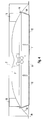
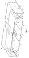
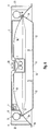
- Fig. 3 and Fig. 4 show a second embodiment of the present invention.
- the same reference numerals designate identical elements.
- the lamp operating device 7 is no longer located above the light sources 1, but rather elongated receiving spaces 18 are provided for a lamp operating device 7 at the two opposite ends of the light chamber. In this case, it is also necessary to provide the recesses with a corresponding cover (not shown) in order to close the reflector surface.
- cooling fins 6 are further designed significantly larger. This allows effective and good dissipation of the heat generated by the lamp operating devices 7.
- a third embodiment of the luminaire according to the invention is finally in the Fig. 5 and 6 shown.
- the reflector unit 2 is designed such that it picks up various components of the luminaire. These include the batteries 9, 19, the lamp operating device and leveling elements, are provided for the corresponding projections 4.
- the aluminum die cast part, which forms the reflector unit 2 in this exemplary embodiment is configured in such a way that it reproduces the shape of a luminaire trough.
- the bottom 3, 3a, 3b, 3c of the reflector unit 2 is designed as a reflective surface.
- a cover 19 covers the lamp operating device 7 and mounting elements 20.
- the underside of the cover 19 is designed as a reflector surface 3c. Outwardly, now join the reflector surfaces 3, 3a and 3b.
- the cover is much larger here. This is due only to design specifications, since the lamp operating device 7 is no longer centrally located in the lamp.
- the side walls 21, 22, 23 of the reflector unit 2 shown are also larger in this embodiment and they form the shape of a light well after. Their main task, however, continues to be the formation of recesses and formations 4 for receiving or holding functional elements of the luminaire.
- the decisive advantage in turn is that the underside of the reflector unit 2 is designed as a reflector surface 3, 3a, 3b, 3c.
- the underside 3c of the cover 19 and the underside 3, 3a, 3b of the reflector unit has been designed to be reflective.
- This also includes the outer part 3a, 3b of the reflector unit 2, which is not covered by the light exit element 10.
- the luminaire according to the invention thus produces a light image in which no contours of the luminaire can be seen, and which thus has a very even and pleasant effect on the viewer.
Landscapes
- Engineering & Computer Science (AREA)
- General Engineering & Computer Science (AREA)
- Power Engineering (AREA)
- Non-Portable Lighting Devices Or Systems Thereof (AREA)
- Fastening Of Light Sources Or Lamp Holders (AREA)
- Arrangement Of Elements, Cooling, Sealing, Or The Like Of Lighting Devices (AREA)
Abstract
Description
- Gegenstand der vorliegenden Erfindung ist eine Leuchte, welche einen Aufnahmeraum zur Aufnahme mindestens einer länglichen Lichtquelle und eine Reflektoreinheit mit mindestens einer - von dem zu beleuchtenden Bereich aus gesehen - neben der Lichtquelle angeordneten Reflektorfläche aufweist.
- Leuchten nach dem Oberbegriff des Anspruchs 1 sind beispielsweise aus der
DE 100 06 410 A1 der Anmelderin bekannt. Eine solche aus dem Stand der Technik bekannte Leuchte ist inFig. 7 dargestellt. Dabei ist unter einer länglichen Lichtquelle 101 ein Lichtbeeinflussungselement 110 in Form eines Rasterelements angeordnet. Ferner ist neben der Lichtquelle 101 ein weiteres Lichtbeeinflussungselement 111 in Form eines teillichtdurchlässigen Diffusors angeordnet. Oberhalb des Diffusors 111 weist die Leuchte eine Reflektoreinheit 102 auf. Diese Leuchte verfügt neben der Reflektoreinheit 102 über eine Gehäuseeinheit 120. Die Reflektoreinheit 102 wird an der Gehäuseeinheit montiert. Im Zuge dieser Montage ist es unvermeidlich, dass es an den Randbereichen der Reflektoreinheit 102 Überschneidungen mit der Gehäuseeinheit 120 gibt, so dass die Gehäuseeinheit 120 für störende Einflüsse auf das Lichtbild der Leuchte sorgt. Außerdem wird das Gewicht der Leuchte durch die Gehäuseeinheit 120 erhöht. - Eine weitere Leuchte gemäß dem Oberbegriff des vorliegenden Anspruchs 1 wird in der
DE 10 2006 026 207 A1 der Anmelderin offenbart. Bei dieser Leuchte ist ein einziges Lichtaustrittselement unterhalb der Lichtquelle und dem Reflektor angeordnet. Dieses Lichtaustrittselement weist einen ersten, im Wesentlichen vor der Lichtquelle befindlichen Abstrahlbereich und einen zweiten, vom ersten Bereich getrennten Abstrahlbereich auf, wobei der erste und der zweite Abstrahlbereich eine unterschiedliche Lichtabstrahlcharakteristik aufweisen. - Der Hauptanteil des Lichts wird hierbei über den ersten Abstrahlbereich abgegeben, wobei das Licht durch ein Rasterelement entblendet (längs und quer) werden kann. Der zweite Abstrahlbereich liefert dezenteres Licht, das das Licht des ersten Abstrahlbereichs untermalt und ein angenehmes optisches Bild erzeugt.
- Die in der
DE 10 2006 026 207 A1 beschriebene Leucht weist darüber hinaus eine Gehäuseeinheit auf, an der sämtliche Elemente wie Reflektor und Lichtaustrittselement befestigt sind. - Aufgabe der vorliegenden Erfindung ist es nunmehr, das in den beiden oben genannten Schriften erläuterte Leuchtenkonzept weiterzuentwickeln. Dabei wird insbesondere auf Gewichtsreduzierung sowie eine Verbesserung des Lichtbildes geachtet.
- Diese Aufgabe wird durch die in dem unabhängigen Anspruch 1 angegebene Erfindung gelöst. Vorteilhafte Weiterbildungen der vorliegenden Erfindung sind Gegenstand der Unteransprüche.
- Die erfindungsgemäße Leuchte weist einen Aufnahmeraum zur Aufnahme mindestens einer länglichen Lichtquelle und eine Reflektoreinheit mit mindestens einer - von dem zu beleuchtenden Bereich aus gesehen - neben der Lichtquelle angeordneten Reflektorfläche auf, wobei die Reflektoreinheit selbsttragend ausgebildet ist und Anformungen und/oder Ausnehmungen zur Aufnahme bzw. Halterung von Funktionselementen der Leuchte aufweist. Bei diesen Funktionselementen handelt es sich beispielsweise um Lampenfassungen, Lampenhalter, Betriebsgeräte für Lampen, Nivellierungs- und/oder Montageelemente.
- Durch die Ausgestaltung der Reflektoreinheit als selbsttragendes Element kommt es an den Randbereichen des Reflektors nicht mehr zu Störungen des Lichtbildes der Leuchte, da hier keine Verbindungselemente zu einer Gehäuseeinheit verwendet werden müssen. Die Reflektoreinheit ist nunmehr im Gegensatz zu den bisher bekannten Leuchten so stabil konstruiert, dass an ihr Befestigungselemente für die Leuchte angebracht werden können, mit denen die Leuchte an einer Wand oder Decke befestigt wird.
- Vorzugsweise wird die Reflektoreinheit aus Aluminium mittels Druckguss hergestellt und die Reflektorfläche wird anschließend durch Bedampfen oder Lackieren aufgebracht.
- In einem bevorzugten Ausführungsbeispiel sind rückseitig an der Reflektoreinheit Kühlrippen angeformt. Diese Kühlrippen ermöglichen eine effektive Abführung der von den Lampenbetriebsgeräten und den Lichtquellen erzeugten Wärme.
- Ferner können an der Reflektoreinheit Bohrungen zur Durchführung eines Werkzeugs zum Ausschwenken der Nivellierungseinheit oder zu Montagearbeiten vorgesehen sein.
- Ein Lampenbetriebsgerät kann entweder oberhalb der Lichtquelle angeordnet sein, wobei die Reflektoreinheit an der entsprechenden Stelle eine rechteckförmige Ausnehmung bildet, oder das Lampenbetriebsgeräte ist an einem oder beiden Enden des Aufnahmeraums angeordnet und die Reflektoreinheit bildet an den entsprechenden Stellen Ausnehmungen.
- Vorzugsweise ist der Aufnahmeraum durch eine Lichtaustrittsöffnung begrenzt, welche durch ein Lichtaustrittselement abgeschlossen ist.
- In diesem Fall kann die Reflektoreinheit eine umlaufende Ausnehmung oder Nut zur Verrastung mit dem Lichtaustrittselement aufweisen und die Randbereiche des Lichtaustrittselements sind nach oben geklappt bzw. abgewinkelt ausgebildet, wobei der erste hochgeklappte bzw. abgewinkelte Randbereich des Lichtaustrittselements mit dem übrigen Lichtaustrittselement einen derartigen stumpfen Winkel einschließt, so dass der Endbereich des Lichtaustrittselements senkrecht zu dem Abstrahlbereich steht.
- Vorzugsweise besteht das Lichtaustrittselement aus mehreren Teilelementen, wobei ein erstes Teilelement im Wesentlichen in einem ersten Abstrahlbereich vor der Lichtquelle angeordnet und ein zweites Teilelement im Wesentlichen seitlich von der Lichtquelle und vor der Reflektorfläche in einem zweiten Abstrahlbereich angeordnet ist und eine andere Lichtabstrahlcharakteristik aufweist als das erste Lichtaustrittselement. Ferner können das erste und/oder das zweite Teilelement in Lichtabstrahlrichtung verstellbar ausgestaltet sein.
- Im zweiten Abstrahlbereich, neben der Lampe und vor der Reflektorfläche, kann ein zumindest teillichtdurchlässiger Diffusor angeordnet sein und im ersten Lichtabstrahlbereich vor der Lampe kann ein Lichtverteilelement angeordnet sein, wobei es sich vorzugsweise um ein Rasterelement oder ein Lochblech handelt.
- Im Folgenden soll die erfindungsgemäße Leuchte anhand der beigefügten Zeichnungen näher erläutert werden. Es zeigen:
- Fig. 1
- ein erstes Ausführungsbeispiel einer erfindungsgemäßen Leuchte in einer perspektivischen Ansicht;
- Fig. 2
- einen Querschnitt durch die in
Fig. 1 dargestellte Leuchte; - Fig. 3
- ein zweites Ausführungsbeispiel einer erfindungsgemäßen Leuchte in einer perspektivischen Ansicht;
- Fig. 4
- einen Querschnitt durch die in
Fig. 3 dargestellte Leuchte; - Fig. 5
- ein drittes Ausführungsbeispiel einer erfindungsgemäßen Leuchte in einer perspektivischen Ansicht;
- Fig. 6
- einen Querschnitt durch die in
Fig. 5 dargestellte Leuchte; und - Fig. 7
- eine aus dem Stand der Technik bekannte Leuchte.
-
Fig. 1 undFig. 2 zeigen ein erstes Ausführungsbeispiel der erfindungsgemäßen Leuchte.Fig. 1 ist eine perspektivische Ansicht dieser Leuchte undFig. 2 zeigt einen Querschnitt durch die Leuchte. - Die in diesen Figuren dargestellte Leuchte weist vier Leuchtstoffröhren 1 als Lichtquellen auf. Es ist im Rahmen der vorliegenden Erfindung allerdings auch möglich, lediglich eine einzige Leuchtstoffröhre 1 oder eine andere Anzahl von Leuchtstoffröhren 1 zu verwenden. Auch die Verwendung von vollkommen anderen Lichtquellen, wie etwa Leuchtdioden, ist denkbar.
- Oberhalb der Leuchtstoffröhren 1 ist eine Reflektoreinheit 2 angeordnet, welche an der Unterseite eine Reflektorfläche 3 aufweist. Die Reflektoreinheit 2 wird aus Aluminium mittels Druckguss hergestellt und die Reflektorfläche 3 anschließend durch Bedampfen oder Lackieren aufgebracht.
- Erfindungsgemäß ist die Reflektoreinheit 2 selbsttragend ausgestaltet. Dementsprechend muss die Reflektoreinheit 2 nicht mit einer zusätzlichen Gehäuseeinheit verbunden werden, welche die Montage und die Stabilität der Leuchte gewährleisten würde. Vielmehr ist die Reflektoreinheit 2 leicht gebogen ausgestaltet. Diese Formgebung erzeugt eine Spannung, die dafür sorgt, dass die erfindungsgemäße Anordnung stabilisiert wird.
- Ferner weist die Reflektoreinheit 2 Ausnehmungen und/oder Anformungen auf,
welche die Aufnahme oder Halterung von Funktionselementen der Leuchte ermöglichen. Bei einem solchen Funktionselement handelt es sich beispielsweise um ein Nivellierungselement. Das Bezugszeichen 4 bezeichnet eine Anformung für ein solches Nivellierungselement. - Ein wesentlicher Vorteil der erfindungsgemäßen Leuchte besteht darin, dass die Anformungen 4 für die Nivellierungselemente in die Reflektoreinheit 2 integriert sind. Dadurch kann auf eine Gehäuseeinheit verzichtet werden.
- Gegenüber den aus dem Stand der Technik bekannten Leuchten bietet diese konstruktionsweise den Vorteil, dass Gewicht eingespart werden kann. Eine gewichtsreduzierte Lampe ist einfacher zu befestigen und zeichnet sich darüber hinaus auch durch geringere Herstellungskosten aus.
- Der Einsatz von Nivellierungselementen ist besonders beim Einbau der Leuchte in eine abgehängte Decke erforderlich. Die Nivellierungselemente ermöglichen hierbei, die Leuchte an die Dicke der abgehängten Decke anzupassen und sorgen auf diese Weise für eine stabile Befestigung. Verschiedene Ausgestaltungen von Nivellierungselementen sind im Stand der Technik bekannt und sind nicht Gegenstand der vorliegenden Erfindung.
- Ferner sind in der Reflektoreinheit 2 Bohrungen 5 vorgesehen. Ein Werkzeug, beispielsweise ein Schraubenzieher, kann durch eine solche Bohrung 5 hindurchgeführt werden. Mit Hilfe dieses Werkzeugs könnte ferner beispielsweise ein Nivellierungselement arretiert werden. Ist die erfindungsgemäße Leuchte in eine abhängte Decke eingelassen, so kann ein Nivellierungselement ausgeschwenkt werden, indem es über ein durch die Bohrung 5 eingeführtes Werkzeug betätigt wird. Auch im Hinblick auf Montagezwecke ist es sinnvoll, die Reflektoreinheit 2 mit entsprechenden Bohrungen 5 auszustatten.
- Des Weiteren verbessert sich durch die erfindungsgemäße Ausgestaltung der Reflektorfläche auch das Lichtbild der Leuchte. Bei der im Stand der Technik bekannten Leuchte, die auch in
Fig. 7 im Querschnitt, zu sehen ist, ist im Lichtbild stets der Randbereich zwischen Reflektorfläche und Gehäuseeinheit erkennbar. Da bei der erfindungsgemäßen Reflektoreinheit 2 die Unterseite als Reflektorfläche 3 ausgestaltet ist, ist ein solcher Übergang im Lichtbild nicht mehr erkennbar. - Eine Verbesserung des Lichtbilds der Leuchte wird insbesondere dadurch erzielt, dass auch die mit den Bezugszeichen 3a und 3b bezeichneten Flächen der Reflektoreinheit 2 als Reflektorflächen ausgestaltet sind. Dabei handelt es sich um Flächen die nicht von einem unter der Reflektoreinheit 2 angeordneten Lichtaustrittselement 10 bedeckt werden. Die genaue Ausgestaltung dieses Lichtaustrittselements 10 wird weiter unten diskutiert.
- Die Fläche 3a ergibt sich als Verlängerung der Reflektorfläche 3. Die Fläche 3b ist gegenüber den Reflektorflächen 3 und 3a abgewinkelt. Da auch die Flächen 3a und 3b reflektierend ausgestaltet sind, gibt es an den Rändern des Lichtbilds der erfindungsgemäßen Leuchte keinerlei Störeffekte, die beispielsweise durch ein nichtreflektierendes Gehäuse bei anderen im Stand der Technik bekannten Leuchten entstehen.
- An der Oberseite der Reflektoreinheit 2 sind ferner Kühlrippen 6 ausgebildet, mit deren Hilfe die von den Lichtquellen 1 und dem Lampenbetriebsgerät erzeugt Wärme aus dem Inneren der Leuchte abgeführt werden kann. Dieses Konzept ermöglicht auch den effektiven Einsatz von Leuchtdioden als Lichtquellen. Leuchtdioden benötigen ein effektives System zur Abfuhr der Wärme, da sonst der Halbleiter zerstört wird.
- Das Lampenbetriebsgerät 7 ist ebenfalls in der Reflektoreinheit 2 angeordnet. Zu diesem Zweck weist die Reflektoreinheit 2 eine entsprechende Ausnehmung auf. Im dargestellten Beispiel ist das Lampenbetriebsgerät 7 unmittelbar über den Leuchtstoffröhren 1 angeordnet. Die Reflektoreinheit 2 verfügt dementsprechend über eine rechteckförmige Ausnehmung oberhalb der Lichtquellen 1.
- Die für das Lampenbetriebsgerät 7 vorgesehene Ausnehmung wird von einer Abdeckung 19 verdeckt. Die Unterseite dieser Abdeckung 19 ist als Reflektorfläche 3c ausgestaltet. Somit ist die gesamte Unterseite 3, 3a, 3b, 3c der Reflektoreinheit 2 als reflektierende Fläche ausgestaltet. Dementsprechend sind im Lichtbild der Leuchte keinerlei Konturen der Leuchte mehr erkennbar.
- In dem in
Fig. 1 undFig. 2 gezeigten Ausführungsbeispiel ist die Abdeckung 19 mittels eines Klemmverschlusses an der Reflektoreinheit 2 befestigt. Im Rahmen der vorliegenden Erfindung ist jedoch auch eine vollkommen andere Befestigungsweise denkbar, beispielsweise durch eine Steck- oder eine Schraubverbindung. - Darüber hinaus weist die Reflektoreinheit 2 Mittel 8 zur Aufnahme bzw. Halterung eines Akkus 9 auf. Dieser kann beispielsweise in einem Notfall die Energieversorgung der Leuchte gewährleisten. Die Mittel 8 zur Aufnahme des Akkus 9 sind an der Oberseite der Leuchte angeordnet, so dass sie das Lichtbild der Leuchte nicht beeinflussen.
- An der Unterseite der Leuchte befindet sich das bereits oben erwähnte Lichtaustrittelement 10, welches in einen mittleren Bereich 11 und zwei äußere Bereiche 12 eingeteilt ist. Vorzugsweise weist der mittlere Bereich 11 eine andere Lichtabstrahlcharakteristik auf als die äußeren Bereiche 12 auf, wie dies z.B. aus der
DE 10 2006 026 207 A1 bekannt ist. - Der mittlere Bereich 11 des Lichtaustrittselements 10 kann beispielsweise als Rasterelement oder als Lochblech ausgestaltet werden. Die Verwendung von derartigen Rasterelementen oder Lochblechen ist beispielsweise bei Leuchten in Büros mit mehreren Bildschirmarbeitsplätzen von Vorteil, da das nach unten abgestrahlte Licht bis zu einem gewissen Grad querentblendet ist und daher auf den Bildschirmen keine Reflexionen verursachen kann.
- Vorzugsweise ist der äußere Bereich 12 derart ausgestaltet, dass hier dezentes Licht emittiert wird, welches das vom inneren Bereich 11 emittierte Licht untermalt und ein insgesamt angenehmeres Lichtbild erzeugt. Zu diesem Zweck kann der äußere Bereich 12 des Lichtaustrittselements 10 als zumindest teillichtdurchlässiger Diffusor ausgestaltet werden.
- Bei den im Stand der Technik bekannten Leuchten wird das Lichtaustrittselement 10 üblicherweise an einer Gehäuseeinheit befestigt. Da bei der erfindungsgemäßen Leuchte auf eine solche Gehäuseeinheit verzichtet wird, um die oben genannten Vorteile zu erzielen, muss nunmehr die Reflektoreinheit 2 derart ausgestaltet werden, dass das Lichtaustrittselement 10 an der Reflektoreinheit 2 befestigt werden kann. Zu diesem Zweck weist die Reflektoreinheit 2 eine umlaufende Ausnehmung oder Nut 13 zur Verrastung mit dem Lichtaustrittselement 10 auf.
- Als besonders vorteilhaft hat sich die in
Fig. 1 undFig. 2 gezeigte Ausgestaltung der Nut 13 und des Lichtaustrittselements 10 erwiesen. Hierbei ist der Bereich 14 des Lichtaustrittselements 10, welcher sich an den äußeren Bereich 12 anschließt um einen Winkel 15 gegenüber dem äußeren Bereich abgewinkelt. Dieser Winkel 15 ist vorzugsweise stumpf. Ferner ist der Endbereich 16 des Lichtaustrittselements, der im Fall einer Verrastung in die Nut 13 eingreift, wiederum in einem Winkel 17 gegenüber dem Abschnitt 14 angewinkelt. Der Winkel 17 wird vorzugsweise ebenfalls stumpf gewählt. - Die Bereiche 14 und 16 weisen vorzugsweise die gleiche Lichtabstrahlcharakteristik auf wie der zweite Abstrahlbereich 12. In dem vorliegenden Ausführungsbeispiel werden sie daher ebenfalls als zumindest teillichtdurchlässiger Diffusor ausgestaltet.
- Durch eine passende Wahl der Winkel 15 und 17 wird erreicht, dass der Endbereich 16 senkrecht zu dem ersten und zweiten Abstrahlbereich 11, 12 des Lichtaustrittselements 10 steht. In diesem Fall kann das Lichtaustrittselement 10 durch eine einfache vertikale Bewegung in die Nut 13 eingerastet werden. Durch ein Ziehen des eingerasteten Lichtaustrittselements 10 nach unten kann dieses wiederum aus der Nut 13 gelöst werden.
- Falls die Randbereiche 14, 16 des Lichtaustrittselements 10 nicht nach oben abgewinkelt wären und das Lichtaustrittselement 10 flach ausgestaltet wäre, so müsste die Nut 13 an den Seiten der Reflektoreinheit 2 vorgesehen werden. Dieses würde zum einen die Leuchte unnötig verbreitern und zum anderen wäre es nicht mehr möglich, das Lichtaustrittselement 10 ohne den Einsatz von Werkzeug in die Nut 13 ein- und auszurasten.
- Ferner hat es sich als sinnvoll herausgestellt, das Lichtaustrittselement 10 um die zwei stumpfen Winkel 15, 17 abzuwinkeln, anstatt es lediglich an einer einzigen Stelle um einen rechten Winkel abzuknicken. Die erfindungsgemäße Form bietet eine größere Stabilität und sofern der Bereich 14 des Lichtaustrittselements ebenfalls als zumindest teillichtdurchlässiger Diffusor ausgestaltet ist, wird durch die Abwinklung um einen stumpfen Winkel 15 das Lichtbild der Leuchte deutlich weniger gestört als dieses bei einer Abwinkelung um einen rechten Winkel der Fall wäre.
-
Fig. 3 undFig. 4 zeigen ein zweites Ausführungsbeispiel der vorliegenden Erfindung. Gleiche Bezugszeichen bezeichnen hierbei baugleiche Elemente. - Bei der in
Fig. 3 undFig. 4 gezeigten Leuchte ist das Lampenbetriebsgerät 7 nicht mehr oberhalb der Lichtquellen 1 angeordnet, sondern es sind vielmehr längliche Aufnahmeräume 18 für ein Lampenbetriebsgerät 7 an den beiden gegenüberliegenden Enden der Lichtkammer vorgesehen. Hierbei ist es ebenfalls erforderlich, die Ausnehmungen mit einer entsprechenden - nicht dargestellten - Abdeckung zu versehen, um die Reflektorfläche zu schließen. - Bei dem zweiten Ausführungsbeispiel sind ferner die Kühlrippen 6 deutlich größer ausgestaltet. Dieses ermöglicht eine effektive und gute Abführung der von den Lampenbetriebsgeräten 7 erzeugten Wärme.
- Ein drittes Ausführungsbeispiel der erfindungsgemäßen Leuchte ist schließlich in den
Fig. 5 und6 dargestellt. Auch hier ist die Reflektoreinheit 2 derart ausgestaltet, dass sie verschiedene Komponenten der Leuchte aufnimmt. Hierzu gehören die Akkus 9, 19, das Lampenbetriebsgerät und Nivellierungselemente, für die entsprechende Anformungen 4 vorgesehen sind. - Das Aluminium-Druckgußteil, welches die Reflektoreinheit 2 bildet, ist in diesem Ausführungsbeispiel derart ausgestaltet, dass es die Form einer Leuchtenwanne nachbildet. Wiederum ist die Unterseite 3, 3a, 3b, 3c der Reflektoreinheit 2 als reflektierende Fläche ausgestaltet.
- Eine Abdeckung 19 bedeckt das Lampenbetriebsgerät 7 sowie Montageelemente 20. Die Unterseite der Abdeckung 19 ist als Reflektorfläche 3c ausgestaltet. Nach außen hin, schließen sich nunmehr die Reflektorflächen 3, 3a und 3b an.
- Im Vergleich zu dem in
Fig. 1 undFig. 2 gezeigten Ausführungsbeispiel ist die Abdeckung hier wesentlich größer. Dieses ist auf lediglich konstruktive Vorgaben zurückzuführen, da das Lampenbetriebsgerät 7 nun nicht mehr mittig in der Leuchte angeordnet ist. - Die Seitenwände 21, 22, 23 der gezeigten Reflektoreinheit 2 sind in diesem Ausführungsbeispiel ebenfalls größer und sie bilden die Form einer Leuchtenwanne nach. Ihre Hauptaufgabe besteht allerdings weiterhin in der Ausbildung von Ausnehmungen und Anformungen 4 zur Aufnahme bzw. Halterung von Funktionselementen der Leuchte.
- Bei dem dritten Ausführungsbeispiel besteht gegenüber dem bekannten Stand der Technik wiederum der entscheidende Vorteil darin, dass die Unterseite der Reflektoreinheit 2 als Reflektorfläche 3, 3a, 3b, 3c ausgestaltet ist. Zu diesem Zweck wurde die Unterseite 3c der Abdeckung 19 sowie die Unterseite 3, 3a, 3b der Reflektoreinheit reflektierend ausgestaltet. Dieses umfasst auch den äußeren Teil 3a, 3b der Reflektoreinheit 2, welcher nicht von dem Lichtaustrittselement 10 bedeckt ist.
- Insgesamt erzeugt die erfindungsgemäße Leuchte somit ein Lichtbild, in dem keinerlei Konturen der Leuchte erkennbar sind, und das somit für den Betrachter sehr gleichmäßig und angenehm wirkt.
Claims (17)
- Leuchte aufweisend einen Aufnahmeraum zur Aufnahme mindestens einer länglichen Lichtquelle (1) und eine Reflektoreinheit (2) mit mindestens einer - von dem zu beleuchtenden Bereich aus gesehen - neben der Lichtquelle (1) angeordneten Reflektorfläche (3, 3a, 3b, 3c),
dadurch gekennzeichnet,
dass die Reflektoreinheit (2) selbsttragend ausgebildet ist und Anformungen (4) und/oder Ausnehmungen zur Aufnahme bzw. Halterung von Funktionselementen der Leuchte wie beispielsweise Lampenfassungen, Lampenhalter, Betriebsgeräte (7) für Lampen, Nivellierungs- und/oder Montageelemente aufweist. - Leuchte nach einem der vorherigen Ansprüche,
dadurch gekennzeichnet,
dass die Reflektoreinheit (2) aus Aluminium mittels Druckguss hergestellt ist und die Reflektorfläche (3, 3a, 3b, 3c) durch Bedampfen oder Lackieren aufgebracht ist. - Leuchte nach einem der vorherigen Ansprüche,
dadurch gekennzeichnet,
dass rückseitig an der Reflektoreinheit (2) Kühlrippen (6) angeformt sind. - Leuchte nach einem der vorherigen Ansprüche,
dadurch gekennzeichnet,
dass an der Reflektoreinheit (2) Bohrungen (5) zur Durchführung eines Werkzeugs zum Ausschwenken der Nivellierungseinheit oder zu Montagearbeiten vorgesehen sind. - Leuchte nach einem der vorherigen Ansprüche,
dadurch gekennzeichnet,
dass ein Lampenbetriebsgerät (7) oberhalb der Lichtquelle (1) angeordnet ist und die Reflektoreinheit (2) an der entsprechenden Stelle eine rechteckförmige Ausnehmung bildet. - Leuchte nach einem der Ansprüche 1 bis 5,
dadurch gekennzeichnet,
dass die Lampenbetriebsgeräte (7) an einem oder beiden Enden des Aufnahmeraums angeordnet sind und die Reflektoreinheit (2) an der entsprechenden Stelle Ausnehmung bildet. - Leuchte nach einem der vorherigen Ansprüche,
dadurch gekennzeichnet,
dass der Aufnahmeraum eine Lichtaustrittsöffnung begrenzt, welche durch ein Lichtaustrittselement (10) abgeschlossen ist. - Leuchte nach Anspruch 7,
dadurch gekennzeichnet,
dass die Reflektoreinheit (2) eine umlaufende Ausnehmung oder Nut (13) zur Verrastung mit dem Lichtaustrittselement (10) aufweist. - Leuchte nach Anspruch 8,
dadurch gekennzeichnet,
dass die Randbereiche (14, 16) des Lichtaustrittselements (10) nach oben geklappt sind. - Leuchte nach Anspruch 9,
dadurch gekennzeichnet,
dass der hochgeklappte Randbereich (14) des Lichtaustrittselements (10) mit dem übrigen Lichtaustrittselement (12) einen stumpfen Winkel (15)
einschließt. - Leuchte nach einem der Ansprüche 8 oder 9,
dadurch gekennzeichnet,
dass der Endbereich (16) des Lichtaustrittselements (10) senkrecht zu dem Abstrahlbereich (11, 12) steht. - Leuchte nach einem der Ansprüche 7 bis 11,
dadurch gekennzeichnet,
dass das Lichtaustrittselement (10) aus mehreren Teilelementen besteht, wobei ein erstes Teilelement im Wesentlichen in einem ersten Abstrahlbereich (11) vor der Lichtquelle (1) angeordnet und ein zweites Teilelement im Wesentlichen seitlich von der Lichtquelle (1) und vor der Reflektorfläche (3, 3a, 3b, 3c) in einem zweiten Abstrahlbereich (11) angeordnet ist und eine andere Lichtabstrahlcharakteristik aufweist als das erste Lichtaustrittselement. - Leuchte nach Anspruch 12,
dadurch gekennzeichnet,
dass das erste und/oder das zweite Teilelement in Lichtabstrahlrichtung verstellbar sind. - Leuchte nach Anspruch 12 oder 13,
dadurch gekennzeichnet,
dass im zweiten Abstrahlbereich (12), neben der Lichtquelle (1) und vor der Reflektorfläche (3, 3a, 3b, 3c), ein zumindest teillichtdurchlässiger Diffusor angeordnet ist. - Leuchte nach einem der Ansprüche 12 bis 14,
dadurch gekennzeichnet,
dass im ersten Lichtabstrahlbereich (11) vor der Lichtquelle (1) ein Lichtverteilelement angeordnet ist. - Leuchte nach Anspruch 15,
dadurch gekennzeichnet,
dass es sich bei dem Lichtverteilelement um ein Rasterelement handelt. - Leuchte nach Anspruch 15,
dadurch gekennzeichnet,
dass es sich bei dem Lichtverteilelement um ein Lochblech handelt.
Applications Claiming Priority (1)
| Application Number | Priority Date | Filing Date | Title |
|---|---|---|---|
| DE102008006576A DE102008006576A1 (de) | 2008-01-29 | 2008-01-29 | Leuchte mit selbsttragender Reflektoreinheit |
Publications (2)
| Publication Number | Publication Date |
|---|---|
| EP2085684A1 true EP2085684A1 (de) | 2009-08-05 |
| EP2085684B1 EP2085684B1 (de) | 2012-01-25 |
Family
ID=40578846
Family Applications (1)
| Application Number | Title | Priority Date | Filing Date |
|---|---|---|---|
| EP09151603A Not-in-force EP2085684B1 (de) | 2008-01-29 | 2009-01-29 | Leuchte mit selbsttragender Reflektoreinheit |
Country Status (3)
| Country | Link |
|---|---|
| EP (1) | EP2085684B1 (de) |
| AT (1) | ATE543044T1 (de) |
| DE (1) | DE102008006576A1 (de) |
Cited By (1)
| Publication number | Priority date | Publication date | Assignee | Title |
|---|---|---|---|---|
| WO2017121121A1 (zh) * | 2016-01-11 | 2017-07-20 | 深圳市桑达实业股份有限公司 | 路灯外壳及路灯 |
Families Citing this family (1)
| Publication number | Priority date | Publication date | Assignee | Title |
|---|---|---|---|---|
| DE102010037630A1 (de) * | 2010-09-17 | 2012-03-22 | Manfred Grimm | Leuchte |
Citations (5)
| Publication number | Priority date | Publication date | Assignee | Title |
|---|---|---|---|---|
| GB753477A (en) * | 1953-05-07 | 1956-07-25 | New Era Ind Tottenham Ltd | Improvements in reflectors for fluorescent lighting |
| US3085152A (en) * | 1958-09-02 | 1963-04-09 | Robert A D Schwartz | Lighting fixture with ceiling panel supporting element |
| GB2301176A (en) * | 1995-05-20 | 1996-11-27 | Add Reflectors Ltd | Luminaire |
| DE10006410A1 (de) | 2000-02-14 | 2001-08-16 | Zumtobel Staff Gmbh | Leuchte |
| DE102006026207A1 (de) | 2006-05-30 | 2007-12-06 | Siemens Ag | Bauteil für eine thermische Beanspruchung, insbesondere Turbinenschaufel |
Family Cites Families (2)
| Publication number | Priority date | Publication date | Assignee | Title |
|---|---|---|---|---|
| DE2319316C3 (de) * | 1973-04-17 | 1985-06-20 | Händler, Paul, 8400 Regensburg | Leuchte mit breitem, gewölbtem Blechreflektor niedriger Bauhöhe |
| DE4210444A1 (de) * | 1992-03-30 | 1993-10-07 | Hartmut S Engel | Strahler mit gestufter Reflektorfläche |
-
2008
- 2008-01-29 DE DE102008006576A patent/DE102008006576A1/de not_active Withdrawn
-
2009
- 2009-01-29 EP EP09151603A patent/EP2085684B1/de not_active Not-in-force
- 2009-01-29 AT AT09151603T patent/ATE543044T1/de active
Patent Citations (5)
| Publication number | Priority date | Publication date | Assignee | Title |
|---|---|---|---|---|
| GB753477A (en) * | 1953-05-07 | 1956-07-25 | New Era Ind Tottenham Ltd | Improvements in reflectors for fluorescent lighting |
| US3085152A (en) * | 1958-09-02 | 1963-04-09 | Robert A D Schwartz | Lighting fixture with ceiling panel supporting element |
| GB2301176A (en) * | 1995-05-20 | 1996-11-27 | Add Reflectors Ltd | Luminaire |
| DE10006410A1 (de) | 2000-02-14 | 2001-08-16 | Zumtobel Staff Gmbh | Leuchte |
| DE102006026207A1 (de) | 2006-05-30 | 2007-12-06 | Siemens Ag | Bauteil für eine thermische Beanspruchung, insbesondere Turbinenschaufel |
Cited By (1)
| Publication number | Priority date | Publication date | Assignee | Title |
|---|---|---|---|---|
| WO2017121121A1 (zh) * | 2016-01-11 | 2017-07-20 | 深圳市桑达实业股份有限公司 | 路灯外壳及路灯 |
Also Published As
| Publication number | Publication date |
|---|---|
| ATE543044T1 (de) | 2012-02-15 |
| DE102008006576A1 (de) | 2009-07-30 |
| EP2085684B1 (de) | 2012-01-25 |
Similar Documents
| Publication | Publication Date | Title |
|---|---|---|
| EP2020562A1 (de) | Wandleuchte | |
| EP2924333A1 (de) | Modulare Leuchte | |
| EP2886946A1 (de) | Halter für eine Betriebskomponente einer Leuchte | |
| EP2650594B1 (de) | Leuchte mit Lampe | |
| EP3414487B1 (de) | Lichtbandsystem mit länglicher tragschiene | |
| EP2085684B1 (de) | Leuchte mit selbsttragender Reflektoreinheit | |
| DE202012005765U1 (de) | LED-Einbauleuchte | |
| DE202017102009U1 (de) | Leuchte | |
| DE202012103474U1 (de) | LED-Leuchte | |
| DE102012206070A1 (de) | Lichtband mit Leuchte | |
| EP3426975B1 (de) | Leuchte zur gleichmässigen ausleuchtung | |
| EP2175188B1 (de) | Leuchte | |
| EP4063717A1 (de) | Leuchte mit vorderseitiger kühlfunktion | |
| EP2176583B1 (de) | Leuchte mit raster zur lichtabgabe | |
| EP3627045B1 (de) | Leuchtmitteleinsatzmodul | |
| DE202016106056U1 (de) | Linienleuchte | |
| EP1264137A1 (de) | Leuchte, insbesondere einbauleuchte | |
| EP1538394B1 (de) | Profilrahmen-Leuchte | |
| EP4477942B1 (de) | Pendelleuchte mit sicherungselement | |
| DE19833217B4 (de) | Modulleuchte | |
| EP2518388B1 (de) | Leuchte | |
| WO2002044614A1 (de) | Leuchte mit einer abdeckscheibe | |
| DE202023102977U1 (de) | Stehleuchte mit einstellbarem Leuchtenkopf mit Anschlag | |
| EP1132681B1 (de) | Tragschienensystem | |
| EP4296562A1 (de) | Längliche leuchteneinheit sowie damit ausgestattetes deckensystem |
Legal Events
| Date | Code | Title | Description |
|---|---|---|---|
| PUAI | Public reference made under article 153(3) epc to a published international application that has entered the european phase |
Free format text: ORIGINAL CODE: 0009012 |
|
| AK | Designated contracting states |
Kind code of ref document: A1 Designated state(s): AT BE BG CH CY CZ DE DK EE ES FI FR GB GR HR HU IE IS IT LI LT LU LV MC MK MT NL NO PL PT RO SE SI SK TR |
|
| AX | Request for extension of the european patent |
Extension state: AL BA RS |
|
| 17P | Request for examination filed |
Effective date: 20100205 |
|
| 17Q | First examination report despatched |
Effective date: 20100302 |
|
| AKX | Designation fees paid |
Designated state(s): AT BE BG CH CY CZ DE DK EE ES FI FR GB GR HR HU IE IS IT LI LT LU LV MC MK MT NL NO PL PT RO SE SI SK TR |
|
| GRAP | Despatch of communication of intention to grant a patent |
Free format text: ORIGINAL CODE: EPIDOSNIGR1 |
|
| GRAS | Grant fee paid |
Free format text: ORIGINAL CODE: EPIDOSNIGR3 |
|
| GRAA | (expected) grant |
Free format text: ORIGINAL CODE: 0009210 |
|
| AK | Designated contracting states |
Kind code of ref document: B1 Designated state(s): AT BE BG CH CY CZ DE DK EE ES FI FR GB GR HR HU IE IS IT LI LT LU LV MC MK MT NL NO PL PT RO SE SI SK TR |
|
| REG | Reference to a national code |
Ref country code: GB Ref legal event code: FG4D Free format text: NOT ENGLISH |
|
| REG | Reference to a national code |
Ref country code: CH Ref legal event code: EP Ref country code: CH Ref legal event code: NV Representative=s name: RIEDERER HASLER & PARTNER PATENTANWAELTE AG |
|
| REG | Reference to a national code |
Ref country code: AT Ref legal event code: REF Ref document number: 543044 Country of ref document: AT Kind code of ref document: T Effective date: 20120215 |
|
| REG | Reference to a national code |
Ref country code: IE Ref legal event code: FG4D |
|
| REG | Reference to a national code |
Ref country code: DE Ref legal event code: R096 Ref document number: 502009002540 Country of ref document: DE Effective date: 20120322 |
|
| REG | Reference to a national code |
Ref country code: NL Ref legal event code: VDEP Effective date: 20120125 |
|
| LTIE | Lt: invalidation of european patent or patent extension |
Effective date: 20120125 |
|
| BERE | Be: lapsed |
Owner name: ZUMTOBEL LIGHTING GMBH Effective date: 20120131 |
|
| PG25 | Lapsed in a contracting state [announced via postgrant information from national office to epo] |
Ref country code: NO Free format text: LAPSE BECAUSE OF FAILURE TO SUBMIT A TRANSLATION OF THE DESCRIPTION OR TO PAY THE FEE WITHIN THE PRESCRIBED TIME-LIMIT Effective date: 20120425 Ref country code: BG Free format text: LAPSE BECAUSE OF FAILURE TO SUBMIT A TRANSLATION OF THE DESCRIPTION OR TO PAY THE FEE WITHIN THE PRESCRIBED TIME-LIMIT Effective date: 20120425 Ref country code: HR Free format text: LAPSE BECAUSE OF FAILURE TO SUBMIT A TRANSLATION OF THE DESCRIPTION OR TO PAY THE FEE WITHIN THE PRESCRIBED TIME-LIMIT Effective date: 20120125 Ref country code: NL Free format text: LAPSE BECAUSE OF FAILURE TO SUBMIT A TRANSLATION OF THE DESCRIPTION OR TO PAY THE FEE WITHIN THE PRESCRIBED TIME-LIMIT Effective date: 20120125 Ref country code: LT Free format text: LAPSE BECAUSE OF FAILURE TO SUBMIT A TRANSLATION OF THE DESCRIPTION OR TO PAY THE FEE WITHIN THE PRESCRIBED TIME-LIMIT Effective date: 20120125 Ref country code: IS Free format text: LAPSE BECAUSE OF FAILURE TO SUBMIT A TRANSLATION OF THE DESCRIPTION OR TO PAY THE FEE WITHIN THE PRESCRIBED TIME-LIMIT Effective date: 20120525 |
|
| REG | Reference to a national code |
Ref country code: IE Ref legal event code: FD4D |
|
| PG25 | Lapsed in a contracting state [announced via postgrant information from national office to epo] |
Ref country code: PT Free format text: LAPSE BECAUSE OF FAILURE TO SUBMIT A TRANSLATION OF THE DESCRIPTION OR TO PAY THE FEE WITHIN THE PRESCRIBED TIME-LIMIT Effective date: 20120525 Ref country code: GR Free format text: LAPSE BECAUSE OF FAILURE TO SUBMIT A TRANSLATION OF THE DESCRIPTION OR TO PAY THE FEE WITHIN THE PRESCRIBED TIME-LIMIT Effective date: 20120426 Ref country code: LV Free format text: LAPSE BECAUSE OF FAILURE TO SUBMIT A TRANSLATION OF THE DESCRIPTION OR TO PAY THE FEE WITHIN THE PRESCRIBED TIME-LIMIT Effective date: 20120125 Ref country code: MC Free format text: LAPSE BECAUSE OF NON-PAYMENT OF DUE FEES Effective date: 20120131 Ref country code: FI Free format text: LAPSE BECAUSE OF FAILURE TO SUBMIT A TRANSLATION OF THE DESCRIPTION OR TO PAY THE FEE WITHIN THE PRESCRIBED TIME-LIMIT Effective date: 20120125 Ref country code: PL Free format text: LAPSE BECAUSE OF FAILURE TO SUBMIT A TRANSLATION OF THE DESCRIPTION OR TO PAY THE FEE WITHIN THE PRESCRIBED TIME-LIMIT Effective date: 20120125 |
|
| PG25 | Lapsed in a contracting state [announced via postgrant information from national office to epo] |
Ref country code: CY Free format text: LAPSE BECAUSE OF FAILURE TO SUBMIT A TRANSLATION OF THE DESCRIPTION OR TO PAY THE FEE WITHIN THE PRESCRIBED TIME-LIMIT Effective date: 20120125 |
|
| PG25 | Lapsed in a contracting state [announced via postgrant information from national office to epo] |
Ref country code: DK Free format text: LAPSE BECAUSE OF FAILURE TO SUBMIT A TRANSLATION OF THE DESCRIPTION OR TO PAY THE FEE WITHIN THE PRESCRIBED TIME-LIMIT Effective date: 20120125 Ref country code: SI Free format text: LAPSE BECAUSE OF FAILURE TO SUBMIT A TRANSLATION OF THE DESCRIPTION OR TO PAY THE FEE WITHIN THE PRESCRIBED TIME-LIMIT Effective date: 20120125 Ref country code: EE Free format text: LAPSE BECAUSE OF FAILURE TO SUBMIT A TRANSLATION OF THE DESCRIPTION OR TO PAY THE FEE WITHIN THE PRESCRIBED TIME-LIMIT Effective date: 20120125 Ref country code: IE Free format text: LAPSE BECAUSE OF FAILURE TO SUBMIT A TRANSLATION OF THE DESCRIPTION OR TO PAY THE FEE WITHIN THE PRESCRIBED TIME-LIMIT Effective date: 20120125 Ref country code: RO Free format text: LAPSE BECAUSE OF FAILURE TO SUBMIT A TRANSLATION OF THE DESCRIPTION OR TO PAY THE FEE WITHIN THE PRESCRIBED TIME-LIMIT Effective date: 20120125 Ref country code: CZ Free format text: LAPSE BECAUSE OF FAILURE TO SUBMIT A TRANSLATION OF THE DESCRIPTION OR TO PAY THE FEE WITHIN THE PRESCRIBED TIME-LIMIT Effective date: 20120125 Ref country code: SE Free format text: LAPSE BECAUSE OF FAILURE TO SUBMIT A TRANSLATION OF THE DESCRIPTION OR TO PAY THE FEE WITHIN THE PRESCRIBED TIME-LIMIT Effective date: 20120125 |
|
| PG25 | Lapsed in a contracting state [announced via postgrant information from national office to epo] |
Ref country code: SK Free format text: LAPSE BECAUSE OF FAILURE TO SUBMIT A TRANSLATION OF THE DESCRIPTION OR TO PAY THE FEE WITHIN THE PRESCRIBED TIME-LIMIT Effective date: 20120125 Ref country code: IT Free format text: LAPSE BECAUSE OF FAILURE TO SUBMIT A TRANSLATION OF THE DESCRIPTION OR TO PAY THE FEE WITHIN THE PRESCRIBED TIME-LIMIT Effective date: 20120125 |
|
| PLBE | No opposition filed within time limit |
Free format text: ORIGINAL CODE: 0009261 |
|
| STAA | Information on the status of an ep patent application or granted ep patent |
Free format text: STATUS: NO OPPOSITION FILED WITHIN TIME LIMIT |
|
| PG25 | Lapsed in a contracting state [announced via postgrant information from national office to epo] |
Ref country code: BE Free format text: LAPSE BECAUSE OF NON-PAYMENT OF DUE FEES Effective date: 20120131 |
|
| 26N | No opposition filed |
Effective date: 20121026 |
|
| REG | Reference to a national code |
Ref country code: FR Ref legal event code: ST Effective date: 20121207 |
|
| PG25 | Lapsed in a contracting state [announced via postgrant information from national office to epo] |
Ref country code: FR Free format text: LAPSE BECAUSE OF NON-PAYMENT OF DUE FEES Effective date: 20120326 |
|
| REG | Reference to a national code |
Ref country code: DE Ref legal event code: R097 Ref document number: 502009002540 Country of ref document: DE Effective date: 20121026 |
|
| PG25 | Lapsed in a contracting state [announced via postgrant information from national office to epo] |
Ref country code: MK Free format text: LAPSE BECAUSE OF FAILURE TO SUBMIT A TRANSLATION OF THE DESCRIPTION OR TO PAY THE FEE WITHIN THE PRESCRIBED TIME-LIMIT Effective date: 20120125 |
|
| PG25 | Lapsed in a contracting state [announced via postgrant information from national office to epo] |
Ref country code: ES Free format text: LAPSE BECAUSE OF FAILURE TO SUBMIT A TRANSLATION OF THE DESCRIPTION OR TO PAY THE FEE WITHIN THE PRESCRIBED TIME-LIMIT Effective date: 20120506 |
|
| PG25 | Lapsed in a contracting state [announced via postgrant information from national office to epo] |
Ref country code: MT Free format text: LAPSE BECAUSE OF FAILURE TO SUBMIT A TRANSLATION OF THE DESCRIPTION OR TO PAY THE FEE WITHIN THE PRESCRIBED TIME-LIMIT Effective date: 20120125 |
|
| PG25 | Lapsed in a contracting state [announced via postgrant information from national office to epo] |
Ref country code: TR Free format text: LAPSE BECAUSE OF FAILURE TO SUBMIT A TRANSLATION OF THE DESCRIPTION OR TO PAY THE FEE WITHIN THE PRESCRIBED TIME-LIMIT Effective date: 20120125 |
|
| PG25 | Lapsed in a contracting state [announced via postgrant information from national office to epo] |
Ref country code: LU Free format text: LAPSE BECAUSE OF NON-PAYMENT OF DUE FEES Effective date: 20120129 |
|
| PG25 | Lapsed in a contracting state [announced via postgrant information from national office to epo] |
Ref country code: HU Free format text: LAPSE BECAUSE OF FAILURE TO SUBMIT A TRANSLATION OF THE DESCRIPTION OR TO PAY THE FEE WITHIN THE PRESCRIBED TIME-LIMIT Effective date: 20090129 |
|
| PGFP | Annual fee paid to national office [announced via postgrant information from national office to epo] |
Ref country code: CH Payment date: 20160125 Year of fee payment: 8 |
|
| PGFP | Annual fee paid to national office [announced via postgrant information from national office to epo] |
Ref country code: AT Payment date: 20160128 Year of fee payment: 8 |
|
| REG | Reference to a national code |
Ref country code: CH Ref legal event code: PL |
|
| REG | Reference to a national code |
Ref country code: AT Ref legal event code: MM01 Ref document number: 543044 Country of ref document: AT Kind code of ref document: T Effective date: 20170129 |
|
| PG25 | Lapsed in a contracting state [announced via postgrant information from national office to epo] |
Ref country code: CH Free format text: LAPSE BECAUSE OF NON-PAYMENT OF DUE FEES Effective date: 20170131 Ref country code: AT Free format text: LAPSE BECAUSE OF NON-PAYMENT OF DUE FEES Effective date: 20170129 Ref country code: LI Free format text: LAPSE BECAUSE OF NON-PAYMENT OF DUE FEES Effective date: 20170131 |
|
| REG | Reference to a national code |
Ref country code: DE Ref legal event code: R084 Ref document number: 502009002540 Country of ref document: DE |
|
| PGFP | Annual fee paid to national office [announced via postgrant information from national office to epo] |
Ref country code: GB Payment date: 20210128 Year of fee payment: 13 Ref country code: DE Payment date: 20210129 Year of fee payment: 13 |
|
| REG | Reference to a national code |
Ref country code: DE Ref legal event code: R119 Ref document number: 502009002540 Country of ref document: DE |
|
| GBPC | Gb: european patent ceased through non-payment of renewal fee |
Effective date: 20220129 |
|
| PG25 | Lapsed in a contracting state [announced via postgrant information from national office to epo] |
Ref country code: GB Free format text: LAPSE BECAUSE OF NON-PAYMENT OF DUE FEES Effective date: 20220129 Ref country code: DE Free format text: LAPSE BECAUSE OF NON-PAYMENT OF DUE FEES Effective date: 20220802 |