EP2085267A1 - Bac de rangement pour véhicule - Google Patents
Bac de rangement pour véhicule Download PDFInfo
- Publication number
- EP2085267A1 EP2085267A1 EP09305098A EP09305098A EP2085267A1 EP 2085267 A1 EP2085267 A1 EP 2085267A1 EP 09305098 A EP09305098 A EP 09305098A EP 09305098 A EP09305098 A EP 09305098A EP 2085267 A1 EP2085267 A1 EP 2085267A1
- Authority
- EP
- European Patent Office
- Prior art keywords
- hinge member
- hinge
- tray
- vehicle
- lid
- Prior art date
- Legal status (The legal status is an assumption and is not a legal conclusion. Google has not performed a legal analysis and makes no representation as to the accuracy of the status listed.)
- Granted
Links
Images



Classifications
-
- B—PERFORMING OPERATIONS; TRANSPORTING
- B60—VEHICLES IN GENERAL
- B60R—VEHICLES, VEHICLE FITTINGS, OR VEHICLE PARTS, NOT OTHERWISE PROVIDED FOR
- B60R7/00—Stowing or holding appliances inside vehicle primarily intended for personal property smaller than suit-cases, e.g. travelling articles, or maps
- B60R7/04—Stowing or holding appliances inside vehicle primarily intended for personal property smaller than suit-cases, e.g. travelling articles, or maps in driver or passenger space, e.g. using racks
-
- B—PERFORMING OPERATIONS; TRANSPORTING
- B60—VEHICLES IN GENERAL
- B60N—SEATS SPECIALLY ADAPTED FOR VEHICLES; VEHICLE PASSENGER ACCOMMODATION NOT OTHERWISE PROVIDED FOR
- B60N2/00—Seats specially adapted for vehicles; Arrangement or mounting of seats in vehicles
- B60N2/75—Arm-rests
- B60N2/79—Adaptations for additional use of the arm-rests
- B60N2/793—Adaptations for additional use of the arm-rests for use as storage compartments
-
- B—PERFORMING OPERATIONS; TRANSPORTING
- B60—VEHICLES IN GENERAL
- B60R—VEHICLES, VEHICLE FITTINGS, OR VEHICLE PARTS, NOT OTHERWISE PROVIDED FOR
- B60R11/00—Arrangements for holding or mounting articles, not otherwise provided for
- B60R2011/0001—Arrangements for holding or mounting articles, not otherwise provided for characterised by position
- B60R2011/0003—Arrangements for holding or mounting articles, not otherwise provided for characterised by position inside the vehicle
- B60R2011/0007—Mid-console
-
- B—PERFORMING OPERATIONS; TRANSPORTING
- B60—VEHICLES IN GENERAL
- B60R—VEHICLES, VEHICLE FITTINGS, OR VEHICLE PARTS, NOT OTHERWISE PROVIDED FOR
- B60R11/00—Arrangements for holding or mounting articles, not otherwise provided for
- B60R2011/0001—Arrangements for holding or mounting articles, not otherwise provided for characterised by position
- B60R2011/0003—Arrangements for holding or mounting articles, not otherwise provided for characterised by position inside the vehicle
- B60R2011/0012—Seats or parts thereof
- B60R2011/0014—Arm-rests
-
- E—FIXED CONSTRUCTIONS
- E05—LOCKS; KEYS; WINDOW OR DOOR FITTINGS; SAFES
- E05D—HINGES OR SUSPENSION DEVICES FOR DOORS, WINDOWS OR WINGS
- E05D11/00—Additional features or accessories of hinges
- E05D11/06—Devices for limiting the opening movement of hinges
-
- E—FIXED CONSTRUCTIONS
- E05—LOCKS; KEYS; WINDOW OR DOOR FITTINGS; SAFES
- E05D—HINGES OR SUSPENSION DEVICES FOR DOORS, WINDOWS OR WINGS
- E05D7/00—Hinges or pivots of special construction
- E05D7/12—Hinges or pivots of special construction to allow easy detachment of the hinge from the wing or the frame
- E05D7/121—Hinges or pivots of special construction to allow easy detachment of the hinge from the wing or the frame specially adapted for vehicles
-
- E—FIXED CONSTRUCTIONS
- E05—LOCKS; KEYS; WINDOW OR DOOR FITTINGS; SAFES
- E05Y—INDEXING SCHEME ASSOCIATED WITH SUBCLASSES E05D AND E05F, RELATING TO CONSTRUCTION ELEMENTS, ELECTRIC CONTROL, POWER SUPPLY, POWER SIGNAL OR TRANSMISSION, USER INTERFACES, MOUNTING OR COUPLING, DETAILS, ACCESSORIES, AUXILIARY OPERATIONS NOT OTHERWISE PROVIDED FOR, APPLICATION THEREOF
- E05Y2900/00—Application of doors, windows, wings or fittings thereof
- E05Y2900/50—Application of doors, windows, wings or fittings thereof for vehicles
- E05Y2900/53—Type of wing
- E05Y2900/538—Interior lids
Definitions
- the invention relates to a storage bin to be placed in the passenger compartment of a vehicle, the tank comprising a hinge member, a plastic body and a lid, the body and the lid being pivotally connected together by the body hinge.
- Such bins can take the form of central consoles.
- a problem that is intended here to solve is to achieve a hinge system with blocks or parts that are easy to set up, effective fixation, effective once mounted in place and a cost well mastered.
- the hinge member comprises a first and a second plastic parts pivotally mounted relative to each other around a shaft, the first part being fixed to the lid insert, the second part having a plurality of projecting studs engaged in cavities of the container body to be held therein, the studs including locking lugs whose engagement, in a predetermined direction, in recessed areas formed in said cavities prevents subsequent withdrawal , complementary fixing means mounted between the body of the tray and the second part of the hinge member being adapted to fix them together, once the latches locked in said recessed areas.
- FIG. 1 On the figure 1 , is shown an example of implantation of a storage bin 1 to be disposed in the passenger compartment 3 of a vehicle 5, here an automobile.
- the container comprises a hinge member 7, a plastic body 9 and a lid 11.
- the hinge member comprises first and second plastic parts 7a, 7b pivotally mounted relative to one another about a shaft 12.
- the tray is mounted between the driver's seat 40a of the vehicle 5 and the passenger seat 40b located next to it.
- the tray thus defines the central console of this vehicle, with its lid 11 arranged at a height H adapted to serve as a bend, in the closed position, while the first part 7a of the hinge member is folded flat on the second part 7b.
- the body 9 and the lid 11 are connected together, pivotally, by the hinge member 7.
- the lid 11 comprises a rigid plastic insert 11a and a thin skin (outer) 11b appearance, typically molded flexible plastic, or leather attached to the insert.
- the first part 7a is fixed to the insert 11a, in particular by the clips 10; cf. fig.2 .
- the shaft 12 will be locally carried by this insert. Fig.4 it is seen that elsewhere, the shaft 12 is locally held in a channel 70a of the first portion 7a of the hinge member.
- the fig.7 also details the assembly with part 7b.
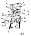
- This second part 7b also has several projecting studs 13a, 13b engaged in cavities 15a, 15b of the body 9 of the tray to be fixedly held there; cf. fig.3 especially.
- the pads 13a, 13b comprise locking lugs 17a, 17b whose engagement, in a predetermined direction E , in the recessed areas 19a, 19b formed in the cavities 15a, 15b of the tank body prevents the subsequent withdrawal; cf. especially fig.3 .
- Complementary fixing means such as 21a ( fig.5 ) are mounted between the body 9 and the second part 7b of the hinge member, to fix them together, once the lugs 17a, 17b locked in the recessed areas 19a, 19b.
- the second hinge portion 7b has, at a level above the projecting studs 13a, 13b, an internally concave shape 23 opposite which moves, with the pivoting of the first portion 7a of the hinge element relative to the second, a zone 25 of this first hinge portion 7a.
- the zone 25 forms a convex blade defining locally a stop 25a for retaining the cover 11 when pivoting in one direction (opening by tilting backwards) relative to the body 9 of the tray, a portion of the blade 25 abuts against an end portion 23a of said internally concave shape 23 of the second hinge portion 7b; cf. fig.4 .
- the convex blade 25 has a finger 25b forcibly engaging a first end 27a1 of a resilient blade 27, beyond a shoulder 27b thereof, in a fully open position of the lid 11.
- the elastic strip 27, here metallic, is fixed to the second portion 7b of the hinge member towards its second end 27a2.
- This second part 7b has, in the lower part and away from the pads 13a, 13b, a bottom wall 29 under which project at least one centering pin 31 and threaded pins, such as 33a.
- each pad, as 13a, and the cavity, such as 15a, which receives it have side walls (here rear; fig.3 ), as respectively 130a, 150a, guide inclined relative to the vertical and extending downward (free end).
- these walls 130a, 150a are favorably adjacent to the walls (here side) respectively provided with the pins (such 17a) and recessed areas (such 19a).
- the tray of the invention could be mounted elsewhere in the vehicle, such as in the middle of the rear seat.
Landscapes
- Engineering & Computer Science (AREA)
- Mechanical Engineering (AREA)
- Aviation & Aerospace Engineering (AREA)
- Transportation (AREA)
- Vehicle Step Arrangements And Article Storage (AREA)
- Fittings On The Vehicle Exterior For Carrying Loads, And Devices For Holding Or Mounting Articles (AREA)
- Passenger Equipment (AREA)
Abstract
Description
- L'invention concerne un bac de rangement à disposer dans l'habitacle d'un véhicule, le bac comprenant un organe charnière, un corps en plastique et un couvercle, le corps et le couvercle étant liés ensemble, à pivotement, par l'organe de charnière.
- De tels bacs peuvent prendre la forme de consoles centrales.
- Un problème que l'on vise ici à résoudre est de réaliser un système de charnière avec des blocs ou parties qui soient aisé(e)s à mettre en place, d'une fixation efficace, performante une fois montée en place et d'un coût bien maitrisé.
- Une solution proposée consiste en ce que l'organe charnière comprenne une première et une deuxième parties en matière plastique montées pivotantes l'une par rapport à l'autre autour d'un arbre, la première partie étant fixée à l'insert du couvercle, la seconde partie présentant plusieurs plots saillants engagés dans des cavités du corps du bac pour y être maintenus, les plots comprenant des ergots de verrouillage dont l'engagement, suivant une direction prédéterminée, dans des zones en creux formées dans lesdites cavités empêche le retrait ultérieur, des moyens complémentaires de fixation montés entre le corps du bac et la seconde partie de l'organe charnière étant adaptés à les fixer ensemble, une fois les ergots verrouillés dans lesdites zones en creux.
- D'autres caractéristiques innovantes et avantages de l'invention ressortiront clairement de la description qui en est faite ci-après, à titre indicatif et nullement limitatif, en référence aux dessins annexés où :
- la
figure 1 montre un bac innovant, ici une console centrale, entre les sièges avant de l'habitacle d'un véhicule, - la
figure 2 présente une réalisation de ce bac, en éclaté, - la
figure 3 présente une vue agrandie locale de lafigure 2 , - les
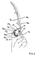
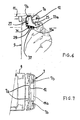
figures 4 et5 sont des coupes respectivement selon IV-IV et V-V de lafigure 2 , dans un état monté des éléments, couvercle ouvert, organe charnière monté, - la
figure 6 est une coupe selon V-V de lafigure 2 , dans un état monté des éléments, couvercle fermé, - et la
figure 7 est une coupe selon VII-VII de lafigure 2 , dans un état monté des éléments. - Sur la
figure 1 , est représenté un exemple d'implantation d'un bac de rangement 1 à disposer dans l'habitacle 3 d'un véhicule 5, ici une automobile. - Comme il est représenté à la
figure 2 , le bac comprend un organe charnière 7, un corps 9 en plastique et un couvercle 11. - L'organe charnière comprend une première et une deuxième parties 7a,7b en matière plastique montées pivotantes l'une par rapport à l'autre autour d'un arbre 12.
- Le bac est monté entre le siège conducteur 40a du véhicule 5 et le siège passager 40b situé à côté de lui.
- Le bac définit ainsi la console centrale de ce véhicule, avec son couvercle 11 disposé à une hauteur H adaptée pour servir d'appui-coude, en position fermée, alors que la première partie 7a de l'organe charnière est rabattue à plat sur la seconde partie 7b.
- Le corps 9 et le couvercle 11 sont liés ensemble, à pivotement, par l'organe de charnière 7.
- Le couvercle 11 comprend un insert en plastique rigide 11a et une fine peau (extérieure) d'aspect 11b, typiquement en plastique souple surmoulé, ou en cuir fixé à l'insert.
- La première partie 7a est fixée à l'insert 11a, notamment par les clips 10 ; cf.
fig.2 . - Favorablement, et comme illustré
figs.5 ,6 , l'arbre 12 sera localement porté par cet insert.Fig.4 , on voit qu'ailleurs, l'arbre 12 est localement maintenu dans un canal 70a de la première partie 7a de l'organe de charnière. - La
fig.7 détaille également le montage avec la partie 7b. Cette seconde partie 7b présente par ailleurs plusieurs plots saillants 13a, 13b engagés dans des cavités 15a, 15b du corps 9 du bac pour y être maintenus fixement ; cf.fig.3 notamment. - Les plots 13a, 13b comprennent des ergots 17a, 17b de verrouillage dont l'engagement, suivant une direction prédéterminée E, dans les zones en creux 19a, 19b formées dans les cavités 15a, 15b du corps du bac en empêche le retrait ultérieur ; cf. notamment
fig.3 . - Des moyens complémentaires de fixation, tels 21a (
fig.5 ) sont montés entre le corps 9 et la seconde partie 7b de l'organe charnière, pour les fixer ensemble, une fois les ergots 17a, 17b verrouillés dans les zones en creux 19a, 19b. - La seconde partie 7b de charnière présente, à un niveau situé au-dessus des plots saillants 13a, 13b, une forme intérieurement concave 23 face à laquelle se déplace, avec le pivotement de la première partie 7a de l'élément de charnière par rapport à la seconde, une zone 25 de cette première partie de charnière 7a.
- La zone 25 forme une lame convexe définissant localement une butée 25a de retenue du couvercle 11 lorsqu'en pivotant dans un sens (ouverture par basculement vers l'arrière) par rapport au corps 9 du bac, une portion de la lame 25 vient buter contre une partie terminale 23a de ladite forme intérieurement concave 23 de la seconde partie 7b de charnière ; cf.
fig.4 . - Localement (
fig.5 ), la lame convexe 25 présente un doigt 25b engageant de façon forcée une première extrémité 27a1 d'une lamelle élastique 27, au-delà d'un épaulement 27b de celle-ci, dans une position de pleine ouverture du couvercle 11. - La lamelle élastique 27, ici métallique, est fixée à la seconde partie 7b de l'organe charnière, vers sa seconde extrémité 27a2.
- Cette seconde partie 7b présente, en partie inférieure et à l'écart des plots 13a, 13b, une paroi de fond 29 sous laquelle font saillie au moins un pion de centrage 31 et des pions taraudés, tels 33a.
- Ces derniers coïncident avec des orifices, tels 35a, ménagés dans le corps 9 du bac, les deux recevant par-dessous des vis, telles que 37, communes de fixation, pour définir une partie au moins des moyens complémentaires de fixation précités.
- Le/chaque plot, tel 13a, et la cavité, telle 15a, qui le reçoit présentent des parois latérales (ici arrière ; cf.
fig.3 ), telles respectivement 130a, 150a, de guidage inclinées par rapport à la verticale et s'étendant vers le bas (extrémité libre). On remarquera, notammentfig.3 , que ces parois 130a, 150a sont favorablement adjacentes aux parois (ici de côté) pourvues respectivement des ergots (tels 17a) et des zones en creux (telles 19a). - Eventuellement le bac de l'invention pourrait être monté ailleurs dans le véhicule, comme par exemple au milieu de la banquette arrière.
Claims (8)
- Bac de rangement à disposer dans l'habitacle d'un véhicule, le bac comprenant un organe charnière (7), un corps (9) en plastique et un couvercle (11), le corps et le couvercle étant liés ensemble, à pivotement, par l'organe de charnière, caractérisé en ce que l'organe charnière comprend une première et une deuxième parties (7a,7b) en matière plastique montées pivotantes l'une par rapport à l'autre autour d'un arbre (12), la première partie étant fixée à l'insert(11a) du couvercle(11), la seconde partie présentant plusieurs plots saillants (13a,13b) engagés dans des cavités(15a,15b) du corps(9) du bac pour y être maintenus, les plots comprenant des ergots(17a,17b) de verrouillage dont l'engagement, suivant une direction prédéterminée, dans des zones en creux (19a,19b) formées dans lesdites cavités est apte à en empêcher le retrait ultérieur, des moyens complémentaires de fixation (21a,37) montés entre le corps(9) du bac et la seconde partie(7b) de l'organe charnière étant adaptés à les fixer ensemble, une fois les ergots verrouillés dans lesdites zones en creux.
- Bac selon la revendication 1, caractérisé en ce que la seconde partie(7b) de charnière présente, à un niveau situé au-dessus des plots saillants(13a,13b), une forme intérieurement concave(23) face à laquelle, une zone(25) de ladite première partie de charnière formant une lame convexe est apte à se déplacer avec le pivotement de la première partie de l'élément de charnière par rapport à la seconde, ladite zone(25) de la première partie étant apte à définir localement une butée(25a) de retenue du couvercle, lorsqu'en pivotant dans un sens par rapport au corps du bac une portion de ladite lame vient buter contre une partie terminale de ladite forme intérieurement concave de la seconde partie de charnière.
- Bac selon la revendication 1 ou 2, caractérisé en ce que, localement, la lame convexe présente un doigt(25b) apte à engager de façon forcée une première extrémité d'une lamelle élastique(27), au-delà d'un épaulement(27b) de celle-ci, dans une position de pleine ouverture du couvercle(11), la lamelle élastique étant fixée à la seconde partie de l'organe charnière, vers sa seconde extrémité.
- Bac selon l'une des revendications précédentes, caractérisé en ce que la seconde partie de l'organe charnière présente, en partie inférieure et à l'écart des plots, une paroi de fond sous laquelle font saillie au moins un pion de centrage et des pions taraudés, ces derniers coïncidant avec des orifices ménagés dans le corps du bac, les pions de centrage et les pions taraudés recevant par-dessous des vis communes de fixation.
- Bac selon l'une des revendications précédentes, caractérisé en ce que le/chaque plot et la cavité qui le reçoit présentent des parois latérales de guidage (130a,150a) inclinées par rapport à la verticale et adjacentes aux parois pourvues respectivement des ergots (17a,17b) et des zones en creux (19a,19b).
- Bac selon l'une des revendications précédentes, caractérisé en ce que la première partie de l'organe charnière est fixée à l'insert et en ce que l'arbre(12) est porté par cet insert.
- Bac selon l'une des revendications 1 à 5, caractérisé en ce que l'arbre (12) est localement maintenu dans un canal (70a) de la première partie (7a) de l'organe charnière.
- Véhicule automobile, caractérisé en ce qu'il comprend un habitacle dans lequel un bac selon l'une des revendications précédentes est monté entre le siège conducteur du véhicule et le siège passager situé à côté de lui, le bac définissant alors la console centrale de ce véhicule, avec son couvercle disposé à une hauteur adaptée pour servir d'appui-coude, en position fermée, alors que la première partie de l'organe charnière est rabattue à plat sur la seconde.
Applications Claiming Priority (1)
| Application Number | Priority Date | Filing Date | Title |
|---|---|---|---|
| FR0850671A FR2927032B1 (fr) | 2008-02-04 | 2008-02-04 | Bac de rangement pour vehicule. |
Publications (2)
| Publication Number | Publication Date |
|---|---|
| EP2085267A1 true EP2085267A1 (fr) | 2009-08-05 |
| EP2085267B1 EP2085267B1 (fr) | 2010-12-22 |
Family
ID=39864908
Family Applications (1)
| Application Number | Title | Priority Date | Filing Date |
|---|---|---|---|
| EP09305098A Not-in-force EP2085267B1 (fr) | 2008-02-04 | 2009-02-02 | Bac de rangement pour véhicule |
Country Status (5)
| Country | Link |
|---|---|
| EP (1) | EP2085267B1 (fr) |
| AT (1) | ATE492431T1 (fr) |
| DE (1) | DE602009000440D1 (fr) |
| ES (1) | ES2354860T3 (fr) |
| FR (1) | FR2927032B1 (fr) |
Cited By (3)
| Publication number | Priority date | Publication date | Assignee | Title |
|---|---|---|---|---|
| CN102259620A (zh) * | 2011-04-13 | 2011-11-30 | 浙江吉利汽车研究院有限公司 | 一种汽车扶手箱 |
| CN106828225A (zh) * | 2016-12-21 | 2017-06-13 | 宁波继峰汽车零部件股份有限公司 | 一种方便使用者后备箱取物的智能化汽车后排扶手 |
| EP3246199A1 (fr) * | 2016-05-20 | 2017-11-22 | Grammer Ag | Accoudoir |
Citations (2)
| Publication number | Priority date | Publication date | Assignee | Title |
|---|---|---|---|---|
| US20060237985A1 (en) * | 2003-01-16 | 2006-10-26 | Scheerhorn Daniel J | Snap-in coupling assembly |
| FR2886898A1 (fr) * | 2005-06-09 | 2006-12-15 | Plasthom S A Sa | Accoudoir multi-positions associe a un bac de rangement, notamment pour vehicule automobile |
-
2008
- 2008-02-04 FR FR0850671A patent/FR2927032B1/fr not_active Expired - Fee Related
-
2009
- 2009-02-02 EP EP09305098A patent/EP2085267B1/fr not_active Not-in-force
- 2009-02-02 ES ES09305098T patent/ES2354860T3/es active Active
- 2009-02-02 DE DE602009000440T patent/DE602009000440D1/de active Active
- 2009-02-02 AT AT09305098T patent/ATE492431T1/de not_active IP Right Cessation
Patent Citations (2)
| Publication number | Priority date | Publication date | Assignee | Title |
|---|---|---|---|---|
| US20060237985A1 (en) * | 2003-01-16 | 2006-10-26 | Scheerhorn Daniel J | Snap-in coupling assembly |
| FR2886898A1 (fr) * | 2005-06-09 | 2006-12-15 | Plasthom S A Sa | Accoudoir multi-positions associe a un bac de rangement, notamment pour vehicule automobile |
Cited By (9)
| Publication number | Priority date | Publication date | Assignee | Title |
|---|---|---|---|---|
| CN102259620A (zh) * | 2011-04-13 | 2011-11-30 | 浙江吉利汽车研究院有限公司 | 一种汽车扶手箱 |
| CN102259620B (zh) * | 2011-04-13 | 2012-11-28 | 浙江吉利汽车研究院有限公司 | 一种汽车扶手箱 |
| EP3246199A1 (fr) * | 2016-05-20 | 2017-11-22 | Grammer Ag | Accoudoir |
| US20170334323A1 (en) * | 2016-05-20 | 2017-11-23 | Grammer Ag | Armrest |
| CN107399255A (zh) * | 2016-05-20 | 2017-11-28 | 格瑞玛股份公司 | 扶手 |
| US10562424B2 (en) * | 2016-05-20 | 2020-02-18 | Grammer Ag | Armrest |
| CN107399255B (zh) * | 2016-05-20 | 2020-05-05 | 格瑞玛股份公司 | 扶手 |
| CN106828225A (zh) * | 2016-12-21 | 2017-06-13 | 宁波继峰汽车零部件股份有限公司 | 一种方便使用者后备箱取物的智能化汽车后排扶手 |
| CN106828225B (zh) * | 2016-12-21 | 2023-11-07 | 宁波继峰汽车零部件股份有限公司 | 一种方便使用者后备箱取物的智能化汽车后排扶手 |
Also Published As
| Publication number | Publication date |
|---|---|
| EP2085267B1 (fr) | 2010-12-22 |
| DE602009000440D1 (de) | 2011-02-03 |
| FR2927032A1 (fr) | 2009-08-07 |
| ATE492431T1 (de) | 2011-01-15 |
| FR2927032B1 (fr) | 2010-09-10 |
| ES2354860T3 (es) | 2011-03-18 |
Similar Documents
| Publication | Publication Date | Title |
|---|---|---|
| EP2085267B1 (fr) | Bac de rangement pour véhicule | |
| EP0964973B1 (fr) | Automobile pourvue d'une bequille de soutien pour le capot | |
| EP2833004B1 (fr) | Support d'agrafe | |
| FR2761422A1 (fr) | Dispositif de fixation d'un element quelconque, tel qu'une poignee, sur une paroi | |
| EP2682546B1 (fr) | Ensemble de rangement pour véhicule et planche de bord comprenant un tel ensemble | |
| JP4634424B2 (ja) | 開閉体のオープンスイッチ構造 | |
| FR2729109A1 (fr) | Dispositif de rangement d'objets notamment pour vehicule automobile | |
| EP2802485B1 (fr) | Dispositif d'habillage lateral d'un coffre arriere de vehicule | |
| EP1663697B1 (fr) | Dispositif de verrouillage de siege automobile amovible | |
| FR2982558A3 (fr) | Logement de rangement pour un pene de ceinture de securite | |
| EP4351926B1 (fr) | Véhicule automobile comprenant un ouvrant avec une cavité de rangement pour un article d'équipement | |
| EP1666309A1 (fr) | Clip pour fixation d'un enjoliveur de pavillon d'un véhicule, ensembles formés par de tels clips et un enjoliveur de pavillon, et véhicule les comportant | |
| EP1302366A1 (fr) | Dispositif d'aménagement d'un volume de rangement pour un habitacle de véhicule automobile | |
| EP1733917A2 (fr) | Siège de véhicule automobile | |
| EP3778284B1 (fr) | Ensemble de fixation pour fixer au moins deux pièces entre elles | |
| FR2907726A3 (fr) | Console centrale de vehicule automobile | |
| FR3135022A1 (fr) | Ensemble d’habillage à planche de bord avec interface de maintenance à levier de déverrouillage | |
| FR3085641A1 (fr) | Systeme de fixation de support d’appareil electronique portable dans un habitacle de vehicule | |
| FR2706409A1 (fr) | Dispositif d'accrochage réversible d'un siège sur un plancher de véhicule automobile. | |
| EP1736366B1 (fr) | Agencement pour le montage d'un panneau d'habillage le long d'une tôle de caisse de véhicule automobile et pièce de montage pour un tel agencement | |
| EP1958822A1 (fr) | Dispositif de rangement pour porte de vehicule automobile | |
| FR3118742A1 (fr) | Rideau de fermeture d’un réceptacle | |
| WO2014186844A1 (fr) | Poubelle pour vehicules | |
| EP1452373A1 (fr) | Elément de fixation d'extrémité de joint de porte | |
| FR2913383A1 (fr) | Agencement pour la fixation d'une boite a gants sur un element de structure d'un vehicule automobile. |
Legal Events
| Date | Code | Title | Description |
|---|---|---|---|
| PUAI | Public reference made under article 153(3) epc to a published international application that has entered the european phase |
Free format text: ORIGINAL CODE: 0009012 |
|
| AK | Designated contracting states |
Kind code of ref document: A1 Designated state(s): AT BE BG CH CY CZ DE DK EE ES FI FR GB GR HR HU IE IS IT LI LT LU LV MC MK MT NL NO PL PT RO SE SI SK TR |
|
| AX | Request for extension of the european patent |
Extension state: AL BA RS |
|
| 17P | Request for examination filed |
Effective date: 20091203 |
|
| 17Q | First examination report despatched |
Effective date: 20100120 |
|
| AKX | Designation fees paid |
Designated state(s): AT BE BG CH CY CZ DE DK EE ES FI FR GB GR HR HU IE IS IT LI LT LU LV MC MK MT NL NO PL PT RO SE SI SK TR |
|
| GRAP | Despatch of communication of intention to grant a patent |
Free format text: ORIGINAL CODE: EPIDOSNIGR1 |
|
| GRAS | Grant fee paid |
Free format text: ORIGINAL CODE: EPIDOSNIGR3 |
|
| GRAA | (expected) grant |
Free format text: ORIGINAL CODE: 0009210 |
|
| AK | Designated contracting states |
Kind code of ref document: B1 Designated state(s): AT BE BG CH CY CZ DE DK EE ES FI FR GB GR HR HU IE IS IT LI LT LU LV MC MK MT NL NO PL PT RO SE SI SK TR |
|
| REG | Reference to a national code |
Ref country code: GB Ref legal event code: FG4D Free format text: NOT ENGLISH |
|
| REG | Reference to a national code |
Ref country code: CH Ref legal event code: EP |
|
| REG | Reference to a national code |
Ref country code: IE Ref legal event code: FG4D |
|
| REF | Corresponds to: |
Ref document number: 602009000440 Country of ref document: DE Date of ref document: 20110203 Kind code of ref document: P |
|
| REG | Reference to a national code |
Ref country code: DE Ref legal event code: R096 Ref document number: 602009000440 Country of ref document: DE Effective date: 20110203 |
|
| REG | Reference to a national code |
Ref country code: ES Ref legal event code: FG2A Effective date: 20110308 |
|
| REG | Reference to a national code |
Ref country code: NL Ref legal event code: VDEP Effective date: 20101222 |
|
| PG25 | Lapsed in a contracting state [announced via postgrant information from national office to epo] |
Ref country code: LT Free format text: LAPSE BECAUSE OF FAILURE TO SUBMIT A TRANSLATION OF THE DESCRIPTION OR TO PAY THE FEE WITHIN THE PRESCRIBED TIME-LIMIT Effective date: 20101222 |
|
| LTIE | Lt: invalidation of european patent or patent extension |
Effective date: 20101222 |
|
| PG25 | Lapsed in a contracting state [announced via postgrant information from national office to epo] |
Ref country code: SI Free format text: LAPSE BECAUSE OF FAILURE TO SUBMIT A TRANSLATION OF THE DESCRIPTION OR TO PAY THE FEE WITHIN THE PRESCRIBED TIME-LIMIT Effective date: 20101222 Ref country code: CY Free format text: LAPSE BECAUSE OF FAILURE TO SUBMIT A TRANSLATION OF THE DESCRIPTION OR TO PAY THE FEE WITHIN THE PRESCRIBED TIME-LIMIT Effective date: 20101222 Ref country code: FI Free format text: LAPSE BECAUSE OF FAILURE TO SUBMIT A TRANSLATION OF THE DESCRIPTION OR TO PAY THE FEE WITHIN THE PRESCRIBED TIME-LIMIT Effective date: 20101222 Ref country code: SE Free format text: LAPSE BECAUSE OF FAILURE TO SUBMIT A TRANSLATION OF THE DESCRIPTION OR TO PAY THE FEE WITHIN THE PRESCRIBED TIME-LIMIT Effective date: 20101222 Ref country code: HR Free format text: LAPSE BECAUSE OF FAILURE TO SUBMIT A TRANSLATION OF THE DESCRIPTION OR TO PAY THE FEE WITHIN THE PRESCRIBED TIME-LIMIT Effective date: 20101222 Ref country code: AT Free format text: LAPSE BECAUSE OF FAILURE TO SUBMIT A TRANSLATION OF THE DESCRIPTION OR TO PAY THE FEE WITHIN THE PRESCRIBED TIME-LIMIT Effective date: 20101222 Ref country code: LV Free format text: LAPSE BECAUSE OF FAILURE TO SUBMIT A TRANSLATION OF THE DESCRIPTION OR TO PAY THE FEE WITHIN THE PRESCRIBED TIME-LIMIT Effective date: 20101222 Ref country code: BG Free format text: LAPSE BECAUSE OF FAILURE TO SUBMIT A TRANSLATION OF THE DESCRIPTION OR TO PAY THE FEE WITHIN THE PRESCRIBED TIME-LIMIT Effective date: 20110322 |
|
| REG | Reference to a national code |
Ref country code: IE Ref legal event code: FD4D |
|
| PG25 | Lapsed in a contracting state [announced via postgrant information from national office to epo] |
Ref country code: IS Free format text: LAPSE BECAUSE OF FAILURE TO SUBMIT A TRANSLATION OF THE DESCRIPTION OR TO PAY THE FEE WITHIN THE PRESCRIBED TIME-LIMIT Effective date: 20110422 Ref country code: PT Free format text: LAPSE BECAUSE OF FAILURE TO SUBMIT A TRANSLATION OF THE DESCRIPTION OR TO PAY THE FEE WITHIN THE PRESCRIBED TIME-LIMIT Effective date: 20110422 Ref country code: EE Free format text: LAPSE BECAUSE OF FAILURE TO SUBMIT A TRANSLATION OF THE DESCRIPTION OR TO PAY THE FEE WITHIN THE PRESCRIBED TIME-LIMIT Effective date: 20101222 Ref country code: CZ Free format text: LAPSE BECAUSE OF FAILURE TO SUBMIT A TRANSLATION OF THE DESCRIPTION OR TO PAY THE FEE WITHIN THE PRESCRIBED TIME-LIMIT Effective date: 20101222 Ref country code: NO Free format text: LAPSE BECAUSE OF FAILURE TO SUBMIT A TRANSLATION OF THE DESCRIPTION OR TO PAY THE FEE WITHIN THE PRESCRIBED TIME-LIMIT Effective date: 20110322 Ref country code: GR Free format text: LAPSE BECAUSE OF FAILURE TO SUBMIT A TRANSLATION OF THE DESCRIPTION OR TO PAY THE FEE WITHIN THE PRESCRIBED TIME-LIMIT Effective date: 20110323 |
|
| BERE | Be: lapsed |
Owner name: RENAULT S.A.S. Effective date: 20110228 |
|
| PG25 | Lapsed in a contracting state [announced via postgrant information from national office to epo] |
Ref country code: SK Free format text: LAPSE BECAUSE OF FAILURE TO SUBMIT A TRANSLATION OF THE DESCRIPTION OR TO PAY THE FEE WITHIN THE PRESCRIBED TIME-LIMIT Effective date: 20101222 Ref country code: RO Free format text: LAPSE BECAUSE OF FAILURE TO SUBMIT A TRANSLATION OF THE DESCRIPTION OR TO PAY THE FEE WITHIN THE PRESCRIBED TIME-LIMIT Effective date: 20101222 Ref country code: NL Free format text: LAPSE BECAUSE OF FAILURE TO SUBMIT A TRANSLATION OF THE DESCRIPTION OR TO PAY THE FEE WITHIN THE PRESCRIBED TIME-LIMIT Effective date: 20101222 Ref country code: PL Free format text: LAPSE BECAUSE OF FAILURE TO SUBMIT A TRANSLATION OF THE DESCRIPTION OR TO PAY THE FEE WITHIN THE PRESCRIBED TIME-LIMIT Effective date: 20101222 |
|
| PG25 | Lapsed in a contracting state [announced via postgrant information from national office to epo] |
Ref country code: MC Free format text: LAPSE BECAUSE OF NON-PAYMENT OF DUE FEES Effective date: 20110228 |
|
| PLBE | No opposition filed within time limit |
Free format text: ORIGINAL CODE: 0009261 |
|
| STAA | Information on the status of an ep patent application or granted ep patent |
Free format text: STATUS: NO OPPOSITION FILED WITHIN TIME LIMIT |
|
| PG25 | Lapsed in a contracting state [announced via postgrant information from national office to epo] |
Ref country code: DK Free format text: LAPSE BECAUSE OF FAILURE TO SUBMIT A TRANSLATION OF THE DESCRIPTION OR TO PAY THE FEE WITHIN THE PRESCRIBED TIME-LIMIT Effective date: 20101222 Ref country code: IE Free format text: LAPSE BECAUSE OF FAILURE TO SUBMIT A TRANSLATION OF THE DESCRIPTION OR TO PAY THE FEE WITHIN THE PRESCRIBED TIME-LIMIT Effective date: 20101222 |
|
| 26N | No opposition filed |
Effective date: 20110923 |
|
| PG25 | Lapsed in a contracting state [announced via postgrant information from national office to epo] |
Ref country code: BE Free format text: LAPSE BECAUSE OF NON-PAYMENT OF DUE FEES Effective date: 20110228 |
|
| PG25 | Lapsed in a contracting state [announced via postgrant information from national office to epo] |
Ref country code: MT Free format text: LAPSE BECAUSE OF FAILURE TO SUBMIT A TRANSLATION OF THE DESCRIPTION OR TO PAY THE FEE WITHIN THE PRESCRIBED TIME-LIMIT Effective date: 20101222 |
|
| REG | Reference to a national code |
Ref country code: DE Ref legal event code: R097 Ref document number: 602009000440 Country of ref document: DE Effective date: 20110923 |
|
| PG25 | Lapsed in a contracting state [announced via postgrant information from national office to epo] |
Ref country code: MK Free format text: LAPSE BECAUSE OF FAILURE TO SUBMIT A TRANSLATION OF THE DESCRIPTION OR TO PAY THE FEE WITHIN THE PRESCRIBED TIME-LIMIT Effective date: 20101222 |
|
| PG25 | Lapsed in a contracting state [announced via postgrant information from national office to epo] |
Ref country code: LU Free format text: LAPSE BECAUSE OF NON-PAYMENT OF DUE FEES Effective date: 20110202 |
|
| PG25 | Lapsed in a contracting state [announced via postgrant information from national office to epo] |
Ref country code: TR Free format text: LAPSE BECAUSE OF FAILURE TO SUBMIT A TRANSLATION OF THE DESCRIPTION OR TO PAY THE FEE WITHIN THE PRESCRIBED TIME-LIMIT Effective date: 20101222 |
|
| REG | Reference to a national code |
Ref country code: CH Ref legal event code: PL |
|
| PG25 | Lapsed in a contracting state [announced via postgrant information from national office to epo] |
Ref country code: CH Free format text: LAPSE BECAUSE OF NON-PAYMENT OF DUE FEES Effective date: 20130228 Ref country code: LI Free format text: LAPSE BECAUSE OF NON-PAYMENT OF DUE FEES Effective date: 20130228 Ref country code: HU Free format text: LAPSE BECAUSE OF FAILURE TO SUBMIT A TRANSLATION OF THE DESCRIPTION OR TO PAY THE FEE WITHIN THE PRESCRIBED TIME-LIMIT Effective date: 20101222 |
|
| REG | Reference to a national code |
Ref country code: FR Ref legal event code: PLFP Year of fee payment: 7 |
|
| REG | Reference to a national code |
Ref country code: FR Ref legal event code: PLFP Year of fee payment: 8 |
|
| REG | Reference to a national code |
Ref country code: FR Ref legal event code: PLFP Year of fee payment: 9 |
|
| REG | Reference to a national code |
Ref country code: FR Ref legal event code: PLFP Year of fee payment: 10 |
|
| PGFP | Annual fee paid to national office [announced via postgrant information from national office to epo] |
Ref country code: GB Payment date: 20220223 Year of fee payment: 14 Ref country code: DE Payment date: 20220217 Year of fee payment: 14 |
|
| PGFP | Annual fee paid to national office [announced via postgrant information from national office to epo] |
Ref country code: IT Payment date: 20220218 Year of fee payment: 14 Ref country code: FR Payment date: 20220217 Year of fee payment: 14 |
|
| PGFP | Annual fee paid to national office [announced via postgrant information from national office to epo] |
Ref country code: ES Payment date: 20220426 Year of fee payment: 14 |
|
| REG | Reference to a national code |
Ref country code: DE Ref legal event code: R119 Ref document number: 602009000440 Country of ref document: DE |
|
| GBPC | Gb: european patent ceased through non-payment of renewal fee |
Effective date: 20230202 |
|
| PG25 | Lapsed in a contracting state [announced via postgrant information from national office to epo] |
Ref country code: GB Free format text: LAPSE BECAUSE OF NON-PAYMENT OF DUE FEES Effective date: 20230202 |
|
| PG25 | Lapsed in a contracting state [announced via postgrant information from national office to epo] |
Ref country code: IT Free format text: LAPSE BECAUSE OF NON-PAYMENT OF DUE FEES Effective date: 20230202 Ref country code: GB Free format text: LAPSE BECAUSE OF NON-PAYMENT OF DUE FEES Effective date: 20230202 Ref country code: FR Free format text: LAPSE BECAUSE OF NON-PAYMENT OF DUE FEES Effective date: 20230228 Ref country code: DE Free format text: LAPSE BECAUSE OF NON-PAYMENT OF DUE FEES Effective date: 20230901 |
|
| REG | Reference to a national code |
Ref country code: ES Ref legal event code: FD2A Effective date: 20240404 |
|
| PG25 | Lapsed in a contracting state [announced via postgrant information from national office to epo] |
Ref country code: ES Free format text: LAPSE BECAUSE OF NON-PAYMENT OF DUE FEES Effective date: 20230203 |
|
| PG25 | Lapsed in a contracting state [announced via postgrant information from national office to epo] |
Ref country code: ES Free format text: LAPSE BECAUSE OF NON-PAYMENT OF DUE FEES Effective date: 20230203 |