EP2085196B1 - Mitre Saw with Top Table - Google Patents
Mitre Saw with Top Table Download PDFInfo
- Publication number
- EP2085196B1 EP2085196B1 EP09160907.3A EP09160907A EP2085196B1 EP 2085196 B1 EP2085196 B1 EP 2085196B1 EP 09160907 A EP09160907 A EP 09160907A EP 2085196 B1 EP2085196 B1 EP 2085196B1
- Authority
- EP
- European Patent Office
- Prior art keywords
- saw
- motor unit
- guard
- pivotal guard
- rearward
- Prior art date
- Legal status (The legal status is an assumption and is not a legal conclusion. Google has not performed a legal analysis and makes no representation as to the accuracy of the status listed.)
- Not-in-force
Links
Images


Classifications
-
- B—PERFORMING OPERATIONS; TRANSPORTING
- B27—WORKING OR PRESERVING WOOD OR SIMILAR MATERIAL; NAILING OR STAPLING MACHINES IN GENERAL
- B27B—SAWS FOR WOOD OR SIMILAR MATERIAL; COMPONENTS OR ACCESSORIES THEREFOR
- B27B5/00—Sawing machines working with circular or cylindrical saw blades; Components or equipment therefor
- B27B5/16—Saw benches
- B27B5/165—Convertible sawing devices
-
- B—PERFORMING OPERATIONS; TRANSPORTING
- B23—MACHINE TOOLS; METAL-WORKING NOT OTHERWISE PROVIDED FOR
- B23D—PLANING; SLOTTING; SHEARING; BROACHING; SAWING; FILING; SCRAPING; LIKE OPERATIONS FOR WORKING METAL BY REMOVING MATERIAL, NOT OTHERWISE PROVIDED FOR
- B23D45/00—Sawing machines or sawing devices with circular saw blades or with friction saw discs
- B23D45/04—Sawing machines or sawing devices with circular saw blades or with friction saw discs with a circular saw blade or the stock carried by a pivoted lever
- B23D45/042—Sawing machines or sawing devices with circular saw blades or with friction saw discs with a circular saw blade or the stock carried by a pivoted lever with the saw blade carried by a pivoted lever
- B23D45/046—Sawing machines or sawing devices with circular saw blades or with friction saw discs with a circular saw blade or the stock carried by a pivoted lever with the saw blade carried by a pivoted lever the pivoted lever being mounted on a carriage
- B23D45/048—Sawing machines or sawing devices with circular saw blades or with friction saw discs with a circular saw blade or the stock carried by a pivoted lever with the saw blade carried by a pivoted lever the pivoted lever being mounted on a carriage the saw blade being adjustable according to angle of cut
-
- B—PERFORMING OPERATIONS; TRANSPORTING
- B23—MACHINE TOOLS; METAL-WORKING NOT OTHERWISE PROVIDED FOR
- B23D—PLANING; SLOTTING; SHEARING; BROACHING; SAWING; FILING; SCRAPING; LIKE OPERATIONS FOR WORKING METAL BY REMOVING MATERIAL, NOT OTHERWISE PROVIDED FOR
- B23D47/00—Sawing machines or sawing devices working with circular saw blades, characterised only by constructional features of particular parts
- B23D47/02—Sawing machines or sawing devices working with circular saw blades, characterised only by constructional features of particular parts of frames; of guiding arrangements for work-table or saw-carrier
- B23D47/025—Sawing machines or sawing devices working with circular saw blades, characterised only by constructional features of particular parts of frames; of guiding arrangements for work-table or saw-carrier of tables
-
- B—PERFORMING OPERATIONS; TRANSPORTING
- B27—WORKING OR PRESERVING WOOD OR SIMILAR MATERIAL; NAILING OR STAPLING MACHINES IN GENERAL
- B27B—SAWS FOR WOOD OR SIMILAR MATERIAL; COMPONENTS OR ACCESSORIES THEREFOR
- B27B27/00—Guide fences or stops for timber in saw mills or sawing machines; Measuring equipment thereon
- B27B27/08—Guide fences or stops for timber in saw mills or sawing machines; Measuring equipment thereon arranged adjustably, not limited to only one of the groups B27B27/02 - B27B27/06
-
- B—PERFORMING OPERATIONS; TRANSPORTING
- B27—WORKING OR PRESERVING WOOD OR SIMILAR MATERIAL; NAILING OR STAPLING MACHINES IN GENERAL
- B27B—SAWS FOR WOOD OR SIMILAR MATERIAL; COMPONENTS OR ACCESSORIES THEREFOR
- B27B27/00—Guide fences or stops for timber in saw mills or sawing machines; Measuring equipment thereon
- B27B27/10—Devices for moving or adjusting the guide fences or stops
-
- B—PERFORMING OPERATIONS; TRANSPORTING
- B27—WORKING OR PRESERVING WOOD OR SIMILAR MATERIAL; NAILING OR STAPLING MACHINES IN GENERAL
- B27B—SAWS FOR WOOD OR SIMILAR MATERIAL; COMPONENTS OR ACCESSORIES THEREFOR
- B27B5/00—Sawing machines working with circular or cylindrical saw blades; Components or equipment therefor
- B27B5/16—Saw benches
- B27B5/22—Saw benches with non-feedable circular saw blade
- B27B5/26—Saw benches with non-feedable circular saw blade the table being adjustable according to depth or angle of cut
- B27B5/265—Saw benches with non-feedable circular saw blade the table being adjustable according to depth or angle of cut with the saw blade arranged underneath the work-table
-
- B—PERFORMING OPERATIONS; TRANSPORTING
- B27—WORKING OR PRESERVING WOOD OR SIMILAR MATERIAL; NAILING OR STAPLING MACHINES IN GENERAL
- B27B—SAWS FOR WOOD OR SIMILAR MATERIAL; COMPONENTS OR ACCESSORIES THEREFOR
- B27B5/00—Sawing machines working with circular or cylindrical saw blades; Components or equipment therefor
- B27B5/29—Details; Component parts; Accessories
-
- B—PERFORMING OPERATIONS; TRANSPORTING
- B27—WORKING OR PRESERVING WOOD OR SIMILAR MATERIAL; NAILING OR STAPLING MACHINES IN GENERAL
- B27G—ACCESSORY MACHINES OR APPARATUS FOR WORKING WOOD OR SIMILAR MATERIALS; TOOLS FOR WORKING WOOD OR SIMILAR MATERIALS; SAFETY DEVICES FOR WOOD WORKING MACHINES OR TOOLS
- B27G19/00—Safety guards or devices specially adapted for wood saws; Auxiliary devices facilitating proper operation of wood saws
- B27G19/02—Safety guards or devices specially adapted for wood saws; Auxiliary devices facilitating proper operation of wood saws for circular saws
- B27G19/025—Safety guards or devices specially adapted for wood saws; Auxiliary devices facilitating proper operation of wood saws for circular saws with guards for tool
-
- Y—GENERAL TAGGING OF NEW TECHNOLOGICAL DEVELOPMENTS; GENERAL TAGGING OF CROSS-SECTIONAL TECHNOLOGIES SPANNING OVER SEVERAL SECTIONS OF THE IPC; TECHNICAL SUBJECTS COVERED BY FORMER USPC CROSS-REFERENCE ART COLLECTIONS [XRACs] AND DIGESTS
- Y10—TECHNICAL SUBJECTS COVERED BY FORMER USPC
- Y10T—TECHNICAL SUBJECTS COVERED BY FORMER US CLASSIFICATION
- Y10T83/00—Cutting
- Y10T83/606—Interrelated tool actuating means and guard means
-
- Y—GENERAL TAGGING OF NEW TECHNOLOGICAL DEVELOPMENTS; GENERAL TAGGING OF CROSS-SECTIONAL TECHNOLOGIES SPANNING OVER SEVERAL SECTIONS OF THE IPC; TECHNICAL SUBJECTS COVERED BY FORMER USPC CROSS-REFERENCE ART COLLECTIONS [XRACs] AND DIGESTS
- Y10—TECHNICAL SUBJECTS COVERED BY FORMER USPC
- Y10T—TECHNICAL SUBJECTS COVERED BY FORMER US CLASSIFICATION
- Y10T83/00—Cutting
- Y10T83/748—With work immobilizer
- Y10T83/7593—Work-stop abutment
-
- Y—GENERAL TAGGING OF NEW TECHNOLOGICAL DEVELOPMENTS; GENERAL TAGGING OF CROSS-SECTIONAL TECHNOLOGIES SPANNING OVER SEVERAL SECTIONS OF THE IPC; TECHNICAL SUBJECTS COVERED BY FORMER USPC CROSS-REFERENCE ART COLLECTIONS [XRACs] AND DIGESTS
- Y10—TECHNICAL SUBJECTS COVERED BY FORMER USPC
- Y10T—TECHNICAL SUBJECTS COVERED BY FORMER US CLASSIFICATION
- Y10T83/00—Cutting
- Y10T83/768—Rotatable disc tool pair or tool and carrier
- Y10T83/7684—With means to support work relative to tool[s]
- Y10T83/7693—Tool moved relative to work-support during cutting
- Y10T83/7697—Tool angularly adjustable relative to work-support
-
- Y—GENERAL TAGGING OF NEW TECHNOLOGICAL DEVELOPMENTS; GENERAL TAGGING OF CROSS-SECTIONAL TECHNOLOGIES SPANNING OVER SEVERAL SECTIONS OF THE IPC; TECHNICAL SUBJECTS COVERED BY FORMER USPC CROSS-REFERENCE ART COLLECTIONS [XRACs] AND DIGESTS
- Y10—TECHNICAL SUBJECTS COVERED BY FORMER USPC
- Y10T—TECHNICAL SUBJECTS COVERED BY FORMER US CLASSIFICATION
- Y10T83/00—Cutting
- Y10T83/869—Means to drive or to guide tool
- Y10T83/8773—Bevel or miter cut
Definitions
- the present invention relates to a sliding compound mitre saw as per the preamble of claim 1.
- a sliding compound mitre saw is known from WO98/18588 .
- WO98/18588 discloses a sliding compound mitre saw. Such a saw can perform bevel cuts, mitre cuts, sliding cuts and chop cuts.
- the sliding compound mitre saw disclosed comprises a base 12 (using the same reference numbers as those used in WO98/18588 ) having a rotatable table 14 mounted within it.
- the rotatable table 14, in conjunction with a fence 26 fixed to the base 12, enables the sliding compound mitre saw to perform mitre cuts.
- Connected to the rear of the table 14 is a bevel mount 16 which is able to pivot about a horizontal axis in relation to the table 14. The pivotal movement of the bevel mount 16 in relation to the table 14 enables the sliding compound mitre saw to perform bevel cuts.
- a motor unit 36 which comprises a motor 22 for rotationally driving a circular saw blade 18 mounted on a drive spindle on the motor unit 36.
- the pivotal movement of the motor unit 36 in relation to the guide rods 34 enable the saw to perform chop cuts.
- a fixed guard 40 which surrounds the cutting edge of the top half of the cutting blade 18.
- a pivotal guard 42 Pivotally mounted to the motor unit is a pivotal guard 42 which can pivot between a first position where it surrounds the cutting edge of the lower half of the cutting blade and a retracted position where the cutting edge of the lower half of the blade 18 is exposed for use in cutting.
- the pivotal guard is pivoted between its two positions using a mechanical linkage which comprises a series of mechanical arms 48, 50, which are pivotally connected to each other and the saw, and cams 52, 54 which control the movement of the arms 48, 50.
- a mechanical linkage which comprises a series of mechanical arms 48, 50, which are pivotally connected to each other and the saw, and cams 52, 54 which control the movement of the arms 48, 50.
- JP2005-178281 describes a chop saw with a table mounted on top of the motor unit.
- US5297463 discloses a compound mitre saw having a adjustable work piece support fence.
- a sliding compound mitre saw comprising:
- a “forward pivotal guard”, such as the second forward pivotal guard 220 and the fourth forward pivotal guard, is a blade guard which surrounds the front lower portion of the saw blade when the guard is in its enclosed position.
- a forward blade guard when it moves from its retracted position, where the cutting edge of the cutting blade is exposed, to its enclosing position, where it surrounds the cutting edge of the cutting blade, it rotates, relative to the motor unit 118, in the same direction as the cutting blade when driven by the motor to perform a cutting action.
- a “rearward pivotal guard”, such as the third rearward pivotal guard 232, is a blade guard which surrounds the rear lower portion of the saw blade in its enclosed position.
- the rearward pivotal guard pivots in the same direction as a typical forward pivotal guard.
- the axis of pivot of the rearward pivotal guard is located rearward of the axis of rotation of the saw blade.
- the invention described herein relates to a sliding compound mitre saw, similar to that described in WO98/18588 , which has a table mounted on top of the motor unit to enable the saw to act as a table saw.
- a sliding compound mitre saw with a table 114 which can perform cuts, mitre cuts, sliding cuts and chop cuts.
- the sliding compound mitre saw disclosed comprises a base having a rotatable table 104 mounted within it.
- An extension arm 106 is attached to the periphery of the rotatable table 104 and extends forward in well known manner.
- the rotatable table 104 in conjunction with a fence 108 fixed to the base 102, enables the sliding compound mitre saw to perform mitre cuts.
- a bevel mount 110 Connected to the rear of the rotable table 104 is a bevel mount 110 which is able to pivot about a horizontal axis in relation to the rotatable table 104.
- the pivotal movement of the bevel mount 110 in relation to the rotatable table 14 enables the sliding compound mitre saw to perform bevel cuts.
- Slideably mounted onto the bevel mount 110 are two guide rods 112, 116 which are capable of sliding horizontally, back wards and forwards.
- the rods 112, 116 enable the sliding compound mitre saw to perform sliding cuts.
- Pivotally mounted on the end of the guide rods 112, 116 is a motor unit 118, which comprises a motor (not shown) for rotationally driving a circular saw blade 120 mounted on a drive spindle on the motor unit 118.
- the pivotal movement of the motor unit 118 in relation to the guide rods 112, 116 enable the saw to perform chop cuts.
- the motor unit 118 is biased to an upward position by a spring (not shown).
- a slot 122 extends across the rotatable table 104 and along the extension arm 106.
- a table 114 which enables the sliding compound mitre saw to be also used as a table saw.
- the table 114 is attached to the top side of the motor unit 118.
- a slot 124 is formed through the table 114 through which the top section of the circular saw blade 120 projects.
- the motor unit 118 can be locked in a downward position such that the table 114 is horizontal.
- a work piece such as a piece of wood can then be slid across the top of the table 114 to engage with the top section of the saw blade 120 thus enabling the sliding compound mitre saw to be used as a saw table.
- a riving knife 126 is located towards the rear of the saw blade 120 and a guard 128 can surround the top of the saw blade 120 when the saw is not being used as a table saw, which includes a shoot 130 for the extraction of wood chips.
- the saw comprises a plurality of guards located below the table 114 which are capable of enclosing the lower section of the saw blade for safety purposes when the saw is not being used as a the sliding compound mitre saw for performing chop, mitre, bevel or sliding cuts, for example when the saw is being used as a table saw, with the motor unit 118 locked downwardly.
- Figures 3 to 6 shows a sliding compound mitre saw with a table and with a first example of a guard actuation mechanism not according to claim 1.
- a handle 132 is attached to the motor unit 118 by which a user can grip and pivot the motor unit 118 and the circular saw blade 120 downwards towards the rotatable table 104.
- An electric switch 134 is mounted on the handle 132 for activating the motor.
- the motor unit 118 can be locked in its lowest pivotal position ( Figure 3 ) against the biasing force of the spring. When the motor unit 118 is in this position, the table 114 is horizontal. In this position the table 114 can be used as a table saw, the work piece 216 being cut by the part of the saw blade 120 which passes through the slot 124.
- the saw can be used as a sliding compound mitre saw in the normal manner.
- the height of the table 114, and hence the amount of saw blade 120 passing through it, can be adjusted vertically. This is described in more detail further below.
- the lower part of the circular saw blade 120 below the table 114 is surrounded by a guard actuation assembly.
- a first embodiment of such a guard actuation assembly which will now be described in more detail.
- a "fixed guard”, such as the first fixed guard, is a blade guard which remains stationary relative to the motor unit 118.
- a second forward pivotal guard 220 Pivotally attached to the first fixed guard 218 is a second forward pivotal guard 220.
- the second forward pivotal guard 220 pivots about the axis 222 of the circular saw blade 120.
- a spring biases the second forward pivotal guard 220 downward (clockwise) as shown in figure 3 .
- a roller 224 is mounted on the base of the guard 220. The roller 224 engages either the rotary table 104 or extension 106 or a work piece 216 mounted on the support table 104 or extension 106.
- a bar 226 is pivotally attached at one end to a motor support 208 attached to the end of the guide rails 112, 116.
- An elongate slot 228 is formed along a section of the length of the bar 226 at the other end.
- a pin 230, rigidly attached to the second forward pivotal guard 220 passes through the slot 228 and which is capable of sliding along the slot 228.
- the biasing spring acting on the second forward pivotal guard 220 causes the guard to pivot until the pin 230 is at the inner end position of the slot where it remains held by the force of the spring.
- the pin 230 located within the slot 28 of the bar 26 controls the pivotal movement of the second guard 220 on the housing as it pivots upwards and downwards.
- the second forward pivotal guard 220 surrounds the lower front section of circular saw blade 120.
- the motor unit 118 is pivoted downwardly, the bar 226 pushes the pin 230, causing the second forward pivotal guard 220 to telescopically pivot into the first fixed guard 218.
- the slot 228 allows the guard 220 to pivot freely, against the biasing force of the spring if it encounters a work piece 216 located on the support table 104.
- a third rearward pivotal guard 232 is pivotally mounted about a point 234 on the rear of the first fixed guard 218.
- a spring biases the third rearward pivotal guard 232 backwards (clockwise) as shown in figure 3 .
- a slot (not visible) is formed centrally along the length of the guard 232.
- pivotal downward movement causes the front tip 236 to slide forward, rotating the third rearward pivotal guard 232 about its axis 234 anti-clockwise, the edge of the cutting blade 120 passing through the slot in the third rearward pivotal guard 232 and allowing it to contact a work piece 16 to cut.
- the second forward pivotal guard 220 When the motor unit 118 is pivoted downwardly, the second forward pivotal guard 220 is moved anti-clockwise as shown in Figure 5 , against the biasing force of the spring, by the pin 230 located in the inner end position of the elongate slot 228 of the bar 226.
- the second forward pivotal guard 220 pivots, as the motor unit 118 is pivotally lowered, under the control of the bar 226, until the roller 224 engages the work piece 116 (see Figure 6 ).
- the roller 224 rolls over the top surface of the work piece 216, causing the second forward pivotal guard 220 to pivot at a different rate which would otherwise be caused by the bar 226, resulting in the pin 230 sliding along the elongate slot 228 towards the end located remotely from the bar's pivot point.
- the front lower section of the saw blade 120 becomes exposed to allow it to cut the work piece 216.
- the third rearward pivotal guard 232 pivots once the tip 236 has engaged, allowing the edge of the blade 120 to pass through the third rearward pivotal guard 232, thus exposing the rear lower section of the blade 120 to cut the work piece 216 (see Figure 6 ).
- the second forward pivotal guard 220 is moved as described previously for the first example.
- the second forward pivotal guard is moved using the bar 226 via the pin 230 located within the slot 228.
- an additional fourth forward pivotal guard 320 pivotally mounted about the aperture 324, the wall of which surrounds the drive spindle of the motor unit 118, and into which the second forward pivotal guard can telescope, and which in turn can telescope into the fixed guard 218.
- the guard 320 can freely pivot into and out of, in a telescopic manner, the first fixed guard 218 (see Figure 17 to 21 ).
- Figure 16A to 16E show design drawings of the fourth forward pivotal guard 320.
- the fourth forward pivotal guard 320 is prevented from completely pivoting out of the fixed guard 218 by a catch formed on the fourth forward pivotal guard 320.
- a slot 322 is formed through the side of the fourth forward pivotal guard 320 .
- Figure 15A and 15B show the second forward pivotal guard 220.
- a screw attaches at point 326 on the second forward pivotal guard 220, the body of which passes through the slot 322.
- the screw at point 326 which initially is located at the lowest point within the slot 322, slides along the slot 322 of the fourth forward pivotal guard 320 until it reaches the top end of the slot 322.
- the roller 224 mounts on the peg 328 of the guard 220 as shown in Figure 15A .
- the third rearward pivotal guard 232 moved when it engaged with a work piece, as the housing is pivoted downwardly. However, it has been found that this restricts the visibility of the operator during the use of such a design. It is therefore proposed to move the third rearward pivotal guard using a cam system.
- Figures 8A to 8E show the inner half of the third rearward pivotal guard of the embodiment
- Figures 9A to 9D show the outer half of the third rearward pivotal guard of the embodiment. The two are clamped together to form the guard 232 as shown in Figure 17 to 21 .
- a cam 300 Formed on the bar 226, which is used to pivot the second forward pivotal guard 220, is a cam 300 (see Figures 7 , 17 to 21 ).
- a cam follower 302 in the form of a roller bearing, is mounted on the third rearward pivotal guard 232 at point 350 and which engages with the cam 300.
- a stop 304 is formed next to the cam 300 creating a slot 306 between them in which the cam follower 302 sits when the motor unit 118 is in its upper most position.
- the shape of the slot 306 is such that, when the housing is in its raised position, the cam follower 302 is prevented from moving, thus locking the third rearward pivotal guard 232 against any pivotal movement.
- the cam follower 302 rides out of the slot 306 and over the cam 300 in a direction shown by the arrows in Figure 7 .
- the cam follower 302 is in the position indicated by the dashed lines in Figure 7 .
- the shape of the cam 300 is such to cause the third rearward pivotal guard 232 to initially rise to expose the edge of the blade (to aid visibility) and then fall to engage with the work piece as in the embodiment.
- the table 114 is moveably mounted on the motor unit 118 using a tubular support 440.
- the tubular support 440 allows the table 114 to slide up and down on the motor unit 118.
- a tubular support 440 attached to the edge of the table 114 is a tubular support 440.
- the longitudinal axis of the support 440 is vertical.
- the shape of the cross section of tube 40 is rectangular as best seen in Figures12A and 12B .
- Two vertical slots 442 (only one is visible in Figure 10 ) are formed on opposite sides of the tubular support 440 in a corresponding manner.
- a threaded hole is formed in the metal casting which forms the housing 410 of the motor unit 118.
- a bolt passes through the two slots 442, passing through the width of the tubular support 400 and is threadedly engaged in the hole in the casting of the housing 410. The head of the bolt was sufficiently large to prevent it passing through the slots 442.
- the bolt When the bolt is screwed into the threaded hole, it sandwiches the tubular support 440 against the casting 9as the head of the bolt can not pass through the slots 442) and prevents it being able to slide in a vertical manner.
- the bolt In order to raise the height of the table 114 above the housing 410, the bolt is unscrewed slightly, so that the tubular support 440 can slide vertically, the sliding movement of the bolt along the elongate slot 442 controlling the movement of the tubular support 440. The height is then adjusted and then the bolt tightened to hold the tubular support 440, and hence table 114, stationary.
- the design remains substantially the same. However, the bolt has been replaced by a threaded bar 400 which screws into the metal cast of the housing 410 and a locking knob assembly (described below) which screws onto the threaded bar 400 to sandwich the tubular support 440 against the cast of the housing 410.
- the purpose is to prevent the vertical tubular support 440 from unnecessary movement during height adjustment.
- the assembly comprises a self-locking nut 402 (with nylon insert) being screwed onto the threaded bar 100 which is screwed into the metal cast 410.
- the threaded bar 100 passes through vertical slots 442 in the vertical tubular support 440.
- the nut 402 is screwed onto the bar 400 sandwiching a washer 404 between the nut 402 and the vertical support 440.
- the nut 402 is tightened to apply a predetermined compression force onto the vertical support 440. This allows the support 440 limited movement.
- a cup shaped washer 406 surrounds, but does not engage with the nut 402 which abuts against the washer 404.
- a knob 408 is then screwed onto the threaded shaft 400 to sandwich the cup shaped washer 406 against the washer 404.
- Tightening of the knob 408 results in the vertical support 440 being against the side of the cast 410 to fix its position.
- the slackening of the knob 408 releases the support 440 and allows it to slide.
- the self-locking nut 402 prevents excessive movement of the support 440.
- the slots 502 enable the user to see through the table 114.
- the purpose of the slots is to assist the user when they are using the saw as a sliding compound mitre saw.
- the table 11 blocks the vision of the operator who is trying to cut a work piece below the table 114 on the rotatable table 102 or extension 106 below.
- the slots 502 allow the operator to see "through" the table 114.
- the saw comprises a fence108.
- the fence comprises two halves, a fixed fence 600 on the right as viewed in Figure 22 and a moveable fence 602 on the left as shown in Figure 15 .
- US 5297463 discloses a moveable fence and forms relevant prior art.
- the fence comprises a base section 604 which spans the full width of the saw.
- the base section 604 comprises a straight right section 606, which forms the fixed fence 600 and a straight left section 608 which forms the lower half of the moveable fence 602.
- the two sections 606, 608 are connected to each other by a curved portion 610 (see Figures 17 ).
- the two sections 606, 608 and curved portion 610 are made as a one piece construction and manufactured from cast steel or aluminium. Such a construction is well known in the art.
- the base section 602 is rigidly connected to the base 102 of the saw and transverses the rotatable table 104 in well known manner.
- the straight right section 606 is rigidly fixed to the base 102 and crosses slightly less than half of the right hand side of the rotatable table 104.
- the edge 612 of the fixed fence adjacent the curved portion 610 is vertical.
- the location of the vertical edge 612 is located such that it does not interfere with the blade 120 and blade guards when motor unit 118 is lowered vertically downwardly.
- a bulge 614 is added to the base of the vertical edge 612 which projects towards the moveable fence 602.
- the bulge 614 is the present embodiment is triangular.
- the bulge 614 moves the fence 600 closer to where the blade 120 cuts a work piece. By doing this, it provides support to the rear of a work piece closer to the area where blade 120 cuts through it.
- the remaining vertical edge 612 of the fixed fence 600 is kept at a greater distance from the blade 120 so that it does not interfere with it or the guards.
- the moveable fence comprises two halves, a lower half formed by the straight left straight section 608 of the base section 604 and an upper slideable half 620.
- the upper half 620 can slide in the direction indicated by Arrows A.
- the straight left section 608 is rigidly fixed to the base 102 and crosses slightly less than half of the left hand side of the rotatable table 104.
- a elongate slot Formed in the top of the straight left section along its length is a elongate slot (see Figure 23 which shows a top view of the moveable fence with the upper half 620 removed.)
- a threaded bolt 622 passes through a threaded hole 624 formed in the side of the straight left section 608 from the rear side 626 of the straight left section 608 into the slot 626.
- the base 628 of the upper slideable half 620 is such that it fits into and is capable of sliding along the slot 626.
- Figure 24 shows a sketch of the rear of the top section 620 of the moveable fence.
- Formed in the base 628 of the upper slideable half 620 along the length of the upper half 620 is a groove 630.
- the groove 630 has a first depth D1 long the majority 632 of its length.
- the groove 630 has a second depth D2 along the rest 634 of the groove 630.
- the second depth D2 is less than the first depth D1.
- the end 638 of the bolt 622 is located in the majority 632 of the groove.
- the bolt is prevented from entering the rest 634 by ensuring the end 638 of the bolt 622 is screwed sufficiently far enough into the groove 630 so that it is unable to travel into the rest 634 of the groove 630 as the rest 634 of the groove is too shallow to accommodate the amount of length of the bolt 622 extending into the groove 630.
- the end 638 of the bolt 622 located at this first depth, the movement of the upper half 620 of the sliding fence 602 is restricted by movement of the bolt within the majority 632 of the groove 630 only (the "first range of movement").
- the bolt 622 can then slide the full length of the slot 630, allowing the upper half 620 to slide a greater distance (the "second range of distance").
- the upper half 620 When the bolt 622 is set so that the upper half 620 can travel the first range of movement, the upper half 620 can move towards or away from the cutting blade of the saw. However, the minimum distance between the end 640 of the upper half 620 of the moveable fence 602 and the blade is that same as that for the end 642 of straight left section 608. However, when the bolt 622 is set so that the upper half 620 can travel the second range of movement, the upper half 620 can again move towards or away from the cutting blade of the saw. However, the minimum distance between the end 640 of the upper half 620 of the moveable fence 602 and the blade is now less than that for the end 642 of straight left section 608.
- Figures 25 to 41 show further views of the fences as described above with reference to Figures 22 to 24 .
Landscapes
- Life Sciences & Earth Sciences (AREA)
- Engineering & Computer Science (AREA)
- Mechanical Engineering (AREA)
- Wood Science & Technology (AREA)
- Forests & Forestry (AREA)
- Sawing (AREA)
- Medicines Containing Antibodies Or Antigens For Use As Internal Diagnostic Agents (AREA)
- Vending Machines For Individual Products (AREA)
Abstract
Description
- The present invention relates to a sliding compound mitre saw as per the preamble of claim 1. Such a saw is known from
WO98/18588 -
WO98/18588 EP0875347 ) discloses a sliding compound mitre saw. Such a saw can perform bevel cuts, mitre cuts, sliding cuts and chop cuts. The sliding compound mitre saw disclosed comprises a base 12 (using the same reference numbers as those used inWO98/18588 - Rigidly mounted to the motor unit 36 is a fixed guard 40 which surrounds the cutting edge of the top half of the cutting blade 18. Pivotally mounted to the motor unit is a pivotal guard 42 which can pivot between a first position where it surrounds the cutting edge of the lower half of the cutting blade and a retracted position where the cutting edge of the lower half of the blade 18 is exposed for use in cutting.
- The pivotal guard is pivoted between its two positions using a mechanical linkage which comprises a series of mechanical arms 48, 50, which are pivotally connected to each other and the saw, and cams 52, 54 which control the movement of the arms 48, 50. As the motor unit is pivoted downwards, the mechanical linkage causes the lower cutting edge of the blade to become exposed due to the retraction of the pivotal guard by the mechanical linkage.
-
JP2005-178281 -
US5297463 discloses a compound mitre saw having a adjustable work piece support fence. - Accordingly there is provided a sliding compound mitre saw comprising:
- a base assembly connected to a mounting portion;
- a motor unit pivotally connected to a motor support which is mounted on the mounting portion to allow the motor unit to pivot towards or away from the base assembly to perform chop cuts, wherein the motor support is mounted to two guide rods which are slideably mounted onto the mounting portion to enable the motor support to move relative to the mounting portion to enable the saw to perform sliding cuts, the motor unit having an output drive spindle upon which a circular saw blade can be rigidly mounted to be rotationally driven by the motor unit;
- characterised in that there is further provided at least one rearward pivotal guard pivotally mounted on the motor unit with its axis of pivot located rearward of an axis of rotation of the saw blade the at least one rearward pivotal guard comprising a slot formed centrally along the length of the guard, the at least one rearward pivotal guard being able to pivot from a first enclosed position, where it surrounds at least a rear portion of the lower edge of the saw blade (120) when mounted on the spindle, to a second retracted position where the portion of the lower edge of the saw blade is exposed by passing through the slot; and
- wherein there is further provided a pivotal guard actuating mechanism which moves the at least one rearward pivotal guard from its first enclosed position to its second retracted position when the motor unit is pivoted towards the base assembly;
- wherein there is further provided a table mounted on top of the motor unit to enable the saw to act as a table saw.
- A "forward pivotal guard", such as the second forward pivotal guard 220 and the fourth forward pivotal guard, is a blade guard which surrounds the front lower portion of the saw blade when the guard is in its enclosed position. Typically, a forward blade guard, when it moves from its retracted position, where the cutting edge of the cutting blade is exposed, to its enclosing position, where it surrounds the cutting edge of the cutting blade, it rotates, relative to the motor unit 118, in the same direction as the cutting blade when driven by the motor to perform a cutting action.
- A "rearward pivotal guard", such as the third rearward pivotal guard 232, is a blade guard which surrounds the rear lower portion of the saw blade in its enclosed position. In the embodiment described herein, the rearward pivotal guard pivots in the same direction as a typical forward pivotal guard. However, the axis of pivot of the rearward pivotal guard is located rearward of the axis of rotation of the saw blade.
- An embodiment of the present invention will now be described with reference to the accompanying drawings of which:
-
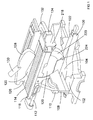
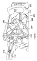
Figure 1 shows a computer generated drawing of the sliding compound mitre saw with a table from a first perspective; -
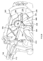
Figure 2 shows a computer generated drawing of the sliding compound mitre saw with a table from a second perspective; -
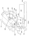
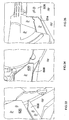
Figure 3 shows a computer generated picture of a side view of the saw showing an example of a guard actuation mechanism and the mechanical linkage which automatically moves the pivotal guards; -
Figure 4 shows a side view of the saw with the blade at its maximum height; -
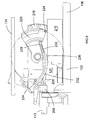
Figure 5 shows a side view of the saw with the blade touching a work piece; -
Figure 6 shows a side view of the saw with the blade cutting the work piece; -
Figure 7 shows a sketch of the cam mechanism of an example of the guard actuation mechanism; -
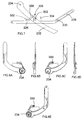
Figure 8A to 8E show a design diagram of the inner half of the third rearward pivotal guard of an example of guard actuation mechanism; -
Figure 9A to 9D show a design diagram of the outer half of the third rearward pivotal guard of an example of guard actuation mechanism; -
Figure 10 shows a computer generated picture of the saw (with the first example of the guard actuating mechanism) with an example of the table height adjustment mechanism; -
Figure 11 shows computer generated picture of a top view of the saw showing the height adjustment mechanism (with the table 114 being shown as transparent); -
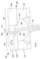
Figure 12A and 12B are engineering drawings of the tubular support; -
Figure 13 shows a sketch of the locking mechanism for a second example of the height adjustment mechanism; -
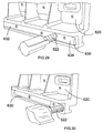
Figure 14 shows a sketch of the table with slots formed through it to enable an operator to see "through" the table to increase visibility of the of the saw below the table114; -
Figures 15A and 15B show the second forward pivotal guard ; -
Figures 16A to 16E show the fourth forward pivotal guard; -
Figure 17 shows a first computer generated picture of the saw from a perspective view with aspects of the saw "cut away" to expose the guard actuation mechanism; -
Figure 18 shows a second computer generated picture of the saw from a perspective view with aspects of the saw "cut away" to expose the guard actuation mechanism; -
Figure 19 shows a third computer generated picture of the saw from a perspective view with aspects of the saw "cut away" to expose the guard actuation mechanism; -
Figure 20 shows a fourth computer generated picture of the saw from a perspective view with aspects of the saw "cut away" to expose the guard actuation mechanism; -
Figure 21 shows a fifth computer generated picture of the saw from a perspective view with aspects of the saw "cut away" to expose the guard actuation mechanism; -
Figure 22 shows a sketch of the front view of the fence 108; -
Figure 23 which shows a top view of the moveable fence with the upper half 620 removed; -
Figure 24 shows a sketch of the rear of the top section of the moveable part of the fence; and -
Figures 25 to 41 show further views of the fences as shown inFigures 22 to 24 . - The invention described herein relates to a sliding compound mitre saw, similar to that described in
WO98/18588 - Referring to
Figures 1 and2 , there is provided a sliding compound mitre saw with a table 114 which can perform cuts, mitre cuts, sliding cuts and chop cuts. The sliding compound mitre saw disclosed comprises a base having a rotatable table 104 mounted within it. An extension arm 106 is attached to the periphery of the rotatable table 104 and extends forward in well known manner. The rotatable table 104, in conjunction with a fence 108 fixed to the base 102, enables the sliding compound mitre saw to perform mitre cuts. Connected to the rear of the rotable table 104 is a bevel mount 110 which is able to pivot about a horizontal axis in relation to the rotatable table 104. The pivotal movement of the bevel mount 110 in relation to the rotatable table 14 enables the sliding compound mitre saw to perform bevel cuts. Slideably mounted onto the bevel mount 110 are two guide rods 112, 116 which are capable of sliding horizontally, back wards and forwards. The rods 112, 116 enable the sliding compound mitre saw to perform sliding cuts. Pivotally mounted on the end of the guide rods 112, 116 is a motor unit 118, which comprises a motor (not shown) for rotationally driving a circular saw blade 120 mounted on a drive spindle on the motor unit 118. The pivotal movement of the motor unit 118 in relation to the guide rods 112, 116 enable the saw to perform chop cuts. The motor unit 118 is biased to an upward position by a spring (not shown). A slot 122 extends across the rotatable table 104 and along the extension arm 106. - Mounted on the top of the saw is a table 114 which enables the sliding compound mitre saw to be also used as a table saw. The table 114 is attached to the top side of the motor unit 118. A slot 124 is formed through the table 114 through which the top section of the circular saw blade 120 projects. The motor unit 118 can be locked in a downward position such that the table 114 is horizontal. A work piece such as a piece of wood can then be slid across the top of the table 114 to engage with the top section of the saw blade 120 thus enabling the sliding compound mitre saw to be used as a saw table. A riving knife 126 is located towards the rear of the saw blade 120 and a guard 128 can surround the top of the saw blade 120 when the saw is not being used as a table saw, which includes a shoot 130 for the extraction of wood chips.
- The saw comprises a plurality of guards located below the table 114 which are capable of enclosing the lower section of the saw blade for safety purposes when the saw is not being used as a the sliding compound mitre saw for performing chop, mitre, bevel or sliding cuts, for example when the saw is being used as a table saw, with the motor unit 118 locked downwardly.
-
Figures 3 to 6 shows a sliding compound mitre saw with a table and with a first example of a guard actuation mechanism not according to claim 1. - Referring to
Figures 3 to 6 , a handle 132 is attached to the motor unit 118 by which a user can grip and pivot the motor unit 118 and the circular saw blade 120 downwards towards the rotatable table 104. An electric switch 134 is mounted on the handle 132 for activating the motor. - The motor unit 118 can be locked in its lowest pivotal position (
Figure 3 ) against the biasing force of the spring. When the motor unit 118 is in this position, the table 114 is horizontal. In this position the table 114 can be used as a table saw, the work piece 216 being cut by the part of the saw blade 120 which passes through the slot 124. - When the motor unit 118 is free to pivot, the saw can be used as a sliding compound mitre saw in the normal manner.
- The height of the table 114, and hence the amount of saw blade 120 passing through it, can be adjusted vertically. This is described in more detail further below.
- The lower part of the circular saw blade 120 below the table 114 is surrounded by a guard actuation assembly. A first embodiment of such a guard actuation assembly which will now be described in more detail.
- Attached to the motor unit 118 is a first fixed guard 218 which surrounds top and middle sections of the circular saw blade 120. A "fixed guard", such as the first fixed guard, is a blade guard which remains stationary relative to the motor unit 118.
- Pivotally attached to the first fixed guard 218 is a second forward pivotal guard 220. The second forward pivotal guard 220 pivots about the axis 222 of the circular saw blade 120. A spring (not shown) biases the second forward pivotal guard 220 downward (clockwise) as shown in
figure 3 . A roller 224 is mounted on the base of the guard 220. The roller 224 engages either the rotary table 104 or extension 106 or a work piece 216 mounted on the support table 104 or extension 106. - A bar 226 is pivotally attached at one end to a motor support 208 attached to the end of the guide rails 112, 116. An elongate slot 228 is formed along a section of the length of the bar 226 at the other end. A pin 230, rigidly attached to the second forward pivotal guard 220 passes through the slot 228 and which is capable of sliding along the slot 228. The biasing spring acting on the second forward pivotal guard 220 causes the guard to pivot until the pin 230 is at the inner end position of the slot where it remains held by the force of the spring. The pin 230 located within the slot 28 of the bar 26 controls the pivotal movement of the second guard 220 on the housing as it pivots upwards and downwards. When the housing 10 is in its upper most pivotal position (
Figure 4 ), the second forward pivotal guard 220 surrounds the lower front section of circular saw blade 120. As the motor unit 118 is pivoted downwardly, the bar 226 pushes the pin 230, causing the second forward pivotal guard 220 to telescopically pivot into the first fixed guard 218. The slot 228 allows the guard 220 to pivot freely, against the biasing force of the spring if it encounters a work piece 216 located on the support table 104. - A third rearward pivotal guard 232 is pivotally mounted about a point 234 on the rear of the first fixed guard 218.
- A spring (not shown) biases the third rearward pivotal guard 232 backwards (clockwise) as shown in
figure 3 . A slot (not visible) is formed centrally along the length of the guard 232. When the motor unit 118 is pivoted to its uppermost position (Figure 4 ), the third rearward pivotal guard 232 pivots to a maximum rearward (clockwise) position where it surrounds the rear of the circular saw blade 120. When the motor unit 118 is pivoted downwardly, the front tip 236 of the third rearward pivotal guard 232 engages with either the support table 104 or a work piece 216 on the support table 104. Once the front tip 236 is engaged, pivotal downward movement causes the front tip 236 to slide forward, rotating the third rearward pivotal guard 232 about its axis 234 anti-clockwise, the edge of the cutting blade 120 passing through the slot in the third rearward pivotal guard 232 and allowing it to contact a work piece 16 to cut. - When the housing is raised to its upper pivot point (
Figure 4 ), the front tip 236 of the third rearward pivotal guard 232 and the rear lower end of the second forward pivotal guard 220 meet so that the whole of the lower section of the cutting blade 120 is surrounded. This, in combination with the fixed guard 218, ensures the whole of the blade 120 surrounded when the motor unit 118 is in the upper position. - When the motor unit 118 is pivoted downwardly, the second forward pivotal guard 220 is moved anti-clockwise as shown in
Figure 5 , against the biasing force of the spring, by the pin 230 located in the inner end position of the elongate slot 228 of the bar 226. The second forward pivotal guard 220 pivots, as the motor unit 118 is pivotally lowered, under the control of the bar 226, until the roller 224 engages the work piece 116 (seeFigure 6 ). As the motor unit 118 continues to pivot downwardly, the roller 224 rolls over the top surface of the work piece 216, causing the second forward pivotal guard 220 to pivot at a different rate which would otherwise be caused by the bar 226, resulting in the pin 230 sliding along the elongate slot 228 towards the end located remotely from the bar's pivot point. Thus the front lower section of the saw blade 120 becomes exposed to allow it to cut the work piece 216. - Similarly, the third rearward pivotal guard 232 pivots once the tip 236 has engaged, allowing the edge of the blade 120 to pass through the third rearward pivotal guard 232, thus exposing the rear lower section of the blade 120 to cut the work piece 216 (see
Figure 6 ). - An embodiment of a guard assembly according to the present invention will now be described in more detail. Where the same features are present in the embodiment which are present in the first example, the same reference numbers have been used. The embodiment is the same as the first example except for:
- the mechanism which moves the third rearward pivotal guard 232 is different; and
- there is an additional fourth forward pivotal guard 320.
- The second forward pivotal guard 220 is moved as described previously for the first example. The second forward pivotal guard is moved using the bar 226 via the pin 230 located within the slot 228. However, unlike the first example, there is now an additional fourth forward pivotal guard 320 pivotally mounted about the aperture 324, the wall of which surrounds the drive spindle of the motor unit 118, and into which the second forward pivotal guard can telescope, and which in turn can telescope into the fixed guard 218. The guard 320 can freely pivot into and out of, in a telescopic manner, the first fixed guard 218 (see
Figure 17 to 21 ).Figure 16A to 16E show design drawings of the fourth forward pivotal guard 320. The fourth forward pivotal guard 320 is prevented from completely pivoting out of the fixed guard 218 by a catch formed on the fourth forward pivotal guard 320. - A slot 322 is formed through the side of the fourth forward pivotal guard 320 .
Figure 15A and 15B show the second forward pivotal guard 220. A screw attaches at point 326 on the second forward pivotal guard 220, the body of which passes through the slot 322. As the second forward pivotal guard pivots, due to the pivoting movement of the motor unit 118 which causes the second forward pivotal guard to pivot due to the bar 226, the screw at point 326, which initially is located at the lowest point within the slot 322, slides along the slot 322 of the fourth forward pivotal guard 320 until it reaches the top end of the slot 322. At which point, the pivotal movement of the second forward pivotal guard 220, which is now located within the fourth forward pivotal guard 320 in a telescopic fashion, causes pivotal movement of the fourth forward pivotal guard 320. The two guards 220, 320 pivotally move in unison inside the fixed guard 218 until the two guards located inside of the fixed guard. - The roller 224 mounts on the peg 328 of the guard 220 as shown in
Figure 15A . - In the first example, the third rearward pivotal guard 232 moved when it engaged with a work piece, as the housing is pivoted downwardly. However, it has been found that this restricts the visibility of the operator during the use of such a design. It is therefore proposed to move the third rearward pivotal guard using a cam system.
-
Figures 8A to 8E show the inner half of the third rearward pivotal guard of the embodiment;Figures 9A to 9D show the outer half of the third rearward pivotal guard of the embodiment. The two are clamped together to form the guard 232 as shown inFigure 17 to 21 . - Formed on the bar 226, which is used to pivot the second forward pivotal guard 220, is a cam 300 (see
Figures 7 ,17 to 21 ). A cam follower 302, in the form of a roller bearing, is mounted on the third rearward pivotal guard 232 at point 350 and which engages with the cam 300. A stop 304 is formed next to the cam 300 creating a slot 306 between them in which the cam follower 302 sits when the motor unit 118 is in its upper most position. The shape of the slot 306 is such that, when the housing is in its raised position, the cam follower 302 is prevented from moving, thus locking the third rearward pivotal guard 232 against any pivotal movement. - As the motor unit 118 is pivoted downwardly causing the bar 226 to move, the cam follower 302 rides out of the slot 306 and over the cam 300 in a direction shown by the arrows in
Figure 7 . When the motor unit 118 is in its lowest position, the cam follower 302 is in the position indicated by the dashed lines inFigure 7 . The shape of the cam 300 is such to cause the third rearward pivotal guard 232 to initially rise to expose the edge of the blade (to aid visibility) and then fall to engage with the work piece as in the embodiment. - When the motor unit 118 rises, the cam 302, retraces its path over the cam 300 on bar 226, closing the third rearward pivotal guard 232. The end of the drive spindle of the motor unit 118 is shown as reference number 289 in
Figure 17 to 21 . - The first example of height adjustment mechanism will now be described with reference to
Figures 10 ,11 and12 . - The table 114 is moveably mounted on the motor unit 118 using a tubular support 440. The tubular support 440 allows the table 114 to slide up and down on the motor unit 118.
- Referring to
Figure 10 , attached to the edge of the table 114 is a tubular support 440. The longitudinal axis of the support 440 is vertical. The shape of the cross section of tube 40 is rectangular as best seen inFigures12A and 12B . Two vertical slots 442 (only one is visible inFigure 10 ) are formed on opposite sides of the tubular support 440 in a corresponding manner. A threaded hole is formed in the metal casting which forms the housing 410 of the motor unit 118. A bolt passes through the two slots 442, passing through the width of the tubular support 400 and is threadedly engaged in the hole in the casting of the housing 410. The head of the bolt was sufficiently large to prevent it passing through the slots 442. - When the bolt is screwed into the threaded hole, it sandwiches the tubular support 440 against the casting 9as the head of the bolt can not pass through the slots 442) and prevents it being able to slide in a vertical manner. In order to raise the height of the table 114 above the housing 410, the bolt is unscrewed slightly, so that the tubular support 440 can slide vertically, the sliding movement of the bolt along the elongate slot 442 controlling the movement of the tubular support 440. The height is then adjusted and then the bolt tightened to hold the tubular support 440, and hence table 114, stationary.
- A second example of the height adjustment mechanism is now described with reference to
Figure 13 . Where the same features are present in the second embodiment which were present in the first, the same reference numbers have been used. - The design remains substantially the same. However, the bolt has been replaced by a threaded bar 400 which screws into the metal cast of the housing 410 and a locking knob assembly (described below) which screws onto the threaded bar 400 to sandwich the tubular support 440 against the cast of the housing 410. The purpose is to prevent the vertical tubular support 440 from unnecessary movement during height adjustment.
- Enclosed you will find at
Figure 13 a sketch of a horizontal cross section of the threaded bar 400 and support 440. - The assembly comprises a self-locking nut 402 (with nylon insert) being screwed onto the threaded bar 100 which is screwed into the metal cast 410. The threaded bar 100 passes through vertical slots 442 in the vertical tubular support 440. The nut 402 is screwed onto the bar 400 sandwiching a washer 404 between the nut 402 and the vertical support 440. The nut 402 is tightened to apply a predetermined compression force onto the vertical support 440. This allows the support 440 limited movement. A cup shaped washer 406 surrounds, but does not engage with the nut 402 which abuts against the washer 404. A knob 408 is then screwed onto the threaded shaft 400 to sandwich the cup shaped washer 406 against the washer 404. Tightening of the knob 408 results in the vertical support 440 being against the side of the cast 410 to fix its position. The slackening of the knob 408 releases the support 440 and allows it to slide. However, the self-locking nut 402 prevents excessive movement of the support 440.
- Referring to
Figure 14 , it is being proposed to add a plurality of slots 502 in the table 114. The slots 502 enable the user to see through the table 114. The purpose of the slots is to assist the user when they are using the saw as a sliding compound mitre saw. When being used in this manner, the table 11 blocks the vision of the operator who is trying to cut a work piece below the table 114 on the rotatable table 102 or extension 106 below. The slots 502 allow the operator to see "through" the table 114. - Referring to
Figure 1 , the saw comprises a fence108. The fence comprises two halves, a fixed fence 600 on the right as viewed inFigure 22 and a moveable fence 602 on the left as shown inFigure 15 .US 5297463 discloses a moveable fence and forms relevant prior art. - The fence comprises a base section 604 which spans the full width of the saw. The base section 604 comprises a straight right section 606, which forms the fixed fence 600 and a straight left section 608 which forms the lower half of the moveable fence 602. The two sections 606, 608 are connected to each other by a curved portion 610 (see
Figures 17 ). The two sections 606, 608 and curved portion 610 are made as a one piece construction and manufactured from cast steel or aluminium. Such a construction is well known in the art. The base section 602 is rigidly connected to the base 102 of the saw and transverses the rotatable table 104 in well known manner. - Referring to the fixed fence 600, the straight right section 606 is rigidly fixed to the base 102 and crosses slightly less than half of the right hand side of the rotatable table 104. The edge 612 of the fixed fence adjacent the curved portion 610 is vertical. The location of the vertical edge 612 is located such that it does not interfere with the blade 120 and blade guards when motor unit 118 is lowered vertically downwardly. A bulge 614 is added to the base of the vertical edge 612 which projects towards the moveable fence 602. The bulge 614 is the present embodiment is triangular. The bulge 614 moves the fence 600 closer to where the blade 120 cuts a work piece. By doing this, it provides support to the rear of a work piece closer to the area where blade 120 cuts through it. However, the remaining vertical edge 612 of the fixed fence 600 is kept at a greater distance from the blade 120 so that it does not interfere with it or the guards.
- Referring to the moveable fence, it comprises two halves, a lower half formed by the straight left straight section 608 of the base section 604 and an upper slideable half 620. The upper half 620 can slide in the direction indicated by Arrows A. As with the straight right section 606, the straight left section 608 is rigidly fixed to the base 102 and crosses slightly less than half of the left hand side of the rotatable table 104. Formed in the top of the straight left section along its length is a elongate slot (see
Figure 23 which shows a top view of the moveable fence with the upper half 620 removed.) A threaded bolt 622 passes through a threaded hole 624 formed in the side of the straight left section 608 from the rear side 626 of the straight left section 608 into the slot 626. The base 628 of the upper slideable half 620 is such that it fits into and is capable of sliding along the slot 626.Figure 24 shows a sketch of the rear of the top section 620 of the moveable fence. Formed in the base 628 of the upper slideable half 620 along the length of the upper half 620 is a groove 630. The groove 630 has a first depth D1 long the majority 632 of its length. The groove 630 has a second depth D2 along the rest 634 of the groove 630. The second depth D2 is less than the first depth D1. When the base 628 of the upper half 620 is located within the groove 630, the groove 630 faces towards the exit 636 of the threaded hole 624 within the slot 626. The bolt 622 is screwed through the hole 624 until its end 638 passes into the slot 626 and then into the groove 630 of the upper half 620. - Whilst the end 638 of the bolt 622 remains in the groove 630, it is prevents the upper half 620 from being separated from the lower half 608 of the moveable fence. Screwing the bolt 622 into the groove 630 until it hits the base of the groove 630, locks the upper half 620 to the lower half 608.
- During normal operation, the end 638 of the bolt 622 is located in the majority 632 of the groove. The bolt is prevented from entering the rest 634 by ensuring the end 638 of the bolt 622 is screwed sufficiently far enough into the groove 630 so that it is unable to travel into the rest 634 of the groove 630 as the rest 634 of the groove is too shallow to accommodate the amount of length of the bolt 622 extending into the groove 630. With the end 638 of the bolt 622 located at this first depth, the movement of the upper half 620 of the sliding fence 602 is restricted by movement of the bolt within the majority 632 of the groove 630 only (the "first range of movement"). If the bolt is then unscrewed slightly, to withdraw the end 638 of the bolt 622 from the groove 630 sufficiently to allow it to travel in the rest 634 of the groove 630, the bolt 622 can then slide the full length of the slot 630, allowing the upper half 620 to slide a greater distance (the "second range of distance").
- When the bolt 622 is set so that the upper half 620 can travel the first range of movement, the upper half 620 can move towards or away from the cutting blade of the saw. However, the minimum distance between the end 640 of the upper half 620 of the moveable fence 602 and the blade is that same as that for the end 642 of straight left section 608. However, when the bolt 622 is set so that the upper half 620 can travel the second range of movement, the upper half 620 can again move towards or away from the cutting blade of the saw. However, the minimum distance between the end 640 of the upper half 620 of the moveable fence 602 and the blade is now less than that for the end 642 of straight left section 608.
- This allows the upper half 620 of a miter saw to have a bypass mode where it goes closer to the blade for precision cuts.
- The advantage of this design of moveable fence is that it allows for a normal type of sliding fence stop for most cutting, while allowing a bypass position which allows the fence to be adjusted closer to the blade when more support is needed. The "stop" between the two regions of travel prevents the user from inadvertently sliding the fence too close to the blade in normal use.
-
Figures 25 to 41 show further views of the fences as described above with reference toFigures 22 to 24 .
Claims (10)
- A sliding compound mitre saw comprising:a base assembly (102, 104) connected to a mounting portion (110);a motor unit (118) pivotally connected to a motor support (208) which is mounted on the mounting portion (110) to allow the motor unit (118) to pivot towards or away from the base assembly (2, 4) to perform chop cuts, wherein the motor support (208) is mounted to two guide rods (112, 116) which are slideably mounted onto the mounting portion (110) to enable the motor support (206) to move relative to the mounting portion (110) to enable the saw to perform sliding cuts, the motor unit (118) having an output drive spindle (289) upon which a circular saw blade (120) can be rigidly mounted to be rotationally driven by the motor unit (118);characterised in that there is further provided at least one rearward pivotal guard (232) pivotally mounted on the motor unit (118) with its axis of pivot located rearward of an axis of rotation of the saw blade (120) the at least one rearward pivotal guard comprising a slot formed centrally along the length of the guard (232), the at least one rearward pivotal guard being able to pivot from a first enclosed position, where it surrounds at least a rear portion of the lower edge of the saw blade (120) when mounted on the spindle (48), to a second retracted position where the portion of the lower edge of the saw blade (28) is exposed by passing through the slot; andwherein there is further provided a pivotal guard actuating mechanism which moves the at least one rearward pivotal guard (232) from its first enclosed position to its second retracted position when the motor unit (38) is pivoted towards the base assembly (102, 104);wherein there is further provided a table mounted on top of the motor unit (118) to enable the saw to act as a table saw.
- A sliding compound mitre saw as claimed in claim 1 wherein there is further provided with at least one forward pivotal guard (220; 320) pivotally mounted on the motor unit (118) which can pivot from a first position, where it surrounds at least a portion of the lower edge of a saw blade (120) when mounted on the drive spindle (289), to a second retracted position where the portion of the lower edge of the saw blade (120) is exposed characterised in that the pivotal guard actuating mechanism moves the at least one forward pivotal guard (220; 320) from its first position to its second retracted position when it moves the at least one rearward pivotal guard (232) from its first position to its second retracted position as the motor unit (118) is pivoted towards the base assembly (102, 104).
- A sliding compound mitre saw as claimed in either of claims 1 or 2 wherein the guard actuation mechanism comprises a mechanical linkage (226) having two parts, the first part connected to the rearward pivotal guard (232), the second part connected to the motor support (208), one part comprising a cam (300), the other a cam follower (302), and being arranged so that, as the motor unit (118) is pivoted towards the base assembly (102, 104), the cam follower (302) rides over the cam (300) to pivot the at least one rearward pivotal guard (232).
- A sliding compound mitre saw as claimed in claims 3 wherein the mechanical linkage comprises a bar (226) which connects between the motor support (208) and the at least one forward pivotal guard (220) to pivot the at least one forward pivotal guard wherein the cam (300) is formed on the bar (226) and the cam follower (302) is mounted on the rearward pivotal guard (232).
- A sliding compound mitre saw as claimed in claims 3 or 4 wherein the shape of cam (300) controls rate of movement of the at least one rearward pivotal guard (232) versus pivotal movement of the motor unit (118).
- A sliding compound mitre saw as claimed in any one of the previous claims wherein the at least one rearward guard (232) is locked in its enclosed position when the motor unit (118) is in its raised position.
- A sliding compound mitre saw as claimed in claim 6 wherein there is provided a stop (304) which locks rearward pivotal guard in its enclosed position when the motor unit (118) is in its raised position.
- A sliding compound mitre saw as claimed in any one of the previous claims wherein the base assembly comprises a rotatable table (104) mounted within a base (102), the mounting portion (110) being mounted on the rotatable table (104) to enable the saw to perform mitre cuts.
- A sliding compound mitre saw as claimed in claim 8, further comprising an extension arm (106) attached to the periphery of the rotatable table.
- A sliding compound mitre saw as claimed in any one of the previous claims wherein the mounting portion (110) can pivot relative to the base assembly (102;104) to enable the saw to perform bevel cuts.
Applications Claiming Priority (4)
| Application Number | Priority Date | Filing Date | Title |
|---|---|---|---|
| GB0601924A GB0601924D0 (en) | 2006-01-31 | 2006-01-31 | Mitre saw with top table |
| GB0602016A GB0602016D0 (en) | 2006-02-01 | 2006-02-01 | Mitre saw with top table |
| EP07101074.8A EP1813400B1 (en) | 2006-01-31 | 2007-01-24 | Mitre saw with top table |
| EP08155602.9A EP1944142B1 (en) | 2006-01-31 | 2007-01-24 | Sliding compound mitre saw with top table |
Related Parent Applications (4)
| Application Number | Title | Priority Date | Filing Date |
|---|---|---|---|
| EP08155602.9A Division EP1944142B1 (en) | 2006-01-31 | 2007-01-24 | Sliding compound mitre saw with top table |
| EP08155602.9A Division-Into EP1944142B1 (en) | 2006-01-31 | 2007-01-24 | Sliding compound mitre saw with top table |
| EP07101074.8A Division EP1813400B1 (en) | 2006-01-31 | 2007-01-24 | Mitre saw with top table |
| EP07101074.8A Division-Into EP1813400B1 (en) | 2006-01-31 | 2007-01-24 | Mitre saw with top table |
Publications (3)
| Publication Number | Publication Date |
|---|---|
| EP2085196A2 EP2085196A2 (en) | 2009-08-05 |
| EP2085196A3 EP2085196A3 (en) | 2009-08-12 |
| EP2085196B1 true EP2085196B1 (en) | 2016-11-30 |
Family
ID=37945824
Family Applications (6)
| Application Number | Title | Priority Date | Filing Date |
|---|---|---|---|
| EP20080102973 Not-in-force EP1932641B1 (en) | 2006-01-31 | 2007-01-24 | Saw comprising a fence |
| EP09160907.3A Not-in-force EP2085196B1 (en) | 2006-01-31 | 2007-01-24 | Mitre Saw with Top Table |
| EP07101074.8A Not-in-force EP1813400B1 (en) | 2006-01-31 | 2007-01-24 | Mitre saw with top table |
| EP20080102972 Not-in-force EP1930139B1 (en) | 2006-01-31 | 2007-01-24 | Mitre saw with top table |
| EP20080102971 Not-in-force EP1946871B1 (en) | 2006-01-31 | 2007-01-24 | Mitre saw with top table |
| EP08155602.9A Not-in-force EP1944142B1 (en) | 2006-01-31 | 2007-01-24 | Sliding compound mitre saw with top table |
Family Applications Before (1)
| Application Number | Title | Priority Date | Filing Date |
|---|---|---|---|
| EP20080102973 Not-in-force EP1932641B1 (en) | 2006-01-31 | 2007-01-24 | Saw comprising a fence |
Family Applications After (4)
| Application Number | Title | Priority Date | Filing Date |
|---|---|---|---|
| EP07101074.8A Not-in-force EP1813400B1 (en) | 2006-01-31 | 2007-01-24 | Mitre saw with top table |
| EP20080102972 Not-in-force EP1930139B1 (en) | 2006-01-31 | 2007-01-24 | Mitre saw with top table |
| EP20080102971 Not-in-force EP1946871B1 (en) | 2006-01-31 | 2007-01-24 | Mitre saw with top table |
| EP08155602.9A Not-in-force EP1944142B1 (en) | 2006-01-31 | 2007-01-24 | Sliding compound mitre saw with top table |
Country Status (6)
| Country | Link |
|---|---|
| US (1) | US7950317B2 (en) |
| EP (6) | EP1932641B1 (en) |
| CN (5) | CN101422831B (en) |
| AT (3) | ATE460262T1 (en) |
| AU (1) | AU2007200238B9 (en) |
| DE (3) | DE602007005442D1 (en) |
Families Citing this family (39)
| Publication number | Priority date | Publication date | Assignee | Title |
|---|---|---|---|---|
| US7624663B2 (en) * | 2005-08-03 | 2009-12-01 | Kaehr Lyle D | Pipe cutting apparatus and method |
| US7752951B2 (en) * | 2006-09-18 | 2010-07-13 | Normand Ouellette | Convertible circular saw apparatus usable as either a miter saw or a table saw |
| TW200927340A (en) * | 2007-12-24 | 2009-07-01 | Rexon Ind Corp Ltd | Dust collector for use in miter saw |
| JP5179232B2 (en) | 2008-03-21 | 2013-04-10 | 株式会社マキタ | Tabletop cutting machine |
| EP2403695B1 (en) | 2009-03-06 | 2015-01-07 | Black & Decker Inc. | Improved compound chop sawing machine |
| JP2010221389A (en) * | 2009-03-25 | 2010-10-07 | Makita Corp | Desktop circular saw with upper table |
| US8220372B2 (en) * | 2009-04-28 | 2012-07-17 | Credo Technology Corporation | Combination table-miter saw safety system |
| DE102009020717B4 (en) * | 2009-05-11 | 2013-09-26 | Gerhard Weusthof | chop saw |
| GB0908484D0 (en) * | 2009-05-18 | 2009-06-24 | Black & Decker Inc | Mitre saw |
| DE102010009813A1 (en) * | 2010-03-02 | 2011-09-08 | Metabowerke Gmbh | power tool |
| CN101804483B (en) * | 2010-03-25 | 2011-12-28 | 江苏金飞达电动工具有限公司 | Compound saw with liftable motor |
| DE102010039224A1 (en) * | 2010-08-11 | 2012-02-16 | Metabowerke Gmbh | Cross-cut and table saw |
| JP5713822B2 (en) * | 2010-10-04 | 2015-05-07 | 株式会社マキタ | Tabletop circular saw |
| WO2013055625A2 (en) | 2011-10-15 | 2013-04-18 | RBWL Licensing Holdings, LLC | Multifunctional saw apparatus and method |
| GB2496406A (en) | 2011-11-10 | 2013-05-15 | Black & Decker Inc | Guard mounted on inclining structure of mitre saw |
| GB2496405A (en) | 2011-11-10 | 2013-05-15 | Black & Decker Inc | Guard to surround mitre saw blade when lowered towards table |
| CN102398076B (en) * | 2011-11-18 | 2013-05-01 | 江苏金飞达电动工具有限公司 | Interlocking device for composite saw |
| JP5804264B2 (en) * | 2011-11-29 | 2015-11-04 | 日立工機株式会社 | Cutting machine |
| GB2497347A (en) | 2011-12-09 | 2013-06-12 | Black & Decker Inc | Chop Saw with top Table Saw |
| GB2497352A (en) | 2011-12-09 | 2013-06-12 | Black & Decker Inc | Height Adjustment Mechanism for Top Table of Mitre and Table saw |
| CA2927444C (en) | 2012-10-19 | 2020-08-18 | Motion Concepts, LLC | Setup platform apparatus for bench and pedestal grinders |
| EP2969333B1 (en) * | 2013-03-15 | 2019-09-25 | Robert Bosch GmbH | Miter saw rear guard |
| CN103240641B (en) * | 2013-05-09 | 2015-04-22 | 常州大学 | Three-freedom-degree-adjustable sawblade mechanism |
| KR101514561B1 (en) * | 2013-11-01 | 2015-04-22 | 주식회사 포스코 | Device for cutting metal plate |
| CN103737109A (en) * | 2013-12-26 | 2014-04-23 | 青岛地恩地机电科技股份有限公司 | Table type sawing machine |
| CN105081453B (en) * | 2014-05-14 | 2018-02-02 | 宁波德丰动力科技有限公司 | Compound saw |
| US9687922B2 (en) * | 2015-03-12 | 2017-06-27 | Robert Bosch Tool Corporation | Power tool with cammed throat plate |
| CN105057705B (en) * | 2015-08-14 | 2017-05-03 | 浙江迎泰机床有限公司 | Automatic loading and unloading cutting machine tool for processing tube materials with plastic films |
| WO2018053976A1 (en) * | 2016-09-20 | 2018-03-29 | 正阳实业投资有限公司 | Compound saw |
| US10933554B2 (en) * | 2017-05-25 | 2021-03-02 | Sawstop Holding Llc | Power saws |
| CN108327097A (en) * | 2018-02-26 | 2018-07-27 | 李良君 | A kind of brick cutter |
| US10875109B1 (en) | 2018-04-30 | 2020-12-29 | Kreg Enterprises, Inc. | Adaptive cutting system |
| MX2019006805A (en) * | 2018-06-12 | 2019-12-13 | Tti Macao Commercial Offshore Ltd | Miter saw. |
| USD921074S1 (en) * | 2018-11-09 | 2021-06-01 | Zhejiang Burley Tools Co., Ltd. | Low-speed cutting machine |
| CN109318297B (en) * | 2018-11-15 | 2023-09-15 | 江苏金飞达电动工具有限公司 | table saw |
| GB201913317D0 (en) | 2019-09-16 | 2019-10-30 | Black & Decker Inc | Saw |
| CN110877368B (en) * | 2019-12-06 | 2021-07-06 | 江西宝顺实业有限公司 | Plank fluting device of student's table chair production |
| CN111660375B (en) * | 2020-06-15 | 2022-07-12 | 浙江具京科技发展有限公司 | Cutting injury prevention type table type electric saw |
| DE102023113259A1 (en) * | 2023-05-22 | 2024-11-28 | Festool Gmbh | circular saw |
Family Cites Families (26)
| Publication number | Priority date | Publication date | Assignee | Title |
|---|---|---|---|---|
| FR2123954A5 (en) * | 1971-02-05 | 1972-09-15 | Tusz Emilien | |
| GB1435056A (en) * | 1974-02-20 | 1976-05-12 | Thomas G W | Mounting for vices and small apparatus |
| DE2908211C2 (en) * | 1979-03-02 | 1981-02-26 | Gotthold Haffner Gmbh + Co, 7136 Oetisheim | Combined table and miter saw |
| DE7905808U1 (en) * | 1979-03-02 | 1980-08-07 | Gotthold Haffner Gmbh + Co, 7136 Oetisheim | COMBINED TABLE AND CUTTING CIRCULAR SAW |
| NL8006124A (en) * | 1980-11-10 | 1982-06-01 | Bewo Maschf Bv | SAWING EQUIPMENT, CLAMP AND SAFETY COVER FOR IT. |
| US5257570A (en) * | 1990-07-16 | 1993-11-02 | Ryobi Limited | Circular saw unit |
| US5297463A (en) | 1991-10-09 | 1994-03-29 | Black & Decker Inc. | Adjustable fence for compound miter saw |
| US6899005B1 (en) * | 1991-10-09 | 2005-05-31 | Black & Decker Inc. | Adjustable fence for compound miter saw |
| JP2889508B2 (en) * | 1995-02-09 | 1999-05-10 | リョービ株式会社 | Rotary tool |
| JPH08309618A (en) * | 1995-05-11 | 1996-11-26 | Tsune Seiki Kk | Sawing machine |
| US5755148A (en) * | 1995-07-07 | 1998-05-26 | Black & Decker Inc. | Adjustable fence for a compound miter saw |
| US5724875A (en) | 1995-10-10 | 1998-03-10 | Black & Decker Inc. | Guard and control apparatuses for sliding compound miter saw |
| US5893311A (en) * | 1997-04-28 | 1999-04-13 | Huang; Peter | Protective covers of power saw |
| EP0875347B1 (en) * | 1997-04-30 | 2005-03-30 | Black & Decker Inc. | Guard and control apparatuses for sliding compound miter saw |
| US5752421A (en) * | 1997-06-09 | 1998-05-19 | P & F Industrial Corporation | Cutting device with a pivotable cover member for covering and uncovering a cutting portion of a cutting tool |
| US5855366A (en) * | 1997-10-29 | 1999-01-05 | P & F Brother Industrial Corporation | Work supporting device mountable on a worktable of a circular sawing apparatus |
| JP3884865B2 (en) * | 1998-02-06 | 2007-02-21 | 株式会社マキタ | Tabletop circular saw |
| US6279442B1 (en) * | 1998-09-11 | 2001-08-28 | Chin-Chin Chang | Blade guard device for a sawing machine |
| GB9904481D0 (en) * | 1999-02-27 | 1999-04-21 | Represented By Director Of Nat | Locking arrangemnt for table saw guard |
| IT1310199B1 (en) * | 1999-03-25 | 2002-02-11 | Giuliano Tomesani | RADIAL CUTTING MACHINE FOR PROFILES. |
| CN2411069Y (en) * | 2000-01-28 | 2000-12-20 | 宁波经济技术开发区中强电动工具有限公司 | Compound mitre mode double-door protecting device for saw |
| US20020100350A1 (en) * | 2001-01-16 | 2002-08-01 | Brazell Kenneth M. | Sliding fence for a compound miter saw |
| US20040089125A1 (en) * | 2002-11-08 | 2004-05-13 | Emerson Electric Co. | Compound miter saw |
| JP2005178281A (en) | 2003-12-22 | 2005-07-07 | Makita Corp | Tabletop circular saw with upper table |
| DE602005012025D1 (en) * | 2004-07-07 | 2009-02-12 | Black & Decker Inc | Protective cover for a saw |
| DE202004019137U1 (en) | 2004-12-09 | 2005-05-04 | Metabowerke Gmbh | Chop saw and table circular saw has saw table height adjustable above drive motor and mounted on its underside on at least three, preferably exactly three, points at distance apart |
-
2007
- 2007-01-19 AU AU2007200238A patent/AU2007200238B9/en not_active Ceased
- 2007-01-24 EP EP20080102973 patent/EP1932641B1/en not_active Not-in-force
- 2007-01-24 DE DE200760005442 patent/DE602007005442D1/en active Active
- 2007-01-24 EP EP09160907.3A patent/EP2085196B1/en not_active Not-in-force
- 2007-01-24 AT AT08102972T patent/ATE460262T1/en not_active IP Right Cessation
- 2007-01-24 EP EP07101074.8A patent/EP1813400B1/en not_active Not-in-force
- 2007-01-24 DE DE200760004060 patent/DE602007004060D1/en active Active
- 2007-01-24 EP EP20080102972 patent/EP1930139B1/en not_active Not-in-force
- 2007-01-24 AT AT08102973T patent/ATE461797T1/en not_active IP Right Cessation
- 2007-01-24 EP EP20080102971 patent/EP1946871B1/en not_active Not-in-force
- 2007-01-24 AT AT08102971T patent/ATE453479T1/en not_active IP Right Cessation
- 2007-01-24 DE DE200760005204 patent/DE602007005204D1/en active Active
- 2007-01-24 EP EP08155602.9A patent/EP1944142B1/en not_active Not-in-force
- 2007-01-29 US US11/668,125 patent/US7950317B2/en not_active Expired - Fee Related
- 2007-01-31 CN CN2008102159074A patent/CN101422831B/en not_active Expired - Fee Related
- 2007-01-31 CN CN200810215906XA patent/CN101422830B/en not_active Expired - Fee Related
- 2007-01-31 CN CN2008102159089A patent/CN101422832B/en not_active Expired - Fee Related
- 2007-01-31 CN CNA2008102159055A patent/CN101422829A/en active Pending
- 2007-01-31 CN CN2007100069740A patent/CN101011759B/en not_active Expired - Fee Related
Non-Patent Citations (1)
| Title |
|---|
| None * |
Also Published As
Similar Documents
| Publication | Publication Date | Title |
|---|---|---|
| EP2085196B1 (en) | Mitre Saw with Top Table | |
| EP1882567B1 (en) | Mitre saw with top table | |
| EP2591898B1 (en) | Chop saw with top table | |
| EP1844887B1 (en) | Table fence for a mitre saw with top table | |
| AU2012202368B2 (en) | Saw | |
| EP2253439B1 (en) | Mitre Saw | |
| EP1772239B1 (en) | Saw | |
| CN100503111C (en) | Table fence and saw for cross-cut saws with top table | |
| EP2602076A1 (en) | Chop saw with top table | |
| EP2591899A1 (en) | Chop saw with top table |
Legal Events
| Date | Code | Title | Description |
|---|---|---|---|
| PUAI | Public reference made under article 153(3) epc to a published international application that has entered the european phase |
Free format text: ORIGINAL CODE: 0009012 |
|
| PUAL | Search report despatched |
Free format text: ORIGINAL CODE: 0009013 |
|
| 17P | Request for examination filed |
Effective date: 20090522 |
|
| AC | Divisional application: reference to earlier application |
Ref document number: 1813400 Country of ref document: EP Kind code of ref document: P Ref document number: 1944142 Country of ref document: EP Kind code of ref document: P |
|
| AK | Designated contracting states |
Kind code of ref document: A2 Designated state(s): AT BE BG CH CY CZ DE DK EE ES FI FR GB GR HU IE IS IT LI LT LU LV MC NL PL PT RO SE SI SK TR |
|
| AK | Designated contracting states |
Kind code of ref document: A3 Designated state(s): AT BE BG CH CY CZ DE DK EE ES FI FR GB GR HU IE IS IT LI LT LU LV MC NL PL PT RO SE SI SK TR |
|
| 17Q | First examination report despatched |
Effective date: 20091009 |
|
| GRAP | Despatch of communication of intention to grant a patent |
Free format text: ORIGINAL CODE: EPIDOSNIGR1 |
|
| GRAS | Grant fee paid |
Free format text: ORIGINAL CODE: EPIDOSNIGR3 |
|
| INTG | Intention to grant announced |
Effective date: 20160926 |
|
| GRAA | (expected) grant |
Free format text: ORIGINAL CODE: 0009210 |
|
| AC | Divisional application: reference to earlier application |
Ref document number: 1944142 Country of ref document: EP Kind code of ref document: P Ref document number: 1813400 Country of ref document: EP Kind code of ref document: P |
|
| AK | Designated contracting states |
Kind code of ref document: B1 Designated state(s): AT BE BG CH CY CZ DE DK EE ES FI FR GB GR HU IE IS IT LI LT LU LV MC NL PL PT RO SE SI SK TR |
|
| REG | Reference to a national code |
Ref country code: GB Ref legal event code: FG4D Ref country code: CH Ref legal event code: EP |
|
| REG | Reference to a national code |
Ref country code: AT Ref legal event code: REF Ref document number: 849363 Country of ref document: AT Kind code of ref document: T Effective date: 20161215 |
|
| REG | Reference to a national code |
Ref country code: IE Ref legal event code: FG4D |
|
| REG | Reference to a national code |
Ref country code: DE Ref legal event code: R096 Ref document number: 602007049011 Country of ref document: DE |
|
| REG | Reference to a national code |
Ref country code: SE Ref legal event code: TRGR |
|
| PG25 | Lapsed in a contracting state [announced via postgrant information from national office to epo] |
Ref country code: LV Free format text: LAPSE BECAUSE OF FAILURE TO SUBMIT A TRANSLATION OF THE DESCRIPTION OR TO PAY THE FEE WITHIN THE PRESCRIBED TIME-LIMIT Effective date: 20161130 |
|
| REG | Reference to a national code |
Ref country code: LT Ref legal event code: MG4D |
|
| REG | Reference to a national code |
Ref country code: NL Ref legal event code: MP Effective date: 20161130 |
|
| REG | Reference to a national code |
Ref country code: AT Ref legal event code: MK05 Ref document number: 849363 Country of ref document: AT Kind code of ref document: T Effective date: 20161130 |
|
| PG25 | Lapsed in a contracting state [announced via postgrant information from national office to epo] |
Ref country code: LT Free format text: LAPSE BECAUSE OF FAILURE TO SUBMIT A TRANSLATION OF THE DESCRIPTION OR TO PAY THE FEE WITHIN THE PRESCRIBED TIME-LIMIT Effective date: 20161130 Ref country code: GR Free format text: LAPSE BECAUSE OF FAILURE TO SUBMIT A TRANSLATION OF THE DESCRIPTION OR TO PAY THE FEE WITHIN THE PRESCRIBED TIME-LIMIT Effective date: 20170301 |
|
| PG25 | Lapsed in a contracting state [announced via postgrant information from national office to epo] |
Ref country code: ES Free format text: LAPSE BECAUSE OF FAILURE TO SUBMIT A TRANSLATION OF THE DESCRIPTION OR TO PAY THE FEE WITHIN THE PRESCRIBED TIME-LIMIT Effective date: 20161130 Ref country code: FI Free format text: LAPSE BECAUSE OF FAILURE TO SUBMIT A TRANSLATION OF THE DESCRIPTION OR TO PAY THE FEE WITHIN THE PRESCRIBED TIME-LIMIT Effective date: 20161130 Ref country code: PT Free format text: LAPSE BECAUSE OF FAILURE TO SUBMIT A TRANSLATION OF THE DESCRIPTION OR TO PAY THE FEE WITHIN THE PRESCRIBED TIME-LIMIT Effective date: 20170330 Ref country code: PL Free format text: LAPSE BECAUSE OF FAILURE TO SUBMIT A TRANSLATION OF THE DESCRIPTION OR TO PAY THE FEE WITHIN THE PRESCRIBED TIME-LIMIT Effective date: 20161130 Ref country code: AT Free format text: LAPSE BECAUSE OF FAILURE TO SUBMIT A TRANSLATION OF THE DESCRIPTION OR TO PAY THE FEE WITHIN THE PRESCRIBED TIME-LIMIT Effective date: 20161130 Ref country code: BE Free format text: LAPSE BECAUSE OF NON-PAYMENT OF DUE FEES Effective date: 20170131 |
|
| PG25 | Lapsed in a contracting state [announced via postgrant information from national office to epo] |
Ref country code: NL Free format text: LAPSE BECAUSE OF FAILURE TO SUBMIT A TRANSLATION OF THE DESCRIPTION OR TO PAY THE FEE WITHIN THE PRESCRIBED TIME-LIMIT Effective date: 20161130 |
|
| PG25 | Lapsed in a contracting state [announced via postgrant information from national office to epo] |
Ref country code: CZ Free format text: LAPSE BECAUSE OF FAILURE TO SUBMIT A TRANSLATION OF THE DESCRIPTION OR TO PAY THE FEE WITHIN THE PRESCRIBED TIME-LIMIT Effective date: 20161130 Ref country code: EE Free format text: LAPSE BECAUSE OF FAILURE TO SUBMIT A TRANSLATION OF THE DESCRIPTION OR TO PAY THE FEE WITHIN THE PRESCRIBED TIME-LIMIT Effective date: 20161130 Ref country code: SK Free format text: LAPSE BECAUSE OF FAILURE TO SUBMIT A TRANSLATION OF THE DESCRIPTION OR TO PAY THE FEE WITHIN THE PRESCRIBED TIME-LIMIT Effective date: 20161130 Ref country code: DK Free format text: LAPSE BECAUSE OF FAILURE TO SUBMIT A TRANSLATION OF THE DESCRIPTION OR TO PAY THE FEE WITHIN THE PRESCRIBED TIME-LIMIT Effective date: 20161130 Ref country code: RO Free format text: LAPSE BECAUSE OF FAILURE TO SUBMIT A TRANSLATION OF THE DESCRIPTION OR TO PAY THE FEE WITHIN THE PRESCRIBED TIME-LIMIT Effective date: 20161130 |
|
| PG25 | Lapsed in a contracting state [announced via postgrant information from national office to epo] |
Ref country code: BE Free format text: LAPSE BECAUSE OF FAILURE TO SUBMIT A TRANSLATION OF THE DESCRIPTION OR TO PAY THE FEE WITHIN THE PRESCRIBED TIME-LIMIT Effective date: 20161130 Ref country code: BG Free format text: LAPSE BECAUSE OF FAILURE TO SUBMIT A TRANSLATION OF THE DESCRIPTION OR TO PAY THE FEE WITHIN THE PRESCRIBED TIME-LIMIT Effective date: 20170228 |
|
| REG | Reference to a national code |
Ref country code: DE Ref legal event code: R097 Ref document number: 602007049011 Country of ref document: DE Ref country code: CH Ref legal event code: PL |
|
| PG25 | Lapsed in a contracting state [announced via postgrant information from national office to epo] |
Ref country code: MC Free format text: LAPSE BECAUSE OF FAILURE TO SUBMIT A TRANSLATION OF THE DESCRIPTION OR TO PAY THE FEE WITHIN THE PRESCRIBED TIME-LIMIT Effective date: 20161130 |
|
| PLBE | No opposition filed within time limit |
Free format text: ORIGINAL CODE: 0009261 |
|
| STAA | Information on the status of an ep patent application or granted ep patent |
Free format text: STATUS: NO OPPOSITION FILED WITHIN TIME LIMIT |
|
| REG | Reference to a national code |
Ref country code: FR Ref legal event code: ST Effective date: 20170929 |
|
| PG25 | Lapsed in a contracting state [announced via postgrant information from national office to epo] |
Ref country code: FR Free format text: LAPSE BECAUSE OF NON-PAYMENT OF DUE FEES Effective date: 20170131 Ref country code: CH Free format text: LAPSE BECAUSE OF NON-PAYMENT OF DUE FEES Effective date: 20170131 Ref country code: LI Free format text: LAPSE BECAUSE OF NON-PAYMENT OF DUE FEES Effective date: 20170131 |
|
| REG | Reference to a national code |
Ref country code: IE Ref legal event code: MM4A |
|
| 26N | No opposition filed |
Effective date: 20170831 |
|
| PG25 | Lapsed in a contracting state [announced via postgrant information from national office to epo] |
Ref country code: SI Free format text: LAPSE BECAUSE OF FAILURE TO SUBMIT A TRANSLATION OF THE DESCRIPTION OR TO PAY THE FEE WITHIN THE PRESCRIBED TIME-LIMIT Effective date: 20161130 Ref country code: LU Free format text: LAPSE BECAUSE OF NON-PAYMENT OF DUE FEES Effective date: 20170124 |
|
| PG25 | Lapsed in a contracting state [announced via postgrant information from national office to epo] |
Ref country code: IE Free format text: LAPSE BECAUSE OF NON-PAYMENT OF DUE FEES Effective date: 20170124 |
|
| PGFP | Annual fee paid to national office [announced via postgrant information from national office to epo] |
Ref country code: SI Payment date: 20190312 Year of fee payment: 11 |
|
| PGFP | Annual fee paid to national office [announced via postgrant information from national office to epo] |
Ref country code: SE Payment date: 20190110 Year of fee payment: 13 |
|
| PG25 | Lapsed in a contracting state [announced via postgrant information from national office to epo] |
Ref country code: HU Free format text: LAPSE BECAUSE OF FAILURE TO SUBMIT A TRANSLATION OF THE DESCRIPTION OR TO PAY THE FEE WITHIN THE PRESCRIBED TIME-LIMIT; INVALID AB INITIO Effective date: 20070124 |
|
| PG25 | Lapsed in a contracting state [announced via postgrant information from national office to epo] |
Ref country code: CY Free format text: LAPSE BECAUSE OF NON-PAYMENT OF DUE FEES Effective date: 20161130 |
|
| PG25 | Lapsed in a contracting state [announced via postgrant information from national office to epo] |
Ref country code: TR Free format text: LAPSE BECAUSE OF FAILURE TO SUBMIT A TRANSLATION OF THE DESCRIPTION OR TO PAY THE FEE WITHIN THE PRESCRIBED TIME-LIMIT Effective date: 20161130 |
|
| PGFP | Annual fee paid to national office [announced via postgrant information from national office to epo] |
Ref country code: GB Payment date: 20200115 Year of fee payment: 14 Ref country code: DE Payment date: 20200114 Year of fee payment: 14 |
|
| PG25 | Lapsed in a contracting state [announced via postgrant information from national office to epo] |
Ref country code: IS Free format text: LAPSE BECAUSE OF FAILURE TO SUBMIT A TRANSLATION OF THE DESCRIPTION OR TO PAY THE FEE WITHIN THE PRESCRIBED TIME-LIMIT Effective date: 20170330 |
|
| REG | Reference to a national code |
Ref country code: SE Ref legal event code: EUG |
|
| REG | Reference to a national code |
Ref country code: SE Ref legal event code: EUG |
|
| PG25 | Lapsed in a contracting state [announced via postgrant information from national office to epo] |
Ref country code: SE Free format text: LAPSE BECAUSE OF NON-PAYMENT OF DUE FEES Effective date: 20200125 |
|
| PG25 | Lapsed in a contracting state [announced via postgrant information from national office to epo] |
Ref country code: IT Free format text: LAPSE BECAUSE OF NON-PAYMENT OF DUE FEES Effective date: 20200124 |
|
| REG | Reference to a national code |
Ref country code: DE Ref legal event code: R119 Ref document number: 602007049011 Country of ref document: DE |
|
| GBPC | Gb: european patent ceased through non-payment of renewal fee |
Effective date: 20210124 |
|
| PG25 | Lapsed in a contracting state [announced via postgrant information from national office to epo] |
Ref country code: GB Free format text: LAPSE BECAUSE OF NON-PAYMENT OF DUE FEES Effective date: 20210124 Ref country code: DE Free format text: LAPSE BECAUSE OF NON-PAYMENT OF DUE FEES Effective date: 20210803 |