EP2085122B1 - Swim fin - Google Patents
Swim fin Download PDFInfo
- Publication number
- EP2085122B1 EP2085122B1 EP09150750A EP09150750A EP2085122B1 EP 2085122 B1 EP2085122 B1 EP 2085122B1 EP 09150750 A EP09150750 A EP 09150750A EP 09150750 A EP09150750 A EP 09150750A EP 2085122 B1 EP2085122 B1 EP 2085122B1
- Authority
- EP
- European Patent Office
- Prior art keywords
- footwear
- fin
- strap
- foot
- footwear portion
- Prior art date
- Legal status (The legal status is an assumption and is not a legal conclusion. Google has not performed a legal analysis and makes no representation as to the accuracy of the status listed.)
- Active
Links
- 238000003780 insertion Methods 0.000 description 8
- 230000037431 insertion Effects 0.000 description 8
- 241000287107 Passer Species 0.000 description 7
- 230000009182 swimming Effects 0.000 description 5
- 230000005540 biological transmission Effects 0.000 description 4
- 230000000694 effects Effects 0.000 description 4
- 230000015572 biosynthetic process Effects 0.000 description 2
- 230000006866 deterioration Effects 0.000 description 2
- 230000009189 diving Effects 0.000 description 2
- 238000012423 maintenance Methods 0.000 description 2
- 239000000463 material Substances 0.000 description 2
- XLYOFNOQVPJJNP-UHFFFAOYSA-N water Substances O XLYOFNOQVPJJNP-UHFFFAOYSA-N 0.000 description 2
- 125000002066 L-histidyl group Chemical group [H]N1C([H])=NC(C([H])([H])[C@](C(=O)[*])([H])N([H])[H])=C1[H] 0.000 description 1
- 230000006978 adaptation Effects 0.000 description 1
- 230000006835 compression Effects 0.000 description 1
- 238000007906 compression Methods 0.000 description 1
- 229920001971 elastomer Polymers 0.000 description 1
- 239000000806 elastomer Substances 0.000 description 1
- 239000013536 elastomeric material Substances 0.000 description 1
- 230000014759 maintenance of location Effects 0.000 description 1
- 238000004519 manufacturing process Methods 0.000 description 1
- 230000001869 rapid Effects 0.000 description 1
- 230000003014 reinforcing effect Effects 0.000 description 1
Images


Classifications
-
- A—HUMAN NECESSITIES
- A63—SPORTS; GAMES; AMUSEMENTS
- A63B—APPARATUS FOR PHYSICAL TRAINING, GYMNASTICS, SWIMMING, CLIMBING, OR FENCING; BALL GAMES; TRAINING EQUIPMENT
- A63B31/00—Swimming aids
- A63B31/08—Swim fins, flippers or other swimming aids held by, or attachable to, the hands, arms, feet or legs
- A63B31/10—Swim fins, flippers or other swimming aids held by, or attachable to, the hands, arms, feet or legs held by, or attachable to, the hands or feet
- A63B31/11—Swim fins, flippers or other swimming aids held by, or attachable to, the hands, arms, feet or legs held by, or attachable to, the hands or feet attachable only to the feet
Definitions
- the invention relates to a fin particularly intended for leisure activities.
- the invention will take its main application in the realization of a palm with an adjustable footwear intended to equip adults or children for nautical activities such as diving, spearfishing, snorkeling, swimming, swimming. body-board or snorkeling.
- the swimming fins are composed essentially of two parts, a footwear part and a support part incorporating a wing and receiving the footwear part.
- the footwear and the support part may be either detachable from one another, or fixed integrally, or completely integrated, the two parts being one.
- a major disadvantage of the fins is the difficulty for the user to insert his foot in the slipper given the narrowness of the opening of the boot and contrario to maintain the foot correctly when swimming given the constraints exerted tending to remove the foot of the liner if it is not properly tightened around the foot of the user.
- This type of liner is generally made of plastic material, preferably an elastomer, and resilient so as to be deformed and allow the insertion of the user's foot.
- This type of liner allows both to insert the foot into the liner while ensuring effective tightening of the foot once the latter inserted; there being, however, this shoe has various disadvantages and in particular, it is necessary for the user to pull strongly on the edges of the footwear to insert the foot.
- a palm comprising a footwear part and a support part.
- the support portion incorporates a wing and a receiving zone of the footwear part; in addition, the footwear is subject to the support part.
- the footwear portion comprises at least one slot on its upper face, this slot extending partially along the length of said footwear part. This has the advantage of facilitating the introduction of the foot into the footwear.
- clamping means are constituted, as the case may be, by one or more tightening straps fastened to said footwear part for effecting, during the tightening of said one or more straps, a tightening of the slit and thus an adaptation of the footwear part to the instep of the user.
- This design has the major disadvantage of exerting traction efforts on the footwear part and, consequently, to stretch the material of this footwear part in the securing zones with the strap or straps. Because of its design made of plastic or flexible elastomeric material, this footwear works considerably during tightening and is therefore subject to plastic deformation or tearing in the areas of connection with the straps or straps.
- the present invention relates to a fin comprising a flexible footwear part, a rigid support part, said support part incorporating a wing and a receiving area of the footwear part and connecting means between the footwear parts for subject the said parts to each other; in addition, the footwear portion has on its upper face at least one slot extending partially along the length of the footwear part.
- clamping means are arranged between the footwear portion and the support portion to at least bear, directly or indirectly, on the lateral sides of said support portion, secured to the footwear portion, and exercise a pressure on the upper face of said foot portion during tightening, so as to ensure the tightening of the slot on said footwear.
- This design has the advantage that the clamping means bear on the lateral sides of the relatively rigid support part and not on the relatively soft footwear part, which allows during the establishment of said clamping means, to avoid any deformation of the footwear part and, furthermore, to allow said clamping means subject to the rigid support portion, d ' exert their pressure function on the top of the footwear portion, that is to say the upper contour of the footwear portion extending from the lateral sides of the rigid support portion, zone in which the slot is located. This ensures the tightening of this slot and, therefore, the tightening of the footwear around the foot of the user.
- this design has the advantage of being supported on the lateral sides of the rigid support portion while properly keeping the foot in the axis of the wing.
- the establishment of the clamping means bearing on the lateral sides of the support portion reinforces the stability of said support portion relative to the swimmer's foot which ensures a good transmission of the effort between the user's leg and the wing, and thus allows a good propulsion of the palm.
- soft footwear and “rigid support portion” means that said support portion comprises a relatively high rigidity relative to the footwear portion, so that this support portion ensures good transmission of the force between the leg. of the user and the wing and that this footwear ensures on the contrary a good deformation to facilitate the introduction of the foot inside the footwear part and, in order to maximize comfort, properly marry the outline of the foot when setting up the clamping means.
- the clamping means comprise a strap secured to the lateral sides of the bearing portion and at least a portion of which is disposed above the upper face of the foot part, that is to say the contour upper extending from said lateral sides of the support portion.
- This strap passes through an opening formed on a rigid support piece arranged on at least one of the lateral sides of the fin, said rigid support piece being attached directly or indirectly to the support part and to the part full foot.
- fixing means are arranged on the strap to maintain, once the strap tight and said fastening means in place, at least said webbing portion pressed on top of said upper face.
- the rigid support piece is independent of the support portion and the footwear while being subject to said parts. It is also possible that this support piece is a rigid portion integrated on the lateral side or sides of the support portion, said support portion and the foot portion being secured together. On the contrary, it is possible for the support piece to be a rigid part integrated on the lateral side or sides of the flexible footwear part, the rigid part on the lateral side or sides of the footwear part being fastened to the support part.
- a rigid piece provided with an opening is arranged on each lateral side of the fin, the strap passing through said openings on said lateral sides.
- the opening on the lateral sides of the support portion is in particular constituted by a passer or slot so as to allow positioning of the strap vis-à-vis the support portion.
- the term “direct” and “indirect” means, respectively, that, on the one hand, the clamping means bear directly on the lateral sides of the support part and that, on the other hand, these clamping means bear indirectly on the lateral sides of the support part by means of intermediate rigid support pieces, secured to said lateral sides of the support part, which in both cases avoids any deformation of the footwear portion and allows said clamping means subject to the rigid bearing portion, directly or indirectly, to exert the pressure function on the top of the footwear without distorting it.
- the support portion comprises two lateral arms which extend from the wing towards the rear of the fin on the lateral sides.
- the strap is secured to said side arms, an opening being provided at at least one of said side arms of the support portion for the passage of the strap.
- the lateral arm constitutes the rigid support piece.
- Such side arms can deport the wing relative to the footwear.
- the position of the openings on the lateral arms also has the advantage, on the one hand, to improve the positioning of the strap vis-à-vis the upper face of the foot part and, on the other hand, to increase the stability of the support part supporting the wing vis-à-vis the foot, during efforts transmitted during swimming.
- the fixing means are of the male and female type and are respectively arranged in the two end portions of the strap.
- these fastening means are of the hook loop type, which has the advantage of obtaining a precise tightening and quickly readjustable especially when the user is in the water.
- This characteristic also makes it possible to produce clamping means of relatively simple design and also makes it possible to adapt the force of the clamping to the size at the instep of the user.
- fastening means such as a buckling or snap-fastening system of the male / female type.
- the footwear portion is either open or closed at the rear.
- the length of the strap is adapted to the case where the footwear is open or closed.
- the length of the strap is arranged so that the two end portions of said strap are fixed together on the top of the upper face of the footwear and that said strap exerts a pressure on said upper face, that is to say on the upper contour of the footwear portion extending from the lateral sides of the support portion secured to said strap.
- the length of the strap is arranged so that the two end portions are fixed together on the back of the foot, in the open area preferably, and that the strap provides pressure on the upper face of the footwear and a pressure on the back of the foot to maintain it encased in said footwear.
- the design according to these two embodiments has the advantage of facilitating the introduction or removal of clamping means for the insertion or removal of the foot, while facilitating the maintaining the strap in position vis-à-vis the footwear portion and the support portion.
- the footwear portion When the footwear portion is open at the rear, it has, on at least one lateral side, and preferably on each lateral side, an opening, this opening ensuring the passage of the end portions of the strap and the tightening of said strap against the lateral sides of the footwear part.
- This has the advantage of ensuring the proper retention of the strap vis-à-vis the lateral sides of the open footwear, so as to facilitate the positioning of the strap on the back of the foot and the proper positioning of the strap vis-à-vis the footwear.
- This opening can be conceived in different ways; this is for example constituted by a passer or slot allowing both the sliding passage of the strap relative to the footwear portion and holds it in position between said elements.
- the clamping means comprise at least one passer arranged on the footwear part and ensuring the tightening of the footwear part.
- This feature allows to properly position the clamping means vis-à-vis the footwear part, even when they are loosened to allow the insertion or withdrawal of the foot of the user.
- the footwear part comprises two slots allowing the formation of a tongue.
- This feature facilitates the insertion of the foot of the user with a large opening surface when the tongue is advanced towards the front of the footwear.
- This feature allows for clamping means of relatively simple design and further allows to adapt the clamping force to the waist to the instep of the user.
- the tongue and the foot part are formed in one piece.
- This feature makes it possible both to facilitate the manufacturing operations of the footwear and, moreover, confers a significant resistance to the assembly.
- said at least one slot has a widening at its closed end so as to reinforce the tear resistance of the tongue with the footwear part.
- a palm 1 comprising a footwear part 2 and a bearing part 3.
- This bearing portion 3 comprises a wing 4 partially shown in the drawings of the figures 1 and 2 .
- the bearing portion 3 also comprises a receiving zone 5 of the footwear part and connecting means 6 between the footwear 2 and support 3, said connecting means for securing between them the footwear part 2 and the support part 3.
- the footwear portion 2 and the support portion 3 are secured to each other by overmolding.
- the subjection can be effected in particular by means of connecting means 6 made between the lateral sides of the footwear part 2 and the support part 3, or even at the front end of said footwear part.
- the bearing portion can for example be provided that is constituted of two rigid parts, one January 3 secured by overmoulding the fitting portion 2 and the additional 3 2 subject to the first part 3 1 a detachable pivotal connection, transverse axis, as illustrated in figure 3 , arranged between the lateral sides of said parts 3 1 , 3 2 combined with latching means between said parts 3 1 , 3 2 arranged at the front end of the first part 3 1 .
- the footwear portion 2 comprises, on its upper face 8, at least one slot 7 extending partially along the length of the footwear portion 2.
- clamping means 9 are implemented at least on the top of the footwear part 2 and make it possible to clamp said footwear around the foot of the user.
- the clamping means 9 advantageously comprise a strap 12 adapted to pass through a passer 11.
- the clamping means also comprise an opening 13 formed at the arms 14 of the bearing portion 3 and also for reinforcing the clamping, the arms 14 being in fact relatively rigid with respect to the structure of the footwear part 2.
- these lateral arms 14 extend from the wing towards the rear of the fin 1, on the lateral sides 3a, 3b of the bearing part 3.
- the support part 3 comprises rigid lateral extensions 19 extending on the lateral sides of the first rigid part 3 1 , these lateral extensions 19 being provided with the opening 13.
- the opening 13 is constituted by a slot; we can however consider an opening 13 of the passing type in replacement of the slot.
- the strap 12 has, in its end portions 12a, 12b, fastening means 15 hook loop type.
- fastening means 15 hook loop type.
- the palm 1 comprises a footwear part 2 closed in the rear part 2a so as to wrap the heel of the foot and completely enclose the foot in the footwear part 2.
- the strap 12 is positioned only above the footwear portion 2 in the region of the slots 7. It is noted that, in the tight position of said strap 12, the end portions 12a, 12b are fixed to one another on top of each other. the footwear portion, which then extends on the upper contour from the openings 13 disposed on the lateral sides 3a, 3b of the support portion 3.
- the strap 12 has for this a length adapted to allow positioning and attaching the end portions 12a, 12b, as illustrated in the figure 1 .
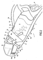
- the palm 1 comprises a footwear portion 2 open at the rear, said footwear portion 2 being delimited at its lateral sides 2b, 2c, as illustrated in FIG. figure 2 .
- the strap 12 has a length greater than that illustrated in FIG. figure 1 so as to extend the end portions 12a, 12b on the back of the foot and preferably to allow attachment of said end portions 12a, 12b in the rear area of the foot, as illustrated in FIG. figure 2 .
- a portion 12c of the strap covers the top of the footwear portion extending from the lateral sides of the bearing portion 3, at the openings 13, while the end portions 12a, 12b of said strap cover the rear of the foot, which ensures both a tightening of the footwear portion around the foot and a nested position of the foot inside said foot portion 2.
- openings 17 are preferably of the passing type; it can however provide the implementation of slot. Moreover, as illustrated in figure 3 , there can be provided an opening 17 of type consisting of two portions 17a, 17b between which is formed a narrow passage 17c facilitating the positioning of the end portions 12a, 12b in said passer on the footwear part 2.
- padding 18 is provided on the strap, in the region of the end portions 12a, 12b which can be fixed together.
- this padding 18 is secured to one of the ends and in particular the end 12b on which are arranged the loops of the fastening means. It can also provide that padding 18 is removable.
- At least one of the lateral sides 2b, 2c comprises an extension 20 positioned behind the foot during the introduction of the strap 12.
- this palm 2 The operation and use of this palm 2 are relatively easy for the user since, to insert his foot in the palm, it suffices to loosen the strap 12 and advance the tongue 10 forward so as to spare the largest free space for the insertion of the foot.
- FIGS. figures 1 and 2 In order to facilitate the movement of the tongue 10, it is provided as shown in FIGS. figures 1 and 2 an enlargement 16 at the ends of the slots 7.
- the user drops the tongue 10 and ensures the tightening around his foot by pulling on the strap 12 and then fixing it at the hook-type fastening means, or on the top of the footwear part 2 in the case illustrated in figure 1 , either on the back of the user's foot in the case illustrated in figure 2 .
- clamping means 9 makes it possible to adjust or readjust the palm even when the user is in the water.
- the end portions 12a, 12b of the strap 12, on which the fastening means 15 are positioned be removable.
Landscapes
- Health & Medical Sciences (AREA)
- General Health & Medical Sciences (AREA)
- Physical Education & Sports Medicine (AREA)
- Footwear And Its Accessory, Manufacturing Method And Apparatuses (AREA)
- Building Environments (AREA)
- Acyclic And Carbocyclic Compounds In Medicinal Compositions (AREA)
Abstract
Description
L'invention concerne une palme notamment destinée à des activités de loisir.The invention relates to a fin particularly intended for leisure activities.
L'invention prendra son application principale dans la réalisation d'une palme avec une partie chaussante ajustable destinée à équiper des individus adultes ou enfants pour des activités nautiques telles que la plongée, la chasse sous-marine, l'apnée, la nage, le body-board ou encore le snorkeling.The invention will take its main application in the realization of a palm with an adjustable footwear intended to equip adults or children for nautical activities such as diving, spearfishing, snorkeling, swimming, swimming. body-board or snorkeling.
Bien que particulièrement prévue pour des applications à titre de loisirs, il sera également envisageable d'utiliser cette palme dans des activités professionnelles diverses et notamment par des pêcheurs ou plongeurs encore dans des activités de sauvetage en mer.Although particularly intended for recreational applications, it will also be possible to use this palm in various professional activities and especially by fishermen or divers still in rescue activities at sea.
Les palmes de natation sont composées essentiellement de deux parties, une partie chaussante et une partie d'appui intégrant une voilure et venant réceptionner la partie chaussante.The swimming fins are composed essentially of two parts, a footwear part and a support part incorporating a wing and receiving the footwear part.
En fonction des différents types de palme, la partie chaussante et la partie d'appui pourront être soit détachables l'une de l'autre, soit fixées solidairement, soit encore complètement intégrées, les deux parties n'en faisant qu'une.Depending on the different types of palm, the footwear and the support part may be either detachable from one another, or fixed integrally, or completely integrated, the two parts being one.
Un inconvénient important des palmes est la difficulté pour l'utilisateur d'insérer son pied dans le chausson compte tenu de l'étroitesse de l'ouverture du chausson et à contrario de maintenir correctement le pied lors de la nage compte tenu des contraintes exercées tendant à faire sortir le pied du chausson si ce dernier n'est pas convenablement serré autour du pied de l'utilisateur.A major disadvantage of the fins is the difficulty for the user to insert his foot in the slipper given the narrowness of the opening of the boot and contrario to maintain the foot correctly when swimming given the constraints exerted tending to remove the foot of the liner if it is not properly tightened around the foot of the user.
Parmi l'ensemble des palmes existantes avec des parties chaussantes réalisées de manière très diverse, il existe un type de partie chaussante particulièrement utilisé pour la pratique de la plongée ; il s'agit d'un chausson assujetti à la partie d'appui et entourant complètement le pied de l'utilisateur à savoir à la fois le talon, la plante du pied et le coup du pied.Among all the existing fins with foot parts made in a very diverse manner, there is a type of footwear particularly used for the practice of diving; it is a slipper subject to the support part and completely surrounding the foot of the user to know both the heel, the sole of the foot and the kick.
Ce type de chausson est réalisé généralement en matière plastique, de préférence un élastomère, et élastique de manière à pouvoir être déformé et à permettre l'insertion du pied de l'utilisateur.This type of liner is generally made of plastic material, preferably an elastomer, and resilient so as to be deformed and allow the insertion of the user's foot.
Ce type de chausson permet à la fois de pouvoir insérer le pied dans le chausson tout en assurant un serrage efficace de ce pied une fois ce dernier inséré ; là étant, ce chausson présente toutefois différents inconvénients et notamment, il est nécessaire pour l'utilisateur de tirer fortement sur les bords de la partie chaussante pour pouvoir insérer le pied.This type of liner allows both to insert the foot into the liner while ensuring effective tightening of the foot once the latter inserted; there being, however, this shoe has various disadvantages and in particular, it is necessary for the user to pull strongly on the edges of the footwear to insert the foot.
D'autre part, bien que ce type de chausson soit prévu pour des utilisateurs avec des cou-de-pied différents, on comprend bien que la compression exercée par la partie chaussante sur le pied n'est pas réglable et par conséquent, une personne ayant un fort cou-de-pied verra son pied fortement comprimé et une personne ayant un faible cou-de-pied pourra voir son pied flotté légèrement dans la partie chaussante.On the other hand, although this type of slipper is provided for users with different instep, it is understood that the compression exerted by the foot part on the foot is not adjustable and therefore a person having a strong instep will have a severely compressed foot and a person with a weak instep will be able to see his / her foot floated slightly in the foot part.
On connaît un autre type de palme tel que celui décrit dans les documents
La présente invention a pour but de pallier aux inconvénients précités et de proposer une palme permettant de réunir en combinaison les caractéristiques techniques suivantes :
- une partie chaussante de conception à la fois robuste et fiable ;
- une partie chaussante adaptable à des tailles de cou-de-pied varié ;
- une partie chaussante permettant une insertion et un retrait rapides et aisés du pied de l'utilisateur ;
- des moyens de serrage permettant de maintenir le pied dans la partie chaussante, empêchant par conséquent tout retrait accidentel du pied hors de la partie chaussante ;
- des moyens de serrage assurant une bonne transmission de l'effort entre la jambe de l'utilisateur et la voilure et ainsi une bonne propulsion de la palme et ;
- des moyens de serrage évitant toute dégradation de la partie chaussante.
- a footwear section of design that is both robust and reliable;
- a footwear portion adaptable to varied instep sizes;
- a footwear portion for quick and easy insertion and removal of the user's foot;
- clamping means for holding the foot in the footwear portion, thereby preventing accidental removal of the foot from the footwear portion;
- clamping means ensuring a good transmission of the force between the leg of the user and the wing and thus a good propulsion of the palm and;
- clamping means avoiding any deterioration of the footwear part.
A cet effet, la présente invention concerne une palme comportant une partie chaussante souple, une partie d'appui rigide, ladite partie d'appui intégrant une voilure et une zone de réception de la partie chaussante et des moyens de liaison entre les parties chaussante pour assujettir entre elles lesdites parties ; par ailleurs, la partie chaussante comporte sur sa face supérieure au moins une fente s'étendant partiellement sur la longueur de la partie chaussante. Cela présente pour avantage de faciliter l'introduction du pied dans la partie chaussante ou, au contraire, son retrait. En outre, des moyens de serrage sont agencés entre la partie chaussante et la partie d'appui pour au moins prendre appui, de manière directe ou indirecte, sur les côtés latéraux de ladite partie d'appui, assujettie à la partie chaussante, et exercer une pression sur la face supérieure de ladite partie chaussante lors du serrage, en sorte d'assurer le resserrage de la fente sur ladite partie chaussante. Cette conception présente pour avantage que les moyens de serrage prennent appui sur les côtés latéraux de la partie d'appui relativement rigide et non sur la partie chaussante relativement souple, ce qui permet lors de la mise en place desdits moyens de serrage, d'éviter toute déformation de la partie chaussante et, en outre, de permettre auxdits moyens de serrage assujettis à la partie d'appui rigide, d'exercer leur fonction de pression sur le dessus de la partie chaussante, c'est-à-dire le contour supérieur de la partie chaussante s'étendant depuis les côtés latéraux de la partie d'appui rigide, zone dans laquelle se situe la fente. On assure ainsi le resserrage de cette fente et, par conséquent, le resserrage de la partie chaussante autour du pied de l'utilisateur.For this purpose, the present invention relates to a fin comprising a flexible footwear part, a rigid support part, said support part incorporating a wing and a receiving area of the footwear part and connecting means between the footwear parts for subject the said parts to each other; in addition, the footwear portion has on its upper face at least one slot extending partially along the length of the footwear part. This has the advantage of facilitating the introduction of the foot in the footwear or, on the contrary, its withdrawal. In addition, clamping means are arranged between the footwear portion and the support portion to at least bear, directly or indirectly, on the lateral sides of said support portion, secured to the footwear portion, and exercise a pressure on the upper face of said foot portion during tightening, so as to ensure the tightening of the slot on said footwear. This design has the advantage that the clamping means bear on the lateral sides of the relatively rigid support part and not on the relatively soft footwear part, which allows during the establishment of said clamping means, to avoid any deformation of the footwear part and, furthermore, to allow said clamping means subject to the rigid support portion, d ' exert their pressure function on the top of the footwear portion, that is to say the upper contour of the footwear portion extending from the lateral sides of the rigid support portion, zone in which the slot is located. This ensures the tightening of this slot and, therefore, the tightening of the footwear around the foot of the user.
En outre, cette conception présente pour avantage de prendre appui sur les côtés latéraux de la partie d'appui rigide tout en conservant convenablement le pied dans l'axe de la voilure.In addition, this design has the advantage of being supported on the lateral sides of the rigid support portion while properly keeping the foot in the axis of the wing.
Par ailleurs, la mise en place des moyens de serrage prenant appui sur les côtés latéraux de la partie d'appui permet de renforcer la stabilité de ladite partie d'appui par rapport au pied du nageur ce qui assure une bonne transmission de l'effort entre la jambe de l'utilisateur et la voilure, et ainsi permet une bonne propulsion de la palme.Furthermore, the establishment of the clamping means bearing on the lateral sides of the support portion reinforces the stability of said support portion relative to the swimmer's foot which ensures a good transmission of the effort between the user's leg and the wing, and thus allows a good propulsion of the palm.
On entend par partie chaussante souple et partie d'appui rigide le fait que ladite partie d'appui comprend une rigidité relativement importante par rapport à la partie chaussante en sorte que cette partie d'appui assure une bonne transmission de l'effort entre la jambe de l'utilisateur et la voilure et que cette partie chaussante assure au contraire une bonne déformation pour faciliter l'introduction du pied à l'intérieur de la partie chaussante puis, en vue d'optimiser le confort, épouser convenablement le contour du pied lors de la mise en place des moyens de serrage.The term "soft footwear" and "rigid support portion" means that said support portion comprises a relatively high rigidity relative to the footwear portion, so that this support portion ensures good transmission of the force between the leg. of the user and the wing and that this footwear ensures on the contrary a good deformation to facilitate the introduction of the foot inside the footwear part and, in order to maximize comfort, properly marry the outline of the foot when setting up the clamping means.
Selon l'invention, les moyens de serrage comportent une sangle assujettie aux côtés latéraux de la partie d'appui et dont au moins une portion est disposée au dessus de la face supérieure de la partie chaussante, c'est-à-dire le contour supérieur s'étendant depuis lesdits côtés latéraux de la partie d'appui. Cette sangle traverse une ouverture ménagée sur une pièce d'appui rigide agencée sur au moins l'un des côtés latéraux de la palme, ladite pièce d'appui rigide étant assujettie de manière directe ou indirecte à la partie d'appui et à la partie chaussante. En outre, des moyens de fixation sont agencés sur la sangle pour maintenir, une fois la sangle serrée et lesdits moyens de fixation mis en place, au moins ladite portion de sangle pressée sur le dessus de ladite face supérieure. De telles caractéristiques présentent pour avantage de faciliter le serrage et le desserrage de la sangle pour insérer ou retirer le pied tout en conservant en position ladite sangle.According to the invention, the clamping means comprise a strap secured to the lateral sides of the bearing portion and at least a portion of which is disposed above the upper face of the foot part, that is to say the contour upper extending from said lateral sides of the support portion. This strap passes through an opening formed on a rigid support piece arranged on at least one of the lateral sides of the fin, said rigid support piece being attached directly or indirectly to the support part and to the part full foot. In addition, fixing means are arranged on the strap to maintain, once the strap tight and said fastening means in place, at least said webbing portion pressed on top of said upper face. Such features have the advantage of facilitating the tightening and loosening of the strap to insert or remove the foot while maintaining in position said strap.
Diverses conception de la pièce d'appui rigide sont envisageables ; on peut prévoir que cette pièce d'appui rigide soit indépendante de la partie d'appui et de la partie chaussante tout en étant assujettie aux dites parties. On peut également prévoir que cette pièce d'appui soit une partie rigide intégrée sur le ou les côtés latéraux de la partie d'appui, ladite partie d'appui et la partie chaussante étant assujetties entre elles. On peut au contraire prévoir que la pièce d'appui soit une partie rigide intégrée sur le ou les côtés latéraux de la partie chaussante souple, ladite partie rigide sur le ou les côtés latéraux de la partie chaussante étant assujettie à la partie d'appui.Various designs of the rigid support piece are conceivable; it can be expected that the rigid support piece is independent of the support portion and the footwear while being subject to said parts. It is also possible that this support piece is a rigid portion integrated on the lateral side or sides of the support portion, said support portion and the foot portion being secured together. On the contrary, it is possible for the support piece to be a rigid part integrated on the lateral side or sides of the flexible footwear part, the rigid part on the lateral side or sides of the footwear part being fastened to the support part.
Selon une caractéristique avantageuse de l'invention, une pièce rigide munie d'une ouverture est agencée de chaque côté latéral de la palme, la sangle traversant lesdites ouvertures sur lesdits côtés latéraux. Cela permet d'une part de faciliter le desserrage de la sangle pour l'insertion ou le retrait du pied, vis-à-vis de la partie chaussante et, d'autre part, de permettre le dégagement complet de la sangle, par exemple pour effectuer son remplacement en cas de détérioration, ladite sangle étant soumise à des efforts de traction lors de la mise en place des moyens de serrage.According to an advantageous characteristic of the invention, a rigid piece provided with an opening is arranged on each lateral side of the fin, the strap passing through said openings on said lateral sides. This allows on the one hand to facilitate the loosening of the strap for the insertion or removal of the foot, vis-à-vis the footwear and, secondly, to allow the complete release of the strap, for example to perform its replacement in case of deterioration, said strap being subjected to tensile forces during the establishment of the clamping means.
Par ailleurs, l'ouverture sur les côtés latéraux de la partie d'appui est notamment constituée d'un passant ou d'une fente en sorte de permettre le positionnement de la sangle vis-à-vis de la partie d'appui.Furthermore, the opening on the lateral sides of the support portion is in particular constituted by a passer or slot so as to allow positioning of the strap vis-à-vis the support portion.
On entend par « direct » et « indirect », au sens de l'invention, respectivement le fait que, d'une part, les moyens de serrage prennent appui directement sur les côtés latéraux de la partie d'appui et que, d'autre part, ces moyens de serrage prennent appui indirectement sur les côtés latéraux de la partie d'appui par le biais de pièces d'appui rigides intermédiaires, assujetties auxdits côtés latéraux de la partie d'appui, ce qui dans les deux cas évite toute déformation de la partie chaussante et permet auxdits moyens de serrage assujettis à la partie d'appui rigide, directement ou indirectement, d'exercer la fonction de pression sur le dessus de la partie chaussante sans déformer celle-ci.For the purposes of the invention, the term "direct" and "indirect" means, respectively, that, on the one hand, the clamping means bear directly on the lateral sides of the support part and that, on the other hand, these clamping means bear indirectly on the lateral sides of the support part by means of intermediate rigid support pieces, secured to said lateral sides of the support part, which in both cases avoids any deformation of the footwear portion and allows said clamping means subject to the rigid bearing portion, directly or indirectly, to exert the pressure function on the top of the footwear without distorting it.
Selon l'invention, la partie d'appui comprend deux bras latéraux qui s'étendent de la voilure vers l'arrière de la palme sur les côtés latéraux. En outre, la sangle est assujettie auxdits bras latéraux, une ouverture étant ménagée au niveau d'au moins l'un desdits bras latéraux de la partie d'appui pour le passage de la sangle. Dans ce cas, le bras latéral constitue la pièce d'appui rigide. De tels bras latéraux permettent de déporter la voilure par rapport à la partie chaussante. La position des ouvertures sur les bras latéraux présente en outre pour avantage, d'une part, d'améliorer le positionnement de la sangle vis-à-vis de la face supérieure de la partie chaussante et, d'autre part, d'accroître la stabilité de la partie d'appui supportant la voilure vis-à-vis du pied, lors d'efforts transmis durant la nage.According to the invention, the support portion comprises two lateral arms which extend from the wing towards the rear of the fin on the lateral sides. In addition, the strap is secured to said side arms, an opening being provided at at least one of said side arms of the support portion for the passage of the strap. In this case, the lateral arm constitutes the rigid support piece. Such side arms can deport the wing relative to the footwear. The position of the openings on the lateral arms also has the advantage, on the one hand, to improve the positioning of the strap vis-à-vis the upper face of the foot part and, on the other hand, to increase the stability of the support part supporting the wing vis-à-vis the foot, during efforts transmitted during swimming.
Selon une autre caractéristique de l'invention, les moyens de fixation sont du type mâle et femelle et sont agencés respectivement dans les deux parties d'extrémité de la sangle. De manière préférentielle, ces moyens de fixation sont du type de boucle crochet, ce qui présente pour avantage d'obtenir un serrage précis et réajustable rapidement notamment lorsque l'utilisateur est dans l'eau.According to another characteristic of the invention, the fixing means are of the male and female type and are respectively arranged in the two end portions of the strap. Preferably, these fastening means are of the hook loop type, which has the advantage of obtaining a precise tightening and quickly readjustable especially when the user is in the water.
Cette caractéristique permet également de réaliser des moyens de serrage de conception relativement simple et permet en outre d'adapter la force du serrage à la taille au cou-de-pied de l'utilisateur.This characteristic also makes it possible to produce clamping means of relatively simple design and also makes it possible to adapt the force of the clamping to the size at the instep of the user.
Bien entendu, d'autres moyens de fixation sont envisageables, tels qu'un système de bouclage ou d'encliquetage de type mâle/femelle.Of course, other fastening means are conceivable, such as a buckling or snap-fastening system of the male / female type.
Selon l'invention, la partie chaussante est soit ouverte ou fermée à l'arrière. En outre, la longueur de la sangle est adaptée selon le cas où la partie chaussante est ouverte ou fermée. Lorsque la partie chaussante est fermée à l'arrière, la longueur de la sangle est agencée en sorte que les deux parties d'extrémité de ladite sangle soient fixées entre elles sur le dessus de la face supérieure de la partie chaussante et que ladite sangle exerce une pression sur ladite face supérieure, c'est-à-dire sur le contour supérieur de la partie chaussante s'étendant depuis les côtés latéraux de la partie d'appui assujettie à ladite sangle. Au contraire, lorsque la partie chaussante est ouverte sur l'arrière, la longueur de la sangle est agencée en sorte que les deux parties d'extrémité soient fixées entre elles sur l'arrière du pied, dans la zone ouverte de préférence, et que la sangle assure une pression sur la face supérieure de la partie chaussante et une pression sur l'arrière du pied pour le maintien de celui-ci emboité dans ladite partie chaussante. La conception selon ces deux modes de réalisation présente pour avantage de faciliter la mise en place ou le retrait des moyens de serrage pour l'insertion ou le retrait du pied, tout en facilitant le maintien en position de la sangle vis-à-vis de la partie chaussante et de la partie d'appui.According to the invention, the footwear portion is either open or closed at the rear. In addition, the length of the strap is adapted to the case where the footwear is open or closed. When the footwear is closed at the rear, the length of the strap is arranged so that the two end portions of said strap are fixed together on the top of the upper face of the footwear and that said strap exerts a pressure on said upper face, that is to say on the upper contour of the footwear portion extending from the lateral sides of the support portion secured to said strap. On the contrary, when the footwear is open at the rear, the length of the strap is arranged so that the two end portions are fixed together on the back of the foot, in the open area preferably, and that the strap provides pressure on the upper face of the footwear and a pressure on the back of the foot to maintain it encased in said footwear. The design according to these two embodiments has the advantage of facilitating the introduction or removal of clamping means for the insertion or removal of the foot, while facilitating the maintaining the strap in position vis-à-vis the footwear portion and the support portion.
Lorsque la partie chaussante est ouverte sur l'arrière, celle-ci présente, sur au moins un côté latéral, et de préférence de chaque côté latéral, une ouverture, cette ouverture assurant le passage des portions d'extrémité de la sangle et le serrage de ladite sangle contre les côtés latéraux de la partie chaussante. Cela présente pour avantage d'assurer le maintien convenable de la sangle vis-à-vis des côtés latéraux de la partie chaussante ouverte, en sorte de faciliter le positionnement de la sangle sur l'arrière du pied ainsi que le positionnement convenable de la sangle vis-à-vis de la partie chaussante. Cette ouverture peut être conçue de différentes manières ; celle-ci est par exemple constituée d'un passant ou d'une fente permettant tous les deux le passage coulissant de la sangle par rapport à la partie chaussante et le maintient en position entre lesdits éléments.When the footwear portion is open at the rear, it has, on at least one lateral side, and preferably on each lateral side, an opening, this opening ensuring the passage of the end portions of the strap and the tightening of said strap against the lateral sides of the footwear part. This has the advantage of ensuring the proper retention of the strap vis-à-vis the lateral sides of the open footwear, so as to facilitate the positioning of the strap on the back of the foot and the proper positioning of the strap vis-à-vis the footwear. This opening can be conceived in different ways; this is for example constituted by a passer or slot allowing both the sliding passage of the strap relative to the footwear portion and holds it in position between said elements.
Selon l'invention, les moyens de serrage comportent au moins un passant disposé sur la partie chaussante et assurant le serrage de la partie chaussante.According to the invention, the clamping means comprise at least one passer arranged on the footwear part and ensuring the tightening of the footwear part.
Cette caractéristique permet de bien positionner les moyens de serrage vis-à-vis de la partie chaussante, même lorsque ces derniers sont desserrés pour permettre l'insertion ou le retrait du pied de l'utilisateur.This feature allows to properly position the clamping means vis-à-vis the footwear part, even when they are loosened to allow the insertion or withdrawal of the foot of the user.
Selon une autre caractéristique avantageuse de l'invention, la partie chaussante comporte deux fentes permettant la formation d'une languette.According to another advantageous characteristic of the invention, the footwear part comprises two slots allowing the formation of a tongue.
Cette caractéristique permet de faciliter l'insertion du pied de l'utilisateur en présentant une grande surface d'ouverture lorsque la languette est avancée en direction de l'avant de la partie chaussante.This feature facilitates the insertion of the foot of the user with a large opening surface when the tongue is advanced towards the front of the footwear.
Cette caractéristique permet de réaliser des moyens de serrage de conception relativement simple et permet en outre d'adapter la force du serrage à la taille au cou-de-pied de l'utilisateur.This feature allows for clamping means of relatively simple design and further allows to adapt the clamping force to the waist to the instep of the user.
Selon une autre caractéristique de l'invention, la languette et la partie chaussante sont formées d'une seule pièce.According to another characteristic of the invention, the tongue and the foot part are formed in one piece.
Cette caractéristique permet à la fois de faciliter les opérations de fabrication de la partie chaussante et par ailleurs, confère une résistance importante à l'ensemble.This feature makes it possible both to facilitate the manufacturing operations of the footwear and, moreover, confers a significant resistance to the assembly.
Selon une autre caractéristique avantageuse de l'invention, ladite au moins une fente présente un élargissement au niveau de son extrémité fermée de manière à renforcer la résistance à l'arrachement de la languette avec la partie chaussante.According to another advantageous characteristic of the invention, said at least one slot has a widening at its closed end so as to reinforce the tear resistance of the tongue with the footwear part.
Bien entendu, d'autres caractéristiques et avantages de l'invention apparaîtront plus clairement au cours de la description ci-après des deux modes préférés de réalisation dans lesquels la description n'est donnée qu'à titre d'exemple non limitatif et en référence aux dessins ci-annexés, à savoir :
- la
figure 1 représentant un exemple en perspective d'une partie de la palme conforme à l'invention selon laquelle la partie chaussante est fermée sur l'arrière ; - la
figure 2 représentant un exemple en perspective d'une partie de la palme conforme à l'invention selon laquelle la partie chaussante est ouverte sur l'arrière ; - la
figure 3 représente une variante selon lafigure 2 .
- the
figure 1 showing an example in perspective of a portion of the palm according to the invention according to which the footwear is closed on the rear; - the
figure 2 showing a perspective example of a portion of the fin according to the invention according to which the footwear portion is open at the rear; - the
figure 3 represents a variant according to thefigure 2 .
En se reportant aux
Cette partie d'appui 3 comporte une voilure 4 partiellement représentée dans les dessins des
La partie d'appui 3 comporte également une zone de réception 5 de la partie chaussante et des moyens de liaison 6 entre les parties chaussante 2 et d'appui 3, lesdits moyens de liaison permettant d'assujettir entre elles la partie chaussante 2 et la partie d'appui 3.The bearing portion 3 also comprises a receiving
Selon un premier mode de réalisation concevable pour les palmes illustrées aux
Toutefois, selon d'autres modes de réalisation, il est envisageable d'avoir une partie chaussante 2 séparable de la partie d'appui 3, l'assujettissement pouvant s'effectuer notamment à l'aide de moyens de liaison 6 réalisés entre les côtés latéraux de la partie chaussante 2 et de la partie d'appui 3, voire également au niveau de l'extrémité avant de ladite partie chaussante. On peut par exemple prévoir que la partie d'appui soit constituée de deux parties rigides, l'une 31 assujettie par surmoulage à la partie chaussante 2 et l'autre 32 assujettie à la première partie 31 par une liaison pivotante amovible, d'axe transversal, telle qu'illustrée en
Selon l'invention, la partie chaussante 2 comporte, sur sa face supérieure 8, au moins une fente 7 s'étendant partiellement sur la longueur de la partie chaussante 2.According to the invention, the
Dans les exemples de réalisation des
On voit également que des moyens de serrage 9 sont mis en oeuvre au moins sur le dessus de la partie chaussante 2 et permettent d'effectuer le serrage de ladite partie chaussante autour du pied de l'utilisateur.It is also seen that clamping means 9 are implemented at least on the top of the
Comme représenté sur les
On voit représenté un seul passant 11 disposé sur la partie chaussante 2 et permettant de venir recevoir la sangle 12 apte à assurer le serrage de la partie chaussante.There is shown a
Dans d'autres modes de réalisation, on pourra prévoir plusieurs passants 11 afin d'assurer un bon maintien de la sangle 12.In other embodiments, it will be possible to provide
Tel qu'illustré aux
Par ailleurs, ces bras 14 latéraux s'étendent de la voilure vers l'arrière de la palme 1, sur les côtés latéraux 3a,3b de la partie d'appui 3.Moreover, these
Selon la variante illustrée en
D'autres positions de l'ouverture 13 sur la partie d'appui 3 peuvent toutefois être envisagées notamment lorsque cette partie d'appui présente une conception différente, non équipée de tels bras latéraux 14. En outre, on peut également prévoir, notamment pour la palme illustrée en
Par ailleurs, on voit sur les
On voit également qu'avantageusement, la sangle 12 comporte, dans ses parties d'extrémité 12a, 12b, des moyens de fixation 15 de type boucle crochet. On peut toutefois prévoir un système mâle/femelle d'encliquetage.We also see that advantageously, the
Selon le mode de réalisation illustré en
Selon la variante de réalisation illustrée en
Ces ouvertures 17 sont de préférence du type passant ; on peut toutefois prévoir la mise en oeuvre de fente. Par ailleurs, tel qu'illustré en
Selon le mode illustré en
Selon le mode illustré en
Le fonctionnement et l'utilisation de cette palme 2 sont relativement aisés pour l'utilisateur puisque, pour insérer son pied dans la palme, il lui suffit de desserrer la sangle 12 puis d'avancer la languette 10 vers l'avant de manière à ménager l'espace libre le plus large possible pour l'insertion du pied.The operation and use of this
De manière à faciliter le déplacement de la languette 10, on prévoit tel que représenté aux
Une fois le pied inséré, l'utilisateur laisse retomber la languette 10 et vient assurer le serrage autour de son pied en tirant sur la sangle 12 puis en la fixant au niveau des moyens de fixation de type boucle crochet, soit sur le dessus de la partie chaussante 2 dans le cas illustré en
A ce sujet, il est représenté sur les
Il est intéressant de noter que le fonctionnement relativement simple des moyens de serrage 9 permet d'ajuster ou de réajuster la palme même lorsque l'utilisateur se trouve dans l'eau.It is interesting to note that the relatively simple operation of the clamping means 9 makes it possible to adjust or readjust the palm even when the user is in the water.
Par ailleurs, pour éviter le changement total de la sangle 12 en cas d'usure des moyens de fixation 15, on prévoit avantageusement que les parties d'extrémité 12a,12b de la sangle 12, sur lesquelles sont positionnés les moyens de fixation 15, soient amovibles.Moreover, to avoid the total change of the
Bien entendu, d'autres modes de réalisation à la portée de l'homme de l'art auraient également pu être envisagés sans pour autant sortir du cadre de l'invention définie par les revendications ci-après.Of course, other embodiments within the reach of those skilled in the art could also be envisaged without departing from the scope of the invention defined by the claims below.
Notamment, il est tout à fait envisageable de réaliser une partie chaussante 2 avec une seule fente 7 ou encore une multitude de fentes 7.In particular, it is quite possible to make a
On peut également envisager différentes localisations pour le passant 11 et notamment sur les parties latérales de la partie chaussante 2.We can also consider different locations for the
Claims (20)
- A fin (1) comprising a flexible footwear portion (2), a rigid bearing portion (3), said bearing portion incorporating a web (4) and a receiver zone (5) for receiving the footwear portion, and connection means (6) between the footwear and bearing portions (2, 3), the footwear portion (2) including at least one slot (7) in its top face (8), the slot extending over part of the length of the footwear portion, the fin being characterized in that tightening means (9) are arranged between the footwear portion and the bearing portion at least to bear, directly or indirectly, against the lateral sides (3a, 3b) of said bearing portion (3) and to exert pressure on the top face (8) of said footwear portion on being tightened so as to narrow the slot in the footwear portion.
- A fin (1) according to claim 1, wherein the tightening means (9) comprise a strap (12) secured to the lateral sides (3a, 3b) of the bearing portion (3), the strap including at least a portion (12c) that is located above the top face (8) of the footwear portion (2), said strap passing through an opening (13) formed in a rigid part (19, 14) arranged on at least one of the lateral sides of the fin, said part being secured directly or indirectly to the bearing portion (3) and to said footwear portion, fastener means (15) being arranged on said strap to hold at least said portion (12c) pressed against the top of said top face (8).
- A fin (1) according to claim 2, wherein a rigid part (19, 14) having an opening (13) is arranged on each lateral side (3a, 3b) of the fin, the strap (12) passing through said openings in said lateral sides.
- A fin (1) according to claim 2 or claim 3, wherein the bearing portion (3) has two lateral arms (14), the strap (12) being secured to said lateral arms, an opening (13) being formed through at least one of said lateral arms (14) of the bearing portion.
- A fin (1) according to claim 2 or claim 3, wherein the bearing portion (3) has two rigid lateral extensions (19), the strap (12) being secured to said extensions (19), an opening (13) being formed in at least one of said extensions (19).
- A fin (1) according to any one of claims 2 to 5, wherein the fastener means (15) are of the male and female type, being arranged respectively in the two end portions (12a, 12b) of the strap (12).
- A fin (1) according to claim 6, wherein the fastener means (15) are of the loop-and-hook type.
- A fin (1) according to claim 6, wherein the fastener means are of the male/female snap-fastening system type.
- A fin (1) according to any one of claims 6 to 8, wherein the fastener means (15) are removable.
- A fin (1) according to any one of claims 6 to 9, wherein the footwear portion (2) is closed at the heel (2a), the length of the strip (12) being arranged so that the two end portions (12a, 12b) of said strap are fastened together over the top face (8) of the footwear portion and said strap exerts pressure on said top face.
- A fin (1) according to any one of claims 6 to 9, wherein the footwear portion (2) is open at the heel, the length of the strap (12) being arranged so that the two end portions (12a, 12b) are fastened together over the heel of the foot and the strap exerts pressure against the top face of the footwear portion and pressure against the heel of the foot so as to hold said foot engaged in said footwear portion.
- A fin (1) according to claim 11, wherein the footwear portion includes in each of its two lateral sides (2b, 2c) at least one opening (17) for passing the end portions (12a, 12b) of the strap (12) and for tightening the strap against said lateral sides (2b, 2c) of the footwear portion.
- A fin (1) according to claim 11 or claim 12, wherein the strap (12) includes padding (18).
- A fin (1) according to claim 12, wherein at least one of the lateral sides (2b, 2c) of the footwear portion (2) includes an extension (20).
- A fin (1) according to claim 12, wherein the opening (17) is of the through type and is constituted by two portions (17a, 17b) having a passage (17c) formed between them for positioning the end portions (12a, 12b) of the strap (12).
- A fin (1) according to any one of claims 2 to 15, wherein the tightening means (9) include at least one keeper (11) located on the footwear portion (2) and serving to tighten the footwear portion, the strap (12) passing through said at least one keeper.
- A fin (1) according to claim 16, wherein the at least one keeper (11) is associated with the top face of the footwear portion.
- A fin (1) according to any one of claims 1 to 17, wherein the footwear portion (2) includes two slots (7) enabling a tongue (10) to be formed.
- A fin (1) according to claim 18, wherein the tongue (10) and the footwear portion (2) are formed as a single piece.
- A swim fin according to any one of claims 1 to 19, wherein said at least one slot (7) presents a widening (16) at its closed end.
Applications Claiming Priority (2)
| Application Number | Priority Date | Filing Date | Title |
|---|---|---|---|
| FR0850589A FR2926999B1 (en) | 2008-01-31 | 2008-01-31 | PALM OF SWIM |
| FR0950168A FR2940917B1 (en) | 2009-01-14 | 2009-01-14 | WEBBED |
Publications (2)
| Publication Number | Publication Date |
|---|---|
| EP2085122A1 EP2085122A1 (en) | 2009-08-05 |
| EP2085122B1 true EP2085122B1 (en) | 2011-03-23 |
Family
ID=40670950
Family Applications (1)
| Application Number | Title | Priority Date | Filing Date |
|---|---|---|---|
| EP09150750A Active EP2085122B1 (en) | 2008-01-31 | 2009-01-16 | Swim fin |
Country Status (3)
| Country | Link |
|---|---|
| EP (1) | EP2085122B1 (en) |
| AT (1) | ATE502684T1 (en) |
| DE (1) | DE602009000923D1 (en) |
Families Citing this family (1)
| Publication number | Priority date | Publication date | Assignee | Title |
|---|---|---|---|---|
| CN104338292A (en) * | 2014-11-18 | 2015-02-11 | 曹伟 | Underwater bionic swimming aid sock shoes |
Family Cites Families (4)
| Publication number | Priority date | Publication date | Assignee | Title |
|---|---|---|---|---|
| FR1190346A (en) | 1958-01-22 | 1959-10-12 | Swimming shoe | |
| US5266062A (en) * | 1992-07-28 | 1993-11-30 | John L. Runckel Trust | Amphibious footwear |
| IT1285634B1 (en) | 1996-03-22 | 1998-06-18 | Pio Maria Guglielmo Curatolo | AMPHIBIAN FOOTWEAR |
| US6663452B1 (en) | 2002-10-22 | 2003-12-16 | Robert J. Myers | Aquatic fins |
-
2009
- 2009-01-16 AT AT09150750T patent/ATE502684T1/en not_active IP Right Cessation
- 2009-01-16 DE DE602009000923T patent/DE602009000923D1/en active Active
- 2009-01-16 EP EP09150750A patent/EP2085122B1/en active Active
Also Published As
| Publication number | Publication date |
|---|---|
| ATE502684T1 (en) | 2011-04-15 |
| EP2085122A1 (en) | 2009-08-05 |
| DE602009000923D1 (en) | 2011-05-05 |
Similar Documents
| Publication | Publication Date | Title |
|---|---|---|
| EP1112697B1 (en) | High upper shoe with lacing fastening | |
| EP0826318B2 (en) | Sportsshoe with returning means which are supple and resistant to traction | |
| WO2014033396A1 (en) | Articulated shoe having automatic tightening | |
| FR2914542A1 (en) | FOOTWEAR, IN PARTICULAR SPORT OR LEISURE | |
| FR2872389A1 (en) | FOOTWEAR ARTICLE AND LACE SYSTEM FOR SUCH A ARTICLE | |
| EP1712147B1 (en) | Easy entry sports shoe | |
| WO2012031801A1 (en) | Sandal and corresponding manufacturing method | |
| EP0916273B1 (en) | Skiboot | |
| EP2100644B1 (en) | Swimming flipper adjustable according to the foot's size | |
| FR2827486A1 (en) | Sports shoe is fastened by lace fixed at one end to one side of upper, passed around tag on opposite side of upper and back through second tag on first | |
| EP2085122B1 (en) | Swim fin | |
| EP1555050B1 (en) | Improvement on a strap retainer or similar for fixing shoe to a sport article | |
| FR2953731A1 (en) | PIVOTING SAIL PALM EQUIPPED WITH A STOP SYSTEM | |
| FR2926999A1 (en) | Swim fin for use by e.g. diver during sea-rescue activity, has tightening units supporting sides of support part, and exerting pressure on upper surface of foot-receiving part during tightening to retighten slit of foot-receiving part | |
| FR2736514A1 (en) | SNOW SURF BOOT COMPRISING AN INTERNAL SHELL AND A RIGID ARTICULATED BACK PART | |
| EP1327467A1 (en) | Device for retaining a shoe to a sporting article | |
| FR2940917A1 (en) | Swim fin for use by e.g. diver during sea-rescue activity, has tightening units supporting sides of support part, and exerting pressure on upper surface of foot-receiving part during tightening to retighten slit of foot-receiving part | |
| EP2324889B1 (en) | Flipper provided with an asymmetrically bending blade | |
| EP2213342B1 (en) | Strapping system for retaining a boot on a sports equipment | |
| EP3491955B1 (en) | Fastening device for sport shoe | |
| FR2903914A1 (en) | Footwear receiving device for use on snowshoe, has lateral walls connected to each other by upper wall, and rear retention unit connected to extension of lateral walls, where retention unit has strap cooperating with clip | |
| EP2382886B1 (en) | boot for the practice of alpine skiing | |
| FR2819196A3 (en) | Binding, in particular to be used for snowboard, comprising facility for anatomically correct adjustment of strap to shoe | |
| WO2004077978A1 (en) | Shoe with rapid closure, ice skate comprising such a shoe and rapid closure device for said shoe | |
| EP2431082B1 (en) | Snow shoe binding |
Legal Events
| Date | Code | Title | Description |
|---|---|---|---|
| PUAI | Public reference made under article 153(3) epc to a published international application that has entered the european phase |
Free format text: ORIGINAL CODE: 0009012 |
|
| AK | Designated contracting states |
Kind code of ref document: A1 Designated state(s): AT BE BG CH CY CZ DE DK EE ES FI FR GB GR HR HU IE IS IT LI LT LU LV MC MK MT NL NO PL PT RO SE SI SK TR |
|
| AX | Request for extension of the european patent |
Extension state: AL BA RS |
|
| RIN1 | Information on inventor provided before grant (corrected) |
Inventor name: GUILLOT, FREDERIC Inventor name: SEYNHAVE, JEAN MARC |
|
| 17P | Request for examination filed |
Effective date: 20090911 |
|
| 17Q | First examination report despatched |
Effective date: 20090928 |
|
| AKX | Designation fees paid |
Designated state(s): AT BE BG CH CY CZ DE DK EE ES FI FR GB GR HR HU IE IS IT LI LT LU LV MC MK MT NL NO PL PT RO SE SI SK TR |
|
| GRAP | Despatch of communication of intention to grant a patent |
Free format text: ORIGINAL CODE: EPIDOSNIGR1 |
|
| RIC1 | Information provided on ipc code assigned before grant |
Ipc: A63B 31/11 20060101AFI20101111BHEP |
|
| GRAS | Grant fee paid |
Free format text: ORIGINAL CODE: EPIDOSNIGR3 |
|
| GRAA | (expected) grant |
Free format text: ORIGINAL CODE: 0009210 |
|
| STAA | Information on the status of an ep patent application or granted ep patent |
Free format text: STATUS: THE PATENT HAS BEEN GRANTED |
|
| AK | Designated contracting states |
Kind code of ref document: B1 Designated state(s): AT BE BG CH CY CZ DE DK EE ES FI FR GB GR HR HU IE IS IT LI LT LU LV MC MK MT NL NO PL PT RO SE SI SK TR |
|
| REG | Reference to a national code |
Ref country code: GB Ref legal event code: FG4D Free format text: NOT ENGLISH |
|
| REG | Reference to a national code |
Ref country code: CH Ref legal event code: EP |
|
| REG | Reference to a national code |
Ref country code: IE Ref legal event code: FG4D |
|
| REF | Corresponds to: |
Ref document number: 602009000923 Country of ref document: DE Date of ref document: 20110505 Kind code of ref document: P |
|
| REG | Reference to a national code |
Ref country code: DE Ref legal event code: R096 Ref document number: 602009000923 Country of ref document: DE Effective date: 20110505 |
|
| REG | Reference to a national code |
Ref country code: ES Ref legal event code: FG2A Ref document number: 2362830 Country of ref document: ES Kind code of ref document: T3 Effective date: 20110713 |
|
| REG | Reference to a national code |
Ref country code: NL Ref legal event code: VDEP Effective date: 20110323 |
|
| PG25 | Lapsed in a contracting state [announced via postgrant information from national office to epo] |
Ref country code: GR Free format text: LAPSE BECAUSE OF FAILURE TO SUBMIT A TRANSLATION OF THE DESCRIPTION OR TO PAY THE FEE WITHIN THE PRESCRIBED TIME-LIMIT Effective date: 20110624 Ref country code: LV Free format text: LAPSE BECAUSE OF FAILURE TO SUBMIT A TRANSLATION OF THE DESCRIPTION OR TO PAY THE FEE WITHIN THE PRESCRIBED TIME-LIMIT Effective date: 20110323 Ref country code: SE Free format text: LAPSE BECAUSE OF FAILURE TO SUBMIT A TRANSLATION OF THE DESCRIPTION OR TO PAY THE FEE WITHIN THE PRESCRIBED TIME-LIMIT Effective date: 20110323 Ref country code: LT Free format text: LAPSE BECAUSE OF FAILURE TO SUBMIT A TRANSLATION OF THE DESCRIPTION OR TO PAY THE FEE WITHIN THE PRESCRIBED TIME-LIMIT Effective date: 20110323 Ref country code: HR Free format text: LAPSE BECAUSE OF FAILURE TO SUBMIT A TRANSLATION OF THE DESCRIPTION OR TO PAY THE FEE WITHIN THE PRESCRIBED TIME-LIMIT Effective date: 20110323 |
|
| LTIE | Lt: invalidation of european patent or patent extension |
Effective date: 20110323 |
|
| PG25 | Lapsed in a contracting state [announced via postgrant information from national office to epo] |
Ref country code: AT Free format text: LAPSE BECAUSE OF FAILURE TO SUBMIT A TRANSLATION OF THE DESCRIPTION OR TO PAY THE FEE WITHIN THE PRESCRIBED TIME-LIMIT Effective date: 20110323 Ref country code: SI Free format text: LAPSE BECAUSE OF FAILURE TO SUBMIT A TRANSLATION OF THE DESCRIPTION OR TO PAY THE FEE WITHIN THE PRESCRIBED TIME-LIMIT Effective date: 20110323 Ref country code: FI Free format text: LAPSE BECAUSE OF FAILURE TO SUBMIT A TRANSLATION OF THE DESCRIPTION OR TO PAY THE FEE WITHIN THE PRESCRIBED TIME-LIMIT Effective date: 20110323 Ref country code: CY Free format text: LAPSE BECAUSE OF FAILURE TO SUBMIT A TRANSLATION OF THE DESCRIPTION OR TO PAY THE FEE WITHIN THE PRESCRIBED TIME-LIMIT Effective date: 20110323 Ref country code: BG Free format text: LAPSE BECAUSE OF FAILURE TO SUBMIT A TRANSLATION OF THE DESCRIPTION OR TO PAY THE FEE WITHIN THE PRESCRIBED TIME-LIMIT Effective date: 20110623 Ref country code: NO Free format text: LAPSE BECAUSE OF FAILURE TO SUBMIT A TRANSLATION OF THE DESCRIPTION OR TO PAY THE FEE WITHIN THE PRESCRIBED TIME-LIMIT Effective date: 20110623 |
|
| REG | Reference to a national code |
Ref country code: IE Ref legal event code: FD4D |
|
| PG25 | Lapsed in a contracting state [announced via postgrant information from national office to epo] |
Ref country code: EE Free format text: LAPSE BECAUSE OF FAILURE TO SUBMIT A TRANSLATION OF THE DESCRIPTION OR TO PAY THE FEE WITHIN THE PRESCRIBED TIME-LIMIT Effective date: 20110323 Ref country code: PT Free format text: LAPSE BECAUSE OF FAILURE TO SUBMIT A TRANSLATION OF THE DESCRIPTION OR TO PAY THE FEE WITHIN THE PRESCRIBED TIME-LIMIT Effective date: 20110725 |
|
| PG25 | Lapsed in a contracting state [announced via postgrant information from national office to epo] |
Ref country code: RO Free format text: LAPSE BECAUSE OF FAILURE TO SUBMIT A TRANSLATION OF THE DESCRIPTION OR TO PAY THE FEE WITHIN THE PRESCRIBED TIME-LIMIT Effective date: 20110323 Ref country code: IS Free format text: LAPSE BECAUSE OF FAILURE TO SUBMIT A TRANSLATION OF THE DESCRIPTION OR TO PAY THE FEE WITHIN THE PRESCRIBED TIME-LIMIT Effective date: 20110723 Ref country code: SK Free format text: LAPSE BECAUSE OF FAILURE TO SUBMIT A TRANSLATION OF THE DESCRIPTION OR TO PAY THE FEE WITHIN THE PRESCRIBED TIME-LIMIT Effective date: 20110323 Ref country code: CZ Free format text: LAPSE BECAUSE OF FAILURE TO SUBMIT A TRANSLATION OF THE DESCRIPTION OR TO PAY THE FEE WITHIN THE PRESCRIBED TIME-LIMIT Effective date: 20110323 |
|
| PG25 | Lapsed in a contracting state [announced via postgrant information from national office to epo] |
Ref country code: NL Free format text: LAPSE BECAUSE OF FAILURE TO SUBMIT A TRANSLATION OF THE DESCRIPTION OR TO PAY THE FEE WITHIN THE PRESCRIBED TIME-LIMIT Effective date: 20110323 |
|
| PLBE | No opposition filed within time limit |
Free format text: ORIGINAL CODE: 0009261 |
|
| STAA | Information on the status of an ep patent application or granted ep patent |
Free format text: STATUS: NO OPPOSITION FILED WITHIN TIME LIMIT |
|
| PG25 | Lapsed in a contracting state [announced via postgrant information from national office to epo] |
Ref country code: IE Free format text: LAPSE BECAUSE OF FAILURE TO SUBMIT A TRANSLATION OF THE DESCRIPTION OR TO PAY THE FEE WITHIN THE PRESCRIBED TIME-LIMIT Effective date: 20110323 |
|
| 26N | No opposition filed |
Effective date: 20111227 |
|
| PG25 | Lapsed in a contracting state [announced via postgrant information from national office to epo] |
Ref country code: PL Free format text: LAPSE BECAUSE OF FAILURE TO SUBMIT A TRANSLATION OF THE DESCRIPTION OR TO PAY THE FEE WITHIN THE PRESCRIBED TIME-LIMIT Effective date: 20110323 Ref country code: DK Free format text: LAPSE BECAUSE OF FAILURE TO SUBMIT A TRANSLATION OF THE DESCRIPTION OR TO PAY THE FEE WITHIN THE PRESCRIBED TIME-LIMIT Effective date: 20110323 |
|
| REG | Reference to a national code |
Ref country code: DE Ref legal event code: R097 Ref document number: 602009000923 Country of ref document: DE Effective date: 20111227 |
|
| BERE | Be: lapsed |
Owner name: DECATHLON Effective date: 20120131 |
|
| PG25 | Lapsed in a contracting state [announced via postgrant information from national office to epo] |
Ref country code: MC Free format text: LAPSE BECAUSE OF NON-PAYMENT OF DUE FEES Effective date: 20120131 |
|
| PG25 | Lapsed in a contracting state [announced via postgrant information from national office to epo] |
Ref country code: BE Free format text: LAPSE BECAUSE OF NON-PAYMENT OF DUE FEES Effective date: 20120131 |
|
| PG25 | Lapsed in a contracting state [announced via postgrant information from national office to epo] |
Ref country code: MK Free format text: LAPSE BECAUSE OF FAILURE TO SUBMIT A TRANSLATION OF THE DESCRIPTION OR TO PAY THE FEE WITHIN THE PRESCRIBED TIME-LIMIT Effective date: 20110323 |
|
| PG25 | Lapsed in a contracting state [announced via postgrant information from national office to epo] |
Ref country code: MT Free format text: LAPSE BECAUSE OF FAILURE TO SUBMIT A TRANSLATION OF THE DESCRIPTION OR TO PAY THE FEE WITHIN THE PRESCRIBED TIME-LIMIT Effective date: 20110323 |
|
| REG | Reference to a national code |
Ref country code: CH Ref legal event code: PL |
|
| PG25 | Lapsed in a contracting state [announced via postgrant information from national office to epo] |
Ref country code: LI Free format text: LAPSE BECAUSE OF NON-PAYMENT OF DUE FEES Effective date: 20130131 Ref country code: CH Free format text: LAPSE BECAUSE OF NON-PAYMENT OF DUE FEES Effective date: 20130131 |
|
| PG25 | Lapsed in a contracting state [announced via postgrant information from national office to epo] |
Ref country code: TR Free format text: LAPSE BECAUSE OF FAILURE TO SUBMIT A TRANSLATION OF THE DESCRIPTION OR TO PAY THE FEE WITHIN THE PRESCRIBED TIME-LIMIT Effective date: 20110323 |
|
| PG25 | Lapsed in a contracting state [announced via postgrant information from national office to epo] |
Ref country code: LU Free format text: LAPSE BECAUSE OF NON-PAYMENT OF DUE FEES Effective date: 20120116 |
|
| PG25 | Lapsed in a contracting state [announced via postgrant information from national office to epo] |
Ref country code: HU Free format text: LAPSE BECAUSE OF FAILURE TO SUBMIT A TRANSLATION OF THE DESCRIPTION OR TO PAY THE FEE WITHIN THE PRESCRIBED TIME-LIMIT Effective date: 20090116 |
|
| REG | Reference to a national code |
Ref country code: FR Ref legal event code: PLFP Year of fee payment: 8 |
|
| REG | Reference to a national code |
Ref country code: FR Ref legal event code: PLFP Year of fee payment: 9 |
|
| REG | Reference to a national code |
Ref country code: FR Ref legal event code: PLFP Year of fee payment: 10 |
|
| REG | Reference to a national code |
Ref country code: DE Ref legal event code: R082 Ref document number: 602009000923 Country of ref document: DE Representative=s name: CBDL PATENTANWAELTE GBR, DE |
|
| P01 | Opt-out of the competence of the unified patent court (upc) registered |
Effective date: 20230605 |
|
| PGFP | Annual fee paid to national office [announced via postgrant information from national office to epo] |
Ref country code: ES Payment date: 20240207 Year of fee payment: 16 |
|
| PGFP | Annual fee paid to national office [announced via postgrant information from national office to epo] |
Ref country code: DE Payment date: 20240115 Year of fee payment: 16 Ref country code: GB Payment date: 20240119 Year of fee payment: 16 |
|
| PGFP | Annual fee paid to national office [announced via postgrant information from national office to epo] |
Ref country code: IT Payment date: 20240110 Year of fee payment: 16 Ref country code: FR Payment date: 20240123 Year of fee payment: 16 |