EP2084440B1 - Check valve arrangement - Google Patents
Check valve arrangement Download PDFInfo
- Publication number
- EP2084440B1 EP2084440B1 EP07866150A EP07866150A EP2084440B1 EP 2084440 B1 EP2084440 B1 EP 2084440B1 EP 07866150 A EP07866150 A EP 07866150A EP 07866150 A EP07866150 A EP 07866150A EP 2084440 B1 EP2084440 B1 EP 2084440B1
- Authority
- EP
- European Patent Office
- Prior art keywords
- valve
- arrangement
- volume
- chamber
- fluid
- Prior art date
- Legal status (The legal status is an assumption and is not a legal conclusion. Google has not performed a legal analysis and makes no representation as to the accuracy of the status listed.)
- Not-in-force
Links
- 230000015572 biosynthetic process Effects 0.000 claims abstract description 3
- 238000005755 formation reaction Methods 0.000 claims abstract description 3
- 239000012530 fluid Substances 0.000 claims description 28
- 238000005086 pumping Methods 0.000 claims description 10
- 239000007787 solid Substances 0.000 claims description 3
- 239000002245 particle Substances 0.000 description 13
- 238000007789 sealing Methods 0.000 description 7
- 230000000694 effects Effects 0.000 description 3
- 239000002360 explosive Substances 0.000 description 3
- 230000002441 reversible effect Effects 0.000 description 3
- 239000012190 activator Substances 0.000 description 2
- 230000002411 adverse Effects 0.000 description 2
- 239000007795 chemical reaction product Substances 0.000 description 2
- 230000002829 reductive effect Effects 0.000 description 2
- 239000004677 Nylon Substances 0.000 description 1
- 230000009286 beneficial effect Effects 0.000 description 1
- 239000000470 constituent Substances 0.000 description 1
- 230000003247 decreasing effect Effects 0.000 description 1
- 230000001627 detrimental effect Effects 0.000 description 1
- 239000011521 glass Substances 0.000 description 1
- 230000000670 limiting effect Effects 0.000 description 1
- 230000007257 malfunction Effects 0.000 description 1
- 239000000463 material Substances 0.000 description 1
- 229920001778 nylon Polymers 0.000 description 1
- 230000002093 peripheral effect Effects 0.000 description 1
- 229920002635 polyurethane Polymers 0.000 description 1
- 239000004814 polyurethane Substances 0.000 description 1
- 238000000926 separation method Methods 0.000 description 1
Images

Classifications
-
- F—MECHANICAL ENGINEERING; LIGHTING; HEATING; WEAPONS; BLASTING
- F16—ENGINEERING ELEMENTS AND UNITS; GENERAL MEASURES FOR PRODUCING AND MAINTAINING EFFECTIVE FUNCTIONING OF MACHINES OR INSTALLATIONS; THERMAL INSULATION IN GENERAL
- F16K—VALVES; TAPS; COCKS; ACTUATING-FLOATS; DEVICES FOR VENTING OR AERATING
- F16K15/00—Check valves
- F16K15/02—Check valves with guided rigid valve members
- F16K15/021—Check valves with guided rigid valve members the valve member being a movable body around which the medium flows when the valve is open
- F16K15/023—Check valves with guided rigid valve members the valve member being a movable body around which the medium flows when the valve is open the valve member consisting only of a predominantly disc-shaped flat element
-
- F—MECHANICAL ENGINEERING; LIGHTING; HEATING; WEAPONS; BLASTING
- F04—POSITIVE - DISPLACEMENT MACHINES FOR LIQUIDS; PUMPS FOR LIQUIDS OR ELASTIC FLUIDS
- F04B—POSITIVE-DISPLACEMENT MACHINES FOR LIQUIDS; PUMPS
- F04B53/00—Component parts, details or accessories not provided for in, or of interest apart from, groups F04B1/00 - F04B23/00 or F04B39/00 - F04B47/00
- F04B53/10—Valves; Arrangement of valves
- F04B53/102—Disc valves
-
- F—MECHANICAL ENGINEERING; LIGHTING; HEATING; WEAPONS; BLASTING
- F04—POSITIVE - DISPLACEMENT MACHINES FOR LIQUIDS; PUMPS FOR LIQUIDS OR ELASTIC FLUIDS
- F04B—POSITIVE-DISPLACEMENT MACHINES FOR LIQUIDS; PUMPS
- F04B53/00—Component parts, details or accessories not provided for in, or of interest apart from, groups F04B1/00 - F04B23/00 or F04B39/00 - F04B47/00
- F04B53/10—Valves; Arrangement of valves
- F04B53/12—Valves; Arrangement of valves arranged in or on pistons
- F04B53/125—Reciprocating valves
- F04B53/127—Disc valves
Definitions
- This invention relates to a valve arrangement for use in a pump and finds particular application in the pumping of fluids which possibly include suspended solids or particles.
- GB814287 describes a non-return valve which includes two biased valve members, arranged in series. It is observed though that the valve members cannot tilt relative to a housing and that this factor exhibits a similar effect to what has been described in that the operation of the valve can adversely be affected by dirt.
- the invention is concerned with a valve arrangement which, at least partly, addresses the aforementioned problem.
- the invention provides a valve assembly in a pump arrangement which allows for an accurate pumping rate of a fluid which includes suspended solids, the valve assembly including first and second valve arrangements, each valve arrangement respectively including a housing with an internal volume, an inlet to, and an outlet from, the volume, two valve seats which are serially located inside the volume between the inlet and the outlet, two valve members which are respectively sealingly engagable with the valve seats, characterized in that each valve arrangement further comprises guide formations which permit each valve member to move, along a respective path, away from its respective valve seat and to tilt to a limited extent relatively to such path and the valve seat, and wherein the valve arrangements are spaced from each other by a chamber between them which is of variable size and which is arranged so that fluid, which is to be pumped, is drawn from a source past the first valve arrangement into the chamber, and is expelled from the chamber past the second valve arrangement.
- the second valve arrangement is mounted to a piston and is movable, with the piston, inside a bore in the housing whereby the size of the chamber is varied.
- FIG. 1 of the accompanying drawings illustrates a valve arrangement 10 positioned inside a portion of a suitable body 12.
- a piston 14 with suitable seals 16 is positioned inside a bore 18 for reciprocating movement.
- the actuation of the piston can be effected in any manner known in the art.
- a volume 20 is defined inside the body. Positioned in a series arrangement inside the volume 20, are first and second valve seats 22 and 24 respectively. Guide structures 26 and 28 are positioned between the valve seats 22 and 24 and to the right of the valve seat 24 respectively.
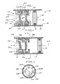
- FIG 3 which is a cross sectional view through the valve arrangement of Figure 2 taken on the line 3 - 3, illustrates the guide structure 28 end - on.
- the guide structure includes four vanes 30A, 30B, 30C and 30D respectively circumferentially displaced at 90° relatively to one another.
- Each vane extends radially inwardly by a maximum distance 32.
- each vane has a stepped configuration with a smaller step extending radially inwardly by a distance 34.
- First and second valve members 36 and 38 respectively are positioned inside the guide structures 26 and 28 respectively.
- Each valve member is made from a suitable material, for example polyurethane or glass-filled nylon, and is in the nature of a round disc with a diameter 40 ( Figure 3 ) which is slightly less than the spacing between those portions of the vanes which project inwardly by the radial distance 34.
- the guide structures thus form cages which allow for movement of the respective valve members in an axial direction through the volume 20. Nonetheless, as is evident from Figure 2 , the guide structures are such that the valve members can tilt to a limited extent and are not necessarily always at a right angle to a longitudinal axis 44 which extends through the volume 20 and the bore 18.
- An arrow 46 in Figure 1 indicates the direction of fluid flow into the volume 20. Assume that the piston 14 is moving to the right in the direction of an arrow 48. A particle 50 is shown suspended in the fluid entering a mouth 52 to the volume. As the piston moves to the right, fluid pressure inside the volume between the piston and the second valve member 38 is reduced and the valve member is displaced to the right. A similar situation pertains in respect of the first valve member 36. Fluid therefore flows through the mouth 52 and around each valve member 36 and 38 as is indicated by means of arrow lines 60.
- FIG. 2 illustrates a situation which the invention is intended to address.
- the piston 14 reaches the end of its stroke and starts moving in the reverse direction along the bore 18.
- the pressure on the right hand side of each valve member tends to increase and the valve members, which are free to move inside their respective guide structures, are displaced to the left.
- the particle 50 is shown trapped between opposing surfaces of the valve seat 22 and the valve member 36 and therefore prevents the valve member from engaging with a sealing action with the seat 22.
- the valve member 38 however is in sealing engagement with its seat 24.
- the trapped particle may allow a degree of fluid backflow to take place in the reverse direction (opposing the arrow 46) via the non-seated valve member 36.
- pressure in the chamber to the right of the valve member 38 increases and fluid can be expelled from the chamber via a suitable port or duct, not shown.
- valve members 36 and 38 The likelihood that particles dispersed in the fluid will simultaneously prevent the valve members 36 and 38 from engaging in a sealing manner with their respective seats is remote.
- a further factor to be borne in mind is that it is possible to increase the number of valve members and seats from 2 to 3 or even more if required.
- the size of the particle 50 which can enter the volume 20 is restricted by using an appropriate strainer or filter. In this way it is ensured that a particle which does enter the volume is small enough to follow the path 60.
- the particle should have a maximum cross sectional dimension which is less than the distance marked 64 in Figure 1 i.e. the spacing between the limiting portion of the guide structure and the opposing surface of the valve seat, and which is also less than the distance marked 66 in Figure 3 which is the separation in a radial sense between a peripheral edge of the valve member and an opposing inner surface of the body 12.
- FIG 4 illustrates a valve assembly 70 which includes a first valve arrangement 10A and a second valve arrangement 10B with each valve arrangement being of the kind shown in Figures 1 to 3 , a body 12A, and a piston 14A which has an active portion moving inside an annular space 72.
- Fluid which is to be pumped is drawn from a fluid source 74 and is passed through a filter 76 in accordance with the guidelines which have been referred to. Fluid can enter a mouth 52A to a volume 20A occupied by the first valve arrangement 10A.
- the second valve arrangement is positioned inside a second volume 20B.
- a chamber 78 is defined between the two valve arrangements.
- the pressure in the volume 78 is reduced and the valve members 36A and 38A are opened (disengaged from their seats). Fluid 74 then flows through the filter 76 and into the volume 78 to make up the fluid which is pumped by the piston from the annular space 72.
- valve arrangements are shown in a common housing. This is not necessarily the case for the valve arrangements could be in separate housings which are connected in any appropriate way to a common chamber.
- the invention makes it possible to dispense a fluid in a precise manner. This is particularly beneficial in the mixing of a passive gel with an activator to produce a gel-type explosive.
Landscapes
- Engineering & Computer Science (AREA)
- General Engineering & Computer Science (AREA)
- Mechanical Engineering (AREA)
- Check Valves (AREA)
- Multiple-Way Valves (AREA)
- Details Of Reciprocating Pumps (AREA)
Priority Applications (1)
| Application Number | Priority Date | Filing Date | Title |
|---|---|---|---|
| PL07866150T PL2084440T3 (pl) | 2006-11-21 | 2007-11-20 | Jednokierunkowy układ zaworowy |
Applications Claiming Priority (2)
| Application Number | Priority Date | Filing Date | Title |
|---|---|---|---|
| ZA200609691 | 2006-11-21 | ||
| PCT/ZA2007/000076 WO2008064375A1 (en) | 2006-11-21 | 2007-11-20 | Check valve arrangement |
Publications (2)
| Publication Number | Publication Date |
|---|---|
| EP2084440A1 EP2084440A1 (en) | 2009-08-05 |
| EP2084440B1 true EP2084440B1 (en) | 2012-01-11 |
Family
ID=39273551
Family Applications (1)
| Application Number | Title | Priority Date | Filing Date |
|---|---|---|---|
| EP07866150A Not-in-force EP2084440B1 (en) | 2006-11-21 | 2007-11-20 | Check valve arrangement |
Country Status (14)
| Country | Link |
|---|---|
| EP (1) | EP2084440B1 (pl) |
| AP (1) | AP2543A (pl) |
| AR (1) | AR063859A1 (pl) |
| AT (1) | ATE541153T1 (pl) |
| BR (1) | BRPI0718968A2 (pl) |
| CL (1) | CL2007003335A1 (pl) |
| DK (1) | DK2084440T3 (pl) |
| EG (1) | EG25878A (pl) |
| MX (1) | MX2009005110A (pl) |
| PE (1) | PE20081209A1 (pl) |
| PL (1) | PL2084440T3 (pl) |
| PT (1) | PT2084440E (pl) |
| WO (1) | WO2008064375A1 (pl) |
| ZA (1) | ZA200902838B (pl) |
Family Cites Families (4)
| Publication number | Priority date | Publication date | Assignee | Title |
|---|---|---|---|---|
| GB814287A (en) | 1955-07-04 | 1959-06-03 | Herbert Ruediger Gerdts | Improvements in or relating to non-return valves |
| DE3426670A1 (de) * | 1984-07-19 | 1986-01-30 | Heilmeier & Weinlein Fabrik für Oel-Hydraulik GmbH & Co KG, 8000 München | Plaettchen-rueckschlag-ventil |
| DE20013763U1 (de) * | 2000-08-10 | 2001-02-15 | Brako Vertriebs-Gesellschaft mbH, 46483 Wesel | Ventileinrichtung für eine Pumpe, insbesondere Handkolbenpumpe |
| US7128088B2 (en) * | 2004-10-07 | 2006-10-31 | Danfoss Flomatic Corporation | Backflow preventer |
-
2007
- 2007-11-19 AR ARP070105134A patent/AR063859A1/es active IP Right Grant
- 2007-11-20 AP AP2009004844A patent/AP2543A/xx active
- 2007-11-20 WO PCT/ZA2007/000076 patent/WO2008064375A1/en not_active Ceased
- 2007-11-20 EP EP07866150A patent/EP2084440B1/en not_active Not-in-force
- 2007-11-20 AT AT07866150T patent/ATE541153T1/de active
- 2007-11-20 DK DK07866150.1T patent/DK2084440T3/da active
- 2007-11-20 PE PE2007001617A patent/PE20081209A1/es not_active Application Discontinuation
- 2007-11-20 PL PL07866150T patent/PL2084440T3/pl unknown
- 2007-11-20 BR BRPI0718968A patent/BRPI0718968A2/pt not_active Application Discontinuation
- 2007-11-20 MX MX2009005110A patent/MX2009005110A/es active IP Right Grant
- 2007-11-20 PT PT07866150T patent/PT2084440E/pt unknown
- 2007-11-21 CL CL200703335A patent/CL2007003335A1/es unknown
-
2009
- 2009-04-23 ZA ZA200902838A patent/ZA200902838B/xx unknown
- 2009-04-27 EG EG2009040583A patent/EG25878A/xx active
Also Published As
| Publication number | Publication date |
|---|---|
| EG25878A (en) | 2012-09-23 |
| EP2084440A1 (en) | 2009-08-05 |
| AP2009004844A0 (en) | 2009-04-30 |
| AR063859A1 (es) | 2009-02-25 |
| AP2543A (en) | 2012-12-20 |
| PL2084440T3 (pl) | 2012-07-31 |
| ATE541153T1 (de) | 2012-01-15 |
| MX2009005110A (es) | 2009-09-23 |
| WO2008064375A1 (en) | 2008-05-29 |
| PT2084440E (pt) | 2012-03-23 |
| ZA200902838B (en) | 2010-03-31 |
| DK2084440T3 (da) | 2012-03-12 |
| PE20081209A1 (es) | 2008-09-04 |
| BRPI0718968A2 (pt) | 2018-10-30 |
| CL2007003335A1 (es) | 2008-06-06 |
Similar Documents
| Publication | Publication Date | Title |
|---|---|---|
| US7364412B2 (en) | System, method, and apparatus for valve stop assembly in a reciprocating pump | |
| CN104812997B (zh) | 凸轮轴调节装置和用于凸轮轴调节装置的中央阀 | |
| US10550950B2 (en) | Check valve with nylon cage insert | |
| CN106795751A (zh) | 带有润滑系统的旋转式等压压力交换器系统 | |
| EP1232351B1 (en) | Unitized spherical profile check valve with replaceable sealing element | |
| US9739275B2 (en) | Self-cleaning disc valve for piston pump | |
| CN102686883A (zh) | 用于车辆液压制动系统的活塞泵 | |
| US20160319812A1 (en) | Pneumatic timing valve | |
| EP3907396A1 (en) | Fuel filter assembly | |
| CN102652224A (zh) | 高性能电子稳定控制泵组件 | |
| KR20080041696A (ko) | 압력 릴리프 밸브 | |
| US20190301454A1 (en) | Rotary piston pump having a sealing chamber seal | |
| US12128337B2 (en) | Fuel filter assembly | |
| EP2084440B1 (en) | Check valve arrangement | |
| CN100485191C (zh) | 具有改善的压力形成动力性的活塞泵 | |
| CN103282654B (zh) | 具有节流部的泵 | |
| EP1510694A1 (en) | Pump valve assembly | |
| EP3376030B1 (en) | Fluid pump with rotating pumping element wear reduction | |
| DE112011104568B4 (de) | Kompressor mit einem Regelventil einer Öffnung in einer Ansaugpassage | |
| US8360746B2 (en) | Inverted pressure regulating valve for an engine oil pump | |
| EP0393800A2 (en) | Valve device | |
| CN111442009B (zh) | 一种单向阀组件及液压马达 | |
| US20180223817A1 (en) | Reciprocating Pump Having a Combination Check Valve and Relief Valve | |
| CN108692070B (zh) | 压缩机 | |
| US20240418282A1 (en) | Valve with replaceable hard inserts |
Legal Events
| Date | Code | Title | Description |
|---|---|---|---|
| PUAI | Public reference made under article 153(3) epc to a published international application that has entered the european phase |
Free format text: ORIGINAL CODE: 0009012 |
|
| 17P | Request for examination filed |
Effective date: 20090615 |
|
| AK | Designated contracting states |
Kind code of ref document: A1 Designated state(s): AT BE BG CH CY CZ DE DK EE ES FI FR GB GR HU IE IS IT LI LT LU LV MC MT NL PL PT RO SE SI SK TR |
|
| DAX | Request for extension of the european patent (deleted) | ||
| 17Q | First examination report despatched |
Effective date: 20100401 |
|
| RAP1 | Party data changed (applicant data changed or rights of an application transferred) |
Owner name: AEL MINING SERVICES LIMITED |
|
| GRAP | Despatch of communication of intention to grant a patent |
Free format text: ORIGINAL CODE: EPIDOSNIGR1 |
|
| GRAS | Grant fee paid |
Free format text: ORIGINAL CODE: EPIDOSNIGR3 |
|
| GRAA | (expected) grant |
Free format text: ORIGINAL CODE: 0009210 |
|
| AK | Designated contracting states |
Kind code of ref document: B1 Designated state(s): AT BE BG CH CY CZ DE DK EE ES FI FR GB GR HU IE IS IT LI LT LU LV MC MT NL PL PT RO SE SI SK TR |
|
| REG | Reference to a national code |
Ref country code: GB Ref legal event code: FG4D |
|
| REG | Reference to a national code |
Ref country code: CH Ref legal event code: EP |
|
| REG | Reference to a national code |
Ref country code: AT Ref legal event code: REF Ref document number: 541153 Country of ref document: AT Kind code of ref document: T Effective date: 20120115 |
|
| REG | Reference to a national code |
Ref country code: IE Ref legal event code: FG4D |
|
| RIN2 | Information on inventor provided after grant (corrected) |
Inventor name: BUEHRMANN, RUDOLPH Inventor name: BUEHRMANN, RUDOLPH TEODOR Inventor name: NIEMANN, FRANK |
|
| REG | Reference to a national code |
Ref country code: DK Ref legal event code: T3 |
|
| REG | Reference to a national code |
Ref country code: DE Ref legal event code: R096 Ref document number: 602007020077 Country of ref document: DE Effective date: 20120315 |
|
| REG | Reference to a national code |
Ref country code: PT Ref legal event code: SC4A Free format text: AVAILABILITY OF NATIONAL TRANSLATION Effective date: 20120313 |
|
| REG | Reference to a national code |
Ref country code: SE Ref legal event code: TRGR |
|
| REG | Reference to a national code |
Ref country code: NL Ref legal event code: VDEP Effective date: 20120111 |
|
| PG25 | Lapsed in a contracting state [announced via postgrant information from national office to epo] |
Ref country code: SI Free format text: LAPSE BECAUSE OF FAILURE TO SUBMIT A TRANSLATION OF THE DESCRIPTION OR TO PAY THE FEE WITHIN THE PRESCRIBED TIME-LIMIT Effective date: 20120111 |
|
| REG | Reference to a national code |
Ref country code: GR Ref legal event code: EP Ref document number: 20120400766 Country of ref document: GR Effective date: 20120518 |
|
| LTIE | Lt: invalidation of european patent or patent extension |
Effective date: 20120111 |
|
| PG25 | Lapsed in a contracting state [announced via postgrant information from national office to epo] |
Ref country code: BE Free format text: LAPSE BECAUSE OF FAILURE TO SUBMIT A TRANSLATION OF THE DESCRIPTION OR TO PAY THE FEE WITHIN THE PRESCRIBED TIME-LIMIT Effective date: 20120111 Ref country code: NL Free format text: LAPSE BECAUSE OF FAILURE TO SUBMIT A TRANSLATION OF THE DESCRIPTION OR TO PAY THE FEE WITHIN THE PRESCRIBED TIME-LIMIT Effective date: 20120111 Ref country code: LT Free format text: LAPSE BECAUSE OF FAILURE TO SUBMIT A TRANSLATION OF THE DESCRIPTION OR TO PAY THE FEE WITHIN THE PRESCRIBED TIME-LIMIT Effective date: 20120111 Ref country code: IS Free format text: LAPSE BECAUSE OF FAILURE TO SUBMIT A TRANSLATION OF THE DESCRIPTION OR TO PAY THE FEE WITHIN THE PRESCRIBED TIME-LIMIT Effective date: 20120511 Ref country code: BG Free format text: LAPSE BECAUSE OF FAILURE TO SUBMIT A TRANSLATION OF THE DESCRIPTION OR TO PAY THE FEE WITHIN THE PRESCRIBED TIME-LIMIT Effective date: 20120411 |
|
| REG | Reference to a national code |
Ref country code: PL Ref legal event code: T3 |
|
| PG25 | Lapsed in a contracting state [announced via postgrant information from national office to epo] |
Ref country code: LV Free format text: LAPSE BECAUSE OF FAILURE TO SUBMIT A TRANSLATION OF THE DESCRIPTION OR TO PAY THE FEE WITHIN THE PRESCRIBED TIME-LIMIT Effective date: 20120111 |
|
| REG | Reference to a national code |
Ref country code: AT Ref legal event code: MK05 Ref document number: 541153 Country of ref document: AT Kind code of ref document: T Effective date: 20120111 |
|
| PG25 | Lapsed in a contracting state [announced via postgrant information from national office to epo] |
Ref country code: CY Free format text: LAPSE BECAUSE OF FAILURE TO SUBMIT A TRANSLATION OF THE DESCRIPTION OR TO PAY THE FEE WITHIN THE PRESCRIBED TIME-LIMIT Effective date: 20120111 |
|
| PG25 | Lapsed in a contracting state [announced via postgrant information from national office to epo] |
Ref country code: RO Free format text: LAPSE BECAUSE OF FAILURE TO SUBMIT A TRANSLATION OF THE DESCRIPTION OR TO PAY THE FEE WITHIN THE PRESCRIBED TIME-LIMIT Effective date: 20120111 Ref country code: EE Free format text: LAPSE BECAUSE OF FAILURE TO SUBMIT A TRANSLATION OF THE DESCRIPTION OR TO PAY THE FEE WITHIN THE PRESCRIBED TIME-LIMIT Effective date: 20120111 |
|
| PLBE | No opposition filed within time limit |
Free format text: ORIGINAL CODE: 0009261 |
|
| STAA | Information on the status of an ep patent application or granted ep patent |
Free format text: STATUS: NO OPPOSITION FILED WITHIN TIME LIMIT |
|
| PG25 | Lapsed in a contracting state [announced via postgrant information from national office to epo] |
Ref country code: IT Free format text: LAPSE BECAUSE OF FAILURE TO SUBMIT A TRANSLATION OF THE DESCRIPTION OR TO PAY THE FEE WITHIN THE PRESCRIBED TIME-LIMIT Effective date: 20120111 Ref country code: SK Free format text: LAPSE BECAUSE OF FAILURE TO SUBMIT A TRANSLATION OF THE DESCRIPTION OR TO PAY THE FEE WITHIN THE PRESCRIBED TIME-LIMIT Effective date: 20120111 |
|
| 26N | No opposition filed |
Effective date: 20121012 |
|
| PG25 | Lapsed in a contracting state [announced via postgrant information from national office to epo] |
Ref country code: AT Free format text: LAPSE BECAUSE OF FAILURE TO SUBMIT A TRANSLATION OF THE DESCRIPTION OR TO PAY THE FEE WITHIN THE PRESCRIBED TIME-LIMIT Effective date: 20120111 |
|
| REG | Reference to a national code |
Ref country code: DE Ref legal event code: R097 Ref document number: 602007020077 Country of ref document: DE Effective date: 20121012 |
|
| PG25 | Lapsed in a contracting state [announced via postgrant information from national office to epo] |
Ref country code: ES Free format text: LAPSE BECAUSE OF FAILURE TO SUBMIT A TRANSLATION OF THE DESCRIPTION OR TO PAY THE FEE WITHIN THE PRESCRIBED TIME-LIMIT Effective date: 20120422 |
|
| REG | Reference to a national code |
Ref country code: CH Ref legal event code: PL |
|
| PG25 | Lapsed in a contracting state [announced via postgrant information from national office to epo] |
Ref country code: LI Free format text: LAPSE BECAUSE OF NON-PAYMENT OF DUE FEES Effective date: 20121130 Ref country code: CH Free format text: LAPSE BECAUSE OF NON-PAYMENT OF DUE FEES Effective date: 20121130 |
|
| PG25 | Lapsed in a contracting state [announced via postgrant information from national office to epo] |
Ref country code: MT Free format text: LAPSE BECAUSE OF FAILURE TO SUBMIT A TRANSLATION OF THE DESCRIPTION OR TO PAY THE FEE WITHIN THE PRESCRIBED TIME-LIMIT Effective date: 20120111 |
|
| PG25 | Lapsed in a contracting state [announced via postgrant information from national office to epo] |
Ref country code: MC Free format text: LAPSE BECAUSE OF NON-PAYMENT OF DUE FEES Effective date: 20121130 |
|
| PG25 | Lapsed in a contracting state [announced via postgrant information from national office to epo] |
Ref country code: LU Free format text: LAPSE BECAUSE OF NON-PAYMENT OF DUE FEES Effective date: 20121120 |
|
| PG25 | Lapsed in a contracting state [announced via postgrant information from national office to epo] |
Ref country code: HU Free format text: LAPSE BECAUSE OF FAILURE TO SUBMIT A TRANSLATION OF THE DESCRIPTION OR TO PAY THE FEE WITHIN THE PRESCRIBED TIME-LIMIT Effective date: 20071120 |
|
| PGFP | Annual fee paid to national office [announced via postgrant information from national office to epo] |
Ref country code: DK Payment date: 20141114 Year of fee payment: 8 |
|
| PGFP | Annual fee paid to national office [announced via postgrant information from national office to epo] |
Ref country code: FI Payment date: 20141117 Year of fee payment: 8 Ref country code: GB Payment date: 20141031 Year of fee payment: 8 Ref country code: SE Payment date: 20141124 Year of fee payment: 8 Ref country code: TR Payment date: 20141110 Year of fee payment: 8 Ref country code: GR Payment date: 20141030 Year of fee payment: 8 Ref country code: CZ Payment date: 20141104 Year of fee payment: 8 Ref country code: IE Payment date: 20141029 Year of fee payment: 8 |
|
| PGFP | Annual fee paid to national office [announced via postgrant information from national office to epo] |
Ref country code: PT Payment date: 20141029 Year of fee payment: 8 Ref country code: FR Payment date: 20141127 Year of fee payment: 8 Ref country code: PL Payment date: 20141105 Year of fee payment: 8 |
|
| PGFP | Annual fee paid to national office [announced via postgrant information from national office to epo] |
Ref country code: DE Payment date: 20150129 Year of fee payment: 8 |
|
| REG | Reference to a national code |
Ref country code: PT Ref legal event code: MM4A Free format text: LAPSE DUE TO NON-PAYMENT OF FEES Effective date: 20160520 |
|
| REG | Reference to a national code |
Ref country code: DE Ref legal event code: R119 Ref document number: 602007020077 Country of ref document: DE |
|
| REG | Reference to a national code |
Ref country code: DK Ref legal event code: EBP Effective date: 20151130 |
|
| GBPC | Gb: european patent ceased through non-payment of renewal fee |
Effective date: 20151120 |
|
| PG25 | Lapsed in a contracting state [announced via postgrant information from national office to epo] |
Ref country code: GR Free format text: LAPSE BECAUSE OF NON-PAYMENT OF DUE FEES Effective date: 20160602 Ref country code: CZ Free format text: LAPSE BECAUSE OF NON-PAYMENT OF DUE FEES Effective date: 20151120 |
|
| REG | Reference to a national code |
Ref country code: IE Ref legal event code: MM4A |
|
| REG | Reference to a national code |
Ref country code: FR Ref legal event code: ST Effective date: 20160729 |
|
| PG25 | Lapsed in a contracting state [announced via postgrant information from national office to epo] |
Ref country code: PT Free format text: LAPSE BECAUSE OF NON-PAYMENT OF DUE FEES Effective date: 20160520 Ref country code: SE Free format text: LAPSE BECAUSE OF NON-PAYMENT OF DUE FEES Effective date: 20151121 |
|
| REG | Reference to a national code |
Ref country code: GR Ref legal event code: ML Ref document number: 20120400766 Country of ref document: GR Effective date: 20160602 |
|
| PG25 | Lapsed in a contracting state [announced via postgrant information from national office to epo] |
Ref country code: IE Free format text: LAPSE BECAUSE OF NON-PAYMENT OF DUE FEES Effective date: 20151120 Ref country code: DE Free format text: LAPSE BECAUSE OF NON-PAYMENT OF DUE FEES Effective date: 20160601 Ref country code: DK Free format text: LAPSE BECAUSE OF NON-PAYMENT OF DUE FEES Effective date: 20151130 Ref country code: GB Free format text: LAPSE BECAUSE OF NON-PAYMENT OF DUE FEES Effective date: 20151120 |
|
| PG25 | Lapsed in a contracting state [announced via postgrant information from national office to epo] |
Ref country code: FR Free format text: LAPSE BECAUSE OF NON-PAYMENT OF DUE FEES Effective date: 20151130 |
|
| PG25 | Lapsed in a contracting state [announced via postgrant information from national office to epo] |
Ref country code: PL Free format text: LAPSE BECAUSE OF NON-PAYMENT OF DUE FEES Effective date: 20151120 |
|
| PG25 | Lapsed in a contracting state [announced via postgrant information from national office to epo] |
Ref country code: FI Free format text: LAPSE BECAUSE OF NON-PAYMENT OF DUE FEES Effective date: 20151120 |
|
| PG25 | Lapsed in a contracting state [announced via postgrant information from national office to epo] |
Ref country code: TR Free format text: LAPSE BECAUSE OF NON-PAYMENT OF DUE FEES Effective date: 20151120 |