EP2082954A1 - Engine with single cylinder or juxtaposed multiple cylinders and saddle ride-type vehicle with the same - Google Patents
Engine with single cylinder or juxtaposed multiple cylinders and saddle ride-type vehicle with the same Download PDFInfo
- Publication number
- EP2082954A1 EP2082954A1 EP07831935A EP07831935A EP2082954A1 EP 2082954 A1 EP2082954 A1 EP 2082954A1 EP 07831935 A EP07831935 A EP 07831935A EP 07831935 A EP07831935 A EP 07831935A EP 2082954 A1 EP2082954 A1 EP 2082954A1
- Authority
- EP
- European Patent Office
- Prior art keywords
- cylinder
- crankshaft
- engine
- axis
- frame
- Prior art date
- Legal status (The legal status is an assumption and is not a legal conclusion. Google has not performed a legal analysis and makes no representation as to the accuracy of the status listed.)
- Granted
Links
Images







Classifications
-
- F—MECHANICAL ENGINEERING; LIGHTING; HEATING; WEAPONS; BLASTING
- F02—COMBUSTION ENGINES; HOT-GAS OR COMBUSTION-PRODUCT ENGINE PLANTS
- F02B—INTERNAL-COMBUSTION PISTON ENGINES; COMBUSTION ENGINES IN GENERAL
- F02B61/00—Adaptations of engines for driving vehicles or for driving propellers; Combinations of engines with gearing
- F02B61/02—Adaptations of engines for driving vehicles or for driving propellers; Combinations of engines with gearing for driving cycles
-
- B—PERFORMING OPERATIONS; TRANSPORTING
- B62—LAND VEHICLES FOR TRAVELLING OTHERWISE THAN ON RAILS
- B62K—CYCLES; CYCLE FRAMES; CYCLE STEERING DEVICES; RIDER-OPERATED TERMINAL CONTROLS SPECIALLY ADAPTED FOR CYCLES; CYCLE AXLE SUSPENSIONS; CYCLE SIDECARS, FORECARS, OR THE LIKE
- B62K11/00—Motorcycles, engine-assisted cycles or motor scooters with one or two wheels
- B62K11/02—Frames
- B62K11/04—Frames characterised by the engine being between front and rear wheels
-
- B—PERFORMING OPERATIONS; TRANSPORTING
- B62—LAND VEHICLES FOR TRAVELLING OTHERWISE THAN ON RAILS
- B62K—CYCLES; CYCLE FRAMES; CYCLE STEERING DEVICES; RIDER-OPERATED TERMINAL CONTROLS SPECIALLY ADAPTED FOR CYCLES; CYCLE AXLE SUSPENSIONS; CYCLE SIDECARS, FORECARS, OR THE LIKE
- B62K19/00—Cycle frames
- B62K19/18—Joints between frame members
- B62K19/28—Means for strengthening joints
-
- B—PERFORMING OPERATIONS; TRANSPORTING
- B62—LAND VEHICLES FOR TRAVELLING OTHERWISE THAN ON RAILS
- B62K—CYCLES; CYCLE FRAMES; CYCLE STEERING DEVICES; RIDER-OPERATED TERMINAL CONTROLS SPECIALLY ADAPTED FOR CYCLES; CYCLE AXLE SUSPENSIONS; CYCLE SIDECARS, FORECARS, OR THE LIKE
- B62K19/00—Cycle frames
- B62K19/30—Frame parts shaped to receive other cycle parts or accessories
- B62K19/32—Steering heads
-
- F—MECHANICAL ENGINEERING; LIGHTING; HEATING; WEAPONS; BLASTING
- F02—COMBUSTION ENGINES; HOT-GAS OR COMBUSTION-PRODUCT ENGINE PLANTS
- F02F—CYLINDERS, PISTONS OR CASINGS, FOR COMBUSTION ENGINES; ARRANGEMENTS OF SEALINGS IN COMBUSTION ENGINES
- F02F7/00—Casings, e.g. crankcases
- F02F7/0002—Cylinder arrangements
- F02F7/0019—Cylinders and crankshaft not in one plane (deaxation)
-
- Y—GENERAL TAGGING OF NEW TECHNOLOGICAL DEVELOPMENTS; GENERAL TAGGING OF CROSS-SECTIONAL TECHNOLOGIES SPANNING OVER SEVERAL SECTIONS OF THE IPC; TECHNICAL SUBJECTS COVERED BY FORMER USPC CROSS-REFERENCE ART COLLECTIONS [XRACs] AND DIGESTS
- Y10—TECHNICAL SUBJECTS COVERED BY FORMER USPC
- Y10T—TECHNICAL SUBJECTS COVERED BY FORMER US CLASSIFICATION
- Y10T74/00—Machine element or mechanism
- Y10T74/13—Machine starters
Definitions
- the present invention relates to a single-cylinder or in-line multi-cylinder engine and a straddle-type vehicle provided with the same.
- Patent Document 1 discloses a motorcycle in which an engine is mounted in a manner that a cylinder thereof is inclined rearward.
- Patent Document 1 discloses that three merits can be obtained by rearward inclination of the cylinder. The first merit is that load distribution on a front wheel can be increased. The second merit is that the body weight can be reduced. The third merit is that traction can be improved with extension of a rear swing arm.
- mass concentration in the engine can be raised, for example. More specifically, there are at least three heavyweight objects in the engine, which are a cylinder head, a crankshaft, and a gear change mechanism. A method of disposing these three heavyweight objects as close as possible can be raised. The application of the method allows the cylinder head as the heavyweight obj ect to be located between the crankshaft and the gear change mechanism. Then, distances between the center of gravity of the vehicle and the centers of gravity of the cylinder head, the crankshaft, and the gear change mechanism become shorter. Therefore, the mass can be concentrated. As a result, the motion performance can be further improved.
- the present invention has been made in view of a foregoing problem, and thus an object thereof is to concentrate the mass in an engine equipped with a crankshaft, a cylinder head, and a gear change mechanism.
- the invention provides a single-cylinder or in-line multi-cylinder engine.
- the engine according to the invention includes a crankshaft, a piston, a cylinder body, a cylinder head, and a gear change mechanism.
- the piston is connected to the crankshaft.
- a cylinder is formed in the cylinder body.
- the piston is housed in the cylinder.
- the cylinder head is mounted on an end of the cylinder body.
- the gear change mechanism is disposed behind the crankshaft.
- An axis of the cylinder extends upward obliquely to the rear from the crankshaft side. The axis of the cylinder passes through in front of an axis of the crankshaft when viewed from a direction that the crankshaft extends.
- the invention also provides a straddle-type vehicle including the engine according to the invention.
- mass concentration is made possible in an engine equipped with a crankshaft, a cylinder head, and a gear change mechanism.
- a straddle-type vehicle according to the invention is not limited to the so-called off-road type motorcycle 1 shown in FIG. 1 .
- the "straddle-type vehicle" in the invention means a vehicle on which a rider straddles a seat. Therefore, the straddle-type vehicle according to the invention may be an All Terrain Vehicle (ATV) or the like.
- the straddle-type vehicle according to the invention may also be a motorcycle other than an off-road vehicle. More specifically, the straddle-type vehicle according to the invention may be a motorcycle in a narrow sense, a moped, a scooter, or the like.
- the "motorcycle” in the invention includes a motorcycle in a narrow sense, a moped, a scooter, an off-road vehicle, and the like.
- the "motorcycle” in the invention includes a vehicle that has a plurality of wheels at least either in the front or in the rear thereof and that changes a traveling direction by tilting a vehicle body.
- the motorcycle 1 has a body frame 9.
- the body frame 9 includes a head pipe 2, a main frame 3, a tank rail 4, a seat rail 5, a backstay 6, a down frame 7, and a lower frame 8.
- the head pipe 2 is disposed at the front end of the body frame 9.
- the main frame 3 is connected to the head pipe 2.
- the main frame 3 extends slightly downward to the rear from the head pipe 2.
- the main frame 3 is bent in the middle and extends approximately downward therefrom.
- the tank rail 4 is disposed between the head pipe 2 and the main frame 3. A front end of the tank rail 4 is connected to the head pipe 2. Meanwhile, a rear end of the tank rail 4 is connected to the main frame 3. A resinous fuel tank 25 is disposed above the tank rail 4. The fuel tank 25 is disposed such that it is held between a left tank rail 4a and a right tank rail 4b, both of which constitute the tank rail 4. The seat 26 is disposed behind the fuel tank 25.
- the seat rail 5 is connected to the middle of the main frame 3.
- the seat rail 5 extends slightly upward to the rear from the main frame 3.
- a rear end of the seat rail 5 is connected to a rear end of the main frame 3 through the backstay 6.
- the down frame 7 is connected to the head pipe 2.
- the down frame 7 extends downward to the rear from the head pipe 2 in a position below the main frame 3.
- a rear end of the down frame 7 and the rear end of the main frame 3 are connected through the lower frame 8.
- a steering shaft which is not shown, is rotatably inserted in the head pipe 2.
- Handlebars 10 are mounted on top of the steering shaft.
- a pair of front forks 12 extending obliquely downward to the front is attached to the steering shaft.
- a front wheel 13 is rotatably attached to lower ends of the paired front forks 12.
- a front fender 14 is disposed above the front wheel 13. The front wheel 13 is covered by this front fender 14 from above.
- a pivot shaft 19 is attached to the rear end of the main frame 3.
- a rear arm 20 is swingably attached to the pivot shaft 19.
- a rear wheel 21 is rotatably attached to a rear end of the rear arm 20.
- the rear arm 20 is connected to an end of a rear suspension 23 via a coupling member 24.
- the other end of the rear suspension 23 is connected to the main frame 3. Shocks from the vertical swings of the rear arm 20 are absorbed by this rear suspension 23.
- a rear fender 22 is disposed above the rear wheel 21.
- the rear wheel 21 is covered by this rear fender 22 from above.
- an engine 15 is mounted in an area surrounded by the main frame 3, the down frame 7, and the lower frame 8 in a side view.
- a radiator 16 is disposed in front of and above the engine 15.
- the radiator 16 is arranged to extend downward slightly to the rear.
- the engine 15 is cooled down by a function of the radiator 16.
- An exhaust pipe 17 is connected to a rear portion of the engine 15.
- the exhaust pipe 17 extends rearward from the engine 15.
- the exhaust pipe 17 is connected to a muffler 18.
- the head pipe 2 is made of aluminum.
- the head pipe 2 is formed by semi-solid die casting.
- semi-solid die casting is a method of forming a metal member by die casting metal that is a mixture of a liquid and solid phase.
- the utilization of semi-solid die casting can improve the strength of moldings when compared to the utilization of a regular casting method.
- the head pipe 2 includes a cylindrical section 2b and a body section 2c.
- An insertion hole 2a is formed in the cylindrical section 2b.
- the insertion hole 2a extends in a predetermined direction A.
- the body section 2c is located at the rear of the cylindrical section 2b.
- the body section 2c extends in a downward direction.
- a weld reinforcement 2d shown in FIG. 5 and a weld reinforcement 2e shown in FIG. 2 are formed in portions of the body section 2c of the head pipe 2 at the rear of the cylindrical section 2b.
- the weld reinforcement 2d is formed to project from the left side of the head pipe 2 to the rear.
- the weld reinforcement 2e is formed to project from the right side of the head pipe 2 to the rear.
- a weld part 2f shown in FIG. 6 and a weld part 2g shown in FIG. 2 are formed as frame parts in portions of the head pipe 2 below the weld reinforcements 2d, 2e.
- weld reinforcements 2d, 2e, the weld parts 2f, 2g, and the head pipe 2 are integrally formed by semi-solid die casting.
- a recess 2h is formed in a front portion of the body section 2c.
- the recess 2h opens in the direction A that the insertion hole 2a extends. Therefore, as shown in FIG. 7 , the body section 2c is formed to have a U-shaped cross section.
- the main frame 3 is made of aluminum as the head pipe 2 is.
- the main frame 3 is also formed by semi-solid die casting as the head pipe 2 is.
- the main frame 3 includes a left frame 3a located on the left side and a right frame 3b located on the right side.
- the left frame 3a and the right frame 3b of the main frame 3 are arranged to extend rearward and to have predetermined spacing therebetween in a vehicle width direction in a plan view. Front ends of the left frame 3a and the right frame 3b are respectively welded to the weld parts 2f, 2g in the body section 2c of the head pipe 2. Therefore, the left frame 3a and the right frame 3b are formed in such a U-shape in cross section that they approach each other toward the body section 2c of the head pipe 2.
- connections 3c, 3d are respectively formed on top of the left frame 3a and the right frame 3b.
- the tank rail 4 is welded to the connections 3c, 3d.
- the connections 3c, 3d shown in FIG. 2 are arranged to be fitted to a connection 4c and a connection 4d of the tank rail 4, respectively.
- the connections 3c, 3d are respectively welded to the connection 4c and the connection 4d.
- the connections 3c, 3d each have a recess 3e on an inner side of a portion thereof that is fitted to the connections 4c, 4d of the tank rail 4.
- portions of the left frame 3a and the right frame 3b near the portions thereof to which the tank rail 4 is welded each have a recess 3f and has a U-shaped cross section.
- a boss 3g is integrally formed on the inside of each recess 3f.
- a support plate 27a and a support plate 27b shown in FIG. 2 for supporting the engine 15 are fixed to the bosses 3g.
- the bosses 3g and the support plate 27a as well as the bosses 3g and the support plate 27b are fixed by screws 50.
- the main frame 3 is formed by semi-solid die casting, it is possible to integrally form the recesses 3e and the bosses 3g with the main frame 3.
- bracket weld parts 3h, 3i are integrally formed in the middle of the left frame 3a and of the right frame 3b in a longitudinal direction, respectively. As shown in FIG. 5 , the bracket weld parts 3h, 3i are formed to extend upward to the inside. Also, as shown in FIGs. 2 and 3 , a rear suspension bracket 28 is welded to the bracket weld parts 3h, 3i. An upper section of the rear suspension 23 shown in FIG. 1 is supported by the rear suspension bracket 28.
- the rear suspension bracket 28 includes a cross pipe 28a and two attachments 28b.
- the cross pipe 28a is formed by extrusion.
- the two attachments 28b are integrally formed with the cross pipe 28a.
- a rear-suspension support hole 28c and a seat-rail support hole 28d are formed in each of the attachments 28b.
- attachments 3j, 3k are respectively formed at a portion of the left frame 3a at the rear of the bracket weld part 3h and at a portion of the right frame 3b at the rear of the bracket weld part 3i.
- the backstay 6 is attached to the attachments 3j, 3k.
- Fixing parts 31, 3m are respectively formed in lower portions of the left frame 3a and the right frame 3b as shown in FIG. 1 .
- the pivot shaft 19 is fixed to the fixing parts 31, 3m.
- Footrest holding plates 29 are respectively fixed to a portion of the left frame 3a, which is lower than the fixing part 31, and to a portion of the right frame 3b, which is lower than the fixing part 3m, with a screw 51.
- a coupling member bracket 30 is welded to the left frame 3a and the right frame 3b at their lower ends.
- the coupling members 24 are attached to the coupling member bracket 30.
- the coupling member bracket 30 includes a cross pipe 30a and two attachments 30b.
- the cross pipe 30a is formed by extrusion.
- the two attachments 30b are integrally formed with the cross pipe 30a.
- a coupling-member support hole 30c is formed in each attachment 30b.
- the left frame 3a and the right frame 3b are formed to extend inward to the front at the front of their lower ends.
- the tank rail 4 is made of aluminum.
- the tank rail 4 is formed by extrusion.
- the tank rail 4 includes the left tank rail 4a located on the left side and the right tank rail 4b located on the right side. As shown in FIG. 10 , the tank rail 4 is made hollow.
- the tank rail 4 includes a wall 4g. An internal space of the tank rail 4 is divided into a hole 4e and a hole 4f by the wall 4g. At least one of the hole 4e and the hole 4f may be communicated with the outside.
- the front end of the left tank rail 4a is welded to the upper left of the body section 2c of the head pipe 2 and the weld reinforcement 2d, which is shown in FIG. 5 .
- the connection 4c at the rear end of the left tank rail 4a is welded to the connection 3c of the left frame 3a.
- the front end of the right tank rail 4b is welded to the upper right of the body section 2c of the head pipe 2 and the weld reinforcement 2e.
- the connection 4d at the rear end of the right tank rail 4b is welded to the connection 3d of the right frame 3b.
- the seat rail 5 includes a left rail 5a located on the left side, a right rail 5b located on the right side, and two reinforcing pipes 5c, 5d.
- the left rail 5a and the right rail 5b are connected by the two reinforcing pipes 5c, 5d.
- front ends of the left rail 5a and the right rail 5b are fixed in the seat-rail support holes 28d in the attachments 28b of the rear suspension bracket 28.
- the backstay 6 includes a left stay 6a located on the left side and a right stay 6b located on the right side. Upper ends of the left stay 6a and the right stay 6b are welded to the left rail 5a and the right rail 5b, respectively. Lower ends of the left stay 6a and the right stay 6b are attached to the attachment 3j on the left frame 3a and the attachment 3k on the right frame 3b, respectively.
- the down frame 7 is made of aluminum.
- the down frame 7 is made by forging.
- a rear surface of the down frame 7 is welded to the head pipe 2.
- a recess 7a is formed in a part of the down frame 7 to which the head pipe 2 is welded.
- the part of the down frame 7 to which the head pipe 2 is welded has a U-shaped cross section.
- a lower part of the down frame 7 is bifurcated into a left frame 7b extending downward to the left and a right frame 7c extending downward to the right.
- Recesses 7d, 7e are respectively formed in the left frame 7b and the right frame 7c.
- support plates 31a, 31b are respectively fixed to the recesses 7d, 7e by screws 52.
- a support bar 32 for supporting the engine 15 is fixed to the support plates 31a, 31b with screws 53.
- the lower frame 8 is made of aluminum.
- the lower frame 8 is formed by extrusion.
- the lower frame 8 includes a left lower frame 8a located on the left side and a right lower frame 8b located on the right side. Front ends of the left lower frame 8a and the right lower frame 8b are welded to lower ends of the left frame 7b and the right frame 7c, respectively.
- support plates 33a, 33b are respectively welded to upper surfaces of the left lower frame 8a and the right lower frame 8b.
- a support bar 34 for supporting the engine 15 is fixed to the support plates 33a, 33b with screws 54.
- Rear ends of the left lower frame 8a and the right lower frame 8b are welded to front portions of lower ends of the left frame 3a and the right frame 3b, respectively.
- the engine 15 is a water-cooled single-cylinder engine.
- the engine 15 may be an in-line multi-cylinder engine.
- the engine 15 may be an air-cooled engine.
- the in-line multi-cylinder engine includes an in-line two cylinder engine.
- the engine 15 includes a crankcase 40, a cylinder body 41, a cylinder head 42, a head cover 43 attached to an end of the cylinder head 42, a gear change mechanism 70, and an oil pump 69.
- crankshaft 44 extending in a vehicle width direction is housed in the crankcase 40.
- a connecting rod 45 is attached to the crankshaft 44.
- a piston 46 is attached to an end of the connecting rod 45.
- a cylinder 41a in a generally cylindrical shape is formed in the cylinder body 41.
- the piston 46 is housed in this cylinder 41a.
- the cylinder body 41 is attached to a front half of the crankcase 40. More specifically, as shown in FIG. 13 , the cylinder body 41 is attached to the crankcase 40 in a manner that a lower portion of the cylinder body 41 is located inside the crankcase 40. Therefore, the cylinder 41a extends into the crankcase 40.
- the cylinder body 41 is attached to the crankcase 40 in a manner that the cylinder 41a inclines rearward to the side of the gear change mechanism 70, which will be described later. More specifically, an axis 41b of the cylinder 41a extends upward obliquely to the rear from the crankshaft 44 side.
- the axis 41b of the cylinder 41a passes through in front of an axis 44a of the crankshaft 44 when viewed from a direction that the crankshaft 44 extends.
- the axis 41b of the cylinder 41a is located in front of a straight line 44b that passes through the axis 44a of the crankshaft 44 and is parallel to the axis 41b.
- a direction in which the crankshaft 44 extends is the same as the vehicle width direction.
- the axis 41b of the cylinder 41a passes through in front of the axis 44a of the crankshaft 44 when viewed from the direction in which the crankshaft 44 extends.
- to dispose a cylinder in such a manner is called to "offset the cylinder".
- the cylinder head 42 is attached to an end of the cylinder body 41.
- a valve mechanism 47 is housed in the cylinder head 42.
- the valve mechanism 47 includes an intake valve 57, an exhaust valve 59, an intake camshaft 48, and an exhaust camshaft 49.
- the intake valve 57 is driven by the intake camshaft 48.
- the intake valve 57 opens and closes an intake port 58.
- the exhaust valve 59 is driven by the exhaust camshaft 49.
- the exhaust valve 59 opens and closes an exhaust port 60.
- a throttle body 61 is attached to the intake port 58. Air and fuel are supplied to a combustion chamber 62 from this throttle body 61 via the intake port 58. Meanwhile, an exhaust pipe 56 is connected to the exhaust port 60. Exhaust gas in the combustion chamber 62 is discharged to the outside through the exhaust port 60 and the exhaust pipe 56.
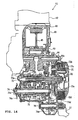
- the gear change mechanism 70 is housed in the crankcase 40. As shown in FIG. 14 , the gear change mechanism 70 includes a transmission 71 and a multi-plate clutch 72.
- the transmission 71 includes a main shaft 73 as an input shaft and a drive shaft 74 as an output shaft.
- the clutch 72 is attached to a right end of the main shaft 73.
- the clutch 72 includes an inner element 72a, an outer element 72b, and a plate group 72c.
- the plate group 72c includes a plurality of clutch plates and a plurality of friction plates. The clutch plates and the friction plates are alternately located. Either the plural clutch plates or the plural friction plates are unable to rotate with respect to the inner element 72a, and the other plates are unable to rotate with respect to the outer element 72b.
- the plate group 72c is located between the inner element 72a and the outer element 72b.
- the plural plates constituting the plate group 72c are brought into contact with each other by pressurizing for rotation transmission between the inner element 72a and the outer element 72b.
- the outer element 72b is rotatable with respect to the main shaft 73.
- a gear 72d is fixed to the outer element 72b.
- the gear 72d meshes with a gear 44c provided on the crankshaft 44. Therefore, the outer element 72b rotates along with the rotation of the crankshaft 44.
- the inner element 72a is attached to the main shaft 73 in a manner that it is unable to rotate with respect to the main shaft 73. Therefore, once the clutch 72 is engaged, the inner element 72a and the main shaft 73 rotate together with the outer element 72b.
- the main shaft 73 includes a main shaft body 73a and a first shift gear group 73b.
- the drive shaft 74 includes a drive shaft body 74a and a second shift gear group 74b.
- the first shift gear group 73b and the second shift gear group 74b mesh with each other.
- a shift gear pair 75 is composed of the first shift gear group 73b and the second shift gear group 74b. The rotation of the main shaft 73 is transmitted to the drive shaft 74 by the shift gear pair 75 in various change gear ratios.
- a sprocket 74c is provided on the left end of the drive shaft 74.
- a drive chain, which is not shown, as a power transmission means to the rear wheel 21 is wound around this sprocket 74c. Accordingly, the rotation of the drive shaft 74 is transmitted to the rear wheel 21.
- a gear 74d is formed at the right end of the drive shaft 74.
- the gear 74d meshes with a one-way gear 76a provided on a kick shaft 76.
- a kick pedal 77 is attached to the kick shaft 76. Therefore, when the kick pedal 77 is operated by the rider, the rotation of the kick shaft 76 is transmitted to the crankshaft 44 via the drive shaft 74, the main shaft 73, and the clutch 72.
- the gear change mechanism 70 is located behind the axis 44a of the crankshaft 44.
- the gear change mechanism 70 is located further behind the lower end of the cylinder body 41.
- the upper end of the main shaft 73 is positioned higher than the axis 44a of the crankshaft 44.
- the upper end of the main shaft 73 is positioned higher than the lower end of the cylinder body 41. In other words, the lower end of the cylinder body 41 is positioned lower than the upper end of the main shaft 73.
- An axis 73c of the main shaft 73 is located generally right behind the axis 44a of the crankshaft 44. Strictly speaking, the axis 73c of the main shaft 73 is located slightly higher than the axis 44a of the crankshaft 44. The axis 73c of the main shaft 73 is located above a straight line L passing through the axis 44a of the crankshaft 44 and an axis 74e of the drive shaft 74.
- the cylinder 41a is inclined rearward, and the cylinder 41a is offset in this embodiment. More specifically, the cylinder 41a is disposed in a manner that the axis 41b of the cylinder 41a extends upward to the rear. At the same time, the cylinder 41a is disposed in a manner that the axis 41b of the cylinder 41a passes through in front of the axis 44a of the crankshaft 44 when viewed from the direction that the crankshaft 44 extends. Therefore, it is possible to concentrate the mass in the engine 15.
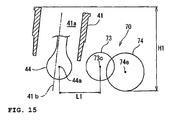
- FIG. 15 is a conceptual view showing positional relationships among the cylinder body 41, the crankshaft 44, and the gear change mechanism 70.
- FIG. 16 is a conceptual view showing positional relationships among a cylinder body 141, a crankshaft 144, and a gear change mechanism 170 when a cylinder 141a is not offset.
- the rearward inclination of the cylinder 141a tends to shorten a distance between the cylinder body 141 and the gear change mechanism 170. This may cause the cylinder body 141 to interfere with the gear change mechanism 170 in location wise. Therefore, it is difficult to sufficiently incline the cylinder 141a rearward. As a result, it is difficult to sufficiently concentrate the mass.
- an axis 173c of a main shaft 173 needs to be located away at the back of an axis 144a of the crankshaft 144.
- the axis 173c of the main shaft 173 needs to be located relatively lower as shown in FIG. 18 .
- a distance L2 between the axis 173c and the axis 144a becomes longer than a distance L1 between the axis 73c and the axis 44a, which is shown in FIG. 15 . Therefore, the crankshaft 144 and the gear change mechanism 170 as heavyweight objects end up being located away from each other. Consequently, the mass tends to be dispersed.
- the cylinder 41a is inclined rearward while the cylinder 41a is offset in this embodiment.
- the first merit is that side thrust and piston slap can be reduced since a motion direction of the piston 46a in an expansion stroke can be set relatively parallel to the connecting rod 45a.
- the second merit is that it is possible to shorten the compression time while extending the expansion time.
- the thirdmerit is that the process volume is increased. Therefore, the offset of the cylinder 41a allows a decrease in a diameter of the cylinder 41a if the engine displacement remains the same. Consequently, reduction in size and weight of the engine 15 is possible.
- the offset amount that is, a distance W between the straight line 44b and the straight line 41b shown in FIG. 13 is not particularly limited; however, it is preferably between 1 and 30 mm. It is more preferably between 5 and 20 mm and is further more preferably between 5 and 15 mm.
- the preferable offset amount from a viewpoint of decreasing the side thrust varies in accordance with speed of the engine 15. More specifically, when the speed of the engine 15 is relatively low such as 6000 rpm or less, it is preferable that the offset amount be large. On the other hand, when the speed of the engine 15 is relatively high, it is preferable that the offset amount be small. Therefore, the invention with which the cylinder 41b is offset is particularly useful for an engine whose performance in a lower speed range is emphasized and for a vehicle provided with the same. From the above viewpoint, it is especially useful for off-road vehicles and ATVs.
- the center of gravity of the motorcycle 1 can be shifted to the rear side with the rearward inclination of the cylinder 41a. Consequently, load distribution on the front wheel 13 decreases. Therefore, the invention is especially useful for a vehicle whose load distribution on the front wheel 13 is preferably decreased. More specifically, it is especially useful for off-road vehicles and the like.
- the lower end of the cylinder body 41 is located lower than the upper end of the gear change mechanism 70. Therefore, it is possible to decrease the distance between the cylinder head 42, which is attached to the upper end of the cylinder body 41, and the gear change mechanism 70 in a vertical direction. Accordingly, further mass concentration can be realized.
- the upper end of the main shaft 73 is located higher than the axis 44a of the crankshaft 44. Therefore, for example, comparing to the case where the axis 44a of the crankshaft 44 is lower than the upper end of the main shaft 73, it is possible to shorten the distance between the cylinder head 42 and the gear change mechanism 70. Consequently, further mass concentration can be realized.
- the axis 73c of the main shaft 73 is located above the straight line L passing through the axis 44a of the crankshaft 44 and the axis 74e of the drive shaft 74. Therefore, for example, comparing to the case where the axis 73c of the main shaft 73 is located on the straight line L, it is possible to shorten the distance between the drive shaft 74 and the crankshaft 44. Accordingly, further mass concentration can be possible, and reduction in size of the engine 15 in a longitudinal direction can also be possible.
- This embodiment describes a case that the axis 73c of the main shaft 73 is located above the straight line L; however, the axis 73c of the main shaft 73 may be located below the straight line L. The above effect can be obtained also in such a case. In other words, it is preferable that the axis 73c of the main shaft 73 be not located on the straight line L.
- the main frame 3 and the tank rail 4 are provided in this embodiment.
- the main frame 3 is directly connected to the head pipe 2.
- the main frame 3 supports the rear arm 20 to which the rear wheel 21 is attached.
- the rear end of the tank rail 4 is connected to the main frame 3. Therefore, it is possible to connect the main frame 3, which supports the rear arm 20 to which the rear wheel 21 is attached, to the head pipe 2.
- the connection between the head pipe 2 and the main frame 3 can be reinforced. Therefore, it is possible to reinforce the connection between the main frame 3 for supporting the rear arm 20 and the head pipe 2 and to suppress an increase in the number of components of the body frame 9.
- the head pipe 2 is formed to extend rearward.
- the head pipe 2 is formed to include the weld parts 2f, 2g to which the main frame 3 is connected. Therefore, it is possible to easily and directly connect the main frame 3 to the weld parts 2f, 2g of the head pipe 2.
- the bosses 3g for supporting the engine 15 are integrally formed with the main frame 3. Therefore, comparing to the case where the bosses 3g for supporting the engine 15 are separately formed from the main frame 3, it is possible to prevent an increase in the number of components for supporting the engine 15.
- the head pipe 2 is provided with the insertion hole 2a in which the steering shaft 11 is inserted and the recess 2h opening in the direction along the direction A in which the insertion hole 2a extends. Therefore, the head pipe 2 having the recess 2h can be easily formed using dies by semi-solid die casting by setting a direction in which the die is pulled out to the direction that the insertion hole 2a extends.
- the left frame 3a and the right frame 3b of the main frame 3 are arranged to extend rearward while making the predetermined spacing therebetween in a vehicle width direction in a plan view.
- the left frame 3a and the right frame 3b are arranged to assume such a U-shape that they approach each other toward the body section 2c of the head pipe 2. Therefore, it is possible to improve rigidity of the body frame 9 in a planar direction.
- the recess 3e is formed in each of the connections 3c, 3d of the main frame 3. More specifically, the recess 3e is formed inside the portion of each of the connections 3c, 3d, which is fitted to the tank rail 4. Therefore, it is possible to reduce the weight of the main frame 3.
- the main frame 3 and the head pipe 2 are formed by semi-solid die casting. Therefore, it is possible to reduce sizes and weights of the main frame 3 and the head pipe 2 in comparison with a case where the main frame 3 and the head pipe 2 are formed by forging or regular die casting.
- parts made by forging are less flexible and less accurate in shape than those made by semi-solid die casting. Therefore, when the main frame 3 and the head pipe 2 are formed by forging, it is difficult to form the main frame 3 and the head pipe 2 in a shape of a recess (U-shape) or in a shape with which predetermined strength can be secured. It is necessary to thicken the main frame 3 and the head pipe 2 if they are made by forging. As a result, the main frame 3 and the head pipe 2 tend to be enlarged, and thus the weights of the main frame 3 and the head pipe 2 tend to increase.
- main frame 3 and the head pipe 2 are formed by common die casting, they become less strong than those formed by semi-solid die casting. Consequently, it is necessary to thicken the main frame 3 and the head pipe 2 in order to secure the predetermined strength thereof. Therefore, there is a tendency that the size of the head pipe 2 as well as the weight thereof increases.
- the engine of the invention may be mounted in a vehicle other than a motorcycle.
- a space for mounting the engine 15 is smaller in a straddle-type vehicle than in a four-wheeled automobile.
- the relatively higher motion performance is requested.
- a space for mounting the engine 15 is especially small. Therefore, the invention with which the mass can be concentrated is useful for straddle-type vehicles, and especially for motorcycles. Since higher motion performance can be realized with the mass concentration, it is especially useful for off-road vehicles and ATVs.
- the above first embodiment describes a case that only the kick pedal 77 shown in FIG. 14 is provided as a starter of the engine 15.
- the invention is not limited to this construction.
- a starter motor 80 may be disposed as a starter either with the kick pedal 77 or without the kick pedal 77.
- FIG. 19 is a schematic conceptual view showing structure of an engine 15a according to the second embodiment.
- FIG. 20 is a schematic side view showing the structure of the engine 15a according to the second embodiment. Descriptions will hereinafter be made of the engine 15a according to the second embodiment with reference to FIGs. 19 and 20 .
- a one-way gear 44d is provided on the left end of the crankshaft 44 in this embodiment.
- This gear 44d meshes with a starter gear 83 through an idle gear 81.
- the starter gear 83 is attached to a rotary shaft 82 of the starter motor 80. Therefore, when the rotary shaft 82 of the starter motor 80 rotates, rotation thereof is transmitted to the crankshaft 44 via the starter gear 83, the idle gear 81, and the one-way gear 44d.
- the starter motor 80 is located above the gear change mechanism 70 and behind the cylinder body 41.
- an axis 82a of the rotary shaft 82 of the starter motor 80 is located above the gear change mechanism 70 and behind the cylinder body 41.
- the starter motor 80 is located above the main shaft 73 in this embodiment.
- the axis 82a is located forward of the rear end of the gear change mechanism 70.
- the axis 82a is located forward of the axis 74e of the drive shaft 74.
- the center of gravity of the engine 15 can be brought closer to the starter motor 80 by disposing the starter motor 80 above the gear change mechanism 70 and behind the cylinder body 41. Therefore, it is possible to further concentrate the mass in the engine 15.
- the axis 82a of the rotary shaft 82 of the starter motor 80 be located within an area surrounded by the straight line L, the straight line 44b, and a tangent L2 to an outline of the drive shaft 74 at the rear end of the drive shaft 74 on the straight line L. Then, it is possible to further concentrate the mass in the engine 15.
- the starter motor 80 is located outside the crankcase 40. In detail, it is located on top of the crankcase 40.
- One end of the rotary shaft 82 of the starter motor 80 is inserted inside the crankcase 40 and is connected with the starter gear 83 located inside the crankcase 40.
- the engine 15 is described by raising a single-cylinder engine as an example.
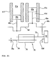
- the engine 15 may be an in-line multi-cylinder engine as shown in FIG. 21 .
- connecting rods 45a, 45b are connected to the crankshaft 44 in FIG. 21 .
- a piston 46a is attached to an end of the connecting rod 45a.
- the piston 46a is housed in a cylinder 41d formed in a cylinder body 41c.
- a piston 46b is attached to an end of the connecting rod 45b.
- the piston 46b is housed in a cylinder 41e formed in a cylinder body 41f.
- the invention is not limited thereto.
- the weld part as a frame fixing part may be separately formed from the head pipe, and the main frame may be connected to the head pipe via the weld part.
- the head pipe and the main frame are formed by semi-solid die casting; however, the invention is not limited to this configuration.
- the head pipe and the main frame may be formed by a method other than semi-solid die casting.
- the head pipe and the main frame may be formed by forging or common die casting.
- the rear suspension bracket is composed of the cross pipe formed by extrusion and the attachments welded to the cross pipe.
- the rear suspension bracket may be formed by semi-solid die casting. This allows simultaneous forming of the cross pipe and the attachments.
- the head pipe and the main frame are formed to have a U-shape in cross section; however, the invention is not limited thereto.
- the head pipe and the main frame may be formed to not have a U-shape in cross section.
- the fuel tank is supported by the tank rail as the second frame connected to the head pipe and the main frame.
- the fuel tank may be supported by the main frame as the first frame.
Landscapes
- Engineering & Computer Science (AREA)
- Mechanical Engineering (AREA)
- Chemical & Material Sciences (AREA)
- Combustion & Propulsion (AREA)
- General Engineering & Computer Science (AREA)
- Automatic Cycles, And Cycles In General (AREA)
- Motorcycle And Bicycle Frame (AREA)
- Cylinder Crankcases Of Internal Combustion Engines (AREA)
Abstract
Description
- The present invention relates to a single-cylinder or in-line multi-cylinder engine and a straddle-type vehicle provided with the same.
- For instance,
Patent Document 1 discloses a motorcycle in which an engine is mounted in a manner that a cylinder thereof is inclined rearward.Patent Document 1 discloses that three merits can be obtained by rearward inclination of the cylinder. The first merit is that load distribution on a front wheel can be increased. The second merit is that the body weight can be reduced. The third merit is that traction can be improved with extension of a rear swing arm. - Patent Document 1:
JP-A-2004-249867 - There is a demand for further improved motion performance in a straddle-type vehicle such as a motorcycle. As a method of improving the motion performance, mass concentration in the engine can be raised, for example. More specifically, there are at least three heavyweight objects in the engine, which are a cylinder head, a crankshaft, and a gear change mechanism. A method of disposing these three heavyweight objects as close as possible can be raised. The application of the method allows the cylinder head as the heavyweight obj ect to be located between the crankshaft and the gear change mechanism. Then, distances between the center of gravity of the vehicle and the centers of gravity of the cylinder head, the crankshaft, and the gear change mechanism become shorter. Therefore, the mass can be concentrated. As a result, the motion performance can be further improved.
- As a method of disposing the three heavyweight objects, which are the cylinder head, the crankshaft, and the gear change mechanism, in proximity to each other, the rearward inclination of the cylinder as in the motorcycle disclosed in
Patent Document 1 can be considered. - However, it is difficult to concentrate the mass merely with the rearward inclination of the cylinder to the gear change mechanism side. The cylinder head can surely be disposed in the gear change mechanism side by inclining the cylinder rearward. However, there occurs positional interference between the cylinder body and the gear change mechanism when the cylinder is inclined rearward. Therefore, the gear change mechanism has to be disposed away from an axis of the crankshaft in order to incline the cylinder rearward. For the reason above, it is difficult to concentrate the mass merely with the rearward inclination of the cylinder. Also, it is difficult to incline the cylinder rearward in a degree that is enough to gain an effect of the mass concentration without extension of a distance between the gear change mechanism and the axis of the crankshaft.
- The present invention has been made in view of a foregoing problem, and thus an object thereof is to concentrate the mass in an engine equipped with a crankshaft, a cylinder head, and a gear change mechanism.
- The invention provides a single-cylinder or in-line multi-cylinder engine. The engine according to the invention includes a crankshaft, a piston, a cylinder body, a cylinder head, and a gear change mechanism. The piston is connected to the crankshaft. A cylinder is formed in the cylinder body. The piston is housed in the cylinder. The cylinder head is mounted on an end of the cylinder body. The gear change mechanism is disposed behind the crankshaft. An axis of the cylinder extends upward obliquely to the rear from the crankshaft side. The axis of the cylinder passes through in front of an axis of the crankshaft when viewed from a direction that the crankshaft extends.
- The invention also provides a straddle-type vehicle including the engine according to the invention.
- According to the invention, mass concentration is made possible in an engine equipped with a crankshaft, a cylinder head, and a gear change mechanism.
-
-
FIG. 1 is a side view showing an overall structure of a motorcycle according to a first embodiment. -
FIG. 2 is a perspective view showing a body frame of the motorcycle according to the first embodiment. -
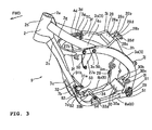
FIG. 3 is a perspective view showing a main frame and its surroundings of the motorcycle according to the first embodiment. -
FIG. 4 is a side view showing the main frame and its surroundings of the motorcycle according to the first embodiment. -
FIG. 5 is a plan view showing the main frame and its surroundings of the motorcycle according to the first embodiment. -
FIG. 6 is a side view showing a head pipe structure of the motorcycle according to the first embodiment. -
FIG. 7 is a side view taken along the cutout line 100-100 inFIG. 4 . -
FIG. 8 is a side view taken along the cutout line 200-200 inFIG. 4 . -
FIG. 9 is a side view taken along the cutout line 300-300 inFIG. 4 . -
FIG. 10 is a side view taken along the cutout line 400-400 inFIG. 4 . -
FIG. 11 is a side view taken along the cutout line 500-500 inFIG. 4 . -
FIG. 12 is an enlarged left side view of an engine according to the first embodiment. -
FIG. 13 is a schematic side view of an engine structure according to the first embodiment. -
FIG. 14 is a partial sectional view taken along the cutout line XIV-XIV inFIG. 12 . -
FIG. 15 is a conceptual view showing positional relationships among a cylinder body, a crankshaft, and a gear change mechanism according to the embodiment. -
FIG. 16 is a conceptual view showing positional relationships among the cylinder body, the crankshaft, and the gear change mechanism in a first case where a cylinder is not offset. -
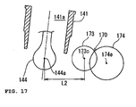
FIG. 17 is a conceptual view showing positional relationships among the cylinder body, the crankshaft, and the gear change mechanism in a second case where the cylinder is not offset. -
FIG. 18 is a conceptual view showing positional relationships among the cylinder body, the crankshaft, and the gear change mechanism in a third case where the cylinder is not offset. -
FIG. 19 is a schematic conceptual view showing the engine structure according to a second embodiment. -
FIG. 20 is a schematic side view showing the engine structure according to the second embodiment. -
FIG. 21 is a conceptual view showing structure showing engine main parts according to a modification. -
- 1: motorcycle (straddle-type vehicle)
- 15: engine
- 41: cylinder body
- 41a: cylinder
- 41b: axis of cylinder
- 42: cylinder head
- 44: crankshaft
- 44a: axis of crankshaft
- 46: piston
- 70: gear change mechanism
- 73: main shaft
- 73b: first shift gear group
- 74: drive shaft
- 74b: second shift gear group
- 80: starter motor
- 82: rotary shaft of starter motor
- 83: starter gear
- An example of the preferred embodiment of the invention will hereinafter be described by using a
motorcycle 1 shown inFIG. 1 as an example. However, a straddle-type vehicle according to the invention is not limited to the so-called off-road type motorcycle 1 shown inFIG. 1 . The "straddle-type vehicle" in the invention means a vehicle on which a rider straddles a seat. Therefore, the straddle-type vehicle according to the invention may be an All Terrain Vehicle (ATV) or the like. The straddle-type vehicle according to the invention may also be a motorcycle other than an off-road vehicle. More specifically, the straddle-type vehicle according to the invention may be a motorcycle in a narrow sense, a moped, a scooter, or the like. That is, the "motorcycle" in the invention includes a motorcycle in a narrow sense, a moped, a scooter, an off-road vehicle, and the like. In addition, the "motorcycle" in the invention includes a vehicle that has a plurality of wheels at least either in the front or in the rear thereof and that changes a traveling direction by tilting a vehicle body. - Forward, rear, left, and right directions in the following descriptions denote directions as viewed from the rider seated on a
seat 26. - As shown in
FIGs. 1 to 3 , themotorcycle 1 has abody frame 9. Thebody frame 9 includes ahead pipe 2, amain frame 3, atank rail 4, aseat rail 5, abackstay 6, adown frame 7, and alower frame 8. - The
head pipe 2 is disposed at the front end of thebody frame 9. Themain frame 3 is connected to thehead pipe 2. Themain frame 3 extends slightly downward to the rear from thehead pipe 2. Themain frame 3 is bent in the middle and extends approximately downward therefrom. - The
tank rail 4 is disposed between thehead pipe 2 and themain frame 3. A front end of thetank rail 4 is connected to thehead pipe 2. Meanwhile, a rear end of thetank rail 4 is connected to themain frame 3. Aresinous fuel tank 25 is disposed above thetank rail 4. Thefuel tank 25 is disposed such that it is held between aleft tank rail 4a and a right tank rail 4b, both of which constitute thetank rail 4. Theseat 26 is disposed behind thefuel tank 25. - The
seat rail 5 is connected to the middle of themain frame 3. Theseat rail 5 extends slightly upward to the rear from themain frame 3. A rear end of theseat rail 5 is connected to a rear end of themain frame 3 through thebackstay 6. - The down
frame 7 is connected to thehead pipe 2. The downframe 7 extends downward to the rear from thehead pipe 2 in a position below themain frame 3. A rear end of thedown frame 7 and the rear end of themain frame 3 are connected through thelower frame 8. - As shown in
FIG. 1 , a steering shaft, which is not shown, is rotatably inserted in thehead pipe 2.Handlebars 10 are mounted on top of the steering shaft. A pair offront forks 12 extending obliquely downward to the front is attached to the steering shaft. Afront wheel 13 is rotatably attached to lower ends of the pairedfront forks 12. Afront fender 14 is disposed above thefront wheel 13. Thefront wheel 13 is covered by thisfront fender 14 from above. - A
pivot shaft 19 is attached to the rear end of themain frame 3. Arear arm 20 is swingably attached to thepivot shaft 19. Arear wheel 21 is rotatably attached to a rear end of therear arm 20. Therear arm 20 is connected to an end of arear suspension 23 via acoupling member 24. The other end of therear suspension 23 is connected to themain frame 3. Shocks from the vertical swings of therear arm 20 are absorbed by thisrear suspension 23. - A
rear fender 22 is disposed above therear wheel 21. Therear wheel 21 is covered by thisrear fender 22 from above. - As shown in
FIG. 1 , anengine 15 is mounted in an area surrounded by themain frame 3, thedown frame 7, and thelower frame 8 in a side view. Aradiator 16 is disposed in front of and above theengine 15. Theradiator 16 is arranged to extend downward slightly to the rear. Theengine 15 is cooled down by a function of theradiator 16. An exhaust pipe 17 is connected to a rear portion of theengine 15. The exhaust pipe 17 extends rearward from theengine 15. The exhaust pipe 17 is connected to amuffler 18. - In this embodiment, the
head pipe 2 is made of aluminum. Thehead pipe 2 is formed by semi-solid die casting. By the way, semi-solid die casting is a method of forming a metal member by die casting metal that is a mixture of a liquid and solid phase. The utilization of semi-solid die casting can improve the strength of moldings when compared to the utilization of a regular casting method. - As shown in
FIG. 6 , thehead pipe 2 includes acylindrical section 2b and abody section 2c. Aninsertion hole 2a is formed in thecylindrical section 2b. Theinsertion hole 2a extends in a predetermined direction A. Thebody section 2c is located at the rear of thecylindrical section 2b. Thebody section 2c extends in a downward direction. - As shown in
FIGs. 2 and6 , aweld reinforcement 2d shown inFIG. 5 and aweld reinforcement 2e shown inFIG. 2 are formed in portions of thebody section 2c of thehead pipe 2 at the rear of thecylindrical section 2b. Theweld reinforcement 2d is formed to project from the left side of thehead pipe 2 to the rear. Theweld reinforcement 2e is formed to project from the right side of thehead pipe 2 to the rear. - A
weld part 2f shown inFIG. 6 and aweld part 2g shown inFIG. 2 are formed as frame parts in portions of thehead pipe 2 below theweld reinforcements - In this embodiment, the
weld reinforcements weld parts head pipe 2 are integrally formed by semi-solid die casting. - As shown in
FIG. 6 , arecess 2h is formed in a front portion of thebody section 2c. Therecess 2h opens in the direction A that theinsertion hole 2a extends. Therefore, as shown inFIG. 7 , thebody section 2c is formed to have a U-shaped cross section. - The
main frame 3 is made of aluminum as thehead pipe 2 is. Themain frame 3 is also formed by semi-solid die casting as thehead pipe 2 is. As shown inFIGs. 2 and3 , themain frame 3 includes aleft frame 3a located on the left side and aright frame 3b located on the right side. - As shown in
FIGs. 2 and5 , theleft frame 3a and theright frame 3b of themain frame 3 are arranged to extend rearward and to have predetermined spacing therebetween in a vehicle width direction in a plan view. Front ends of theleft frame 3a and theright frame 3b are respectively welded to theweld parts body section 2c of thehead pipe 2. Therefore, theleft frame 3a and theright frame 3b are formed in such a U-shape in cross section that they approach each other toward thebody section 2c of thehead pipe 2. - As shown in
FIGs. 2 and4 ,connections left frame 3a and theright frame 3b. Thetank rail 4 is welded to theconnections connections FIG. 2 are arranged to be fitted to aconnection 4c and aconnection 4d of thetank rail 4, respectively. Theconnections connection 4c and theconnection 4d. Theconnections recess 3e on an inner side of a portion thereof that is fitted to theconnections tank rail 4. - As shown in
FIGs. 2 and9 , portions of theleft frame 3a and theright frame 3b near the portions thereof to which thetank rail 4 is welded each have arecess 3f and has a U-shaped cross section. Aboss 3g is integrally formed on the inside of eachrecess 3f. As shown inFIG. 4 , asupport plate 27a and asupport plate 27b shown inFIG. 2 for supporting theengine 15 are fixed to thebosses 3g. Thebosses 3g and thesupport plate 27a as well as thebosses 3g and thesupport plate 27b are fixed byscrews 50. - In the embodiment, since the
main frame 3 is formed by semi-solid die casting, it is possible to integrally form therecesses 3e and thebosses 3g with themain frame 3. - As shown in
FIG. 2 ,bracket weld parts left frame 3a and of theright frame 3b in a longitudinal direction, respectively. As shown inFIG. 5 , thebracket weld parts FIGs. 2 and3 , arear suspension bracket 28 is welded to thebracket weld parts rear suspension 23 shown inFIG. 1 is supported by therear suspension bracket 28. - The
rear suspension bracket 28 includes across pipe 28a and twoattachments 28b. Thecross pipe 28a is formed by extrusion. The twoattachments 28b are integrally formed with thecross pipe 28a. A rear-suspension support hole 28c and a seat-rail support hole 28d are formed in each of theattachments 28b. - As shown in
FIG. 2 ,attachments left frame 3a at the rear of thebracket weld part 3h and at a portion of theright frame 3b at the rear of thebracket weld part 3i. Thebackstay 6 is attached to theattachments - Fixing
parts left frame 3a and theright frame 3b as shown inFIG. 1 . Thepivot shaft 19 is fixed to the fixingparts -
Footrest holding plates 29 are respectively fixed to a portion of theleft frame 3a, which is lower than the fixingpart 31, and to a portion of theright frame 3b, which is lower than the fixingpart 3m, with ascrew 51. A footrest, which is not shown, is held by thefootrest holding plate 29. - As shown in
FIG. 1 , acoupling member bracket 30 is welded to theleft frame 3a and theright frame 3b at their lower ends. Thecoupling members 24 are attached to thecoupling member bracket 30. Thecoupling member bracket 30 includes across pipe 30a and twoattachments 30b. Thecross pipe 30a is formed by extrusion. The twoattachments 30b are integrally formed with thecross pipe 30a. - A coupling-
member support hole 30c is formed in eachattachment 30b. - As shown in
FIGs. 3 and5 , theleft frame 3a and theright frame 3b are formed to extend inward to the front at the front of their lower ends. - The
tank rail 4 is made of aluminum. Thetank rail 4 is formed by extrusion. Thetank rail 4 includes theleft tank rail 4a located on the left side and the right tank rail 4b located on the right side. As shown inFIG. 10 , thetank rail 4 is made hollow. Thetank rail 4 includes awall 4g. An internal space of thetank rail 4 is divided into ahole 4e and ahole 4f by thewall 4g. At least one of thehole 4e and thehole 4f may be communicated with the outside. - As shown in
FIG. 2 , the front end of theleft tank rail 4a is welded to the upper left of thebody section 2c of thehead pipe 2 and theweld reinforcement 2d, which is shown inFIG. 5 . Theconnection 4c at the rear end of theleft tank rail 4a is welded to theconnection 3c of theleft frame 3a. The front end of the right tank rail 4b is welded to the upper right of thebody section 2c of thehead pipe 2 and theweld reinforcement 2e. Theconnection 4d at the rear end of the right tank rail 4b is welded to theconnection 3d of theright frame 3b. - The
seat rail 5 includes aleft rail 5a located on the left side, aright rail 5b located on the right side, and two reinforcing pipes 5c, 5d. Theleft rail 5a and theright rail 5b are connected by the two reinforcing pipes 5c, 5d. As shown inFIG. 3 , front ends of theleft rail 5a and theright rail 5b are fixed in the seat-rail support holes 28d in theattachments 28b of therear suspension bracket 28. - The
backstay 6 includes aleft stay 6a located on the left side and aright stay 6b located on the right side. Upper ends of theleft stay 6a and theright stay 6b are welded to theleft rail 5a and theright rail 5b, respectively. Lower ends of theleft stay 6a and theright stay 6b are attached to theattachment 3j on theleft frame 3a and theattachment 3k on theright frame 3b, respectively. - The down
frame 7 is made of aluminum. The downframe 7 is made by forging. As shown inFIG. 4 , a rear surface of thedown frame 7 is welded to thehead pipe 2. As shown inFIG. 7 , arecess 7a is formed in a part of thedown frame 7 to which thehead pipe 2 is welded. The part of thedown frame 7 to which thehead pipe 2 is welded has a U-shaped cross section. - As shown in
FIG. 2 , a lower part of thedown frame 7 is bifurcated into aleft frame 7b extending downward to the left and aright frame 7c extending downward to the right.Recesses left frame 7b and theright frame 7c. As shown inFIGs. 2 and11 ,support plates recesses FIGs. 2 and4 , asupport bar 32 for supporting theengine 15 is fixed to thesupport plates screws 53. - The
lower frame 8 is made of aluminum. Thelower frame 8 is formed by extrusion. Thelower frame 8 includes a leftlower frame 8a located on the left side and a rightlower frame 8b located on the right side. Front ends of the leftlower frame 8a and the rightlower frame 8b are welded to lower ends of theleft frame 7b and theright frame 7c, respectively. As shown inFIG. 3 ,support plates lower frame 8a and the rightlower frame 8b. Asupport bar 34 for supporting theengine 15 is fixed to thesupport plates screws 54. Rear ends of the leftlower frame 8a and the rightlower frame 8b are welded to front portions of lower ends of theleft frame 3a and theright frame 3b, respectively. - Next, the structure of the
engine unit 15 will be described with reference toFIGs. 12 to 14 . In this embodiment, theengine 15 is a water-cooled single-cylinder engine. However, the invention is not limited to this construction. Theengine 15 may be an in-line multi-cylinder engine. In addition, theengine 15 may be an air-cooled engine. The in-line multi-cylinder engine includes an in-line two cylinder engine. - As shown in
FIGs. 12 and13 , theengine 15 includes acrankcase 40, acylinder body 41, acylinder head 42, ahead cover 43 attached to an end of thecylinder head 42, agear change mechanism 70, and anoil pump 69. - As shown in
FIGs. 13 and14 , acrankshaft 44 extending in a vehicle width direction is housed in thecrankcase 40. A connectingrod 45 is attached to thecrankshaft 44. Apiston 46 is attached to an end of the connectingrod 45. - A
cylinder 41a in a generally cylindrical shape is formed in thecylinder body 41. Thepiston 46 is housed in thiscylinder 41a. Thecylinder body 41 is attached to a front half of thecrankcase 40. More specifically, as shown inFIG. 13 , thecylinder body 41 is attached to thecrankcase 40 in a manner that a lower portion of thecylinder body 41 is located inside thecrankcase 40. Therefore, thecylinder 41a extends into thecrankcase 40. - In detail, the
cylinder body 41 is attached to thecrankcase 40 in a manner that thecylinder 41a inclines rearward to the side of thegear change mechanism 70, which will be described later. More specifically, anaxis 41b of thecylinder 41a extends upward obliquely to the rear from thecrankshaft 44 side. Theaxis 41b of thecylinder 41a passes through in front of anaxis 44a of thecrankshaft 44 when viewed from a direction that thecrankshaft 44 extends. In other words, theaxis 41b of thecylinder 41a is located in front of astraight line 44b that passes through theaxis 44a of thecrankshaft 44 and is parallel to theaxis 41b. A direction in which thecrankshaft 44 extends is the same as the vehicle width direction. - As described above, the
axis 41b of thecylinder 41a passes through in front of theaxis 44a of thecrankshaft 44 when viewed from the direction in which thecrankshaft 44 extends. In this embodiment, to dispose a cylinder in such a manner is called to "offset the cylinder". - The
cylinder head 42 is attached to an end of thecylinder body 41. Avalve mechanism 47 is housed in thecylinder head 42. Thevalve mechanism 47 includes anintake valve 57, anexhaust valve 59, anintake camshaft 48, and anexhaust camshaft 49. Theintake valve 57 is driven by theintake camshaft 48. Theintake valve 57 opens and closes anintake port 58. Theexhaust valve 59 is driven by theexhaust camshaft 49. Theexhaust valve 59 opens and closes anexhaust port 60. - A
throttle body 61 is attached to theintake port 58. Air and fuel are supplied to acombustion chamber 62 from thisthrottle body 61 via theintake port 58. Meanwhile, anexhaust pipe 56 is connected to theexhaust port 60. Exhaust gas in thecombustion chamber 62 is discharged to the outside through theexhaust port 60 and theexhaust pipe 56. - The
gear change mechanism 70 is housed in thecrankcase 40. As shown inFIG. 14 , thegear change mechanism 70 includes atransmission 71 and amulti-plate clutch 72. Thetransmission 71 includes amain shaft 73 as an input shaft and adrive shaft 74 as an output shaft. - The clutch 72 is attached to a right end of the
main shaft 73. The clutch 72 includes aninner element 72a, anouter element 72b, and aplate group 72c. Theplate group 72c includes a plurality of clutch plates and a plurality of friction plates. The clutch plates and the friction plates are alternately located. Either the plural clutch plates or the plural friction plates are unable to rotate with respect to theinner element 72a, and the other plates are unable to rotate with respect to theouter element 72b. - The
plate group 72c is located between theinner element 72a and theouter element 72b. The plural plates constituting theplate group 72c are brought into contact with each other by pressurizing for rotation transmission between theinner element 72a and theouter element 72b. Theouter element 72b is rotatable with respect to themain shaft 73. Agear 72d is fixed to theouter element 72b. Thegear 72d meshes with agear 44c provided on thecrankshaft 44. Therefore, theouter element 72b rotates along with the rotation of thecrankshaft 44. On the other hand, theinner element 72a is attached to themain shaft 73 in a manner that it is unable to rotate with respect to themain shaft 73. Therefore, once the clutch 72 is engaged, theinner element 72a and themain shaft 73 rotate together with theouter element 72b. - The
main shaft 73 includes amain shaft body 73a and a firstshift gear group 73b. Meanwhile, thedrive shaft 74 includes adrive shaft body 74a and a secondshift gear group 74b. The firstshift gear group 73b and the secondshift gear group 74b mesh with each other. Ashift gear pair 75 is composed of the firstshift gear group 73b and the secondshift gear group 74b. The rotation of themain shaft 73 is transmitted to thedrive shaft 74 by theshift gear pair 75 in various change gear ratios. - A
sprocket 74c is provided on the left end of thedrive shaft 74. A drive chain, which is not shown, as a power transmission means to therear wheel 21 is wound around thissprocket 74c. Accordingly, the rotation of thedrive shaft 74 is transmitted to therear wheel 21. - A
gear 74d is formed at the right end of thedrive shaft 74. Thegear 74d meshes with a one-way gear 76a provided on akick shaft 76. Also, akick pedal 77 is attached to thekick shaft 76. Therefore, when thekick pedal 77 is operated by the rider, the rotation of thekick shaft 76 is transmitted to thecrankshaft 44 via thedrive shaft 74, themain shaft 73, and the clutch 72. - Next, the arrangement of each constructional member of the
engine 15 will be described in detail with reference toFIG. 13 . - The
gear change mechanism 70 is located behind theaxis 44a of thecrankshaft 44. Thegear change mechanism 70 is located further behind the lower end of thecylinder body 41. The upper end of themain shaft 73 is positioned higher than theaxis 44a of thecrankshaft 44. The upper end of themain shaft 73 is positioned higher than the lower end of thecylinder body 41. In other words, the lower end of thecylinder body 41 is positioned lower than the upper end of themain shaft 73. - An
axis 73c of themain shaft 73 is located generally right behind theaxis 44a of thecrankshaft 44. Strictly speaking, theaxis 73c of themain shaft 73 is located slightly higher than theaxis 44a of thecrankshaft 44. Theaxis 73c of themain shaft 73 is located above a straight line L passing through theaxis 44a of thecrankshaft 44 and anaxis 74e of thedrive shaft 74. - As described above, the
cylinder 41a is inclined rearward, and thecylinder 41a is offset in this embodiment. More specifically, thecylinder 41a is disposed in a manner that theaxis 41b of thecylinder 41a extends upward to the rear. At the same time, thecylinder 41a is disposed in a manner that theaxis 41b of thecylinder 41a passes through in front of theaxis 44a of thecrankshaft 44 when viewed from the direction that thecrankshaft 44 extends. Therefore, it is possible to concentrate the mass in theengine 15. - Effects of the above will be hereinafter described in detail with reference to
FIGs. 15 to 18 . -
FIG. 15 is a conceptual view showing positional relationships among thecylinder body 41, thecrankshaft 44, and thegear change mechanism 70.FIG. 16 is a conceptual view showing positional relationships among acylinder body 141, acrankshaft 144, and agear change mechanism 170 when acylinder 141a is not offset. As shown inFIG. 16 , when thecylinder 141a is not offset, the rearward inclination of thecylinder 141a tends to shorten a distance between thecylinder body 141 and thegear change mechanism 170. This may cause thecylinder body 141 to interfere with thegear change mechanism 170 in location wise. Therefore, it is difficult to sufficiently incline thecylinder 141a rearward. As a result, it is difficult to sufficiently concentrate the mass. - For instance, if it is attempted to sufficiently incline the cylinder rearward without offsetting the cylinder, the location of the
gear change mechanism 170 needs to be changed. More specifically, as shown inFIG. 17 , anaxis 173c of amain shaft 173 needs to be located away at the back of anaxis 144a of thecrankshaft 144. Or, theaxis 173c of themain shaft 173 needs to be located relatively lower as shown inFIG. 18 . - For example, as shown in
FIG. 17 , if theaxis 173c of themain shaft 173 is disposed away at the back of theaxis 144a of thecrankshaft 144, a distance L2 between theaxis 173c and theaxis 144a becomes longer than a distance L1 between theaxis 73c and theaxis 44a, which is shown inFIG. 15 . Therefore, thecrankshaft 144 and thegear change mechanism 170 as heavyweight objects end up being located away from each other. Consequently, the mass tends to be dispersed. - Also, for example, as shown in
FIG. 18 , when theaxis 173c of themain shaft 173 is disposed relatively lower, the distance between thecrankshaft 44 and themain shaft 73 does not become longer. However, a distance H2 between an upper end of thecylinder body 141 and a lower end of thegear change mechanism 170 becomes longer than a distance H1 between the upper end of thecylinder body 41 and the lower end of thegear change mechanism 70, which is shown inFIG. 15 . Consequently, the distance between thegear change mechanism 170 and the cylinder headbecomes longer. Therefore, the mass tends to be dispersed. - As described above, it is difficult to concentrate the mass in the
engine 15 merely with the rearward inclination of thecylinder 41a. In addition, theengine 15 tends to be enlarged in order to avoid positional interference between thecylinder 41a and thegear change mechanism 170. - On the contrary, as shown in
FIG. 15 , thecylinder 41a is inclined rearward while thecylinder 41a is offset in this embodiment. This makes thecylinder body 41 and thegear change mechanism 70 less likely to interfere with each other in location-wise even when thecylinder 41a is inclined rearward. Therefore, as shown inFIGs. 12 and13 , thecylinder head 42, which is attached to the upper end of thecylinder body 41, can be disposed as close to thegear change mechanism 70 as possible. Accordingly, thecylinder head 42, thecrankshaft 44, and thegear change mechanism 70 can be disposed in the proximity of each other. As a result, it is possible to concentrate the mass in theengine 15. - In addition, since the
cylinder 41a is offset, it is possible to obtain the following three merits. The first merit is that side thrust and piston slap can be reduced since a motion direction of thepiston 46a in an expansion stroke can be set relatively parallel to the connectingrod 45a. The second merit is that it is possible to shorten the compression time while extending the expansion time. The thirdmerit is that the process volume is increased. Therefore, the offset of thecylinder 41a allows a decrease in a diameter of thecylinder 41a if the engine displacement remains the same. Consequently, reduction in size and weight of theengine 15 is possible. - The offset amount, that is, a distance W between the
straight line 44b and thestraight line 41b shown inFIG. 13 is not particularly limited; however, it is preferably between 1 and 30 mm. It is more preferably between 5 and 20 mm and is further more preferably between 5 and 15 mm. - The preferable offset amount from a viewpoint of decreasing the side thrust varies in accordance with speed of the
engine 15. More specifically, when the speed of theengine 15 is relatively low such as 6000 rpm or less, it is preferable that the offset amount be large. On the other hand, when the speed of theengine 15 is relatively high, it is preferable that the offset amount be small. Therefore, the invention with which thecylinder 41b is offset is particularly useful for an engine whose performance in a lower speed range is emphasized and for a vehicle provided with the same. From the above viewpoint, it is especially useful for off-road vehicles and ATVs. - Also, since there is no need to move the arranged position of the
gear change mechanism 70 rearward or downward, the enlargement of the engine can be prevented.
In addition, the fuel efficiency can be improved by the offset. - The center of gravity of the
motorcycle 1 can be shifted to the rear side with the rearward inclination of thecylinder 41a. Consequently, load distribution on thefront wheel 13 decreases. Therefore, the invention is especially useful for a vehicle whose load distribution on thefront wheel 13 is preferably decreased. More specifically, it is especially useful for off-road vehicles and the like. - As shown in
FIGs. 13 and15 , in this embodiment, the lower end of thecylinder body 41 is located lower than the upper end of thegear change mechanism 70. Therefore, it is possible to decrease the distance between thecylinder head 42, which is attached to the upper end of thecylinder body 41, and thegear change mechanism 70 in a vertical direction. Accordingly, further mass concentration can be realized. - When the lower end of the
cylinder body 41 is located lower than the upper end of thegear change mechanism 70, positional interference between thegear change mechanism 70 and thecylinder body 41 becomes more likely to occur. Therefore, when the lower end of thecylinder body 41 is located lower than the upper end of thegear change mechanism 70, the offset of thecylinder 41a is especially effective. - As shown in
FIGs. 13 and15 , in this embodiment, the upper end of themain shaft 73 is located higher than theaxis 44a of thecrankshaft 44. Therefore, for example, comparing to the case where theaxis 44a of thecrankshaft 44 is lower than the upper end of themain shaft 73, it is possible to shorten the distance between thecylinder head 42 and thegear change mechanism 70. Consequently, further mass concentration can be realized. - As shown in
FIG. 13 , theaxis 73c of themain shaft 73 is located above the straight line L passing through theaxis 44a of thecrankshaft 44 and theaxis 74e of thedrive shaft 74. Therefore, for example, comparing to the case where theaxis 73c of themain shaft 73 is located on the straight line L, it is possible to shorten the distance between thedrive shaft 74 and thecrankshaft 44. Accordingly, further mass concentration can be possible, and reduction in size of theengine 15 in a longitudinal direction can also be possible. - This embodiment describes a case that the
axis 73c of themain shaft 73 is located above the straight line L; however, theaxis 73c of themain shaft 73 may be located below the straight line L. The above effect can be obtained also in such a case. In other words, it is preferable that theaxis 73c of themain shaft 73 be not located on the straight line L. - As described above, the
main frame 3 and thetank rail 4 are provided in this embodiment. Themain frame 3 is directly connected to thehead pipe 2. Themain frame 3 supports therear arm 20 to which therear wheel 21 is attached. The rear end of thetank rail 4 is connected to themain frame 3. Therefore, it is possible to connect themain frame 3, which supports therear arm 20 to which therear wheel 21 is attached, to thehead pipe 2. In addition to this, the connection between thehead pipe 2 and themain frame 3 can be reinforced. Therefore, it is possible to reinforce the connection between themain frame 3 for supporting therear arm 20 and thehead pipe 2 and to suppress an increase in the number of components of thebody frame 9. - In this embodiment, the
head pipe 2 is formed to extend rearward. Thehead pipe 2 is formed to include theweld parts main frame 3 is connected. Therefore, it is possible to easily and directly connect themain frame 3 to theweld parts head pipe 2. - Also, in this embodiment, the
bosses 3g for supporting theengine 15 are integrally formed with themain frame 3. Therefore, comparing to the case where thebosses 3g for supporting theengine 15 are separately formed from themain frame 3, it is possible to prevent an increase in the number of components for supporting theengine 15. - In this embodiment, the
head pipe 2 is provided with theinsertion hole 2a in which thesteering shaft 11 is inserted and therecess 2h opening in the direction along the direction A in which theinsertion hole 2a extends. Therefore, thehead pipe 2 having therecess 2h can be easily formed using dies by semi-solid die casting by setting a direction in which the die is pulled out to the direction that theinsertion hole 2a extends. - In this embodiment, the
left frame 3a and theright frame 3b of themain frame 3 are arranged to extend rearward while making the predetermined spacing therebetween in a vehicle width direction in a plan view. In addition, theleft frame 3a and theright frame 3b are arranged to assume such a U-shape that they approach each other toward thebody section 2c of thehead pipe 2. Therefore, it is possible to improve rigidity of thebody frame 9 in a planar direction. - In this embodiment, the
recess 3e is formed in each of theconnections main frame 3. More specifically, therecess 3e is formed inside the portion of each of theconnections tank rail 4. Therefore, it is possible to reduce the weight of themain frame 3. - In this embodiment, the
main frame 3 and thehead pipe 2 are formed by semi-solid die casting. Therefore, it is possible to reduce sizes and weights of themain frame 3 and thehead pipe 2 in comparison with a case where themain frame 3 and thehead pipe 2 are formed by forging or regular die casting. - Meanwhile, parts made by forging are less flexible and less accurate in shape than those made by semi-solid die casting. Therefore, when the
main frame 3 and thehead pipe 2 are formed by forging, it is difficult to form themain frame 3 and thehead pipe 2 in a shape of a recess (U-shape) or in a shape with which predetermined strength can be secured. It is necessary to thicken themain frame 3 and thehead pipe 2 if they are made by forging. As a result, themain frame 3 and thehead pipe 2 tend to be enlarged, and thus the weights of themain frame 3 and thehead pipe 2 tend to increase. - If the
main frame 3 and thehead pipe 2 are formed by common die casting, they become less strong than those formed by semi-solid die casting. Consequently, it is necessary to thicken themain frame 3 and thehead pipe 2 in order to secure the predetermined strength thereof. Therefore, there is a tendency that the size of thehead pipe 2 as well as the weight thereof increases. - In the above embodiment, one example of the preferred embodiments in which the invention is embodied is described by raising the
motorcycle 1 as an example. However, to concentrate the mass in theengine 15 is an object to be achieved common to vehicle engines. Therefore, the engine of the invention may be mounted in a vehicle other than a motorcycle. - It has to be noted, however, that a space for mounting the
engine 15 is smaller in a straddle-type vehicle than in a four-wheeled automobile. In addition, the relatively higher motion performance is requested. In a motorcycle, a space for mounting theengine 15 is especially small. Therefore, the invention with which the mass can be concentrated is useful for straddle-type vehicles, and especially for motorcycles. Since higher motion performance can be realized with the mass concentration, it is especially useful for off-road vehicles and ATVs. - The above first embodiment describes a case that only the
kick pedal 77 shown inFIG. 14 is provided as a starter of theengine 15. However, the invention is not limited to this construction. For instance, astarter motor 80 may be disposed as a starter either with thekick pedal 77 or without thekick pedal 77. -
FIG. 19 is a schematic conceptual view showing structure of anengine 15a according to the second embodiment.FIG. 20 is a schematic side view showing the structure of theengine 15a according to the second embodiment. Descriptions will hereinafter be made of theengine 15a according to the second embodiment with reference toFIGs. 19 and20 . - In the following descriptions, components having substantially the same mechanism as those in the above first embodiment are designated by the same reference numerals, and their description is omitted.
- As shown in
FIG. 19 , a one-way gear 44d is provided on the left end of thecrankshaft 44 in this embodiment. Thisgear 44d meshes with astarter gear 83 through anidle gear 81. Thestarter gear 83 is attached to arotary shaft 82 of thestarter motor 80. Therefore, when therotary shaft 82 of thestarter motor 80 rotates, rotation thereof is transmitted to thecrankshaft 44 via thestarter gear 83, theidle gear 81, and the one-way gear 44d. - Next, the arrangement of each constructional member of the
engine 15 of this embodiment will be described with reference toFIG. 20 . As shown inFIG. 20 , thestarter motor 80 is located above thegear change mechanism 70 and behind thecylinder body 41. In detail, anaxis 82a of therotary shaft 82 of thestarter motor 80 is located above thegear change mechanism 70 and behind thecylinder body 41. In more detail, thestarter motor 80 is located above themain shaft 73 in this embodiment. Theaxis 82a is located forward of the rear end of thegear change mechanism 70. Theaxis 82a is located forward of theaxis 74e of thedrive shaft 74. - As described above, the center of gravity of the
engine 15 can be brought closer to thestarter motor 80 by disposing thestarter motor 80 above thegear change mechanism 70 and behind thecylinder body 41. Therefore, it is possible to further concentrate the mass in theengine 15. - It is preferable that the
axis 82a of therotary shaft 82 of thestarter motor 80 be located within an area surrounded by the straight line L, thestraight line 44b, and a tangent L2 to an outline of thedrive shaft 74 at the rear end of thedrive shaft 74 on the straight line L. Then, it is possible to further concentrate the mass in theengine 15.
By the way, thestarter motor 80 is located outside thecrankcase 40. In detail, it is located on top of thecrankcase 40. One end of therotary shaft 82 of thestarter motor 80 is inserted inside thecrankcase 40 and is connected with thestarter gear 83 located inside thecrankcase 40. - In the above embodiment, the
engine 15 is described by raising a single-cylinder engine as an example. However, theengine 15 may be an in-line multi-cylinder engine as shown inFIG. 21 . - More specifically, two connecting
rods crankshaft 44 inFIG. 21 . Apiston 46a is attached to an end of the connectingrod 45a. Thepiston 46a is housed in acylinder 41d formed in acylinder body 41c. Apiston 46b is attached to an end of the connectingrod 45b. Thepiston 46b is housed in acylinder 41e formed in acylinder body 41f. - Now, it should be understood that the embodiments disclosed herein are given as mere illustrations in all respects, but not given to impose any limitation. The scope of the invention is not defined by the descriptions of the above embodiments, but defined by the scope of the claims, and includes all modifications that fall within the meaning and scope equivalent to the scope of the claims.
- In the above embodiments, the example in which the main frame is directly connected to the head pipe is described. However, the invention is not limited thereto. The weld part as a frame fixing part may be separately formed from the head pipe, and the main frame may be connected to the head pipe via the weld part.
- In the above embodiments, the example in which the head pipe and the main frame are formed by semi-solid die casting is described; however, the invention is not limited to this configuration. The head pipe and the main frame may be formed by a method other than semi-solid die casting. For example, the head pipe and the main frame may be formed by forging or common die casting.
- In the above embodiment, the example in which the rear suspension bracket is composed of the cross pipe formed by extrusion and the attachments welded to the cross pipe has been described. However, the invention is not limited thereto. The rear suspension bracket may be formed by semi-solid die casting. This allows simultaneous forming of the cross pipe and the attachments.
- In the above embodiment, the example in which the head pipe and the main frame are formed to have a U-shape in cross section has been described; however, the invention is not limited thereto. The head pipe and the main frame may be formed to not have a U-shape in cross section.
- In the above embodiment, the example in which the fuel tank is supported by the tank rail as the second frame connected to the head pipe and the main frame has been described. However, the invention is not limited thereto. The fuel tank may be supported by the main frame as the first frame.
Claims (6)
- An single-cylinder or in-line multi-cylinder engine comprising:a crankshaft;a piston connected to the crankshaft;a cylinder body in which a cylinder housing the piston is formed;a cylinder head mounted on an end of the cylinder body; anda gear change mechanism located behind the crankshaft, whereinan axis of the cylinder extends upward obliquely to the rear from the crankshaft side and passes through in front of an axis of the crankshaft when viewed from a direction in which the crankshaft extends.
- The engine according to Claim 1, wherein
a lower end of the cylinder body is positioned lower than an upper end of the gear change mechanism. - The engine according to Claim 1, wherein
the gear change mechanism includes:a main shaft to which rotation of the crankshaft is input having a first shift gear group; anda drive shaft located behind the main shaft and having a second shift gear group meshed with the first shift gear group, andan upper end of the main shaft is located higher than the axis of the crankshaft. - The engine according to Claim 1, wherein
the gear change mechanism includes:a main shaft to which rotation of the crankshaft is input having a first shift gear group; anda drive shaft located behind the main shaft and having a second shift gear group meshed with the first shift gear group, andan axis of the main shaft is located above or below a straight line passing through the axis of the crankshaft and the drive shaft. - The engine according to Claim 1 further comprising:a starter motor having a rotary shaft and a starter gear attached to the rotary shaft and directly or indirectly meshed with the crankshaft, whereinan axis of the rotary shaft is located above the gear change mechanism and behind the cylinder body.
- A straddle-type vehicle comprising the engine according to Claim 1.
Applications Claiming Priority (2)
| Application Number | Priority Date | Filing Date | Title |
|---|---|---|---|
| JP2006308757 | 2006-11-15 | ||
| PCT/JP2007/072205 WO2008059932A1 (en) | 2006-11-15 | 2007-11-15 | Engine with single cylinder or juxtaposed multiple cylinders and saddle ride-type vehicle with the same |
Publications (3)
| Publication Number | Publication Date |
|---|---|
| EP2082954A1 true EP2082954A1 (en) | 2009-07-29 |
| EP2082954A4 EP2082954A4 (en) | 2013-11-20 |
| EP2082954B1 EP2082954B1 (en) | 2019-10-02 |
Family
ID=39401735
Family Applications (1)
| Application Number | Title | Priority Date | Filing Date |
|---|---|---|---|
| EP07831935.7A Active EP2082954B1 (en) | 2006-11-15 | 2007-11-15 | Engine with single cylinder or juxtaposed multiple cylinders and saddle ride-type vehicle with the same |
Country Status (4)
| Country | Link |
|---|---|
| US (2) | US8245672B2 (en) |
| EP (1) | EP2082954B1 (en) |
| JP (2) | JP2008143511A (en) |
| WO (2) | WO2008059932A1 (en) |
Families Citing this family (20)
| Publication number | Priority date | Publication date | Assignee | Title |
|---|---|---|---|---|
| US20090272593A1 (en) * | 2008-04-30 | 2009-11-05 | Christopher Myers | Motorcycle Frame Arrangement |
| US8403100B2 (en) * | 2008-08-08 | 2013-03-26 | Yamaha Motor Co., Ltd. | Vehicle and vehicle exhaust pipe |
| JP5330052B2 (en) * | 2009-03-27 | 2013-10-30 | 本田技研工業株式会社 | Motorcycle |
| JP5372571B2 (en) * | 2009-03-30 | 2013-12-18 | 本田技研工業株式会社 | Motorcycle |
| JP5323883B2 (en) * | 2011-04-14 | 2013-10-23 | 本田技研工業株式会社 | Motorcycle internal combustion engine |
| JP5853618B2 (en) * | 2011-11-11 | 2016-02-09 | スズキ株式会社 | Frame structure of saddle riding type vehicle |
| JP2014065465A (en) * | 2012-09-27 | 2014-04-17 | Honda Motor Co Ltd | Internal combustion engine for motorcycle |
| JP5750430B2 (en) * | 2012-12-26 | 2015-07-22 | 本田技研工業株式会社 | Casing structure of in-vehicle internal combustion engine |
| JP6151987B2 (en) * | 2013-06-26 | 2017-06-21 | 本田技研工業株式会社 | Engine support structure for saddle-ride type vehicles |
| JP6204089B2 (en) * | 2013-07-03 | 2017-09-27 | 川崎重工業株式会社 | Motorcycle body frame |
| JP6140556B2 (en) * | 2013-07-10 | 2017-05-31 | 本田技研工業株式会社 | Motorcycle |
| JP6113027B2 (en) * | 2013-09-03 | 2017-04-12 | 本田技研工業株式会社 | Saddle riding type vehicle |
| JP6704300B2 (en) * | 2016-06-15 | 2020-06-03 | 川崎重工業株式会社 | Motorcycle |
| WO2018029736A1 (en) * | 2016-08-08 | 2018-02-15 | 本田技研工業株式会社 | Vehicle |
| CN206012323U (en) * | 2016-09-20 | 2017-03-15 | 浙江奇野车业有限公司 | A kind of car body |
| JP2018086907A (en) | 2016-11-28 | 2018-06-07 | ヤマハ発動機株式会社 | Saddle riding vehicle |
| JP6695368B2 (en) * | 2018-02-05 | 2020-05-20 | 本田技研工業株式会社 | Body frame reinforcement structure for saddle type vehicles |
| JP6806745B2 (en) | 2018-08-30 | 2021-01-06 | 本田技研工業株式会社 | Body frame structure of saddle-riding vehicle |
| JP7096134B2 (en) * | 2018-10-23 | 2022-07-05 | カワサキモータース株式会社 | Saddle-type vehicle |
| JP7234045B2 (en) * | 2019-06-14 | 2023-03-07 | 本田技研工業株式会社 | Body frame of saddle type vehicle |
Family Cites Families (35)
| Publication number | Priority date | Publication date | Assignee | Title |
|---|---|---|---|---|
| JPS494181B1 (en) * | 1970-11-06 | 1974-01-30 | ||
| JPS56118522A (en) * | 1980-02-23 | 1981-09-17 | Yamaha Motor Co Ltd | V type engine for motorcycle |
| US4798254A (en) * | 1987-03-10 | 1989-01-17 | National Research Development Corporation | Components in or for self-powered vehicles |
| US4945866A (en) * | 1987-03-26 | 1990-08-07 | Chabot Jr Bertin R | Altered piston timing engine |
| JPH0231990A (en) * | 1988-07-20 | 1990-02-01 | Suzuki Motor Co Ltd | Frame of motorcycle |
| JPH06317178A (en) * | 1990-04-19 | 1994-11-15 | Makoto Matsumoto | Internal combustion engine |
| US5109943A (en) | 1990-07-13 | 1992-05-05 | Crenshaw Rodney D | Motorcycle engine stabilizer |
| US5186127A (en) * | 1991-01-28 | 1993-02-16 | Lorenzo Cuatico | Internal combustion engine with offset connecting journal |
| JPH05278661A (en) * | 1992-04-03 | 1993-10-26 | Yamaha Motor Co Ltd | Motorcycle |
| JPH068873A (en) * | 1992-06-24 | 1994-01-18 | Suzuki Motor Corp | Motorcycle |
| JPH07195949A (en) * | 1993-12-29 | 1995-08-01 | Honda Motor Co Ltd | Power unit for saddle type vehicle |
| CN1121329C (en) | 1998-09-11 | 2003-09-17 | 本田技研工业株式会社 | Frame integrated fuel tank structure |
| JP3766580B2 (en) | 2000-03-31 | 2006-04-12 | 本田技研工業株式会社 | Manufacturing method of body frame for motorcycle |
| JP3907375B2 (en) | 2000-03-31 | 2007-04-18 | 本田技研工業株式会社 | Body frame for motorcycles |
| JP3867486B2 (en) | 2000-09-06 | 2007-01-10 | スズキ株式会社 | Motorcycle |
| JP3986760B2 (en) * | 2001-02-02 | 2007-10-03 | 本田技研工業株式会社 | Motorcycle engine |
| JP3990551B2 (en) | 2001-06-12 | 2007-10-17 | 本田技研工業株式会社 | Motorcycle frame structure |
| JP2003083161A (en) * | 2001-09-10 | 2003-03-19 | Honda Motor Co Ltd | V-type engine for motorcycles |
| DE60239223D1 (en) * | 2001-12-28 | 2011-03-31 | Yamaha Motor Co Ltd | VEHICLE CARRIER FRAME FOR MOTORCYCLE |
| US6612281B1 (en) * | 2002-03-12 | 2003-09-02 | Larry K. Martin | Piston/crankshaft assembly |
| GB2401592A (en) * | 2002-06-07 | 2004-11-17 | Brumby Corp Ltd | Motorcycle engine |
| JP4057384B2 (en) | 2002-09-26 | 2008-03-05 | 本田技研工業株式会社 | Engine mounting structure for low floor vehicles |
| JP4252816B2 (en) | 2003-02-20 | 2009-04-08 | 本田技研工業株式会社 | Motorcycle structure |
| JP4368596B2 (en) | 2003-02-26 | 2009-11-18 | 本田技研工業株式会社 | Body structure of motorcycle |
| JP2004299464A (en) | 2003-03-28 | 2004-10-28 | Yamaha Motor Co Ltd | Motorcycle body frame |
| US7588009B2 (en) * | 2003-06-23 | 2009-09-15 | Honda Motor Co., Ltd. | Layout structure of a fuel injection device in a motor cycle |
| JP4233936B2 (en) * | 2003-06-23 | 2009-03-04 | 本田技研工業株式会社 | Engine starter |
| JP4514712B2 (en) * | 2003-07-10 | 2010-07-28 | ヤマハ発動機株式会社 | Engine for saddle-ride type vehicle |
| JP2007022098A (en) * | 2003-10-23 | 2007-02-01 | Yamaha Motor Co Ltd | Saddle-type vehicle engine and straddle-type vehicle equipped with the same |
| JP4570883B2 (en) * | 2004-02-05 | 2010-10-27 | 川崎重工業株式会社 | Body frame for motorcycles |
| JP2006015837A (en) * | 2004-06-30 | 2006-01-19 | Yamaha Motor Co Ltd | Motorcycle |
| JP4458991B2 (en) * | 2004-09-03 | 2010-04-28 | 本田技研工業株式会社 | Scooter type motorcycle |
| US7637345B2 (en) | 2004-12-24 | 2009-12-29 | Kawasaki Jukogyo Kabushiki Kaisha | Frame of motorcycle and engine bracket |
| JP4853900B2 (en) | 2006-02-23 | 2012-01-11 | 本田技研工業株式会社 | Body frame structure for motorcycles |
| JP2007307944A (en) | 2006-05-16 | 2007-11-29 | Honda Motor Co Ltd | Motorcycle frame structure |
-
2007
- 2007-10-19 JP JP2007272716A patent/JP2008143511A/en active Pending
- 2007-11-15 EP EP07831935.7A patent/EP2082954B1/en active Active
- 2007-11-15 JP JP2008544199A patent/JP4967153B2/en active Active
- 2007-11-15 WO PCT/JP2007/072205 patent/WO2008059932A1/en not_active Ceased
- 2007-11-15 WO PCT/JP2007/072206 patent/WO2008059933A1/en not_active Ceased
- 2007-11-15 US US12/447,072 patent/US8245672B2/en active Active
-
2009
- 2009-05-15 US US12/466,956 patent/US9297300B2/en not_active Expired - Fee Related
Also Published As
| Publication number | Publication date |
|---|---|
| US9297300B2 (en) | 2016-03-29 |
| US8245672B2 (en) | 2012-08-21 |
| EP2082954A4 (en) | 2013-11-20 |
| JP4967153B2 (en) | 2012-07-04 |
| US20090266637A1 (en) | 2009-10-29 |
| JP2008143511A (en) | 2008-06-26 |
| JPWO2008059932A1 (en) | 2010-03-04 |
| US20090320785A1 (en) | 2009-12-31 |
| WO2008059932A1 (en) | 2008-05-22 |
| WO2008059933A1 (en) | 2008-05-22 |
| EP2082954B1 (en) | 2019-10-02 |
Similar Documents
| Publication | Publication Date | Title |
|---|---|---|
| EP2082954B1 (en) | Engine with single cylinder or juxtaposed multiple cylinders and saddle ride-type vehicle with the same | |
| KR100557901B1 (en) | Engine mounting structure for low floor type vehicle | |
| US7694985B2 (en) | Reinforced motorcycle frame | |
| US7364001B2 (en) | Engine mounting structure for motorcycle | |
| TWI254686B (en) | Rear cushion mounting structure for low-chassis vehicle | |
| JP4899625B2 (en) | Saddle-type rough terrain vehicle | |
| EP2471704B1 (en) | Saddled vehicle | |
| JP5451287B2 (en) | Cylinder head cover structure for small vehicles | |
| EP2048073A2 (en) | Straddle-type vehicle | |
| JP2002227601A (en) | Motorcycle engine | |
| JP2010228736A (en) | Motorcycle | |
| JP3996251B2 (en) | Scooter type motorcycle | |
| US20100243366A1 (en) | Motorcycle Engine | |
| JP5706249B2 (en) | Electronic throttle arrangement structure for vehicles | |
| JP2002037174A (en) | Engine exhaust device support structure for motorcycles | |
| US8051739B2 (en) | Vehicle-use transmission manipulating device | |
| JP2004293348A (en) | Internal combustion engine | |
| JP2006044640A (en) | Saddle-type vehicle and rear arm mounting method | |
| JP2007030688A (en) | Rear cushion arrangement structure for motorcycles | |
| JP5255937B2 (en) | Body structure of saddle-ride type vehicle | |
| JP2009024555A (en) | Breather device for internal combustion engine | |
| WO2006003759A1 (en) | Two-wheeled motor vehicle | |
| JP5311650B2 (en) | Motorcycle | |
| CN102556238A (en) | Exhausting device of mount-type vehicle | |
| JP2010228739A (en) | Motorcycle |
Legal Events
| Date | Code | Title | Description |
|---|---|---|---|
| PUAI | Public reference made under article 153(3) epc to a published international application that has entered the european phase |
Free format text: ORIGINAL CODE: 0009012 |
|
| 17P | Request for examination filed |
Effective date: 20090506 |
|
| AK | Designated contracting states |
Kind code of ref document: A1 Designated state(s): AT BE BG CH CY CZ DE DK EE ES FI FR GB GR HU IE IS IT LI LT LU LV MC MT NL PL PT RO SE SI SK TR |
|
| DAX | Request for extension of the european patent (deleted) | ||
| A4 | Supplementary search report drawn up and despatched |
Effective date: 20131022 |
|
| RIC1 | Information provided on ipc code assigned before grant |
Ipc: F02B 61/02 20060101ALI20131016BHEP Ipc: B62K 11/04 20060101AFI20131016BHEP Ipc: B62M 7/04 20060101ALI20131016BHEP |
|
| 17Q | First examination report despatched |
Effective date: 20141010 |
|
| STAA | Information on the status of an ep patent application or granted ep patent |
Free format text: STATUS: EXAMINATION IS IN PROGRESS |
|
| REG | Reference to a national code |
Ref country code: DE Ref legal event code: R079 Ref document number: 602007059304 Country of ref document: DE Free format text: PREVIOUS MAIN CLASS: B62M0007020000 Ipc: F02B0061020000 |
|
| GRAP | Despatch of communication of intention to grant a patent |
Free format text: ORIGINAL CODE: EPIDOSNIGR1 |
|
| STAA | Information on the status of an ep patent application or granted ep patent |
Free format text: STATUS: GRANT OF PATENT IS INTENDED |
|
| RIC1 | Information provided on ipc code assigned before grant |
Ipc: F02B 61/02 20060101AFI20190522BHEP Ipc: B62K 19/32 20060101ALI20190522BHEP Ipc: B62K 11/04 20060101ALI20190522BHEP Ipc: F02F 7/00 20060101ALI20190522BHEP Ipc: B62K 19/28 20060101ALI20190522BHEP |
|
| INTG | Intention to grant announced |
Effective date: 20190624 |
|
| GRAS | Grant fee paid |
Free format text: ORIGINAL CODE: EPIDOSNIGR3 |
|
| GRAA | (expected) grant |
Free format text: ORIGINAL CODE: 0009210 |
|
| STAA | Information on the status of an ep patent application or granted ep patent |
Free format text: STATUS: THE PATENT HAS BEEN GRANTED |
|
| AK | Designated contracting states |
Kind code of ref document: B1 Designated state(s): AT BE BG CH CY CZ DE DK EE ES FI FR GB GR HU IE IS IT LI LT LU LV MC MT NL PL PT RO SE SI SK TR |
|
| REG | Reference to a national code |
Ref country code: GB Ref legal event code: FG4D |
|
| REG | Reference to a national code |
Ref country code: CH Ref legal event code: EP Ref country code: AT Ref legal event code: REF Ref document number: 1186411 Country of ref document: AT Kind code of ref document: T Effective date: 20191015 |
|
| REG | Reference to a national code |
Ref country code: DE Ref legal event code: R096 Ref document number: 602007059304 Country of ref document: DE |
|
| REG | Reference to a national code |
Ref country code: IE Ref legal event code: FG4D |
|
| REG | Reference to a national code |
Ref country code: NL Ref legal event code: MP Effective date: 20191002 |
|
| REG | Reference to a national code |
Ref country code: LT Ref legal event code: MG4D |
|
| REG | Reference to a national code |
Ref country code: AT Ref legal event code: MK05 Ref document number: 1186411 Country of ref document: AT Kind code of ref document: T Effective date: 20191002 |
|
| PG25 | Lapsed in a contracting state [announced via postgrant information from national office to epo] |
Ref country code: FI Free format text: LAPSE BECAUSE OF FAILURE TO SUBMIT A TRANSLATION OF THE DESCRIPTION OR TO PAY THE FEE WITHIN THE PRESCRIBED TIME-LIMIT Effective date: 20191002 Ref country code: BG Free format text: LAPSE BECAUSE OF FAILURE TO SUBMIT A TRANSLATION OF THE DESCRIPTION OR TO PAY THE FEE WITHIN THE PRESCRIBED TIME-LIMIT Effective date: 20200102 Ref country code: PT Free format text: LAPSE BECAUSE OF FAILURE TO SUBMIT A TRANSLATION OF THE DESCRIPTION OR TO PAY THE FEE WITHIN THE PRESCRIBED TIME-LIMIT Effective date: 20200203 Ref country code: GR Free format text: LAPSE BECAUSE OF FAILURE TO SUBMIT A TRANSLATION OF THE DESCRIPTION OR TO PAY THE FEE WITHIN THE PRESCRIBED TIME-LIMIT Effective date: 20200103 Ref country code: PL Free format text: LAPSE BECAUSE OF FAILURE TO SUBMIT A TRANSLATION OF THE DESCRIPTION OR TO PAY THE FEE WITHIN THE PRESCRIBED TIME-LIMIT Effective date: 20191002 Ref country code: AT Free format text: LAPSE BECAUSE OF FAILURE TO SUBMIT A TRANSLATION OF THE DESCRIPTION OR TO PAY THE FEE WITHIN THE PRESCRIBED TIME-LIMIT Effective date: 20191002 Ref country code: NL Free format text: LAPSE BECAUSE OF FAILURE TO SUBMIT A TRANSLATION OF THE DESCRIPTION OR TO PAY THE FEE WITHIN THE PRESCRIBED TIME-LIMIT Effective date: 20191002 Ref country code: LT Free format text: LAPSE BECAUSE OF FAILURE TO SUBMIT A TRANSLATION OF THE DESCRIPTION OR TO PAY THE FEE WITHIN THE PRESCRIBED TIME-LIMIT Effective date: 20191002 Ref country code: ES Free format text: LAPSE BECAUSE OF FAILURE TO SUBMIT A TRANSLATION OF THE DESCRIPTION OR TO PAY THE FEE WITHIN THE PRESCRIBED TIME-LIMIT Effective date: 20191002 Ref country code: SE Free format text: LAPSE BECAUSE OF FAILURE TO SUBMIT A TRANSLATION OF THE DESCRIPTION OR TO PAY THE FEE WITHIN THE PRESCRIBED TIME-LIMIT Effective date: 20191002 Ref country code: LV Free format text: LAPSE BECAUSE OF FAILURE TO SUBMIT A TRANSLATION OF THE DESCRIPTION OR TO PAY THE FEE WITHIN THE PRESCRIBED TIME-LIMIT Effective date: 20191002 |
|
| PG25 | Lapsed in a contracting state [announced via postgrant information from national office to epo] |
Ref country code: IS Free format text: LAPSE BECAUSE OF FAILURE TO SUBMIT A TRANSLATION OF THE DESCRIPTION OR TO PAY THE FEE WITHIN THE PRESCRIBED TIME-LIMIT Effective date: 20200224 Ref country code: CZ Free format text: LAPSE BECAUSE OF FAILURE TO SUBMIT A TRANSLATION OF THE DESCRIPTION OR TO PAY THE FEE WITHIN THE PRESCRIBED TIME-LIMIT Effective date: 20191002 |
|
| REG | Reference to a national code |
Ref country code: CH Ref legal event code: PL |
|
| REG | Reference to a national code |
Ref country code: DE Ref legal event code: R097 Ref document number: 602007059304 Country of ref document: DE |
|
| PG2D | Information on lapse in contracting state deleted |
Ref country code: IS |
|
| PG25 | Lapsed in a contracting state [announced via postgrant information from national office to epo] |
Ref country code: MC Free format text: LAPSE BECAUSE OF FAILURE TO SUBMIT A TRANSLATION OF THE DESCRIPTION OR TO PAY THE FEE WITHIN THE PRESCRIBED TIME-LIMIT Effective date: 20191002 Ref country code: LU Free format text: LAPSE BECAUSE OF NON-PAYMENT OF DUE FEES Effective date: 20191115 Ref country code: RO Free format text: LAPSE BECAUSE OF FAILURE TO SUBMIT A TRANSLATION OF THE DESCRIPTION OR TO PAY THE FEE WITHIN THE PRESCRIBED TIME-LIMIT Effective date: 20191002 Ref country code: DK Free format text: LAPSE BECAUSE OF FAILURE TO SUBMIT A TRANSLATION OF THE DESCRIPTION OR TO PAY THE FEE WITHIN THE PRESCRIBED TIME-LIMIT Effective date: 20191002 Ref country code: CH Free format text: LAPSE BECAUSE OF NON-PAYMENT OF DUE FEES Effective date: 20191130 Ref country code: LI Free format text: LAPSE BECAUSE OF NON-PAYMENT OF DUE FEES Effective date: 20191130 Ref country code: EE Free format text: LAPSE BECAUSE OF FAILURE TO SUBMIT A TRANSLATION OF THE DESCRIPTION OR TO PAY THE FEE WITHIN THE PRESCRIBED TIME-LIMIT Effective date: 20191002 Ref country code: IS Free format text: LAPSE BECAUSE OF FAILURE TO SUBMIT A TRANSLATION OF THE DESCRIPTION OR TO PAY THE FEE WITHIN THE PRESCRIBED TIME-LIMIT Effective date: 20200202 |
|
| PLBE | No opposition filed within time limit |
Free format text: ORIGINAL CODE: 0009261 |
|
| STAA | Information on the status of an ep patent application or granted ep patent |
Free format text: STATUS: NO OPPOSITION FILED WITHIN TIME LIMIT |
|
| REG | Reference to a national code |
Ref country code: BE Ref legal event code: MM Effective date: 20191130 |
|
| PG25 | Lapsed in a contracting state [announced via postgrant information from national office to epo] |
Ref country code: SK Free format text: LAPSE BECAUSE OF FAILURE TO SUBMIT A TRANSLATION OF THE DESCRIPTION OR TO PAY THE FEE WITHIN THE PRESCRIBED TIME-LIMIT Effective date: 20191002 Ref country code: IT Free format text: LAPSE BECAUSE OF FAILURE TO SUBMIT A TRANSLATION OF THE DESCRIPTION OR TO PAY THE FEE WITHIN THE PRESCRIBED TIME-LIMIT Effective date: 20191002 |
|
| 26N | No opposition filed |
Effective date: 20200703 |
|
| PG25 | Lapsed in a contracting state [announced via postgrant information from national office to epo] |
Ref country code: IE Free format text: LAPSE BECAUSE OF NON-PAYMENT OF DUE FEES Effective date: 20191115 |
|
| PG25 | Lapsed in a contracting state [announced via postgrant information from national office to epo] |
Ref country code: SI Free format text: LAPSE BECAUSE OF FAILURE TO SUBMIT A TRANSLATION OF THE DESCRIPTION OR TO PAY THE FEE WITHIN THE PRESCRIBED TIME-LIMIT Effective date: 20191002 Ref country code: BE Free format text: LAPSE BECAUSE OF NON-PAYMENT OF DUE FEES Effective date: 20191130 |
|
| PG25 | Lapsed in a contracting state [announced via postgrant information from national office to epo] |
Ref country code: CY Free format text: LAPSE BECAUSE OF FAILURE TO SUBMIT A TRANSLATION OF THE DESCRIPTION OR TO PAY THE FEE WITHIN THE PRESCRIBED TIME-LIMIT Effective date: 20191002 |
|
| PG25 | Lapsed in a contracting state [announced via postgrant information from national office to epo] |
Ref country code: MT Free format text: LAPSE BECAUSE OF FAILURE TO SUBMIT A TRANSLATION OF THE DESCRIPTION OR TO PAY THE FEE WITHIN THE PRESCRIBED TIME-LIMIT Effective date: 20191002 Ref country code: HU Free format text: LAPSE BECAUSE OF FAILURE TO SUBMIT A TRANSLATION OF THE DESCRIPTION OR TO PAY THE FEE WITHIN THE PRESCRIBED TIME-LIMIT; INVALID AB INITIO Effective date: 20071115 |
|
| PG25 | Lapsed in a contracting state [announced via postgrant information from national office to epo] |
Ref country code: TR Free format text: LAPSE BECAUSE OF FAILURE TO SUBMIT A TRANSLATION OF THE DESCRIPTION OR TO PAY THE FEE WITHIN THE PRESCRIBED TIME-LIMIT Effective date: 20191002 |
|
| P01 | Opt-out of the competence of the unified patent court (upc) registered |
Effective date: 20230527 |
|
| PGFP | Annual fee paid to national office [announced via postgrant information from national office to epo] |
Ref country code: DE Payment date: 20251119 Year of fee payment: 19 |
|
| PGFP | Annual fee paid to national office [announced via postgrant information from national office to epo] |
Ref country code: GB Payment date: 20251121 Year of fee payment: 19 |
|
| PGFP | Annual fee paid to national office [announced via postgrant information from national office to epo] |
Ref country code: FR Payment date: 20251121 Year of fee payment: 19 |