EP2081784B1 - Dispositif de stabilisation pour véhicule lourd - Google Patents
Dispositif de stabilisation pour véhicule lourd Download PDFInfo
- Publication number
- EP2081784B1 EP2081784B1 EP06812962A EP06812962A EP2081784B1 EP 2081784 B1 EP2081784 B1 EP 2081784B1 EP 06812962 A EP06812962 A EP 06812962A EP 06812962 A EP06812962 A EP 06812962A EP 2081784 B1 EP2081784 B1 EP 2081784B1
- Authority
- EP
- European Patent Office
- Prior art keywords
- stabilizer
- stabilizing device
- vehicle
- attachment point
- stabilizer arm
- Prior art date
- Legal status (The legal status is an assumption and is not a legal conclusion. Google has not performed a legal analysis and makes no representation as to the accuracy of the status listed.)
- Active
Links
Images

Classifications
-
- B—PERFORMING OPERATIONS; TRANSPORTING
- B60—VEHICLES IN GENERAL
- B60G—VEHICLE SUSPENSION ARRANGEMENTS
- B60G21/00—Interconnection systems for two or more resiliently-suspended wheels, e.g. for stabilising a vehicle body with respect to acceleration, deceleration or centrifugal forces
- B60G21/02—Interconnection systems for two or more resiliently-suspended wheels, e.g. for stabilising a vehicle body with respect to acceleration, deceleration or centrifugal forces permanently interconnected
- B60G21/04—Interconnection systems for two or more resiliently-suspended wheels, e.g. for stabilising a vehicle body with respect to acceleration, deceleration or centrifugal forces permanently interconnected mechanically
- B60G21/05—Interconnection systems for two or more resiliently-suspended wheels, e.g. for stabilising a vehicle body with respect to acceleration, deceleration or centrifugal forces permanently interconnected mechanically between wheels on the same axle but on different sides of the vehicle, i.e. the left and right wheel suspensions being interconnected
- B60G21/055—Stabiliser bars
- B60G21/0551—Mounting means therefor
- B60G21/0553—Mounting means therefor adjustable
- B60G21/0555—Mounting means therefor adjustable including an actuator inducing vehicle roll
-
- B—PERFORMING OPERATIONS; TRANSPORTING
- B60—VEHICLES IN GENERAL
- B60G—VEHICLE SUSPENSION ARRANGEMENTS
- B60G2200/00—Indexing codes relating to suspension types
- B60G2200/30—Rigid axle suspensions
-
- B—PERFORMING OPERATIONS; TRANSPORTING
- B60—VEHICLES IN GENERAL
- B60G—VEHICLE SUSPENSION ARRANGEMENTS
- B60G2202/00—Indexing codes relating to the type of spring, damper or actuator
- B60G2202/10—Type of spring
- B60G2202/13—Torsion spring
- B60G2202/135—Stabiliser bar and/or tube
-
- B—PERFORMING OPERATIONS; TRANSPORTING
- B60—VEHICLES IN GENERAL
- B60G—VEHICLE SUSPENSION ARRANGEMENTS
- B60G2202/00—Indexing codes relating to the type of spring, damper or actuator
- B60G2202/40—Type of actuator
- B60G2202/42—Electric actuator
-
- B—PERFORMING OPERATIONS; TRANSPORTING
- B60—VEHICLES IN GENERAL
- B60G—VEHICLE SUSPENSION ARRANGEMENTS
- B60G2204/00—Indexing codes related to suspensions per se or to auxiliary parts
- B60G2204/10—Mounting of suspension elements
- B60G2204/12—Mounting of springs or dampers
- B60G2204/122—Mounting of torsion springs
- B60G2204/1222—Middle mounts of stabiliser on vehicle body or chassis
-
- B—PERFORMING OPERATIONS; TRANSPORTING
- B60—VEHICLES IN GENERAL
- B60G—VEHICLE SUSPENSION ARRANGEMENTS
- B60G2204/00—Indexing codes related to suspensions per se or to auxiliary parts
- B60G2204/40—Auxiliary suspension parts; Adjustment of suspensions
- B60G2204/421—Pivoted lever mechanisms for mounting suspension elements, e.g. Watt linkage
-
- B—PERFORMING OPERATIONS; TRANSPORTING
- B60—VEHICLES IN GENERAL
- B60G—VEHICLE SUSPENSION ARRANGEMENTS
- B60G2204/00—Indexing codes related to suspensions per se or to auxiliary parts
- B60G2204/80—Interactive suspensions; arrangement affecting more than one suspension unit
- B60G2204/82—Interactive suspensions; arrangement affecting more than one suspension unit left and right unit on same axle
-
- B—PERFORMING OPERATIONS; TRANSPORTING
- B60—VEHICLES IN GENERAL
- B60G—VEHICLE SUSPENSION ARRANGEMENTS
- B60G2204/00—Indexing codes related to suspensions per se or to auxiliary parts
- B60G2204/80—Interactive suspensions; arrangement affecting more than one suspension unit
- B60G2204/83—Type of interconnection
- B60G2204/8302—Mechanical
Definitions
- the present invention relates to a stabilizing device for a heavy vehicle, such as a truck or the like, according to the preamble of claim 1.
- a stabilizing device of such kind is known from DE 28 49 015 .
- two supporting stabilizer arms are constituted by adjustable hydraulic dampers.
- the reference level of the dampers may be adjusted and thereby providing an improved driving comfort as the suspension and the damping may be adjusted to the actual load of the vehicle.
- axle suspension devices including roll stabilising devices are known from EP 0 430 368 and WO 90/13450 .
- DE 28 00 549 A1 discloses a stabilizing device comprising a stabilizer bar which can be attached to a vehicle axle and pivotably mounted relative to a vehicle frame via stabilizer arms.
- the stabilizer bar and respective stabilizer arm are pivotally interconnected to each other.
- At least one said stabilizer arm is pivotally attached to a stabilizer anchor means at a stabilizer arm attachment point.
- the stabilizer anchor means is mounted in a vehicle frame and the stabilizer arm attachment point can be displaced so as to adjust the effective length of the stabilizer arm within a predetermined interval.
- the stabilizing device provides a roll stabilizing effect of the vehicle. As heavy vehicles such as trucks are more often air suspended the requirements of the anti-roll bar system are increased. Likewise as the trucks typically have the centre of gravity which is relatively high, this increased the demand for what the roll stabilizing system is capable of performing.
- the object is achieved by a stabilizing device according to claim 1.
- a stabilizer system may be provided which during driving actively is capable of changing the stabilizer forces and can facilitate a larger lifting range for the chassis level.
- the chassis lifting may be provided as the stabilizing device according to the invention increases the rear approach angle as each of the arm components may be reduced in size.
- the stabilizing device according to the invention is applicable in relation to both front and rear axle stabilizer installation. Furthermore, the overhang can be reduced by allowing a tighter installation.
- Another advantage of the invention is that stabilizer anchors means arranged on each side of the vehicle axle can be independently operated, which provides a possibility of keeping the truck horizontal in the sideways direction when loading and unloading. This is particularly advantageous in relation to delivery trucks in the city which during loading or unloading often must be parked with some of the wheels on the sidewalk, i.e. in a different ground level.
- By the invention it becomes possible to bring the vehicle chassis in a horizontal position when the vehicle is parked at an uneven or sloping surface for loading or unloading which in particular improves the loading or unloading of trolleys or other goods that are wheeled in or out of the truck.
- the stabilizer anchor means comprises a pivot member with a stabilizer arm attachment point which is positioned off-set from the pivot centre of the pivot member.
- the upper attachment point of the stabilizer arm can be moved up or down by pivoting the pivot member.
- the stabilizer device further comprises or cooperates with control means for controlling the pivoting of the pivot member and thereby controlling the chassis lifting motion and/or roll characteristics of the vehicle.
- the control means may comprise an automatic adjustment function, e.g. during driving to prevent chassis rolls for instance when driving through curves.
- the control means may comprise manual adjustment means for levelling the chassis when the vehicle is parked.
- the control means can be connected to or constituted by an already existing vehicle chassis control system of a vehicle, and adapted to allow displacement of the stabilizer arm attachment point during driving of the vehicle.
- the control means are connected to or constituted by such a vehicle chassis control system and adapted to prevent displacement of the stabilizer arm attachment point during driving.
- the stabilizer arms on each side of the vehicle frame can be independently controlled by said control means in order to achieve a predetermined level and roll characteristics of the vehicle chassis.
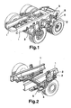
- a heavy vehicle is provided with suspended wheel axles.
- the vehicle chassis frame 1 includes two longitudinal beams extending in the driving direction.
- the wheels are mounted on an axle which is mounted to the frame 1 by a suspension means 2 and dampening means 3.
- an anti-roll bar or stabilizer bar 4 for stabilizing the vehicle and preventing the chassis 1 from rolling, e.g. when driving through corners.
- This stabilizer bar 4 has a portion 4b which extends substantially perpendicular relative to the longitudinal beams 1, i.e. substantially in parallel with the wheel axle.
- the stabilizer bar 4 is mounted to the axle, and at its distal ends the stabilizer bar 4 is pivotably mounted to a stabilizer arm 5 on each side of the vehicle, and these stabilizer arms 5 are anchored to the respective longitudinal beam of the chassis frame 1.
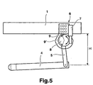
- a stabilizer device is illustrated in a schematic lateral view.
- a stabilizer bar 4 is pivotally mounted to the lower end of a stabilizer arm 5.
- the upper end of the stabilizer arm 5 is pivotally mounted to a stabilizer anchor means 6 which is arranged on a vehicle frame 1.
- the vehicle frame 1 can comprise a first longitudinal beam and a second longitudinal beam.
- a portion 4b of the stabilizer bar 4 extends, preferably substantially in parallel with the wheel axle, from one side to the other side of the frame, i.e. between two stabilizer arms.
- Each stabilizer arm 5 is preferably arranged on the frame via such a stabilizer anchor means 6.
- the stabilizer anchor means 6 can comprise an actuator means 7 such as an electric or hydraulic motor capable of pivoting a pivot member 8, such as disc.
- an actuator means 7 such as an electric or hydraulic motor capable of pivoting a pivot member 8, such as disc.
- the pivot member is illustrated as a disc 8, it should be stressed that other designs are also possible.
- the pivot member could be a rod arranged as a lever arm.
- other possible actuator means are hydraulic or pneumatic cylinders.
- a stabilizer arm attachment point 9 is provided on the pivot member 8 for attachment of the upper end of the stabilizer arm 5.
- the stabilizer arm attachment point 9 is situated off-set relative to the centre of the pivot member 8.
- the stabilizer arm attachment point 9 is displaceable so as to enable the effective length of the stabilizer arm 5 to be adjusted within a predetermined interval.
- the upper position of the stabiliser arm 5 can be moved up or down allowing for an improvement in the lifting strokes as the stabiliser arm 5 is effectively made longer (or shorter) when the disc 8 is pivoted by the motor 7.
- the stabilizer arm attachment point 9 is preferably displaceable mainly in the vertical direction, also a certain displacement in the horizontal direction can be allowed or desired.
- the chassis lifting motion which results in that the effective length of the stabilizer arm is changed, can be accomplished by means of for example air springs arranged on the vehicle. (See Fig. 2 where air springs 2 are arranged between the frame and the wheel axles.)
- the stabilizer arm 5 may be a rod with a fixed length or may be a telescopic arm, such as hydraulic cylinder.
- the motor 7 may preferably include a worm gear for pivoting the pivot member 8 since such gearing may be provided with a high ratio and is self-locking.
- the stabilizer device preferably comprises a fixation or locking means for keeping the position of the stabilizer arm attachment point 9 in the desired position after adjustment of the effective length of the stabilizer arm 5.
- a locking mechanism may include a brake function for fixing the position of the pivot member 8.
- a chassis control system of the vehicle and/or the stabilizer anchor means can be adapted to either prevent or allow displacement of the stabilizer arm attachment point 9 during driving of a vehicle to which vehicle the stabilizing device is mounted.
- the effective lengthening of the stabilizer arm 5 can be provided by mounting the arm 5 onto a pivotally arranged disc 8 of the stabilizer anchor means 6, as shown in fig. 3 and 5 .
- a pivotally arranged disc 8 of the stabilizer anchor means 6, as shown in fig. 3 and 5 may be provided without departing from the invention.
- the main thing is to enable the effective length of the stabilizer arm 5 to be changed or adjusted within a predetermined interval by providing a stabilizer arm attachment point 9 which is displaceable.
- a pivot arm system is used instead of the previously described disc.
- the stabilizer arm attachment point is displaced by a pivot or rotation motion in the illustrated embodiments of the invention, it would be possible to design the stabilizer anchor means so as to make the stabilizer arm attachment point displaceable through a linear movement thereof. The stabilizer arm attachment point is then displaceable preferably in a substantially vertical direction.
- an active stabilizer function is provided to create a force and a level chassis adjustment.
- the torque needed to pivot the disk 8 and thereby "lengthen” the stabilizer arm 5 depends on the size of the vehicle, but it is found that a torque in the interval of 5-100 kNm is needed for most applications.
- the stabilizer device can by the motor 7 actively apply a force on the stabilizer bar 4 to counteract the vehicle roll and keep the chassis level.
- the device can also reduce the stiffness of the suspension when needed, which may be advantageous in relation to off-road trucks, if the axle roll is measured on both sides.
- the vehicle chassis control system of a vehicle can also anticipate a curve and apply a force before the vehicle has started to roll. This would reduce the needed forces from the system and increasing the response time.
- a sensor means (not shown) is preferably included in the stabilizer device for determination of the position of the stabilizer arm attachment point 9, for instance by monitoring the angular position of the disc 8.
- the actuator means 7 may be provided on either side of the stabilizer anchor means 6.
- the pivot member 8 may be angularly displaced between an upper and a lower position for the stabilizer arm attachment point 9.
- the angular displacement is indicated in Fig. 5 by the arrow denoted 9'.
- the height H i.e. the distance between the frame 1 and the stabilizer bar 4 may be altered.
- the stabilizer device preferably comprises a control means (not illustrated) for controlling the stabilizer anchor means 6, i.e. the actuator means 7 of the stabilizer anchor means 6.
- Said control means can cooperate with or be constituted by an already existing chassis control system of the vehicle.
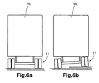
- the stabilizer anchoring means 6 on each side of the vehicle may preferably be operated and controlled independently, which allows for an adjustment of the relative position between the axle 11 and the vehicle chassis 10, as illustrated in Figs. 6a and 6b .
- This means the vehicle chassis 10 may be kept or moved into horizontal after parking so that loading and unloading of goods from the truck can be carried out easily and safely even when the truck is parked on an uneven surface, for instance in cities with a side set of wheels on the side walk.
Landscapes
- Engineering & Computer Science (AREA)
- Mechanical Engineering (AREA)
- Vehicle Body Suspensions (AREA)
- Springs (AREA)
- Cyclones (AREA)
- Soil Working Implements (AREA)
- Excavating Of Shafts Or Tunnels (AREA)
Claims (13)
- Dispositif de stabilisation pour un poids lourd, comprenant une barre stabilisatrice (4) qui peut être fixée sur un essieu de véhicule et montée de manière pivotante par rapport à un châssis de véhicule via des bras stabilisateurs (5), la barre stabilisatrice (4) et le bras stabilisateur (5) respectif étant interconnectés de manière pivotante l'un à l'autre, dans lequel au moins ledit bras stabilisateur (5) est fixé de manière pivotante sur des moyens d'ancrage stabilisateurs (6) au niveau d'un point de fixation de bras stabilisateur (9), lesquels moyens d'ancrage stabilisateurs pouvant être montés sur un châssis de véhicule, le point de fixation de bras stabilisateur (9) pouvant être déplacé de manière à permettre l'ajustement de la longueur effective du bras stabilisateur (5) dans un intervalle-prédéterminé, caractérisé en ce que les moyens d'ancrage stabilisateurs (6) comprennent un élément de pivotement (8) fournissant le point de fixation de bras stabilisateur (9), dans lequel le point de fixation de bras stabilisateur (9) est positionné de manière décentrée par rapport au centre de pivotement de l'élément de pivotement (8), et dans lequel les moyens d'ancrage stabilisateurs (6) comprennent un actionneur (7) pouvant déplacer le point de fixation de bras stabilisateur (9) en faisant pivoter l'élément de pivotement (8).
- Dispositif de stabilisation selon la revendication 1, dans lequel le point de fixation de bras stabilisateur (9) peut être déplacé dans une direction verticale lorsque le dispositif de stabilisation est monté sur un véhicule.
- Dispositif de stabilisation selon la revendication 1 ou 2, dans lequel l'élément de pivotement (8) est un disque.
- Dispositif de stabilisation selon l'une quelconque des revendications précédentes, dans lequel les moyens d'actionnement (7) comprennent un moteur électrique ou hydraulique, ou un cylindre hydraulique ou pneumatique, ou analogue.
- Dispositif de stabilisation selon la revendication 4, dans lequel le dispositif de stabilisation comprend des moyens de commande pour commander les moyens d'ancrage stabilisateurs (6) afin de commander le mouvement de levage du châssis et/ou des caractéristiques de roulement d'un véhicule.
- Dispositif de stabilisation selon la revendication 5, dans lequel lesdits moyens de commande et/ou lesdits moyens d'ancrage stabilisateurs (6) sont adaptés pour permettre un déplacement du point de fixation de bras stabilisateur (9) pendant la conduite d'un véhicule, sur lequel le dispositif de stabilisation est monté.
- Dispositif de stabilisation selon la revendication 5, dans lequel lesdits moyens de commande et/ou lesdits moyens d'ancrage stabilisateurs (6) sont adaptés pour empêcher un déplacement du point de fixation de bras stabilisateur (9) pendant la conduite d'un véhicule, sur lequel le dispositif de stabilisation est monté.
- Dispositif de stabilisation selon l'une quelconque des revendications 5 à 7, dans lequel lesdits moyens de commande coopèrent avec un système de commande de châssis de véhicule, ou sont constitués de celui-ci.
- Dispositif de stabilisation selon l'une quelconque des revendications précédentes, dans lequel le dispositif de stabilisation comprend des moyens de détection afin de déterminer la position du point de fixation de bras stabilisateur (9).
- Dispositif de stabilisation selon l'une quelconque des revendications précédentes, dans lequel ledit au moins un bras stabilisateur a une fonction télescopique.
- Dispositif de stabilisation selon l'une quelconque des revendications précédentes, dans lequel ledit au moins un bras stabilisateur est un cylindre hydraulique.
- Dispositif de stabilisation selon l'une quelconque des revendications précédentes, dans lequel les moyens d'ancrage stabilisateurs (6) comprennent un mécanisme de verrouillage pour fixer la position du point de fixation de bras stabilisateur (9), et ainsi empêcher un déplacement supplémentaire de celui-ci.
- Véhicule comprenant un dispositif de stabilisation selon l'une quelconque des revendications 1 à 12.
Applications Claiming Priority (1)
| Application Number | Priority Date | Filing Date | Title |
|---|---|---|---|
| PCT/SE2006/001238 WO2008054265A1 (fr) | 2006-11-01 | 2006-11-01 | Dispositif de stabilisation pour véhicule lourd |
Publications (3)
| Publication Number | Publication Date |
|---|---|
| EP2081784A1 EP2081784A1 (fr) | 2009-07-29 |
| EP2081784A4 EP2081784A4 (fr) | 2010-01-20 |
| EP2081784B1 true EP2081784B1 (fr) | 2011-04-27 |
Family
ID=39344516
Family Applications (1)
| Application Number | Title | Priority Date | Filing Date |
|---|---|---|---|
| EP06812962A Active EP2081784B1 (fr) | 2006-11-01 | 2006-11-01 | Dispositif de stabilisation pour véhicule lourd |
Country Status (8)
| Country | Link |
|---|---|
| US (1) | US7934733B2 (fr) |
| EP (1) | EP2081784B1 (fr) |
| JP (1) | JP2010508204A (fr) |
| CN (1) | CN101563247A (fr) |
| AT (1) | ATE507096T1 (fr) |
| BR (1) | BRPI0622081A2 (fr) |
| DE (1) | DE602006021643D1 (fr) |
| WO (1) | WO2008054265A1 (fr) |
Families Citing this family (7)
| Publication number | Priority date | Publication date | Assignee | Title |
|---|---|---|---|---|
| DE102011119873A1 (de) | 2011-12-01 | 2012-07-19 | Daimler Ag | Beladungsabhängige Stabilisatorkinematik für eine Radaufhängung eines Kraftfahrzeugs |
| FI124565B (fi) * | 2012-05-31 | 2014-10-15 | Ponsse Oyj | Metsätyöyksikön vakautus |
| US11353084B2 (en) * | 2013-03-15 | 2022-06-07 | Clearmotion Acquisition I Llc | Rotary actuator driven vibration isolation |
| GB2558937A (en) * | 2017-01-23 | 2018-07-25 | Nissan Motor Mfg Uk Ltd | Anti-roll mechanism for road vehicle |
| DE102017208045A1 (de) * | 2017-05-12 | 2018-11-15 | Zf Friedrichshafen Ag | Wankstabilisator mit Sensoren zur Zustandsermittlung |
| DE102018126391B4 (de) | 2018-10-23 | 2021-02-25 | Grammer Aktiengesellschaft | Fahrzeugsitzelement für einen Fahrzeugsitz mit einer Restfederwegverstelleinrichtung |
| EP3922492B1 (fr) * | 2020-06-10 | 2023-09-27 | Volvo Truck Corporation | Agencement de barre antiroulis réglable |
Family Cites Families (20)
| Publication number | Priority date | Publication date | Assignee | Title |
|---|---|---|---|---|
| DE2800549A1 (de) * | 1978-01-07 | 1979-07-12 | Volkswagenwerk Ag | Im niveau geregeltes kraftfahrzeug |
| DE2849015A1 (de) * | 1978-11-11 | 1980-05-22 | Daimler Benz Ag | Stabilisatoranordnung fuer kraftfahrzeuge |
| JPS60169314A (ja) * | 1984-02-14 | 1985-09-02 | Nissan Motor Co Ltd | 車両用スタビライザ |
| US4641856A (en) * | 1985-07-24 | 1987-02-10 | Ford Motor Company | Motor vehicle anti-roll stabilizer system |
| EP0234808B1 (fr) * | 1986-02-17 | 1993-04-21 | Nippondenso Co., Ltd. | Système de commande de stabilisateur |
| JPH0790688B2 (ja) * | 1986-07-18 | 1995-10-04 | カヤバ工業株式会社 | 車両のスタビライザ |
| JPH0717137B2 (ja) * | 1986-10-16 | 1995-03-01 | 日本電装株式会社 | 油圧スタビライザ制御装置 |
| JPH0717142B2 (ja) * | 1987-11-19 | 1995-03-01 | 日本電装株式会社 | スタビライザ制御装置 |
| GB8906229D0 (en) * | 1989-03-17 | 1989-05-04 | Gkn Technology Ltd | Vehicle suspension systems |
| SE464398B (sv) * | 1989-05-12 | 1991-04-22 | Zetterbergs Ind Ab | Anordning vid lastbilar |
| NL8902974A (nl) | 1989-12-01 | 1991-07-01 | Weweler Nv | Voertuig met asophanginrichting met gasvering en besturingssysteem daarvoor. |
| US5186486A (en) * | 1991-07-19 | 1993-02-16 | General Motors Corporation | Active link for a stabilizer bar |
| US5362094A (en) * | 1993-06-09 | 1994-11-08 | General Motors Corporation | Hydraulically controlled stabilizer bar system |
| JP2607266Y2 (ja) * | 1993-06-10 | 2001-05-28 | 日産ディーゼル工業株式会社 | スタビライザ装置 |
| JPH0789324A (ja) * | 1993-09-27 | 1995-04-04 | Nissan Diesel Motor Co Ltd | 車両のスタビライザ装置 |
| DE19510719A1 (de) * | 1995-03-24 | 1996-09-26 | Bayerische Motoren Werke Ag | Vorrichtung zum Befestigen eines Stabilisators eines Fahrzeugs |
| US5954353A (en) * | 1998-02-06 | 1999-09-21 | American Axle & Manufacturing, Inc. | Plug in direct acting stabilizer bar link |
| DE19940420B4 (de) * | 1998-08-26 | 2013-07-11 | Honda Giken Kogyo K.K. | Stabilisatorwirksamkeitssteuergerät |
| US6659475B2 (en) * | 2001-03-06 | 2003-12-09 | Meritor Light Vehicle, Llc | Decouplable link for a stabilizer bar |
| KR100514845B1 (ko) * | 2002-12-05 | 2005-09-14 | 현대자동차주식회사 | 스테빌라이저 바아의 롤 강성 조정 장치 |
-
2006
- 2006-11-01 BR BRPI0622081-9A patent/BRPI0622081A2/pt not_active IP Right Cessation
- 2006-11-01 JP JP2009535231A patent/JP2010508204A/ja active Pending
- 2006-11-01 US US12/513,172 patent/US7934733B2/en not_active Expired - Fee Related
- 2006-11-01 WO PCT/SE2006/001238 patent/WO2008054265A1/fr active Application Filing
- 2006-11-01 EP EP06812962A patent/EP2081784B1/fr active Active
- 2006-11-01 AT AT06812962T patent/ATE507096T1/de not_active IP Right Cessation
- 2006-11-01 CN CNA2006800562888A patent/CN101563247A/zh active Pending
- 2006-11-01 DE DE602006021643T patent/DE602006021643D1/de active Active
Also Published As
| Publication number | Publication date |
|---|---|
| EP2081784A4 (fr) | 2010-01-20 |
| US7934733B2 (en) | 2011-05-03 |
| JP2010508204A (ja) | 2010-03-18 |
| EP2081784A1 (fr) | 2009-07-29 |
| DE602006021643D1 (de) | 2011-06-09 |
| WO2008054265A1 (fr) | 2008-05-08 |
| US20100117323A1 (en) | 2010-05-13 |
| BRPI0622081A2 (pt) | 2014-05-20 |
| CN101563247A (zh) | 2009-10-21 |
| ATE507096T1 (de) | 2011-05-15 |
Similar Documents
| Publication | Publication Date | Title |
|---|---|---|
| EP2081784B1 (fr) | Dispositif de stabilisation pour véhicule lourd | |
| KR101409029B1 (ko) | 차량 바디 및 섀시를 구비한 차량 | |
| EP2354078B1 (fr) | Camion industriel | |
| US7770904B2 (en) | Stability system for an industrial vehicle | |
| US5505482A (en) | Road-railer suspension system having a spring lift and a stabilizer bar | |
| US5403031A (en) | Parallelogram lift axle suspension system with a control for axle caster adjustment | |
| EP2085299A2 (fr) | Système de stabilisation de véhicule articulé | |
| WO2009120334A2 (fr) | Système de suspension à stabilité renforcée | |
| WO2006019298A1 (fr) | Systeme anti-roulis/tangage pour vehicule et vehicule equipe de ce systeme | |
| US8220809B2 (en) | Independent parallelogram suspension system | |
| JP3691262B2 (ja) | 懸架装置 | |
| JPH0512164B2 (fr) | ||
| US9995012B2 (en) | Wheeled snowplough system | |
| KR20070122375A (ko) | 차량 섀시를 안정화시키는 보조 판 스프링을 사용하는 방법및 장치 | |
| US5566971A (en) | Vehicle air suspension system | |
| EP2886377B1 (fr) | Dispositif de nivellement de cabine et camion ou tracteur équipé du dispositif de nivellement de cabine | |
| EP3459814B1 (fr) | Dispositif de roue de support de stabilisation et chariot de manutention comprenant un tel dispositif de roue de support | |
| US20090001677A1 (en) | Dynamically Adjustable Panhard Bar | |
| EP3377341B1 (fr) | Suspension d'essieu de roue avec dispositif de levage d'essieu | |
| EP1527912B1 (fr) | Suspension à essieu rigide pour un véhicule, notamment véhicule utilitaire | |
| US6634655B2 (en) | Dock height hold device | |
| US20220410988A1 (en) | Automated compensator for fifth-wheel couplings | |
| JP2772745B2 (ja) | 磁気浮上車両用脚装置 | |
| CN113771575A (zh) | 可调防倾杆装置 | |
| JP3884250B2 (ja) | 車高の変位抑制装置 |
Legal Events
| Date | Code | Title | Description |
|---|---|---|---|
| PUAI | Public reference made under article 153(3) epc to a published international application that has entered the european phase |
Free format text: ORIGINAL CODE: 0009012 |
|
| 17P | Request for examination filed |
Effective date: 20090602 |
|
| AK | Designated contracting states |
Kind code of ref document: A1 Designated state(s): AT BE BG CH CY CZ DE DK EE ES FI FR GB GR HU IE IS IT LI LT LU LV MC NL PL PT RO SE SI SK TR |
|
| A4 | Supplementary search report drawn up and despatched |
Effective date: 20091221 |
|
| DAX | Request for extension of the european patent (deleted) | ||
| 17Q | First examination report despatched |
Effective date: 20100416 |
|
| GRAP | Despatch of communication of intention to grant a patent |
Free format text: ORIGINAL CODE: EPIDOSNIGR1 |
|
| RIC1 | Information provided on ipc code assigned before grant |
Ipc: B60G 21/055 20060101AFI20101026BHEP |
|
| GRAS | Grant fee paid |
Free format text: ORIGINAL CODE: EPIDOSNIGR3 |
|
| GRAA | (expected) grant |
Free format text: ORIGINAL CODE: 0009210 |
|
| AK | Designated contracting states |
Kind code of ref document: B1 Designated state(s): AT BE BG CH CY CZ DE DK EE ES FI FR GB GR HU IE IS IT LI LT LU LV MC NL PL PT RO SE SI SK TR |
|
| REG | Reference to a national code |
Ref country code: GB Ref legal event code: FG4D |
|
| REG | Reference to a national code |
Ref country code: CH Ref legal event code: EP |
|
| REG | Reference to a national code |
Ref country code: IE Ref legal event code: FG4D |
|
| REF | Corresponds to: |
Ref document number: 602006021643 Country of ref document: DE Date of ref document: 20110609 Kind code of ref document: P |
|
| REG | Reference to a national code |
Ref country code: DE Ref legal event code: R096 Ref document number: 602006021643 Country of ref document: DE Effective date: 20110609 |
|
| REG | Reference to a national code |
Ref country code: NL Ref legal event code: VDEP Effective date: 20110427 |
|
| LTIE | Lt: invalidation of european patent or patent extension |
Effective date: 20110427 |
|
| PG25 | Lapsed in a contracting state [announced via postgrant information from national office to epo] |
Ref country code: LT Free format text: LAPSE BECAUSE OF FAILURE TO SUBMIT A TRANSLATION OF THE DESCRIPTION OR TO PAY THE FEE WITHIN THE PRESCRIBED TIME-LIMIT Effective date: 20110427 Ref country code: PT Free format text: LAPSE BECAUSE OF FAILURE TO SUBMIT A TRANSLATION OF THE DESCRIPTION OR TO PAY THE FEE WITHIN THE PRESCRIBED TIME-LIMIT Effective date: 20110829 Ref country code: SE Free format text: LAPSE BECAUSE OF FAILURE TO SUBMIT A TRANSLATION OF THE DESCRIPTION OR TO PAY THE FEE WITHIN THE PRESCRIBED TIME-LIMIT Effective date: 20110427 |
|
| PG25 | Lapsed in a contracting state [announced via postgrant information from national office to epo] |
Ref country code: AT Free format text: LAPSE BECAUSE OF FAILURE TO SUBMIT A TRANSLATION OF THE DESCRIPTION OR TO PAY THE FEE WITHIN THE PRESCRIBED TIME-LIMIT Effective date: 20110427 Ref country code: IS Free format text: LAPSE BECAUSE OF FAILURE TO SUBMIT A TRANSLATION OF THE DESCRIPTION OR TO PAY THE FEE WITHIN THE PRESCRIBED TIME-LIMIT Effective date: 20110827 Ref country code: CY Free format text: LAPSE BECAUSE OF FAILURE TO SUBMIT A TRANSLATION OF THE DESCRIPTION OR TO PAY THE FEE WITHIN THE PRESCRIBED TIME-LIMIT Effective date: 20110427 Ref country code: GR Free format text: LAPSE BECAUSE OF FAILURE TO SUBMIT A TRANSLATION OF THE DESCRIPTION OR TO PAY THE FEE WITHIN THE PRESCRIBED TIME-LIMIT Effective date: 20110728 Ref country code: LV Free format text: LAPSE BECAUSE OF FAILURE TO SUBMIT A TRANSLATION OF THE DESCRIPTION OR TO PAY THE FEE WITHIN THE PRESCRIBED TIME-LIMIT Effective date: 20110427 Ref country code: FI Free format text: LAPSE BECAUSE OF FAILURE TO SUBMIT A TRANSLATION OF THE DESCRIPTION OR TO PAY THE FEE WITHIN THE PRESCRIBED TIME-LIMIT Effective date: 20110427 Ref country code: ES Free format text: LAPSE BECAUSE OF FAILURE TO SUBMIT A TRANSLATION OF THE DESCRIPTION OR TO PAY THE FEE WITHIN THE PRESCRIBED TIME-LIMIT Effective date: 20110807 Ref country code: BE Free format text: LAPSE BECAUSE OF FAILURE TO SUBMIT A TRANSLATION OF THE DESCRIPTION OR TO PAY THE FEE WITHIN THE PRESCRIBED TIME-LIMIT Effective date: 20110427 Ref country code: SI Free format text: LAPSE BECAUSE OF FAILURE TO SUBMIT A TRANSLATION OF THE DESCRIPTION OR TO PAY THE FEE WITHIN THE PRESCRIBED TIME-LIMIT Effective date: 20110427 |
|
| PG25 | Lapsed in a contracting state [announced via postgrant information from national office to epo] |
Ref country code: NL Free format text: LAPSE BECAUSE OF FAILURE TO SUBMIT A TRANSLATION OF THE DESCRIPTION OR TO PAY THE FEE WITHIN THE PRESCRIBED TIME-LIMIT Effective date: 20110427 |
|
| PG25 | Lapsed in a contracting state [announced via postgrant information from national office to epo] |
Ref country code: EE Free format text: LAPSE BECAUSE OF FAILURE TO SUBMIT A TRANSLATION OF THE DESCRIPTION OR TO PAY THE FEE WITHIN THE PRESCRIBED TIME-LIMIT Effective date: 20110427 Ref country code: CZ Free format text: LAPSE BECAUSE OF FAILURE TO SUBMIT A TRANSLATION OF THE DESCRIPTION OR TO PAY THE FEE WITHIN THE PRESCRIBED TIME-LIMIT Effective date: 20110427 |
|
| PG25 | Lapsed in a contracting state [announced via postgrant information from national office to epo] |
Ref country code: DK Free format text: LAPSE BECAUSE OF FAILURE TO SUBMIT A TRANSLATION OF THE DESCRIPTION OR TO PAY THE FEE WITHIN THE PRESCRIBED TIME-LIMIT Effective date: 20110427 Ref country code: PL Free format text: LAPSE BECAUSE OF FAILURE TO SUBMIT A TRANSLATION OF THE DESCRIPTION OR TO PAY THE FEE WITHIN THE PRESCRIBED TIME-LIMIT Effective date: 20110427 Ref country code: RO Free format text: LAPSE BECAUSE OF FAILURE TO SUBMIT A TRANSLATION OF THE DESCRIPTION OR TO PAY THE FEE WITHIN THE PRESCRIBED TIME-LIMIT Effective date: 20110427 Ref country code: SK Free format text: LAPSE BECAUSE OF FAILURE TO SUBMIT A TRANSLATION OF THE DESCRIPTION OR TO PAY THE FEE WITHIN THE PRESCRIBED TIME-LIMIT Effective date: 20110427 |
|
| PLBE | No opposition filed within time limit |
Free format text: ORIGINAL CODE: 0009261 |
|
| STAA | Information on the status of an ep patent application or granted ep patent |
Free format text: STATUS: NO OPPOSITION FILED WITHIN TIME LIMIT |
|
| 26N | No opposition filed |
Effective date: 20120130 |
|
| REG | Reference to a national code |
Ref country code: DE Ref legal event code: R097 Ref document number: 602006021643 Country of ref document: DE Effective date: 20120130 |
|
| PG25 | Lapsed in a contracting state [announced via postgrant information from national office to epo] |
Ref country code: IT Free format text: LAPSE BECAUSE OF FAILURE TO SUBMIT A TRANSLATION OF THE DESCRIPTION OR TO PAY THE FEE WITHIN THE PRESCRIBED TIME-LIMIT Effective date: 20110427 |
|
| PG25 | Lapsed in a contracting state [announced via postgrant information from national office to epo] |
Ref country code: MC Free format text: LAPSE BECAUSE OF NON-PAYMENT OF DUE FEES Effective date: 20111130 |
|
| REG | Reference to a national code |
Ref country code: CH Ref legal event code: PL |
|
| PG25 | Lapsed in a contracting state [announced via postgrant information from national office to epo] |
Ref country code: CH Free format text: LAPSE BECAUSE OF NON-PAYMENT OF DUE FEES Effective date: 20111130 Ref country code: LI Free format text: LAPSE BECAUSE OF NON-PAYMENT OF DUE FEES Effective date: 20111130 |
|
| REG | Reference to a national code |
Ref country code: IE Ref legal event code: MM4A |
|
| PG25 | Lapsed in a contracting state [announced via postgrant information from national office to epo] |
Ref country code: IE Free format text: LAPSE BECAUSE OF NON-PAYMENT OF DUE FEES Effective date: 20111101 |
|
| PG25 | Lapsed in a contracting state [announced via postgrant information from national office to epo] |
Ref country code: LU Free format text: LAPSE BECAUSE OF NON-PAYMENT OF DUE FEES Effective date: 20111101 |
|
| PG25 | Lapsed in a contracting state [announced via postgrant information from national office to epo] |
Ref country code: BG Free format text: LAPSE BECAUSE OF FAILURE TO SUBMIT A TRANSLATION OF THE DESCRIPTION OR TO PAY THE FEE WITHIN THE PRESCRIBED TIME-LIMIT Effective date: 20110727 |
|
| PG25 | Lapsed in a contracting state [announced via postgrant information from national office to epo] |
Ref country code: TR Free format text: LAPSE BECAUSE OF FAILURE TO SUBMIT A TRANSLATION OF THE DESCRIPTION OR TO PAY THE FEE WITHIN THE PRESCRIBED TIME-LIMIT Effective date: 20110427 |
|
| PG25 | Lapsed in a contracting state [announced via postgrant information from national office to epo] |
Ref country code: HU Free format text: LAPSE BECAUSE OF FAILURE TO SUBMIT A TRANSLATION OF THE DESCRIPTION OR TO PAY THE FEE WITHIN THE PRESCRIBED TIME-LIMIT Effective date: 20110427 |
|
| REG | Reference to a national code |
Ref country code: FR Ref legal event code: PLFP Year of fee payment: 10 |
|
| REG | Reference to a national code |
Ref country code: FR Ref legal event code: PLFP Year of fee payment: 11 |
|
| PGFP | Annual fee paid to national office [announced via postgrant information from national office to epo] |
Ref country code: FR Payment date: 20161124 Year of fee payment: 11 Ref country code: GB Payment date: 20161107 Year of fee payment: 11 |
|
| GBPC | Gb: european patent ceased through non-payment of renewal fee |
Effective date: 20171101 |
|
| REG | Reference to a national code |
Ref country code: FR Ref legal event code: ST Effective date: 20180731 |
|
| PG25 | Lapsed in a contracting state [announced via postgrant information from national office to epo] |
Ref country code: FR Free format text: LAPSE BECAUSE OF NON-PAYMENT OF DUE FEES Effective date: 20171130 |
|
| PG25 | Lapsed in a contracting state [announced via postgrant information from national office to epo] |
Ref country code: GB Free format text: LAPSE BECAUSE OF NON-PAYMENT OF DUE FEES Effective date: 20171101 |
|
| PGFP | Annual fee paid to national office [announced via postgrant information from national office to epo] |
Ref country code: DE Payment date: 20220527 Year of fee payment: 17 |