EP2081258A1 - Réflecteur secondaire d'une antenne à double réflecteur - Google Patents
Réflecteur secondaire d'une antenne à double réflecteur Download PDFInfo
- Publication number
- EP2081258A1 EP2081258A1 EP09150680A EP09150680A EP2081258A1 EP 2081258 A1 EP2081258 A1 EP 2081258A1 EP 09150680 A EP09150680 A EP 09150680A EP 09150680 A EP09150680 A EP 09150680A EP 2081258 A1 EP2081258 A1 EP 2081258A1
- Authority
- EP
- European Patent Office
- Prior art keywords
- reflector
- antenna
- secondary reflector
- primary
- diameter
- Prior art date
- Legal status (The legal status is an assumption and is not a legal conclusion. Google has not performed a legal analysis and makes no representation as to the accuracy of the status listed.)
- Granted
Links
- 230000009977 dual effect Effects 0.000 claims description 12
- 230000008878 coupling Effects 0.000 claims description 4
- 238000010168 coupling process Methods 0.000 claims description 4
- 238000005859 coupling reaction Methods 0.000 claims description 4
- 230000005855 radiation Effects 0.000 description 27
- 238000005286 illumination Methods 0.000 description 11
- 230000005540 biological transmission Effects 0.000 description 6
- 229910052782 aluminium Inorganic materials 0.000 description 4
- XAGFODPZIPBFFR-UHFFFAOYSA-N aluminium Chemical compound [Al] XAGFODPZIPBFFR-UHFFFAOYSA-N 0.000 description 4
- 238000004519 manufacturing process Methods 0.000 description 3
- 229910052751 metal Inorganic materials 0.000 description 3
- 239000002184 metal Substances 0.000 description 3
- 230000009467 reduction Effects 0.000 description 3
- 238000002310 reflectometry Methods 0.000 description 3
- 208000031968 Cadaver Diseases 0.000 description 2
- 230000008901 benefit Effects 0.000 description 2
- 230000000295 complement effect Effects 0.000 description 2
- 239000000463 material Substances 0.000 description 2
- 238000005457 optimization Methods 0.000 description 2
- UGFAIRIUMAVXCW-UHFFFAOYSA-N Carbon monoxide Chemical class [O+]#[C-] UGFAIRIUMAVXCW-UHFFFAOYSA-N 0.000 description 1
- 230000002745 absorbent Effects 0.000 description 1
- 239000002250 absorbent Substances 0.000 description 1
- 229910002090 carbon oxide Inorganic materials 0.000 description 1
- 230000008859 change Effects 0.000 description 1
- 239000011248 coating agent Substances 0.000 description 1
- 238000000576 coating method Methods 0.000 description 1
- 230000005574 cross-species transmission Effects 0.000 description 1
- 239000003989 dielectric material Substances 0.000 description 1
- 230000000694 effects Effects 0.000 description 1
- 230000005684 electric field Effects 0.000 description 1
- 239000006260 foam Substances 0.000 description 1
- 230000006872 improvement Effects 0.000 description 1
- 238000000034 method Methods 0.000 description 1
- 230000000737 periodic effect Effects 0.000 description 1
- 230000002093 peripheral effect Effects 0.000 description 1
- 230000010287 polarization Effects 0.000 description 1
- 229910052709 silver Inorganic materials 0.000 description 1
- 239000004332 silver Substances 0.000 description 1
- 238000003466 welding Methods 0.000 description 1
Images




Classifications
-
- H—ELECTRICITY
- H01—ELECTRIC ELEMENTS
- H01Q—ANTENNAS, i.e. RADIO AERIALS
- H01Q19/00—Combinations of primary active antenna elements and units with secondary devices, e.g. with quasi-optical devices, for giving the antenna a desired directional characteristic
- H01Q19/10—Combinations of primary active antenna elements and units with secondary devices, e.g. with quasi-optical devices, for giving the antenna a desired directional characteristic using reflecting surfaces
- H01Q19/18—Combinations of primary active antenna elements and units with secondary devices, e.g. with quasi-optical devices, for giving the antenna a desired directional characteristic using reflecting surfaces having two or more spaced reflecting surfaces
- H01Q19/19—Combinations of primary active antenna elements and units with secondary devices, e.g. with quasi-optical devices, for giving the antenna a desired directional characteristic using reflecting surfaces having two or more spaced reflecting surfaces comprising one main concave reflecting surface associated with an auxiliary reflecting surface
-
- H—ELECTRICITY
- H01—ELECTRIC ELEMENTS
- H01Q—ANTENNAS, i.e. RADIO AERIALS
- H01Q19/00—Combinations of primary active antenna elements and units with secondary devices, e.g. with quasi-optical devices, for giving the antenna a desired directional characteristic
- H01Q19/10—Combinations of primary active antenna elements and units with secondary devices, e.g. with quasi-optical devices, for giving the antenna a desired directional characteristic using reflecting surfaces
- H01Q19/18—Combinations of primary active antenna elements and units with secondary devices, e.g. with quasi-optical devices, for giving the antenna a desired directional characteristic using reflecting surfaces having two or more spaced reflecting surfaces
- H01Q19/19—Combinations of primary active antenna elements and units with secondary devices, e.g. with quasi-optical devices, for giving the antenna a desired directional characteristic using reflecting surfaces having two or more spaced reflecting surfaces comprising one main concave reflecting surface associated with an auxiliary reflecting surface
- H01Q19/193—Combinations of primary active antenna elements and units with secondary devices, e.g. with quasi-optical devices, for giving the antenna a desired directional characteristic using reflecting surfaces having two or more spaced reflecting surfaces comprising one main concave reflecting surface associated with an auxiliary reflecting surface with feed supported subreflector
-
- H—ELECTRICITY
- H01—ELECTRIC ELEMENTS
- H01Q—ANTENNAS, i.e. RADIO AERIALS
- H01Q15/00—Devices for reflection, refraction, diffraction or polarisation of waves radiated from an antenna, e.g. quasi-optical devices
- H01Q15/14—Reflecting surfaces; Equivalent structures
- H01Q15/141—Apparatus or processes specially adapted for manufacturing reflecting surfaces
- H01Q15/142—Apparatus or processes specially adapted for manufacturing reflecting surfaces using insulating material for supporting the reflecting surface
-
- H—ELECTRICITY
- H01—ELECTRIC ELEMENTS
- H01Q—ANTENNAS, i.e. RADIO AERIALS
- H01Q19/00—Combinations of primary active antenna elements and units with secondary devices, e.g. with quasi-optical devices, for giving the antenna a desired directional characteristic
- H01Q19/10—Combinations of primary active antenna elements and units with secondary devices, e.g. with quasi-optical devices, for giving the antenna a desired directional characteristic using reflecting surfaces
- H01Q19/12—Combinations of primary active antenna elements and units with secondary devices, e.g. with quasi-optical devices, for giving the antenna a desired directional characteristic using reflecting surfaces wherein the surfaces are concave
- H01Q19/13—Combinations of primary active antenna elements and units with secondary devices, e.g. with quasi-optical devices, for giving the antenna a desired directional characteristic using reflecting surfaces wherein the surfaces are concave the primary radiating source being a single radiating element, e.g. a dipole, a slot, a waveguide termination
- H01Q19/134—Rear-feeds; Splash plate feeds
Definitions
- the present invention relates to Radio Frequency (RF) antennas with dual reflectors.
- RF Radio Frequency
- These antennas generally comprise a large-diameter concave primary reflector having a surface of revolution, and a convex smaller-diameter secondary reflector ("sub-reflector") located near the focus of the primary reflector.
- sub-reflector convex smaller-diameter secondary reflector located near the focus of the primary reflector.
- These antennas operate indifferently in transmitter mode or in receiver mode, corresponding to two opposite directions of RF wave propagation.
- the description is given either in transmission mode or in reception mode of the antenna, according to which allows to better illustrate the described phenomena. It should be noted that all the reasonings apply to the antennas as well in reception as in emission.
- the first antennas had only one reflector, most often parabolic.
- the end of the radiofrequency waveguide is at the focus of the reflector.
- the waveguide is inserted into an orifice on the axis of the reflector, and its end is bent 180 ° to face the reflector.
- the maximum half-angle of radiation at the folded end of the waveguide to illuminate the reflector is small, of the order of 70 °.
- the distance between the reflector and the end of the waveguide must be large enough to illuminate the entire surface of the reflector.
- the F / D ratio is of the order of 0.36. In this report, F is the focal length of the reflector (distance between the top of the reflector and its focus) and D is the diameter of the reflector.
- the value of the diameter D is determined by the central working frequency of the antenna.
- annular reliefs on the outer surface of the dielectric body reduces the multiple reflections of RF waves that occur between the waveguide and the primary reflector via the metallized inner surface of the secondary reflector.
- these reliefs have a lesser effect on two other important characteristics of the double reflector: the antenna gain, expressed in dBi or isotropic decibel, and the spillover losses, expressed in dB.
- the overflow losses correspond to the energy reflected by the secondary reflector towards the primary reflector, and whose path ends beyond the outer diameter of the primary reflector. These losses lead to pollution of the environment by RF waves. These overflow losses should be limited to levels defined by standards.
- a conventional solution is to attach to the periphery of the primary reflector a skirt which has the shape of a cylinder, of diameter close to that of the primary reflector and of suitable height, lined internally with a layer absorbing RF radiation.
- this known solution has the inconvenient today inconvenient cost of the material of the skirt, as well as the cost of assembling this skirt on the primary reflector.
- the present invention aims to provide a dual reflector antenna whose losses overflow are significantly reduced.
- dual reflector antennas are used, in particular those referred to as Cassegrain type.
- the double reflectors comprise a concave primary reflector, frequently parabolic, and a convex secondary reflector having a much smaller diameter and placed in the vicinity of the focus on the same axis of revolution as the primary reflector.
- the primary reflector is pierced at its top and the waveguide is inserted on the axis of the primary reflector. The end of the waveguide is no longer folded, but faces the secondary reflector.
- the RF waves transmitted by the waveguide are reflected by the secondary reflector to the primary reflector.
- secondary reflectors having a half-angle of illumination of the primary reflector much greater than 70 °.
- an illumination half-angle of 105 ° can be used.
- the secondary reflector can thus be axially very close to the primary reflector.
- the secondary reflector may be located within the volume defined by the primary reflector which reduces the size of the antenna.
- the F / D ratio used is often less than or equal to 0.25.
- These antenna are said to deep reflector ("deep reflector" in English).
- An F / D ratio of the order of 0.25 corresponds, for the same value of the central working frequency D. at a shorter focal length than in the case where the F / D ratio is close to 0.36.
- the size of a double reflector antenna can therefore be smaller than that of a single reflector antenna by eliminating the absorbing screen which is no longer essential.
- the dual reflector antennas are well suited to the production of compact antennas, for example by using double reflectors whose F / D ratio is close to 0.2, it may be preferable to use F / D values other than to optimize also other characteristics that congestion, such as the radiation pattern of the antenna for example.
- the secondary reflector In a dual reflector antenna, the secondary reflector must be maintained in the vicinity of the focus of the primary reflector.
- One of the possible ways is to fix the secondary reflector at the end of the waveguide.
- the secondary reflector usually comprises a dielectric body (frequently plastic) of generally conical shape and transparent to RF waves.
- the substantially conical outer surface of the secondary reflector faces the primary reflector.
- the convex inner surface of the secondary reflector is coated with a treatment
- the invention consists in proposing a secondary reflector whose outer surface has a profile according to a particular curve.
- the secondary reflector is a volume of axial symmetry having a surface whose generator is a curve described by a polynomial equation of degree 6. Numerical optimizations make it possible to adapt the coefficients of this polynomial equation of degree 6 according to the type of double reflector used. and the possible presence of a skirt.
- the outer surface of the secondary reflector further comprises a single ring-shaped relief surrounding the dielectric body.
- the section of this relief may be a portion of a disk or a parallelogram (square or rectangle for example).
- the relief has a rectangular section.
- the relief projects in a direction perpendicular to the axis of revolution of the secondary reflector.
- This unique raised ring is placed on the outer surface of the secondary reflector to reduce the multiple reflections of the RF wave. At the same time, a reduction in overflow losses and multiple reflections of the RF waves is achieved simultaneously.
- the relief is disposed on the half of the outer surface closest to the second end.
- the present invention makes it possible to dispense with the skirt, or at least to reduce the height of the skirt of the primary reflector, which provides a cost and space advantage.
- the improvement afforded by the invention makes it possible to use a skirt of low height which can be made in one piece with the primary reflector, that is to say that a single mechanical part having a reflector is produced in the central part and a skirt in the peripheral part.
- This entails an additional cost reduction compared to the conventional solution of a skirt attached to a primary reflector by any known method such as welding, screwing, etc. This saves the cost of assembly.
- the invention can be used in applications such as, for example, the production of terrestrial antennas for receiving a radiofrequency signal emitted by a satellite or the link between two terrestrial antennas, and more generally in any application concerning radiofrequency links.
- point-to-point in the frequency band from 7 GHz to 40 GHz.
- the typical central frequencies of operation of these systems are 7.1 GHz, 8.5 GHz, 10 GHz, etc.
- the bandwidth around each frequency is in general of the order of 5% to 20%.
- Each central frequency corresponds to a suitable secondary reflector diameter: the higher the frequency, the shorter the wavelength, and the smaller the diameter of the secondary reflector.
- the amplitude in dBi of the radiation V in the vertical plane and the radiation H in the horizontal plane respectively of the secondary reflector are given on the ordinate, and on the abscissa the half-angle of illumination ⁇ in degrees.
- the radiation T of the primary reflector is expressed in dB on the ordinate and on the abscissa the half-angle ⁇ expressed in degrees.
- the radiation T of the primary reflector is normalized to 0 dB for a half-angle ⁇ equal to zero degrees.
- an RF antenna is shown according to a first embodiment of the invention.
- This antenna comprises an assembly consisting of a concave primary reflector 1 and a secondary reflector 2, as well as a waveguide 3 also serving as mechanical support for the secondary reflector 2.
- the assembly has a symmetry of revolution around axis 4.
- the primary reflector 1 may be of metal with a reflective surface, for example aluminum.
- the waveguide 3 may be, for example, a metallic hollow tube, also of aluminum, of circular section having an outside diameter of 26 mm or 3 mm. , 6 mm for transmission / reception frequencies respectively of 7 GHz and 60 GHz.
- the waveguide could have a different section, rectangular or square, for example.
- the focal point 5 (also called the phase center) on the axis of revolution 4 is represented, and the focal length F 6 which separates the focus from the top of the primary reflector 1.
- the primary reflector 1 is, for example, a paraboloid of revolution. around the axis 4 with a depth P 7 and a diameter D 8.
- the focal length F is for example 246 mm and the diameter D is 1230 mm (4 feet).
- the angle of limit illumination 2 ⁇ p of the primary reflector is 210 °.
- the figure 2 represents the secondary reflector 10 of an antenna according to the first embodiment of the invention.
- the dielectric body 11 of the secondary reflector may be of a dielectric material such as plastic.
- the inner surface 12 of the secondary reflector 10 may be a surface of revolution described by a polynomial equation around an axis of revolution 13.
- the inner surface 12 may be covered with a reflective metal, such as silver.
- the outer surface 14 of the secondary reflector 10 is the surface placed opposite the primary reflector.
- the outer surface 14 is a surface of revolution about the axis of revolution 13.
- the Calculations make it possible to show that the choice of such a curved profile for the external surface 14 makes it possible to reduce the overflow losses of the double reflector.
- the shape of the inner surface of the secondary reflector influences the intensity and phase of the electromagnetic wave from the waveguide and received by the primary reflector.
- the figure 3 represents the secondary reflector 20 of an antenna according to a second embodiment of the invention.
- a relief 21 forming a ring is formed on the outer surface 22 of the reflector 20.
- the outer surface 22 of the reflector 20 consists of three successive portions 22a , 21, 22b.
- the portions 22a and 22b each have a profile described by a portion of the sixth degree curve.
- the parts 22a and 22b and the relief 21 have a symmetry of revolution about the axis of revolution 23.
- the overflow losses for the transmission mode of an RF antenna according to the first embodiment of the invention are explained on the figure 4 . These losses correspond to values of the illumination angle 20 of the primary reflector by the secondary reflector for which the RF waves from the waveguide 3 are reflected by the secondary reflector 2 in a direction which is outside the perimeter of the reflector. primary reflector 1.
- This figure shows the illumination half-angle ⁇ (theta) 30 and the half-angle ⁇ (beta) 31, which is the half-angle complementary to the half-angle ⁇ .
- the two half-angles ⁇ and ⁇ are measured with respect to the axis of revolution 4 of the secondary reflector 2, and their vertex is the focus 5 of the primary reflector 1.
- the overflow losses are therefore due to all the rays 33 reflected by the secondary reflector 2 within the angular range 34.
- the angular range 34 is defined by two radii 35, from the focus 5 and symmetrical with respect to the axis of revolution 4, which are tangent to the edges of the primary reflector 1.
- the figure 5 represents an axial sectional view of an RF antenna according to a variant of the first embodiment of the invention.
- the primary reflector 50 is provided with a skirt 51 in order to limit the losses by overflow.
- the skirt 51 is a screen covered with a material 52 absorbing RF waves.
- the skirt 51 is made of aluminum and the absorbent layer 52 consists of a foam loaded with carbon oxides.
- the skirt 51 is of less height than the skirts used in the prior art, because the overflow losses are significantly reduced by the use of a secondary reflector 53 provided with an external surface 54 having a profile according to a curve described by a polynomial equation of the sixth degree.
- the parameters of the sixth-degree equation describing the profile of the external surface 54 can be optimized. This optimization makes it possible to reduce the height of the skirt 51 to allow the production of a single piece of the primary reflector 50 and the skirt 51, as shown in figure 5 .
- the skirt 51 thus constitutes an extension of the primary reflector 50. This can be achieved for example by stamping a single aluminum plate so as to define successively or simultaneously the shape, preferably paraboloid of revolution, of the primary reflector 50 and the shape, preferably cylindrical, of the skirt 51.
- the figure 6 represents an exemplary profile 60 of the outer surface of the secondary reflector according to a particular embodiment of the invention, which was obtained by digitizing the level of overflow losses.
- the reference (X, Y) originates from a point of the axis of revolution 13 located at the second end of the secondary reflector 10.
- the axis X is aligned with the axis of revolution 13 and the axis Y has a direction perpendicular to the axis of revolution 13. The distances are expressed in centimeters.
- the numerical values given here for the parameters a, b, c, d, e, f, g of the sixth degree equation depend on the numerical values chosen for the focal length F, the depth P and the diameter D of the primary reflector. as well as the level of overflow losses that we allow our. If we change these numerical values, we can find another set of values for the parameters a, b, c, d, e, t, g to minimize the overflow losses. Thus the parameters a, b, c, d, e, f, g of the sixth degree equation can take different values.
- the radiation pattern is represented by the amplitude of the radiation V expressed as a function of the illumination half-angle ⁇ . This radiation pattern is relative to the antenna in transmission mode.
- the best antenna design is that which makes it possible to obtain a radiation, or emitted electric field, as small as possible for the illumination half-angle values ⁇ greater than the limit value ⁇ p represented here by the vertical line 73 .
- the vertical line 73 represents the p ⁇ value of the half angle ⁇ which is tangential to the outer edge of the primary reflector as shown in figure 4 .
- the rays are reflected in the angular range 34 and participate in overflow losses.
- the curve 71 associated with the first embodiment according to the invention, shows a lower radiation for values of the angle ⁇ greater than the value ⁇ p that the radiation given by the curve 70 associated with a profile of the prior art.
- the curve 72 associated with a second embodiment according to the invention further improves the result obtained with the curve 71.
- the vertical line 83 represents the value ⁇ p of the half-angle ⁇ which tangents the outer edge of the primary reflector as shown in FIG. figure 4 .
- the best antenna design is that which makes it possible to obtain the lowest radiation for the half-angles 0, greater than the value ⁇ p , situated to the right of the vertical line 83.
- curve 81 associated with the first embodiment according to the invention shows radiation values lower than the values given by the curve 80 associated with a profile of the prior art.
- Curve 82 associated with a second embodiment according to the invention further improves the result obtained with curve 81.
- the figure 9 shows the radiation pattern of the primary reflector as a function of the half-angle ⁇ of a double-reflector antenna according to the prior art.
- the power levels reflected in the vertical and horizontal planes of the antenna as a function of the half-angle ⁇ are represented on the ordinate.
- the curve 90 corresponds to the power reflected in the vertical plane
- the curve 91 corresponds to the power reflected in the horizontal plane.
- a broken line 92 indicates for each value of the half-angle ⁇ the reflectivity limits allowed by ETSI standard R1C3 Co.
- the difference 93 between the value of the radiation of the primary reflector and the limit value imposed by the standard is here of the order of 5 dB.
- the figure 10 relates to a dual reflector antenna using a secondary reflector according to a first embodiment of the invention.
- the outer surface of the antenna has a profile described by a polynomial equation of the sixth degree.
- the reflected power levels in the vertical and horizontal planes of the antenna are represented as a function of the half-angle ⁇ .
- the curve 100 corresponds to the power reflected in the vertical plane and the curve 101 corresponds to the power reflected in the horizontal plane.
- a broken line 102 indicates, for each value of the half-angle ⁇ the reflectivity limits authorized by the ETSI R1C3 Co. standard.
- the difference 103 is here of the order of 7 dB, increasing with respect to the difference of 5 dB obtained for an antenna of the prior art.
- the figure 11 relates to a dual reflector antenna using a secondary reflector according to a second embodiment of the invention.
- the outer surface of the secondary reflector has a profile described by a polynomial equation of the sixth degree on which has been added an annular relief.
- the reflected power levels in the vertical and horizontal planes of the antenna are represented as a function of the half-angle ⁇ .
- the curve 110 corresponds to the power reflected in the vertical plane and the curve 111 corresponds to the power reflected in the horizontal plane.
- a broken line 112 indicates, for each value of the half-angle ⁇ the reflectivity limits allowed by the ETSI R1C3 Co. standard.
- the difference 113 is of the order of 9 dB, much higher than the 93 dB difference of 5 dB obtained for a prior art antenna and improved with respect to the difference 103 of 7 dB obtained according to the first embodiment of FIG. embodiment of the invention.
Landscapes
- Engineering & Computer Science (AREA)
- Manufacturing & Machinery (AREA)
- Physics & Mathematics (AREA)
- Electromagnetism (AREA)
- Aerials With Secondary Devices (AREA)
- Variable-Direction Aerials And Aerial Arrays (AREA)
Abstract
- une première extrémité ayant une jonction d'un premier diamètre, adaptée pour le couplage à l'extrémité d'un guide d'onde,
- une seconde extrémité, ayant un second diamètre plus grand que le premier diamètre,
- une surface interne convexe réfléchissante placée à la seconde extrémité ayant un axe de révolution.
- une surface externe de même axe, reliant les deux extrémités,
- un corps diélectrique s'étendant entre la première et la seconde extrémité et limité par la surface interne et la surface externe.
Description
- La présente invention se rapporte aux antennes Radio Fréquences (RF) à double réflecteur. Ces antennes comportent en général un réflecteur primaire concave de grand diamètre présentant une surface de révolution, et un réflecteur secondaire (« sub-reflector » en anglais) convexe de diamètre moindre situé à proximité du foyer du réflecteur primaire. Ces antennes fonctionnent indifféremment en mode transmetteur ou en mode récepteur, correspondant à deux sens opposés de propagation des ondes RF. Dans ce qui suit, la description est donnée soit en mode émission, soit en mode réception de l'antenne, selon ce qui permet de mieux illustrer les phénomènes décrits. Il faut noter que tous les raisonnements s'appliquent aux antennes aussi bien en réception qu'en émission.
- Les premières antennes ne possédaient qu'un seul réflecteur, le plus souvent parabolique. L'extrémité du guide d'onde radiofréquence se trouve au foyer du réflecteur. Le guide d'onde est inséré dans un orifice situé sur l'axe du réflecteur, et son extrémité est repliée à 180° afin de faire face au réflecteur. Le demi-angle maximum de rayonnement à l'extrémité repliée du guide d'onde pour éclairer le réflecteur est faible, de l'ordre de 70°. La distance entre le réflecteur et l'extrémité du guide d'onde doit être suffisamment importante pour permettre d'éclairer la totalité de la surface du réflecteur. Pour ces antennes à réflecteur peu profond (« shallow reflector » en anglais), le rapport F/D est de l'ordre de 0,36. Dans ce rapport, F est la distance focale du réflecteur (distance entre le sommet du réflecteur et son foyer) et D est le diamètre du réflecteur.
- Dans ces antennes, la valeur du diamètre D est déterminée par la fréquence centrale de travail de l'antenne. Plus la fréquence de travail de l'antenne est basse (par exemple 7,1 GHz ou 10 GHz) et plus le diamètre du réflecteur est important à gain d'antenne équivalent : il faut alors que l'extrémité du guide d'onde soit très éloignée du réflecteur pour bien l'éclairer (mode émission), et l'antenne devient donc d'autant plus encombrante que la fréquence de travail est basse. Pour ces antennes à réflecteur peu profonds, il indispensable d'ajouter un écran absorbant afin de minimiser les pertes de rayonnement par débordement et améliorer les performances radioélectriques. permettant de réfléchir les ondes RF en direction du réflecteur primaire en traversant le corps diélectrique. Ce revêtement est le plus souvent en métal.
- De multiples réflexions des ondes RF surviennent entre l'extrémité du guide d'onde et le réflecteur primaire, en impliquant le réflecteur secondaire. De manière à réduire ces réflexions, on a proposé d'introduire des perturbations locales sur la surface externe du réflecteur secondaire faisant face au réflecteur primaire. Ces perturbations ont la forme de reliefs formant des anneaux autour du corps diélectrique. Ces reliefs annelés sont des reliefs de révolution autour de l'axe du réflecteur secondaire. Le profil de ces reliefs annelés est constitué de crêtes et saillies de différentes hauteurs et profondeurs. Ces reliefs peuvent être distribués de manière périodique sur toute la surface externe du réflecteur secondaire. Toutefois des reliefs annelés non périodiques peuvent être utilisés pour modifier les caractéristiques de réflexion du réflecteur secondaire, afin de réduire encore les multiples réflexions des ondes RF pour les deux plans de polarisation de l'onde électromagnétique.
- L'introduction de reliefs annelés sur la surface externe du corps diélectrique permet de réduire les réflexions multiples des ondes RF qui se produisent entre le guide d'onde et le réflecteur primaire via la surface interne métallisée du réflecteur secondaire. Par contre, ces reliefs ont un effet moindre sur deux autres caractéristiques importantes du double réflecteur: le gain d'antenne, exprimé en dBi ou décibel isotrope, et les pertes par débordement (« spillover » en anglais), exprimées en dB.
- En mode émission de l'antenne, par exemple, les pertes par débordement correspondent à l'énergie réfléchie par le réflecteur secondaire en direction du réflecteur primaire, et dont le trajet se termine au-delà du diamètre externe du réflecteur primaire. Ces pertes conduisent à une pollution de l'environnement par les ondes RF. Ces pertes par débordement doivent être limitées à des niveaux définis par des normes.
- Une solution habituelle est d'attacher à la périphérie du réflecteur primaire une jupe qui a la forme d'un cylindre, de diamètre voisin de celui du réflecteur primaire et de hauteur convenable, revêtu intérieurement d'une couche absorbant le rayonnement RF. Outre l'encombrement qui en résulte, cette solution connue présente l'inconvénient aujourd'hui gênant du coût du matériau de la jupe, ainsi que du coût d'assemblage de cette jupe sur le réflecteur primaire.
- La présente invention a pour but de proposer une antenne à double réflecteur dont les pertes par débordement sont notablement réduites.
- Afin de réaliser des systèmes plus compacts, on utilise des antennes à double réflecteur, notamment celles dites de type Cassegrain. Les doubles réflecteurs comportent un réflecteur primaire concave, fréquemment parabolique, ainsi qu'un réflecteur secondaire convexe ayant un diamètre très inférieur et placé au voisinage du foyer sur le même axe de révolution que le réflecteur primaire. Le réflecteur primaire est percé à son sommet et le guide d'onde est inséré sur l'axe du réflecteur primaire. L'extrémité du guide d'onde n'est plus repliée, mais fait face au réflecteur secondaire. En mode émission, les ondes RF transmises par le guide d'onde sont réfléchies par le réflecteur secondaire vers le réflecteur primaire.
- Il est possible de réaliser des réflecteurs secondaires présentant un demi-angle d'éclairement du réflecteur primaire bien supérieur à 70°. On peut utiliser par exemple un demi-angle limite d'éclairement de 105°. Dans une antenne à double réflecteur, le réflecteur secondaire peut ainsi être axialement très proche du réflecteur primaire. En pratique, le réflecteur secondaire peut être situé à l'intérieur du volume défini par le réflecteur primaire ce qui réduit l'encombrement de l'antenne.
- Dans ces antennes à double réflecteur, le rapport F/D utilisé est souvent inférieur ou égal à 0,25. Ces antenne sont dites à réflecteur profond (« deep reflector » en anglais). Un rapport F/D de l'ordre de 0.25 correspond, pour une même valeur de la fréquence centrale de travail D. à une distance focale plus courte que dans le cas où le rapport F/D est voisin de 0,36. L'encombrement d'une antenne à double réflecteur peut donc être inférieur à celui d'une antenne à simple réflecteur grâce à la suppression de l'écran absorbant qui n'est plus indispensable.
- Bien que les antennes à double réflecteur soient bien adaptées à la réalisation d'antennes compactes, par exemple en utilisant des doubles réflecteurs dont le rapport F/D est voisin de 0,2, on peut préférer utiliser des valeurs de F/D différentes de manière à optimiser aussi d'autres caractéristiques que l'encombrement, comme le diagramme de rayonnement de l'antenne par exemple.
- Dans une antenne à double réflecteur, le réflecteur secondaire doit être maintenu au voisinage du foyer du réflecteur primaire. Un des moyens possibles est de fixer le réflecteur secondaire à l'extrémité du guide d'onde. Dans ce cas, le réflecteur secondaire comporte habituellement un corps diélectrique (fréquemment en plastique) de forme générale sensiblement conique et transparent aux ondes RF. La surface externe sensiblement conique du réflecteur secondaire fait face au réflecteur primaire. La surface interne convexe du réflecteur secondaire est revêtue d'un traitement
- L'objet de la présente invention est un réflecteur secondaire d'antenne à double réflecteur comprenant
- une première extrémité ayant une jonction d'un premier diamètre, adaptée pour le couplage à l'extrémité d'un guide d'onde,
- une seconde extrémité, ayant un second diamètre plus grand que le premier diamètre,
- une surface interne convexe réfléchissante placée à la seconde extrémité ayant un axe de révolution,
- une surface externe de même axe, reliant les deux extrémités,
- un corps diélectrique s'étendant entre la première et la seconde extrémité et limité par la surface interne et la surface externe,
- Selon l'invention, la surface externe a un profil convexe décrit par une équation polynomiale du sixième degré de la forme : y = ax6 + bx5 + cx4 + dx3 + ex2 + fx + g où a n'est pas nul.
- L'invention consiste à proposer un réflecteur secondaire dont la surface externe présente un profil selon une courbe particulière. Le réflecteur secondaire est un volume de symétrie axiale ayant une surface dont la génératrice est une courbe décrite par une équation polynomiale de degré 6. Des optimisations numériques permettent d'adapter les coefficients de cette équation polynomiale de degré 6 selon le type de double réflecteur utilisé et la présence éventuelle d'une jupe.
- Dans l'équation y = ax6 + bx5 + cx4 + dx3 + ex2 + fx + g les coefficients b, c, d, e, f, et/ou g peuvent être nuls.
- Dans une variante de l'invention, la surface externe du réflecteur secondaire comporte en outre un relief unique en forme d'anneau entourant le corps diélectrique.
- La section de ce relief peut être une portion d'un disque ou d'un parallélogramme (carré ou rectangle par exemple). De préférence le relief a une section rectangulaire.
- De préférence encore le relief se projette dans une direction perpendiculaire à l'axe de révolution du réflecteur secondaire
- Cet unique anneau en relief est placé sur la surface externe du réflecteur secondaire pour réduire les réflexions multiples de l'onde RF. On obtient ainsi simultanément une réduction des pertes par débordement et des réflexions multiples des ondes RF. De préférence le relief est disposé sur la moitié de la surface externe la plus proche de la seconde extrémité.
- La présente invention a aussi pour objet une antenne à double réflecteur comportant un réflecteur primaire et un réflecteur secondaire associé. Le réflecteur secondaire comprend :
- une première extrémité ayant une jonction d'un premier diamètre, adaptée pour le couplage à l'extrémité d'un guide d'onde,
- une seconde extrémité, ayant un second diamètre plus grand que le premier diamètre,
- une surface interne convexe réfléchissante placée à la seconde extrémité ayant un axe de révolution,
- un corps diélectrique s'étendant entre la première et la seconde extrémité et limité par la surface interne et la surface externe,
- une surface externe de même axe, placée au plus près du réflecteur primaire, ayant un profil convexe décrit par une équation polynomiale du sixième degré de la forme : y = ax6 + bx5 + cx4 + dx3 + ex2 + fx + g où a n'est pas nul.
- Du fait de la réduction des pertes par débordement, la présente invention permet de se passer de la jupe, ou à tout le moins de réduire la hauteur de la jupe du réflecteur primaire, ce qui procure un avantage de coût et d'encombrement.
- L'amélioration apportée par l'invention permet d'utiliser une jupe de faible hauteur qui peut être réalisée d'un seul tenant avec le réflecteur primaire, c`est-à-dire qu'on réalise une seule pièce mécanique présentant un réflecteur dans la partie centrale et une jupe dans la partie périphérique. Ceci entraîne une réduction de coût supplémentaire par rapport à la solution classique d'une jupe rapportée sur un réflecteur primaire par toute méthode connue telle que soudure, vissage, etc.. On économise ainsi le coût de l'assemblage.
- L'invention est utilisable dans des applications telles que, par exemple, la réalisation d'antennes terrestres permettant de recevoir un signal radiofréquence émis par un satellite ou la liaison entre deux antennes terrestres, et de façon plus générale dans toute application concernant les liaisons radiofréquence point à point dans la bande de fréquence de 7 GHz à 40 GHz. Les fréquences centrales typiques de fonctionnement de ces systèmes sont 7,1 GHz, 8,5 GHz, 10 GHz, etc.... La bande passante autour de chaque fréquence est en général de l'ordre de 5 % à 20 %. A chaque fréquence centrale correspond un diamètre de réflecteur secondaire adapté : plus la fréquence est élevée, plus la longueur d'onde est faible et plus le diamètre du réflecteur secondaire est réduit.
- L'invention sera mieux comprise et d'autres avantages et particularités apparaîtront à la lecture de la description qui va suivre de modes de réalisation, donnés à titre illustratif et non limitatif, accompagnée des dessins annexés parmi lesquels
- la
figure 1 représente une vue schématique en coupe axiale d'une antenne radiofréquence selon un premier mode de réalisation de l'invention, - la
figure 2 montre une vue schématique en coupe axiale du réflecteur secondaire d'une l'antenne RF selon un premier mode de réalisation de l'invention, - la
figure 3 montre une vue schématique en coupe axiale du réflecteur secondaire d'une antenne RF selon un deuxième mode de réalisation de l'invention, - la
figure 4 est une vue générale schématique des paramètres de rayonnement d'une antenne à double réflecteur analogue à celle de lafigure 1 , - la
figure 5 représente une vue schématique en coupe axiale d'une antenne RF dont le réflecteur primaire comprend une jupe selon un troisième mode de réalisation de l'invention, - la
figure 6 est un exemple de profil de la surface externe du réflecteur secondaire selon un mode particulier de réalisation de l'invention, - la
figure 7 est le diagramme de rayonnement du réflecteur secondaire dans le plan vertical en fonction du demi-angle d'éclairement θ pour trois profils différents de la surface externe du réflecteur secondaire, - la
figure 8 , analogue à lafigure 7 , est le diagramme de rayonnement du réflecteur secondaire dans le plan horizontal en fonction du demi-angle d'éclairement θ pour trois profils différents de la surface externe du réflecteur secondaire, - la
figure 9 représente le diagramme de rayonnement du réflecteur primaire en fonction du demi-angle β, complémentaire du demi-angle de rayonnement θ, d'une antenne à double réflecteur selon l'art antérieur, - la
figure 10 . analogue à lafigure 9 , représente le diagramme de rayonnement du réflecteur primaire en fonction du demi-angle β d'une antenne à double réflecteur selon le premier mode de réalisation de l'invention, - la
figure 11 , analogue à lafigure 9 , représente le diagramme de rayonnement du réflecteur primaire en fonction du demi-angle β d'une antenne à double réflecteur selon le deuxième mode de réalisation de l'invention. - Sur les
figures 7 et8 , l'amplitude en dBi du rayonnement V dans le plan vertical et du rayonnement H dans le plan horizontal respectivement du réflecteur secondaire sont données en ordonnée, et en abscisse le demi-angle d'éclairement θ en degrés. - Sur les
figures 9 à 11 , le rayonnement T du réflecteur primaire est exprimée en dB en ordonnée et en abscisse le demi-angle β exprimé en degrés- Le rayonnement T du réflecteur primaire est normalisée à 0 dB pour un demi-angle β égal à zéro degrés. - Sur la
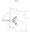
figure 1 , on a représenté en coupe axiale une antenne RF selon un premier mode de réalisation de l'invention. Cette antenne comporte un ensemble constitué d'un réflecteur primaire concave 1 et d'un réflecteur secondaire 2, ainsi que d'un guide d'onde 3 servant en outre de support mécanique au réflecteur secondaire 2. L'ensemble présente une symétrie de révolution autour de l'axe 4. - Le réflecteur primaire 1 peut être en métal à surface réfléchissante, par exemple de l'aluminium- Le guide d'onde 3 peut être par exemple un tube creux métallique, également en aluminium, de section circulaire ayant un diamètre extérieur de 26 mm ou 3,6 mm pour des fréquences d'érnission/réception respectivement de 7 GHz et 60 GHz. Bien entendu le guide d'onde pourrait avoir une section différente, rectangulaire ou carrée par exemple.
- On a représenté le foyer 5 (aussi appelé centre de phase) placé sur l'axe de révolution 4, et la distance focale F 6 qui sépare le foyer du sommet du réflecteur primaire 1. Le réflecteur primaire 1 est par exemple un paraboloïde de révolution autour de l'axe 4 avec une profondeur P 7 et un diamètre D 8.
- Pour une telle antenne présentant un rapport F/D de l'ordre de 0,2, la distance focale F est par exemple de 246 mm et le diamètre D est de 1230 mm (4 pied) Dans ce cas, l'angle d'éclairement limite 2θp du réflecteur primaire vaut 210°.
- La
figure 2 représente le réflecteur secondaire 10 d'une l'antenne selon le premier mode de réalisation de l'invention. Le corps diélectrique 11 du réflecteur secondaire peut être en un matériau diélectrique comme du plastique. La surface interne 12 du réflecteur secondaire 10 peut être une surface de révolution décrite par une équation polynomiale autour d'un l'axe de révolution 13. La surface interne 12 peut être recouverte d'un métal réfléchissant, comme l'argent. - La surface externe 14 du réflecteur secondaire 10 est la surface placée en regard du réflecteur primaire. La surface externe 14 est une surface de révolution autour de l'axe de révolution 13.
- Selon le premier mode de réalisation de l'invention, la surface externe 14 du réflecteur secondaire 10 présente un profil qui est une courbe décrite par une équation polynomiale du sixième degré de la fournie y = ax6 + bx5 + cx4 + dx3 + ex2 + fx + g. Les calculs permettent de montrer que le choix d'un tel profil courbe pour la surface externe 14 permet de réduire les pertes par débordement du double réflecteur.
- La forme de la surface interne du réflecteur secondaire influence l'intensité et la phase de l'onde électromagnétique issue du guide d'onde et reçue par le réflecteur primaire.
- La
figure 3 représente le réflecteur secondaire 20 d'une antenne selon un deuxième mode de réalisation de l'invention. Un relief 21 formant un anneau est ménagé sur la surface externe 22 du réflecteur 20. Le profil de la surface externe 22 de part et d'autre du relief 21 est une courbe décrite par une équation polynomiale du sixième degré de la forme : y = ax6 + bx5 + cx4 + dx3 + ex2 + fx + g - Dans le deuxième mode de réalisation de l'invention, la surface externe 22 du réflecteur 20 est donc constituée de trois parties successives 22a, 21, 22b. Les parties 22a et 22b présentent chacune un profil décrit par une portion de la courbe du sixième degré. Les parties 22a et 22b et le relief 21 présentent une symétrie de révolution autour de l'axe de révolution 23.
- Les pertes par débordement pour le mode émission d'une antenne RF selon le premier mode de réalisation de l'invention sont explicitées sur la
figure 4 . Ces pertes correspondent à des valeurs de l'angle d'éclairement 20 du réflecteur primaire par le réflecteur secondaire pour lesquels les ondes RF issues du guide d'onde 3 sont réfléchies par le réflecteur secondaire 2 dans une direction qui est en dehors du périmètre du réflecteur primaire 1. - Cette figure montre le demi-angle d'éclairement θ (theta) 30 et le demi-angle β (beta) 31, qui est le demi-angle complémentaire du demi-angle θ. Les deux demi-angles θ et β sont mesurés par rapport à l'axe de révolution 4 du réflecteur secondaire 2, et ils ont pour sommet le foyer 5 du réflecteur primaire 1. Il y a perte par débordement pour des valeurs du demi-angle θ supérieures à la valeur limite θp 32 pour laquelle les rayons réfléchis 33 par le réflecteur secondaire viennent à être tangents au bord du réflecteur primaire.
- Les pertes par débordement sont donc dues à tous les rayons 33 réfléchis par le réflecteur secondaire 2 à l'intérieur de la plage angulaire 34. La plage angulaire 34 est définie par deux rayons 35, issus du foyer 5 et symétriques par rapport à l'axe de révolution 4, qui sont tangents aux bords du réflecteur primaire 1.
- La
figure 5 représente une vue en coupe axiale d'une antenne RF selon une variante du premier mode de réalisation de l'invention. Le réflecteur primaire 50 est muni d'une jupe 51 afin de limiter les pertes par débordement. La jupe 51 est un écran recouvert d'un matériau 52 absorbant les ondes RF. Par exemple, la jupe 51 est en aluminium et la couche absorbante 52 est constituée d'une mousse chargée en oxydes de carbone. - La jupe 51 est de hauteur moindre que les jupes utilisées dans l'art antérieur, car les pertes par débordement sont notablement réduites par l'utilisation d'un réflecteur secondaire 53 muni d'une surface externe 54 présentant un profil selon une courbe décrite par une équation polynomiale du sixième degré. On peut optimiser les paramètres de l'équation du sixième degré décrivant le profil de la surface externe 54. Cette optimisation permet de réduire la hauteur de la jupe 51 jusqu'à permettre la réalisation d'une seule pièce du réflecteur primaire 50 et de la jupe 51, comme le montre la
figure 5 . La jupe 51 constitue ainsi une extension du réflecteur primaire 50. Ceci peut être réalisé par exemple en emboutissant une seule plaque d'aluminium de manière à définir successivement ou simultanément la forme, de préférence paraboloïde de révolution, du réflecteur primaire 50 et la forme, de préférence cylindrique, de la jupe 51. - La
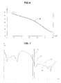
figure 6 représente un exemple de profil 60 de la surface externe du réflecteur secondaire selon un mode particulier de réalisation de l'invention, qui a été obtenu par numérisation du niveau des pertes par débordement. La position des axes X et Y, utilisés respectivement en abscisse et ordonnées, est représentée sur lafigure 2 . Le repère (X, Y) a pour origine un point de l'axe de révolution 13 situé au niveau de la seconde extrémité du réflecteur secondaire 10. l'axe X est aligné sur l'axe de révolution 13 et l'axe Y a une direction perpendiculaire à l'axe de révolution 13. Les distances sont exprimées en centimètres. - L'exempte décrit sur cette figure correspond à une antenne à double réflecteur dont le réflecteur primaire est de type parabolique répondant à l'équation : P/D = D/(16F) dans laquelle P est la profondeur du réflecteur primaire, D est le diamètre du réflecteur primaire, et F est la distance focale du réflecteur primaire.
- Dans cet exempte, F/D=0,25 et le demi-angile d'éclairement limite θp est tel que θp = 90°, car dans toute parabole θp = 2 arc-tangente (D/4F).
- Dans cet exemple de réalisation de l'invention, l'équation polynomiale définissant le profil de la surface externe du réflecteur secondaire est la suivante :

- Les valeurs numériques indiquées ici pour les paramètres a, b, c, d, e, f, g de l'équation du sixième degré dépendent des valeurs numériques choisies pour la distance focale F, la profondeur P et le diamètre D du réflecteur primaire, ainsi que du niveau de pertes par débordement que l'on s'autorise. Si l'on change ces valeurs numériques, on peut trouver une autre ensemble de valeurs pour les paramètres a, b, c, d, e, t, g permettant de minimiser tes pertes par débordement. Ainsi les paramètres a, b, c, d, e, f, g de l'équation du sixième degré peuvent prendre des valeurs différentes.
- La
figure 7 montre le diagramme de rayonnement dans le plan vertical du réflecteur secondaire d'une antenne à double réflecteur pour trois profils différents de la surface externe du réflecteur secondaire : - un profil conique connu de l'art antérieur (courbe de référence 70),
- un profil correspondant au premier mode de réalisation de l'invention (courbe 71), et
- un profil comprenant un relief annelé selon le deuxième mode de réalisation de l'invention (courbe 72).
- Le diagramme de rayonnement est représenté par l'amplitude du rayonnement V exprimée en fonction du demi-angle d'éclairement θ. Ce diagramme de rayonnement est relatif à l'antenne en mode émission. La meilleure conception d'antenne est celle qui permet d'obtenir un rayonnement, ou champ électrique émis, le plus faible possible pour les valeurs de demi-angle d'éclairement θ supérieures à la valeur limite θp représentée ici par la ligne verticale 73. La ligne verticale 73 représente la valeur θp du demi-angle θ qui tangente le bord externe du réflecteur primaire comme montré sur la
figure 4 . Pour des valeurs du demi-angle θ supérieures à la valeur θp définie par la ligne verticale 73, les rayons sont réfléchis dans la plage angulaire 34 et participent aux pertes par débordement. - On observe que la courbe 71, associée au premier mode de réalisation selon l'invention, montre un rayonnement plus faible pour des valeurs de l'angle θ supérieures à la valeur θp que le rayonnement données par la courbe 70 associée à un profil de l'art antérieur. La courbe 72 associée à un deuxième mode de réalisation selon l'invention améliore encore le résultat obtenu avec la courbe 71.
- La
figure 8 , analogue à lafigure 7 , représente le diagramme de rayonnement du réflecteur secondaire, cette fois ci mesurée dans le plan horizontal, pour trois profils différents de la surface externe du réflecteur secondaire : - un profil conique connu de l'art antérieur (courbe de référence 80),
- un profil correspondant au premier mode de réalisation de l'invention (courbe 81), et
- un profil comprenant un relief annelé selon le deuxième mode de réalisation de l'invention (courbe 82).
- Sur cette figure, la ligne verticale 83 représente la valeur θp du demi-angle θ qui tangente le bord externe du réflecteur primaire comme montré sur la
figure 4 . - Comme dans le cas précédent, la meilleure conception d'antenne est celle permettant d'obtenir le rayonnement le plus faible pour les demi-angles 0, supérieurs à la valeur θp, situés à droite de la ligne verticale 83. On observe que la courbe 81 associée au premier mode de réalisation selon l'invention montre des valeurs de rayonnement plus faibles que les valeurs données par la courbe 80 associée à un profil de l'art antérieur. La courbe 82 associée à un deuxième mode de réalisation selon l'invention améliore encore le résultat obtenu avec la courbe 81.
- La
figure 9 montre le diagramme de rayonnement du réflecteur primaire en fonction du demi-angle β d'une antenne à double réflecteur selon l'art antérieur. On a représenté en ordonné les niveaux de puissance réfléchie dans les plans verticaux et horizontaux de l'antenne en fonction du demi-angle β. La courbe 90 correspond à la puissance réfléchie dans le plan vertical, et la courbe 91 correspond à la puissance réfléchie dans le plan horizontal. - Une ligne brisée 92 indique pour chaque valeur du demi-angle β les limites de réflectivité autorisées par la norme ETSI R1C3 Co. Pour une valeur du demi-angle p voisin de 65°, qui est la valeur limite correspondant à la diffraction de l'onde RF sur le bord du réflecteur primaire, l'écart 93 entre la valeur du rayonnement du réflecteur primaire et la valeur limite imposée par la norme est ici de l'ordre de 5 dB.
- La
figure 10 est relative à une antenne à double réflecteur utilisant un réflecteur secondaire selon un premier mode de réalisation de l'invention. La surface externe de l'antenne présente un profil décrit par une équation polynomiale du sixième degré. On a représenté les niveaux de puissance réfléchie dans les plans verticaux et horizontaux de l'antenne en fonction du demi-angle β. La courbe 100 correspond à la puissance réfléchie dans le plan vertical et la courbe 101 correspond à la puissance réfléchie dans le plan horizontal. Une ligne brisée 102 indique, pour chaque valeur du demi-angle β les limites de réflectivité autorisées par la norme ETSI R1C3 Co. - L'écart 103 est ici de l'ordre de 7 dB, en augmentation par rapport à l'écart de 5 dB obtenue pour une antenne de l'art antérieur.
- La
figure 11 est relative à une antenne à double réflecteurs utilisant un réflecteur secondaire selon un deuxième mode de réalisation de l'invention. La surface externe du réflecteur secondaire présente un profil décrit par une équation polynomiale du sixième degré sur lequel a été ajouté un relief annulaire. On a représenté les niveaux de puissance réfléchie dans les plans verticaux et horizontaux de l'antenne en fonction du demi-angle β. La courbe 110 correspond à la puissance réfléchie dans le plan vertical et la courbe 111 correspond à la puissance réfléchie dans le plan horizontal. Une ligne brisée 112 indique, pour chaque valeur du demi-angle β les limites de réflectivité autorisées par la norme ETSI R1C3 Co. - L'écart 113 est de l'ordre de 9 dB, bien supérieure à l'écart 93 de 5 dB obtenu pour une antenne de l'art antérieur et amélioré par rapport à l'écart 103 de 7 dB obtenu selon le premier mode de réalisation de l'invention.
- Plus cet écart entre la valeur du rayonnement du réflecteur primaire et la valeur limite imposée par la norme ETSI R1C3 Co est élevé, plus l'intensité du rayonnement de l'antenne est faible dans cette zone angulaire. Cette qualité de l'antenne est importante pour l'utilisateur car elle assure une pollution électromagnétique moindre des antennes voisines.
Claims (5)
- Réflecteur secondaire d'antenne à double réflecteur comprenant :- une première extrémité ayant une jonction d'un premier diamètre, adaptée pour le couplage à l'extrémité d'un guide d'onde (3),- une seconde extrémité, ayant un second diamètre plus grand que le premier diamètre,- une surface interne (12) convexe réfléchissante placée à la seconde extrémité ayant un axe de révolution (13),- une surface externe (14) de même axe (13), reliant les deux extrémités,- un corps diélectrique (11) s'étendant entre la première et la seconde extrémité et limité par la surface interne (12) et la surface externe (13),caractérisé en ce que la surface externe (14) a un profil convexe décrit par une équation polynomiale du sixième degré de la forme : y = ax6 + bx5 + cx4 + dx3 + ex2 + fx + g où a n'est pas nul.
- Réflecteur secondaire selon la revendication 1, dans lequel la surface externe (22) comporte en outre un relief (21) unique en forme d'anneau entourant le corps diélectrique (11).
- Réflecteur secondaire selon la revendication 2, dans lequel le relief (21) se projette dans une direction perpendiculaire audit axe de révolution (23).
- Antenne à double réflecteur comportant un réflecteur primaire (1) et un réflecteur secondaire (2, 10,) associé, caractérisée en ce que le réflecteur secondaire (2, 10) comprend :- une première extrémité ayant une jonction d'un premier diamètre, adaptée pour le couplage à l'extrémité d'un guide d'onde (3),- une seconde extrémité, ayant un second diamètre plus grand que le premier diamètre,- une surface interne convexe (12) réfléchissante placée à la seconde extrémité ayant un axe de révolution (13),- une surface externe (14) de même axe (13), placée au plus près du réflecteur primaire (1), ayant un profil convexe décrit par une équation polynomiale du sixième degré de la forme : y = ax6 + bx5 + cx4 + dx3 + ex2 + fx + g où a n'est pas nul,- un corps diélectrique (11) s'étendant entre la première et la seconde extrémité et limité par la surface interne (12) et la surface externe (14).
- Antenne à double réflecteur selon la revendication 4, comprenant un réflecteur primaire (50) comportant une jupe, la jupe (51) et le réflecteur primaire (50) étant réalisés d'un seul tenant.
Applications Claiming Priority (1)
| Application Number | Priority Date | Filing Date | Title |
|---|---|---|---|
| FR0850301A FR2926680B1 (fr) | 2008-01-18 | 2008-01-18 | Reflecteur-secondaire d'une antenne a double reflecteur |
Publications (2)
| Publication Number | Publication Date |
|---|---|
| EP2081258A1 true EP2081258A1 (fr) | 2009-07-22 |
| EP2081258B1 EP2081258B1 (fr) | 2011-05-04 |
Family
ID=39700156
Family Applications (1)
| Application Number | Title | Priority Date | Filing Date |
|---|---|---|---|
| EP09150680A Not-in-force EP2081258B1 (fr) | 2008-01-18 | 2009-01-15 | Réflecteur secondaire d'une antenne à double réflecteur |
Country Status (9)
| Country | Link |
|---|---|
| US (1) | US8102324B2 (fr) |
| EP (1) | EP2081258B1 (fr) |
| JP (2) | JP5679820B2 (fr) |
| KR (1) | KR101468889B1 (fr) |
| CN (1) | CN101488606B (fr) |
| AT (1) | ATE508495T1 (fr) |
| DE (1) | DE602009001193D1 (fr) |
| FR (1) | FR2926680B1 (fr) |
| WO (1) | WO2009090195A1 (fr) |
Families Citing this family (164)
| Publication number | Priority date | Publication date | Assignee | Title |
|---|---|---|---|---|
| WO2011099183A1 (fr) * | 2010-02-15 | 2011-08-18 | 日本電気株式会社 | Absorbeur d'ondes radio et antenne parabolique |
| CN101841082A (zh) * | 2010-05-19 | 2010-09-22 | 广东通宇通讯设备有限公司 | 一种微波天线的馈源及微波天线 |
| US8373589B2 (en) * | 2010-05-26 | 2013-02-12 | Detect, Inc. | Rotational parabolic antenna with various feed configurations |
| CN102790288B (zh) * | 2011-05-18 | 2015-03-11 | 深圳光启创新技术有限公司 | 定向天线 |
| US8914258B2 (en) * | 2011-06-28 | 2014-12-16 | Space Systems/Loral, Llc | RF feed element design optimization using secondary pattern |
| US20130057444A1 (en) * | 2011-09-01 | 2013-03-07 | Andrew Llc | Controlled illumination dielectric cone radiator for reflector antenna |
| US8581795B2 (en) | 2011-09-01 | 2013-11-12 | Andrew Llc | Low sidelobe reflector antenna |
| US9019164B2 (en) * | 2011-09-12 | 2015-04-28 | Andrew Llc | Low sidelobe reflector antenna with shield |
| CN103296481B (zh) * | 2012-02-29 | 2017-03-22 | 深圳光启创新技术有限公司 | 一种微波天线系统 |
| CN102683881B (zh) * | 2012-04-28 | 2015-05-27 | 深圳光启高等理工研究院 | 正后馈式卫星电视天线及卫星电视收发系统 |
| CN102868027B (zh) * | 2012-04-28 | 2015-04-22 | 深圳光启高等理工研究院 | 一种偏馈式卫星电视天线及其卫星电视接收系统 |
| CN102810765B (zh) * | 2012-07-31 | 2016-02-10 | 深圳光启创新技术有限公司 | 一种正馈喇叭天线系统 |
| US9113347B2 (en) | 2012-12-05 | 2015-08-18 | At&T Intellectual Property I, Lp | Backhaul link for distributed antenna system |
| US10009065B2 (en) | 2012-12-05 | 2018-06-26 | At&T Intellectual Property I, L.P. | Backhaul link for distributed antenna system |
| US9246233B2 (en) * | 2013-03-01 | 2016-01-26 | Optim Microwave, Inc. | Compact low sidelobe antenna and feed network |
| US9999038B2 (en) | 2013-05-31 | 2018-06-12 | At&T Intellectual Property I, L.P. | Remote distributed antenna system |
| US9525524B2 (en) | 2013-05-31 | 2016-12-20 | At&T Intellectual Property I, L.P. | Remote distributed antenna system |
| US8897697B1 (en) | 2013-11-06 | 2014-11-25 | At&T Intellectual Property I, Lp | Millimeter-wave surface-wave communications |
| US9692101B2 (en) | 2014-08-26 | 2017-06-27 | At&T Intellectual Property I, L.P. | Guided wave couplers for coupling electromagnetic waves between a waveguide surface and a surface of a wire |
| US9768833B2 (en) | 2014-09-15 | 2017-09-19 | At&T Intellectual Property I, L.P. | Method and apparatus for sensing a condition in a transmission medium of electromagnetic waves |
| US10063280B2 (en) | 2014-09-17 | 2018-08-28 | At&T Intellectual Property I, L.P. | Monitoring and mitigating conditions in a communication network |
| US9615269B2 (en) | 2014-10-02 | 2017-04-04 | At&T Intellectual Property I, L.P. | Method and apparatus that provides fault tolerance in a communication network |
| US9685992B2 (en) | 2014-10-03 | 2017-06-20 | At&T Intellectual Property I, L.P. | Circuit panel network and methods thereof |
| US9503189B2 (en) | 2014-10-10 | 2016-11-22 | At&T Intellectual Property I, L.P. | Method and apparatus for arranging communication sessions in a communication system |
| US9973299B2 (en) | 2014-10-14 | 2018-05-15 | At&T Intellectual Property I, L.P. | Method and apparatus for adjusting a mode of communication in a communication network |
| US9762289B2 (en) | 2014-10-14 | 2017-09-12 | At&T Intellectual Property I, L.P. | Method and apparatus for transmitting or receiving signals in a transportation system |
| US9780834B2 (en) | 2014-10-21 | 2017-10-03 | At&T Intellectual Property I, L.P. | Method and apparatus for transmitting electromagnetic waves |
| US9653770B2 (en) | 2014-10-21 | 2017-05-16 | At&T Intellectual Property I, L.P. | Guided wave coupler, coupling module and methods for use therewith |
| US9520945B2 (en) | 2014-10-21 | 2016-12-13 | At&T Intellectual Property I, L.P. | Apparatus for providing communication services and methods thereof |
| US9312919B1 (en) | 2014-10-21 | 2016-04-12 | At&T Intellectual Property I, Lp | Transmission device with impairment compensation and methods for use therewith |
| US9577306B2 (en) | 2014-10-21 | 2017-02-21 | At&T Intellectual Property I, L.P. | Guided-wave transmission device and methods for use therewith |
| US9769020B2 (en) | 2014-10-21 | 2017-09-19 | At&T Intellectual Property I, L.P. | Method and apparatus for responding to events affecting communications in a communication network |
| US9627768B2 (en) | 2014-10-21 | 2017-04-18 | At&T Intellectual Property I, L.P. | Guided-wave transmission device with non-fundamental mode propagation and methods for use therewith |
| US9544006B2 (en) | 2014-11-20 | 2017-01-10 | At&T Intellectual Property I, L.P. | Transmission device with mode division multiplexing and methods for use therewith |
| US10009067B2 (en) | 2014-12-04 | 2018-06-26 | At&T Intellectual Property I, L.P. | Method and apparatus for configuring a communication interface |
| US9800327B2 (en) | 2014-11-20 | 2017-10-24 | At&T Intellectual Property I, L.P. | Apparatus for controlling operations of a communication device and methods thereof |
| US9742462B2 (en) | 2014-12-04 | 2017-08-22 | At&T Intellectual Property I, L.P. | Transmission medium and communication interfaces and methods for use therewith |
| US10340573B2 (en) | 2016-10-26 | 2019-07-02 | At&T Intellectual Property I, L.P. | Launcher with cylindrical coupling device and methods for use therewith |
| US9954287B2 (en) | 2014-11-20 | 2018-04-24 | At&T Intellectual Property I, L.P. | Apparatus for converting wireless signals and electromagnetic waves and methods thereof |
| US9461706B1 (en) | 2015-07-31 | 2016-10-04 | At&T Intellectual Property I, Lp | Method and apparatus for exchanging communication signals |
| US10243784B2 (en) | 2014-11-20 | 2019-03-26 | At&T Intellectual Property I, L.P. | System for generating topology information and methods thereof |
| US9997819B2 (en) | 2015-06-09 | 2018-06-12 | At&T Intellectual Property I, L.P. | Transmission medium and method for facilitating propagation of electromagnetic waves via a core |
| US10144036B2 (en) | 2015-01-30 | 2018-12-04 | At&T Intellectual Property I, L.P. | Method and apparatus for mitigating interference affecting a propagation of electromagnetic waves guided by a transmission medium |
| US9876570B2 (en) | 2015-02-20 | 2018-01-23 | At&T Intellectual Property I, Lp | Guided-wave transmission device with non-fundamental mode propagation and methods for use therewith |
| US9749013B2 (en) | 2015-03-17 | 2017-08-29 | At&T Intellectual Property I, L.P. | Method and apparatus for reducing attenuation of electromagnetic waves guided by a transmission medium |
| US9705561B2 (en) | 2015-04-24 | 2017-07-11 | At&T Intellectual Property I, L.P. | Directional coupling device and methods for use therewith |
| US10224981B2 (en) | 2015-04-24 | 2019-03-05 | At&T Intellectual Property I, Lp | Passive electrical coupling device and methods for use therewith |
| US9793954B2 (en) | 2015-04-28 | 2017-10-17 | At&T Intellectual Property I, L.P. | Magnetic coupling device and methods for use therewith |
| US9948354B2 (en) | 2015-04-28 | 2018-04-17 | At&T Intellectual Property I, L.P. | Magnetic coupling device with reflective plate and methods for use therewith |
| US9871282B2 (en) | 2015-05-14 | 2018-01-16 | At&T Intellectual Property I, L.P. | At least one transmission medium having a dielectric surface that is covered at least in part by a second dielectric |
| US9490869B1 (en) | 2015-05-14 | 2016-11-08 | At&T Intellectual Property I, L.P. | Transmission medium having multiple cores and methods for use therewith |
| US9748626B2 (en) | 2015-05-14 | 2017-08-29 | At&T Intellectual Property I, L.P. | Plurality of cables having different cross-sectional shapes which are bundled together to form a transmission medium |
| US10650940B2 (en) | 2015-05-15 | 2020-05-12 | At&T Intellectual Property I, L.P. | Transmission medium having a conductive material and methods for use therewith |
| US9917341B2 (en) | 2015-05-27 | 2018-03-13 | At&T Intellectual Property I, L.P. | Apparatus and method for launching electromagnetic waves and for modifying radial dimensions of the propagating electromagnetic waves |
| US10812174B2 (en) | 2015-06-03 | 2020-10-20 | At&T Intellectual Property I, L.P. | Client node device and methods for use therewith |
| US9866309B2 (en) | 2015-06-03 | 2018-01-09 | At&T Intellectual Property I, Lp | Host node device and methods for use therewith |
| US10103801B2 (en) | 2015-06-03 | 2018-10-16 | At&T Intellectual Property I, L.P. | Host node device and methods for use therewith |
| US9912381B2 (en) | 2015-06-03 | 2018-03-06 | At&T Intellectual Property I, Lp | Network termination and methods for use therewith |
| US9913139B2 (en) | 2015-06-09 | 2018-03-06 | At&T Intellectual Property I, L.P. | Signal fingerprinting for authentication of communicating devices |
| US9608692B2 (en) | 2015-06-11 | 2017-03-28 | At&T Intellectual Property I, L.P. | Repeater and methods for use therewith |
| US10142086B2 (en) | 2015-06-11 | 2018-11-27 | At&T Intellectual Property I, L.P. | Repeater and methods for use therewith |
| US9820146B2 (en) | 2015-06-12 | 2017-11-14 | At&T Intellectual Property I, L.P. | Method and apparatus for authentication and identity management of communicating devices |
| US9667317B2 (en) | 2015-06-15 | 2017-05-30 | At&T Intellectual Property I, L.P. | Method and apparatus for providing security using network traffic adjustments |
| EP3109941B1 (fr) * | 2015-06-23 | 2019-06-19 | Alcatel- Lucent Shanghai Bell Co., Ltd | Antenne micro onde à double réflecteur |
| US9640850B2 (en) | 2015-06-25 | 2017-05-02 | At&T Intellectual Property I, L.P. | Methods and apparatus for inducing a non-fundamental wave mode on a transmission medium |
| US9509415B1 (en) | 2015-06-25 | 2016-11-29 | At&T Intellectual Property I, L.P. | Methods and apparatus for inducing a fundamental wave mode on a transmission medium |
| US9865911B2 (en) | 2015-06-25 | 2018-01-09 | At&T Intellectual Property I, L.P. | Waveguide system for slot radiating first electromagnetic waves that are combined into a non-fundamental wave mode second electromagnetic wave on a transmission medium |
| US9628116B2 (en) | 2015-07-14 | 2017-04-18 | At&T Intellectual Property I, L.P. | Apparatus and methods for transmitting wireless signals |
| US10044409B2 (en) | 2015-07-14 | 2018-08-07 | At&T Intellectual Property I, L.P. | Transmission medium and methods for use therewith |
| US9853342B2 (en) | 2015-07-14 | 2017-12-26 | At&T Intellectual Property I, L.P. | Dielectric transmission medium connector and methods for use therewith |
| US10148016B2 (en) | 2015-07-14 | 2018-12-04 | At&T Intellectual Property I, L.P. | Apparatus and methods for communicating utilizing an antenna array |
| US9847566B2 (en) | 2015-07-14 | 2017-12-19 | At&T Intellectual Property I, L.P. | Method and apparatus for adjusting a field of a signal to mitigate interference |
| US10170840B2 (en) | 2015-07-14 | 2019-01-01 | At&T Intellectual Property I, L.P. | Apparatus and methods for sending or receiving electromagnetic signals |
| US9722318B2 (en) | 2015-07-14 | 2017-08-01 | At&T Intellectual Property I, L.P. | Method and apparatus for coupling an antenna to a device |
| US10205655B2 (en) | 2015-07-14 | 2019-02-12 | At&T Intellectual Property I, L.P. | Apparatus and methods for communicating utilizing an antenna array and multiple communication paths |
| US10320586B2 (en) | 2015-07-14 | 2019-06-11 | At&T Intellectual Property I, L.P. | Apparatus and methods for generating non-interfering electromagnetic waves on an insulated transmission medium |
| US9882257B2 (en) | 2015-07-14 | 2018-01-30 | At&T Intellectual Property I, L.P. | Method and apparatus for launching a wave mode that mitigates interference |
| US10341142B2 (en) | 2015-07-14 | 2019-07-02 | At&T Intellectual Property I, L.P. | Apparatus and methods for generating non-interfering electromagnetic waves on an uninsulated conductor |
| US10033107B2 (en) | 2015-07-14 | 2018-07-24 | At&T Intellectual Property I, L.P. | Method and apparatus for coupling an antenna to a device |
| US10033108B2 (en) | 2015-07-14 | 2018-07-24 | At&T Intellectual Property I, L.P. | Apparatus and methods for generating an electromagnetic wave having a wave mode that mitigates interference |
| US10090606B2 (en) | 2015-07-15 | 2018-10-02 | At&T Intellectual Property I, L.P. | Antenna system with dielectric array and methods for use therewith |
| US9793951B2 (en) | 2015-07-15 | 2017-10-17 | At&T Intellectual Property I, L.P. | Method and apparatus for launching a wave mode that mitigates interference |
| US9608740B2 (en) | 2015-07-15 | 2017-03-28 | At&T Intellectual Property I, L.P. | Method and apparatus for launching a wave mode that mitigates interference |
| US9749053B2 (en) | 2015-07-23 | 2017-08-29 | At&T Intellectual Property I, L.P. | Node device, repeater and methods for use therewith |
| US9912027B2 (en) | 2015-07-23 | 2018-03-06 | At&T Intellectual Property I, L.P. | Method and apparatus for exchanging communication signals |
| US9871283B2 (en) | 2015-07-23 | 2018-01-16 | At&T Intellectual Property I, Lp | Transmission medium having a dielectric core comprised of plural members connected by a ball and socket configuration |
| US9948333B2 (en) | 2015-07-23 | 2018-04-17 | At&T Intellectual Property I, L.P. | Method and apparatus for wireless communications to mitigate interference |
| US9735833B2 (en) | 2015-07-31 | 2017-08-15 | At&T Intellectual Property I, L.P. | Method and apparatus for communications management in a neighborhood network |
| US9967173B2 (en) | 2015-07-31 | 2018-05-08 | At&T Intellectual Property I, L.P. | Method and apparatus for authentication and identity management of communicating devices |
| US9904535B2 (en) | 2015-09-14 | 2018-02-27 | At&T Intellectual Property I, L.P. | Method and apparatus for distributing software |
| US10079661B2 (en) | 2015-09-16 | 2018-09-18 | At&T Intellectual Property I, L.P. | Method and apparatus for use with a radio distributed antenna system having a clock reference |
| US10009063B2 (en) | 2015-09-16 | 2018-06-26 | At&T Intellectual Property I, L.P. | Method and apparatus for use with a radio distributed antenna system having an out-of-band reference signal |
| US10136434B2 (en) | 2015-09-16 | 2018-11-20 | At&T Intellectual Property I, L.P. | Method and apparatus for use with a radio distributed antenna system having an ultra-wideband control channel |
| US9769128B2 (en) | 2015-09-28 | 2017-09-19 | At&T Intellectual Property I, L.P. | Method and apparatus for encryption of communications over a network |
| US9729197B2 (en) | 2015-10-01 | 2017-08-08 | At&T Intellectual Property I, L.P. | Method and apparatus for communicating network management traffic over a network |
| US9876264B2 (en) | 2015-10-02 | 2018-01-23 | At&T Intellectual Property I, Lp | Communication system, guided wave switch and methods for use therewith |
| US10665942B2 (en) | 2015-10-16 | 2020-05-26 | At&T Intellectual Property I, L.P. | Method and apparatus for adjusting wireless communications |
| US10355367B2 (en) | 2015-10-16 | 2019-07-16 | At&T Intellectual Property I, L.P. | Antenna structure for exchanging wireless signals |
| US9912419B1 (en) | 2016-08-24 | 2018-03-06 | At&T Intellectual Property I, L.P. | Method and apparatus for managing a fault in a distributed antenna system |
| US9860075B1 (en) | 2016-08-26 | 2018-01-02 | At&T Intellectual Property I, L.P. | Method and communication node for broadband distribution |
| US10291311B2 (en) | 2016-09-09 | 2019-05-14 | At&T Intellectual Property I, L.P. | Method and apparatus for mitigating a fault in a distributed antenna system |
| US11032819B2 (en) | 2016-09-15 | 2021-06-08 | At&T Intellectual Property I, L.P. | Method and apparatus for use with a radio distributed antenna system having a control channel reference signal |
| US10340600B2 (en) | 2016-10-18 | 2019-07-02 | At&T Intellectual Property I, L.P. | Apparatus and methods for launching guided waves via plural waveguide systems |
| US10135147B2 (en) | 2016-10-18 | 2018-11-20 | At&T Intellectual Property I, L.P. | Apparatus and methods for launching guided waves via an antenna |
| US10135146B2 (en) | 2016-10-18 | 2018-11-20 | At&T Intellectual Property I, L.P. | Apparatus and methods for launching guided waves via circuits |
| US10374316B2 (en) | 2016-10-21 | 2019-08-06 | At&T Intellectual Property I, L.P. | System and dielectric antenna with non-uniform dielectric |
| US9991580B2 (en) | 2016-10-21 | 2018-06-05 | At&T Intellectual Property I, L.P. | Launcher and coupling system for guided wave mode cancellation |
| US10811767B2 (en) | 2016-10-21 | 2020-10-20 | At&T Intellectual Property I, L.P. | System and dielectric antenna with convex dielectric radome |
| US9876605B1 (en) | 2016-10-21 | 2018-01-23 | At&T Intellectual Property I, L.P. | Launcher and coupling system to support desired guided wave mode |
| US10312567B2 (en) | 2016-10-26 | 2019-06-04 | At&T Intellectual Property I, L.P. | Launcher with planar strip antenna and methods for use therewith |
| US10291334B2 (en) | 2016-11-03 | 2019-05-14 | At&T Intellectual Property I, L.P. | System for detecting a fault in a communication system |
| US10224634B2 (en) | 2016-11-03 | 2019-03-05 | At&T Intellectual Property I, L.P. | Methods and apparatus for adjusting an operational characteristic of an antenna |
| US10225025B2 (en) | 2016-11-03 | 2019-03-05 | At&T Intellectual Property I, L.P. | Method and apparatus for detecting a fault in a communication system |
| US10498044B2 (en) | 2016-11-03 | 2019-12-03 | At&T Intellectual Property I, L.P. | Apparatus for configuring a surface of an antenna |
| US10340601B2 (en) | 2016-11-23 | 2019-07-02 | At&T Intellectual Property I, L.P. | Multi-antenna system and methods for use therewith |
| US10340603B2 (en) | 2016-11-23 | 2019-07-02 | At&T Intellectual Property I, L.P. | Antenna system having shielded structural configurations for assembly |
| US10090594B2 (en) | 2016-11-23 | 2018-10-02 | At&T Intellectual Property I, L.P. | Antenna system having structural configurations for assembly |
| US10178445B2 (en) | 2016-11-23 | 2019-01-08 | At&T Intellectual Property I, L.P. | Methods, devices, and systems for load balancing between a plurality of waveguides |
| US10535928B2 (en) | 2016-11-23 | 2020-01-14 | At&T Intellectual Property I, L.P. | Antenna system and methods for use therewith |
| US10361489B2 (en) | 2016-12-01 | 2019-07-23 | At&T Intellectual Property I, L.P. | Dielectric dish antenna system and methods for use therewith |
| US10305190B2 (en) | 2016-12-01 | 2019-05-28 | At&T Intellectual Property I, L.P. | Reflecting dielectric antenna system and methods for use therewith |
| US10382976B2 (en) | 2016-12-06 | 2019-08-13 | At&T Intellectual Property I, L.P. | Method and apparatus for managing wireless communications based on communication paths and network device positions |
| US10819035B2 (en) | 2016-12-06 | 2020-10-27 | At&T Intellectual Property I, L.P. | Launcher with helical antenna and methods for use therewith |
| US10439675B2 (en) | 2016-12-06 | 2019-10-08 | At&T Intellectual Property I, L.P. | Method and apparatus for repeating guided wave communication signals |
| US10135145B2 (en) | 2016-12-06 | 2018-11-20 | At&T Intellectual Property I, L.P. | Apparatus and methods for generating an electromagnetic wave along a transmission medium |
| US10020844B2 (en) | 2016-12-06 | 2018-07-10 | T&T Intellectual Property I, L.P. | Method and apparatus for broadcast communication via guided waves |
| US10637149B2 (en) | 2016-12-06 | 2020-04-28 | At&T Intellectual Property I, L.P. | Injection molded dielectric antenna and methods for use therewith |
| US9927517B1 (en) | 2016-12-06 | 2018-03-27 | At&T Intellectual Property I, L.P. | Apparatus and methods for sensing rainfall |
| US10755542B2 (en) | 2016-12-06 | 2020-08-25 | At&T Intellectual Property I, L.P. | Method and apparatus for surveillance via guided wave communication |
| US10326494B2 (en) | 2016-12-06 | 2019-06-18 | At&T Intellectual Property I, L.P. | Apparatus for measurement de-embedding and methods for use therewith |
| US10727599B2 (en) | 2016-12-06 | 2020-07-28 | At&T Intellectual Property I, L.P. | Launcher with slot antenna and methods for use therewith |
| US10694379B2 (en) | 2016-12-06 | 2020-06-23 | At&T Intellectual Property I, L.P. | Waveguide system with device-based authentication and methods for use therewith |
| US9893795B1 (en) | 2016-12-07 | 2018-02-13 | At&T Intellectual Property I, Lp | Method and repeater for broadband distribution |
| US10243270B2 (en) | 2016-12-07 | 2019-03-26 | At&T Intellectual Property I, L.P. | Beam adaptive multi-feed dielectric antenna system and methods for use therewith |
| US10168695B2 (en) | 2016-12-07 | 2019-01-01 | At&T Intellectual Property I, L.P. | Method and apparatus for controlling an unmanned aircraft |
| US10139820B2 (en) | 2016-12-07 | 2018-11-27 | At&T Intellectual Property I, L.P. | Method and apparatus for deploying equipment of a communication system |
| US10359749B2 (en) | 2016-12-07 | 2019-07-23 | At&T Intellectual Property I, L.P. | Method and apparatus for utilities management via guided wave communication |
| US10547348B2 (en) | 2016-12-07 | 2020-01-28 | At&T Intellectual Property I, L.P. | Method and apparatus for switching transmission mediums in a communication system |
| US10446936B2 (en) | 2016-12-07 | 2019-10-15 | At&T Intellectual Property I, L.P. | Multi-feed dielectric antenna system and methods for use therewith |
| US10027397B2 (en) | 2016-12-07 | 2018-07-17 | At&T Intellectual Property I, L.P. | Distributed antenna system and methods for use therewith |
| US10389029B2 (en) | 2016-12-07 | 2019-08-20 | At&T Intellectual Property I, L.P. | Multi-feed dielectric antenna system with core selection and methods for use therewith |
| US9998870B1 (en) | 2016-12-08 | 2018-06-12 | At&T Intellectual Property I, L.P. | Method and apparatus for proximity sensing |
| US10411356B2 (en) | 2016-12-08 | 2019-09-10 | At&T Intellectual Property I, L.P. | Apparatus and methods for selectively targeting communication devices with an antenna array |
| US10530505B2 (en) | 2016-12-08 | 2020-01-07 | At&T Intellectual Property I, L.P. | Apparatus and methods for launching electromagnetic waves along a transmission medium |
| US9911020B1 (en) | 2016-12-08 | 2018-03-06 | At&T Intellectual Property I, L.P. | Method and apparatus for tracking via a radio frequency identification device |
| US10069535B2 (en) | 2016-12-08 | 2018-09-04 | At&T Intellectual Property I, L.P. | Apparatus and methods for launching electromagnetic waves having a certain electric field structure |
| US10938108B2 (en) | 2016-12-08 | 2021-03-02 | At&T Intellectual Property I, L.P. | Frequency selective multi-feed dielectric antenna system and methods for use therewith |
| US10916969B2 (en) | 2016-12-08 | 2021-02-09 | At&T Intellectual Property I, L.P. | Method and apparatus for providing power using an inductive coupling |
| US10389037B2 (en) | 2016-12-08 | 2019-08-20 | At&T Intellectual Property I, L.P. | Apparatus and methods for selecting sections of an antenna array and use therewith |
| US10777873B2 (en) | 2016-12-08 | 2020-09-15 | At&T Intellectual Property I, L.P. | Method and apparatus for mounting network devices |
| US10601494B2 (en) | 2016-12-08 | 2020-03-24 | At&T Intellectual Property I, L.P. | Dual-band communication device and method for use therewith |
| US10326689B2 (en) | 2016-12-08 | 2019-06-18 | At&T Intellectual Property I, L.P. | Method and system for providing alternative communication paths |
| US10103422B2 (en) | 2016-12-08 | 2018-10-16 | At&T Intellectual Property I, L.P. | Method and apparatus for mounting network devices |
| US10264586B2 (en) | 2016-12-09 | 2019-04-16 | At&T Mobility Ii Llc | Cloud-based packet controller and methods for use therewith |
| US9838896B1 (en) | 2016-12-09 | 2017-12-05 | At&T Intellectual Property I, L.P. | Method and apparatus for assessing network coverage |
| US10340983B2 (en) | 2016-12-09 | 2019-07-02 | At&T Intellectual Property I, L.P. | Method and apparatus for surveying remote sites via guided wave communications |
| US9973940B1 (en) | 2017-02-27 | 2018-05-15 | At&T Intellectual Property I, L.P. | Apparatus and methods for dynamic impedance matching of a guided wave launcher |
| US10298293B2 (en) | 2017-03-13 | 2019-05-21 | At&T Intellectual Property I, L.P. | Apparatus of communication utilizing wireless network devices |
| US11075466B2 (en) | 2017-08-22 | 2021-07-27 | Commscope Technologies Llc | Parabolic reflector antennas that support low side lobe radiation patterns |
| US11283187B2 (en) * | 2019-02-19 | 2022-03-22 | California Institute Of Technology | Double reflector antenna for miniaturized satellites |
| USD904359S1 (en) * | 2019-03-19 | 2020-12-08 | Telefrontier Co., Ltd. | Dual reflector antenna |
| US11594822B2 (en) | 2020-02-19 | 2023-02-28 | Commscope Technologies Llc | Parabolic reflector antennas with improved cylindrically-shaped shields |
| US11791562B2 (en) * | 2021-02-04 | 2023-10-17 | Orbit Communication Systems Ltd. | Ring focus antenna system with an ultra-wide bandwidth |
| US12183975B2 (en) * | 2022-10-31 | 2024-12-31 | Agency For Defense Development | Antenna apparatus |
Citations (2)
| Publication number | Priority date | Publication date | Assignee | Title |
|---|---|---|---|---|
| GB973583A (en) | 1962-04-11 | 1964-10-28 | Post Office | Improvements in or relating to microwave aerials |
| EP0439800A1 (fr) * | 1990-02-01 | 1991-08-07 | ANT Nachrichtentechnik GmbH | Antenne à double réflecteur |
Family Cites Families (20)
| Publication number | Priority date | Publication date | Assignee | Title |
|---|---|---|---|---|
| US973583A (en) * | 1910-02-12 | 1910-10-25 | William Teeter | Mouse and rat trap. |
| JPS56152301A (en) * | 1980-04-25 | 1981-11-25 | Nec Corp | Dielectric wave director type primary radiator of multiple reflection mirror antenna |
| DE3108758A1 (de) * | 1981-03-07 | 1982-09-16 | Licentia Patent-Verwaltungs-Gmbh, 6000 Frankfurt | Mikrowellen-empfangseinrichtung |
| EP0187800B1 (fr) * | 1984-07-02 | 1990-08-22 | The Marconi Company Limited | Systeme d'antenne du type cassegrain |
| JPS62202605A (ja) * | 1986-02-28 | 1987-09-07 | Nec Corp | 反射鏡アンテナ用一次放射器 |
| US5175562A (en) * | 1989-06-23 | 1992-12-29 | Northeastern University | High aperture-efficient, wide-angle scanning offset reflector antenna |
| JP2710416B2 (ja) * | 1989-07-13 | 1998-02-10 | 日本電気株式会社 | 楕円開口複反射鏡アンテナ |
| JPH0344318U (fr) * | 1989-08-31 | 1991-04-24 | ||
| JPH06222284A (ja) * | 1993-01-22 | 1994-08-12 | Mitsubishi Electric Corp | 板状構造物の形状推定装置及び能動支持装置 |
| JPH07321544A (ja) * | 1994-05-19 | 1995-12-08 | Nec Corp | 多周波数共用アンテナ |
| US6020859A (en) * | 1996-09-26 | 2000-02-01 | Kildal; Per-Simon | Reflector antenna with a self-supported feed |
| EP0859427B1 (fr) * | 1997-02-14 | 2006-06-21 | Andrew A.G. | Antenne hyperfréquence à double réflecteur |
| FR2793073B1 (fr) * | 1999-04-30 | 2003-04-11 | France Telecom | Antenne a reflecteur continu pour reception multiple de faisceaux de satellite |
| US6522305B2 (en) * | 2000-02-25 | 2003-02-18 | Andrew Corporation | Microwave antennas |
| US20030184486A1 (en) * | 2002-03-29 | 2003-10-02 | Lotfollah Shafai | Waveguide back-fire reflector antenna feed |
| US6724349B1 (en) * | 2002-11-12 | 2004-04-20 | L-3 Communications Corporation | Splashplate antenna system with improved waveguide and splashplate (sub-reflector) designs |
| FR2856525B1 (fr) * | 2003-06-17 | 2005-09-02 | Cit Alcatel | Alimentation pour une antenne a reflecteur. |
| US6985120B2 (en) * | 2003-07-25 | 2006-01-10 | Andrew Corporation | Reflector antenna with injection molded feed assembly |
| US6919855B2 (en) * | 2003-09-18 | 2005-07-19 | Andrew Corporation | Tuned perturbation cone feed for reflector antenna |
| JP2005249859A (ja) * | 2004-03-01 | 2005-09-15 | Olympus Corp | 偏心光学系、送光装置、受光装置および光学システム |
-
2008
- 2008-01-18 FR FR0850301A patent/FR2926680B1/fr not_active Expired - Fee Related
-
2009
- 2009-01-14 KR KR1020107018231A patent/KR101468889B1/ko not_active Expired - Fee Related
- 2009-01-14 JP JP2010542620A patent/JP5679820B2/ja not_active Expired - Fee Related
- 2009-01-14 WO PCT/EP2009/050393 patent/WO2009090195A1/fr not_active Ceased
- 2009-01-15 EP EP09150680A patent/EP2081258B1/fr not_active Not-in-force
- 2009-01-15 DE DE602009001193T patent/DE602009001193D1/de active Active
- 2009-01-15 AT AT09150680T patent/ATE508495T1/de not_active IP Right Cessation
- 2009-01-16 US US12/355,114 patent/US8102324B2/en not_active Expired - Fee Related
- 2009-01-19 CN CN2009100048298A patent/CN101488606B/zh not_active Expired - Fee Related
-
2014
- 2014-01-24 JP JP2014010919A patent/JP2014112909A/ja active Pending
Patent Citations (2)
| Publication number | Priority date | Publication date | Assignee | Title |
|---|---|---|---|---|
| GB973583A (en) | 1962-04-11 | 1964-10-28 | Post Office | Improvements in or relating to microwave aerials |
| EP0439800A1 (fr) * | 1990-02-01 | 1991-08-07 | ANT Nachrichtentechnik GmbH | Antenne à double réflecteur |
Also Published As
| Publication number | Publication date |
|---|---|
| KR101468889B1 (ko) | 2014-12-10 |
| US20090184886A1 (en) | 2009-07-23 |
| WO2009090195A1 (fr) | 2009-07-23 |
| DE602009001193D1 (de) | 2011-06-16 |
| JP2014112909A (ja) | 2014-06-19 |
| FR2926680B1 (fr) | 2010-02-12 |
| JP5679820B2 (ja) | 2015-03-04 |
| EP2081258B1 (fr) | 2011-05-04 |
| ATE508495T1 (de) | 2011-05-15 |
| KR20100119550A (ko) | 2010-11-09 |
| CN101488606B (zh) | 2012-07-18 |
| JP2011510550A (ja) | 2011-03-31 |
| US8102324B2 (en) | 2012-01-24 |
| CN101488606A (zh) | 2009-07-22 |
| FR2926680A1 (fr) | 2009-07-24 |
Similar Documents
| Publication | Publication Date | Title |
|---|---|---|
| EP2081258B1 (fr) | Réflecteur secondaire d'une antenne à double réflecteur | |
| EP2264832B1 (fr) | Réflecteur secondaire pour une antenne à double réflecteur | |
| FR2986376A1 (fr) | Reflecteur secondaire d'antenne a double reflecteur | |
| EP1445829B1 (fr) | Réflecteur secondaire pour antenne hyperfréquence de type cassegrain | |
| EP3109941B1 (fr) | Antenne micro onde à double réflecteur | |
| EP1489688B1 (fr) | Alimentation pour une antenne a reflecteur | |
| FR2939970A1 (fr) | Radome pour antenne parabolique large bande. | |
| EP2416449A1 (fr) | Antenne à réflecteur parabolique | |
| FR2845829A1 (fr) | Systeme d'antenne a double reflecteur a foyer en forme d'anneau multi bande | |
| EP2658032B1 (fr) | Cornet d'antenne à grille corruguée | |
| FR2729791A1 (fr) | Dispositif pour diminuer l'effet de radome avec une antenne large bande a rayonnement de surface, et diminuer la surface equivalente refelchissante de l'ensemble | |
| FR2814614A1 (fr) | Lentille divergente a dome pour ondes hyperfrequences et antenne comportant une telle lentille | |
| WO2008037887A2 (fr) | Antenne a materiau bip (bande interdite photonique) systeme | |
| EP0131512A1 (fr) | Antenne à couverture quasi torique à deux réflecteurs | |
| FR2954858A1 (fr) | Antenne rayonnant un signal dans une direction de l'espace dependant de la frequence de ce signal | |
| EP2264833B1 (fr) | Réflecteur secondaire d'antenne parabolique | |
| EP4148902A1 (fr) | Systeme electromagnetique avec deviation angulaire du lobe principal de rayonnement d'une antenne | |
| FR2594260A1 (fr) | Source primaire hyperfrequence pour antenne a balayage conique et antenne l'incorporant. | |
| FR2968848A1 (fr) | Antenne a reflecteur parabolique | |
| EP3264531A1 (fr) | Antenne micro onde à double réflecteur | |
| WO2007006951A1 (fr) | Lentille dielectrique | |
| WO2008065148A2 (fr) | Dispositif d'alimentation d'une antenne à réflecteur | |
| WO2025087979A1 (fr) | Dispositif d'émission/réception à domaine de dépointage étendu | |
| EP3075032B1 (fr) | Structure antennaire compacte pour télécommunications par satellites | |
| EP3075031B1 (fr) | Agencement de structures antennaires pour télécommunications par satellites |
Legal Events
| Date | Code | Title | Description |
|---|---|---|---|
| PUAI | Public reference made under article 153(3) epc to a published international application that has entered the european phase |
Free format text: ORIGINAL CODE: 0009012 |
|
| AK | Designated contracting states |
Kind code of ref document: A1 Designated state(s): AT BE BG CH CY CZ DE DK EE ES FI FR GB GR HR HU IE IS IT LI LT LU LV MC MK MT NL NO PL PT RO SE SI SK TR |
|
| AX | Request for extension of the european patent |
Extension state: AL BA RS |
|
| 17P | Request for examination filed |
Effective date: 20100122 |
|
| 17Q | First examination report despatched |
Effective date: 20100216 |
|
| AKX | Designation fees paid |
Designated state(s): AT BE BG CH CY CZ DE DK EE ES FI FR GB GR HR HU IE IS IT LI LT LU LV MC MK MT NL NO PL PT RO SE SI SK TR |
|
| GRAP | Despatch of communication of intention to grant a patent |
Free format text: ORIGINAL CODE: EPIDOSNIGR1 |
|
| RIN1 | Information on inventor provided before grant (corrected) |
Inventor name: TUAU, DENIS Inventor name: LE BAYON, ARMEL |
|
| GRAS | Grant fee paid |
Free format text: ORIGINAL CODE: EPIDOSNIGR3 |
|
| GRAA | (expected) grant |
Free format text: ORIGINAL CODE: 0009210 |
|
| AK | Designated contracting states |
Kind code of ref document: B1 Designated state(s): AT BE BG CH CY CZ DE DK EE ES FI FR GB GR HR HU IE IS IT LI LT LU LV MC MK MT NL NO PL PT RO SE SI SK TR |
|
| REG | Reference to a national code |
Ref country code: GB Ref legal event code: FG4D Free format text: NOT ENGLISH |
|
| REG | Reference to a national code |
Ref country code: CH Ref legal event code: EP |
|
| REG | Reference to a national code |
Ref country code: IE Ref legal event code: FG4D Free format text: LANGUAGE OF EP DOCUMENT: FRENCH |
|
| REF | Corresponds to: |
Ref document number: 602009001193 Country of ref document: DE Date of ref document: 20110616 Kind code of ref document: P |
|
| REG | Reference to a national code |
Ref country code: DE Ref legal event code: R096 Ref document number: 602009001193 Country of ref document: DE Effective date: 20110616 |
|
| REG | Reference to a national code |
Ref country code: NL Ref legal event code: VDEP Effective date: 20110504 |
|
| PG25 | Lapsed in a contracting state [announced via postgrant information from national office to epo] |
Ref country code: NO Free format text: LAPSE BECAUSE OF FAILURE TO SUBMIT A TRANSLATION OF THE DESCRIPTION OR TO PAY THE FEE WITHIN THE PRESCRIBED TIME-LIMIT Effective date: 20110804 Ref country code: LT Free format text: LAPSE BECAUSE OF FAILURE TO SUBMIT A TRANSLATION OF THE DESCRIPTION OR TO PAY THE FEE WITHIN THE PRESCRIBED TIME-LIMIT Effective date: 20110504 Ref country code: PT Free format text: LAPSE BECAUSE OF FAILURE TO SUBMIT A TRANSLATION OF THE DESCRIPTION OR TO PAY THE FEE WITHIN THE PRESCRIBED TIME-LIMIT Effective date: 20110905 Ref country code: SE Free format text: LAPSE BECAUSE OF FAILURE TO SUBMIT A TRANSLATION OF THE DESCRIPTION OR TO PAY THE FEE WITHIN THE PRESCRIBED TIME-LIMIT Effective date: 20110504 |
|
| PG25 | Lapsed in a contracting state [announced via postgrant information from national office to epo] |
Ref country code: SI Free format text: LAPSE BECAUSE OF FAILURE TO SUBMIT A TRANSLATION OF THE DESCRIPTION OR TO PAY THE FEE WITHIN THE PRESCRIBED TIME-LIMIT Effective date: 20110504 Ref country code: ES Free format text: LAPSE BECAUSE OF FAILURE TO SUBMIT A TRANSLATION OF THE DESCRIPTION OR TO PAY THE FEE WITHIN THE PRESCRIBED TIME-LIMIT Effective date: 20110815 Ref country code: GR Free format text: LAPSE BECAUSE OF FAILURE TO SUBMIT A TRANSLATION OF THE DESCRIPTION OR TO PAY THE FEE WITHIN THE PRESCRIBED TIME-LIMIT Effective date: 20110805 Ref country code: IS Free format text: LAPSE BECAUSE OF FAILURE TO SUBMIT A TRANSLATION OF THE DESCRIPTION OR TO PAY THE FEE WITHIN THE PRESCRIBED TIME-LIMIT Effective date: 20110904 Ref country code: LV Free format text: LAPSE BECAUSE OF FAILURE TO SUBMIT A TRANSLATION OF THE DESCRIPTION OR TO PAY THE FEE WITHIN THE PRESCRIBED TIME-LIMIT Effective date: 20110504 Ref country code: AT Free format text: LAPSE BECAUSE OF FAILURE TO SUBMIT A TRANSLATION OF THE DESCRIPTION OR TO PAY THE FEE WITHIN THE PRESCRIBED TIME-LIMIT Effective date: 20110504 Ref country code: FI Free format text: LAPSE BECAUSE OF FAILURE TO SUBMIT A TRANSLATION OF THE DESCRIPTION OR TO PAY THE FEE WITHIN THE PRESCRIBED TIME-LIMIT Effective date: 20110504 Ref country code: CY Free format text: LAPSE BECAUSE OF FAILURE TO SUBMIT A TRANSLATION OF THE DESCRIPTION OR TO PAY THE FEE WITHIN THE PRESCRIBED TIME-LIMIT Effective date: 20110504 |
|
| REG | Reference to a national code |
Ref country code: IE Ref legal event code: FD4D |
|
| PG25 | Lapsed in a contracting state [announced via postgrant information from national office to epo] |
Ref country code: NL Free format text: LAPSE BECAUSE OF FAILURE TO SUBMIT A TRANSLATION OF THE DESCRIPTION OR TO PAY THE FEE WITHIN THE PRESCRIBED TIME-LIMIT Effective date: 20110504 |
|
| PG25 | Lapsed in a contracting state [announced via postgrant information from national office to epo] |
Ref country code: EE Free format text: LAPSE BECAUSE OF FAILURE TO SUBMIT A TRANSLATION OF THE DESCRIPTION OR TO PAY THE FEE WITHIN THE PRESCRIBED TIME-LIMIT Effective date: 20110504 Ref country code: CZ Free format text: LAPSE BECAUSE OF FAILURE TO SUBMIT A TRANSLATION OF THE DESCRIPTION OR TO PAY THE FEE WITHIN THE PRESCRIBED TIME-LIMIT Effective date: 20110504 Ref country code: IE Free format text: LAPSE BECAUSE OF FAILURE TO SUBMIT A TRANSLATION OF THE DESCRIPTION OR TO PAY THE FEE WITHIN THE PRESCRIBED TIME-LIMIT Effective date: 20110504 |
|
| RAP2 | Party data changed (patent owner data changed or rights of a patent transferred) |
Owner name: ALCATEL LUCENT |
|
| PG25 | Lapsed in a contracting state [announced via postgrant information from national office to epo] |
Ref country code: RO Free format text: LAPSE BECAUSE OF FAILURE TO SUBMIT A TRANSLATION OF THE DESCRIPTION OR TO PAY THE FEE WITHIN THE PRESCRIBED TIME-LIMIT Effective date: 20110504 Ref country code: PL Free format text: LAPSE BECAUSE OF FAILURE TO SUBMIT A TRANSLATION OF THE DESCRIPTION OR TO PAY THE FEE WITHIN THE PRESCRIBED TIME-LIMIT Effective date: 20110504 Ref country code: DK Free format text: LAPSE BECAUSE OF FAILURE TO SUBMIT A TRANSLATION OF THE DESCRIPTION OR TO PAY THE FEE WITHIN THE PRESCRIBED TIME-LIMIT Effective date: 20110504 Ref country code: SK Free format text: LAPSE BECAUSE OF FAILURE TO SUBMIT A TRANSLATION OF THE DESCRIPTION OR TO PAY THE FEE WITHIN THE PRESCRIBED TIME-LIMIT Effective date: 20110504 |
|
| REG | Reference to a national code |
Ref country code: CH Ref legal event code: PCOW Free format text: ALCATEL LUCENT;3, AVENUE OCTAVE GREARD;75007 PARIS (FR) |
|
| PLBE | No opposition filed within time limit |
Free format text: ORIGINAL CODE: 0009261 |
|
| STAA | Information on the status of an ep patent application or granted ep patent |
Free format text: STATUS: NO OPPOSITION FILED WITHIN TIME LIMIT |
|
| 26N | No opposition filed |
Effective date: 20120207 |
|
| PG25 | Lapsed in a contracting state [announced via postgrant information from national office to epo] |
Ref country code: HR Free format text: LAPSE BECAUSE OF FAILURE TO SUBMIT A TRANSLATION OF THE DESCRIPTION OR TO PAY THE FEE WITHIN THE PRESCRIBED TIME-LIMIT Effective date: 20111123 Ref country code: IT Free format text: LAPSE BECAUSE OF FAILURE TO SUBMIT A TRANSLATION OF THE DESCRIPTION OR TO PAY THE FEE WITHIN THE PRESCRIBED TIME-LIMIT Effective date: 20110504 |
|
| REG | Reference to a national code |
Ref country code: DE Ref legal event code: R097 Ref document number: 602009001193 Country of ref document: DE Effective date: 20120207 |
|
| BERE | Be: lapsed |
Owner name: ALCATEL LUCENT Effective date: 20120131 |
|
| PG25 | Lapsed in a contracting state [announced via postgrant information from national office to epo] |
Ref country code: MC Free format text: LAPSE BECAUSE OF NON-PAYMENT OF DUE FEES Effective date: 20120131 |
|
| PG25 | Lapsed in a contracting state [announced via postgrant information from national office to epo] |
Ref country code: BE Free format text: LAPSE BECAUSE OF NON-PAYMENT OF DUE FEES Effective date: 20120131 |
|
| PG25 | Lapsed in a contracting state [announced via postgrant information from national office to epo] |
Ref country code: MK Free format text: LAPSE BECAUSE OF FAILURE TO SUBMIT A TRANSLATION OF THE DESCRIPTION OR TO PAY THE FEE WITHIN THE PRESCRIBED TIME-LIMIT Effective date: 20110504 |
|
| PG25 | Lapsed in a contracting state [announced via postgrant information from national office to epo] |
Ref country code: BG Free format text: LAPSE BECAUSE OF FAILURE TO SUBMIT A TRANSLATION OF THE DESCRIPTION OR TO PAY THE FEE WITHIN THE PRESCRIBED TIME-LIMIT Effective date: 20110804 |
|
| PG25 | Lapsed in a contracting state [announced via postgrant information from national office to epo] |
Ref country code: MT Free format text: LAPSE BECAUSE OF FAILURE TO SUBMIT A TRANSLATION OF THE DESCRIPTION OR TO PAY THE FEE WITHIN THE PRESCRIBED TIME-LIMIT Effective date: 20110504 |
|
| REG | Reference to a national code |
Ref country code: CH Ref legal event code: PL |
|
| REG | Reference to a national code |
Ref country code: GB Ref legal event code: 732E Free format text: REGISTERED BETWEEN 20130926 AND 20131002 |
|
| PG25 | Lapsed in a contracting state [announced via postgrant information from national office to epo] |
Ref country code: LI Free format text: LAPSE BECAUSE OF NON-PAYMENT OF DUE FEES Effective date: 20130131 Ref country code: CH Free format text: LAPSE BECAUSE OF NON-PAYMENT OF DUE FEES Effective date: 20130131 |
|
| REG | Reference to a national code |
Ref country code: FR Ref legal event code: GC Effective date: 20131018 |
|
| PG25 | Lapsed in a contracting state [announced via postgrant information from national office to epo] |
Ref country code: HR Free format text: LAPSE BECAUSE OF FAILURE TO SUBMIT A TRANSLATION OF THE DESCRIPTION OR TO PAY THE FEE WITHIN THE PRESCRIBED TIME-LIMIT Effective date: 20110504 |
|
| PG25 | Lapsed in a contracting state [announced via postgrant information from national office to epo] |
Ref country code: TR Free format text: LAPSE BECAUSE OF FAILURE TO SUBMIT A TRANSLATION OF THE DESCRIPTION OR TO PAY THE FEE WITHIN THE PRESCRIBED TIME-LIMIT Effective date: 20110504 |
|
| PG25 | Lapsed in a contracting state [announced via postgrant information from national office to epo] |
Ref country code: LU Free format text: LAPSE BECAUSE OF NON-PAYMENT OF DUE FEES Effective date: 20120115 |
|
| PG25 | Lapsed in a contracting state [announced via postgrant information from national office to epo] |
Ref country code: HU Free format text: LAPSE BECAUSE OF FAILURE TO SUBMIT A TRANSLATION OF THE DESCRIPTION OR TO PAY THE FEE WITHIN THE PRESCRIBED TIME-LIMIT Effective date: 20090115 |
|
| REG | Reference to a national code |
Ref country code: FR Ref legal event code: RG Effective date: 20141016 |
|
| REG | Reference to a national code |
Ref country code: FR Ref legal event code: PLFP Year of fee payment: 7 |
|
| REG | Reference to a national code |
Ref country code: FR Ref legal event code: PLFP Year of fee payment: 8 |
|
| REG | Reference to a national code |
Ref country code: FR Ref legal event code: PLFP Year of fee payment: 9 |
|
| PGFP | Annual fee paid to national office [announced via postgrant information from national office to epo] |
Ref country code: FR Payment date: 20170120 Year of fee payment: 9 Ref country code: DE Payment date: 20170120 Year of fee payment: 9 |
|
| PGFP | Annual fee paid to national office [announced via postgrant information from national office to epo] |
Ref country code: GB Payment date: 20170119 Year of fee payment: 9 |
|
| REG | Reference to a national code |
Ref country code: DE Ref legal event code: R119 Ref document number: 602009001193 Country of ref document: DE |
|
| GBPC | Gb: european patent ceased through non-payment of renewal fee |
Effective date: 20180115 |
|
| PG25 | Lapsed in a contracting state [announced via postgrant information from national office to epo] |
Ref country code: FR Free format text: LAPSE BECAUSE OF NON-PAYMENT OF DUE FEES Effective date: 20180131 Ref country code: DE Free format text: LAPSE BECAUSE OF NON-PAYMENT OF DUE FEES Effective date: 20180801 |
|
| REG | Reference to a national code |
Ref country code: FR Ref legal event code: ST Effective date: 20180928 |
|
| PG25 | Lapsed in a contracting state [announced via postgrant information from national office to epo] |
Ref country code: GB Free format text: LAPSE BECAUSE OF NON-PAYMENT OF DUE FEES Effective date: 20180115 |
|
| REG | Reference to a national code |
Ref country code: DE Ref legal event code: R073 Ref document number: 602009001193 Country of ref document: DE |
|
| REG | Reference to a national code |
Ref country code: DE Ref legal event code: R082 Ref document number: 602009001193 Country of ref document: DE Ref country code: DE Ref legal event code: R081 Ref document number: 602009001193 Country of ref document: DE Owner name: PROVENANCE ASSET GROUP LLC, PITTSFORD, US Free format text: FORMER OWNER: ALCATEL LUCENT, PARIS, FR |
|
| REG | Reference to a national code |
Ref country code: DE Ref legal event code: R124 Ref document number: 602009001193 Country of ref document: DE |