EP2081058A2 - Sperrstruktur mit Oberflächenrelief - Google Patents
Sperrstruktur mit Oberflächenrelief Download PDFInfo
- Publication number
- EP2081058A2 EP2081058A2 EP09150663A EP09150663A EP2081058A2 EP 2081058 A2 EP2081058 A2 EP 2081058A2 EP 09150663 A EP09150663 A EP 09150663A EP 09150663 A EP09150663 A EP 09150663A EP 2081058 A2 EP2081058 A2 EP 2081058A2
- Authority
- EP
- European Patent Office
- Prior art keywords
- layer
- surface relief
- coating
- scratch
- around
- Prior art date
- Legal status (The legal status is an assumption and is not a legal conclusion. Google has not performed a legal analysis and makes no representation as to the accuracy of the status listed.)
- Granted
Links
- 230000004888 barrier function Effects 0.000 title claims description 143
- 239000002245 particle Substances 0.000 claims abstract description 62
- 238000000034 method Methods 0.000 claims description 164
- 239000011888 foil Substances 0.000 claims description 132
- 229910052751 metal Inorganic materials 0.000 claims description 79
- 239000002184 metal Substances 0.000 claims description 79
- 239000000463 material Substances 0.000 claims description 50
- 239000000853 adhesive Substances 0.000 claims description 40
- 230000001070 adhesive effect Effects 0.000 claims description 39
- 230000008569 process Effects 0.000 claims description 37
- 238000004049 embossing Methods 0.000 claims description 36
- 229910044991 metal oxide Inorganic materials 0.000 claims description 36
- 150000004706 metal oxides Chemical class 0.000 claims description 36
- 238000007756 gravure coating Methods 0.000 claims description 26
- 239000000203 mixture Substances 0.000 claims description 26
- 238000009472 formulation Methods 0.000 claims description 23
- 239000011230 binding agent Substances 0.000 claims description 16
- 229920000642 polymer Polymers 0.000 claims description 15
- PNEYBMLMFCGWSK-UHFFFAOYSA-N Alumina Chemical compound [O-2].[O-2].[O-2].[Al+3].[Al+3] PNEYBMLMFCGWSK-UHFFFAOYSA-N 0.000 claims description 14
- GWEVSGVZZGPLCZ-UHFFFAOYSA-N Titan oxide Chemical compound O=[Ti]=O GWEVSGVZZGPLCZ-UHFFFAOYSA-N 0.000 claims description 12
- VTYYLEPIZMXCLO-UHFFFAOYSA-L Calcium carbonate Chemical compound [Ca+2].[O-]C([O-])=O VTYYLEPIZMXCLO-UHFFFAOYSA-L 0.000 claims description 10
- NIXOWILDQLNWCW-UHFFFAOYSA-M Acrylate Chemical compound [O-]C(=O)C=C NIXOWILDQLNWCW-UHFFFAOYSA-M 0.000 claims description 6
- 229910010293 ceramic material Inorganic materials 0.000 claims description 6
- 239000004408 titanium dioxide Substances 0.000 claims description 6
- 229910000019 calcium carbonate Inorganic materials 0.000 claims description 5
- 238000000151 deposition Methods 0.000 claims description 5
- 239000010410 layer Substances 0.000 description 477
- 238000000576 coating method Methods 0.000 description 163
- 239000011248 coating agent Substances 0.000 description 147
- 125000006850 spacer group Chemical group 0.000 description 110
- 230000003287 optical effect Effects 0.000 description 56
- 239000000758 substrate Substances 0.000 description 48
- 239000004411 aluminium Substances 0.000 description 45
- 229910052782 aluminium Inorganic materials 0.000 description 45
- 239000000945 filler Substances 0.000 description 44
- XAGFODPZIPBFFR-UHFFFAOYSA-N aluminium Chemical compound [Al] XAGFODPZIPBFFR-UHFFFAOYSA-N 0.000 description 42
- 239000010408 film Substances 0.000 description 41
- 238000001465 metallisation Methods 0.000 description 38
- 238000001035 drying Methods 0.000 description 32
- 239000007789 gas Substances 0.000 description 29
- 238000009792 diffusion process Methods 0.000 description 27
- 239000011295 pitch Substances 0.000 description 26
- 230000005540 biological transmission Effects 0.000 description 23
- 239000004922 lacquer Substances 0.000 description 23
- 238000012546 transfer Methods 0.000 description 23
- 230000000694 effects Effects 0.000 description 20
- 239000007769 metal material Substances 0.000 description 19
- 238000005452 bending Methods 0.000 description 17
- 238000004519 manufacturing process Methods 0.000 description 15
- 238000000465 moulding Methods 0.000 description 15
- 238000005266 casting Methods 0.000 description 14
- 238000007646 gravure printing Methods 0.000 description 14
- 230000001965 increasing effect Effects 0.000 description 14
- 238000005336 cracking Methods 0.000 description 13
- 230000008901 benefit Effects 0.000 description 10
- 239000008199 coating composition Substances 0.000 description 10
- 239000007787 solid Substances 0.000 description 10
- 230000007704 transition Effects 0.000 description 10
- 239000001993 wax Substances 0.000 description 10
- 230000000903 blocking effect Effects 0.000 description 9
- 239000007788 liquid Substances 0.000 description 9
- 238000005299 abrasion Methods 0.000 description 8
- 239000000976 ink Substances 0.000 description 8
- 239000004033 plastic Substances 0.000 description 8
- 229920003023 plastic Polymers 0.000 description 8
- 238000012876 topography Methods 0.000 description 8
- 238000001723 curing Methods 0.000 description 6
- 230000000737 periodic effect Effects 0.000 description 6
- 239000002491 polymer binding agent Substances 0.000 description 6
- 238000007639 printing Methods 0.000 description 6
- 230000000007 visual effect Effects 0.000 description 6
- 239000002131 composite material Substances 0.000 description 5
- 238000010586 diagram Methods 0.000 description 5
- 238000011065 in-situ storage Methods 0.000 description 5
- 230000033001 locomotion Effects 0.000 description 5
- 230000014759 maintenance of location Effects 0.000 description 5
- 241001085205 Prenanthella exigua Species 0.000 description 4
- 230000000295 complement effect Effects 0.000 description 4
- 230000004907 flux Effects 0.000 description 4
- 238000004806 packaging method and process Methods 0.000 description 4
- 238000006748 scratching Methods 0.000 description 4
- 230000002393 scratching effect Effects 0.000 description 4
- 239000002356 single layer Substances 0.000 description 4
- 230000003746 surface roughness Effects 0.000 description 4
- 229920000134 Metallised film Polymers 0.000 description 3
- 229920001971 elastomer Polymers 0.000 description 3
- 238000005516 engineering process Methods 0.000 description 3
- 238000005286 illumination Methods 0.000 description 3
- 229920000126 latex Polymers 0.000 description 3
- 239000004816 latex Substances 0.000 description 3
- 230000031700 light absorption Effects 0.000 description 3
- 239000011104 metalized film Substances 0.000 description 3
- 150000002739 metals Chemical class 0.000 description 3
- 238000000059 patterning Methods 0.000 description 3
- 238000002310 reflectometry Methods 0.000 description 3
- 239000005060 rubber Substances 0.000 description 3
- 239000002904 solvent Substances 0.000 description 3
- 239000000126 substance Substances 0.000 description 3
- 238000003853 Pinholing Methods 0.000 description 2
- 238000003848 UV Light-Curing Methods 0.000 description 2
- 239000005083 Zinc sulfide Substances 0.000 description 2
- 238000010521 absorption reaction Methods 0.000 description 2
- 230000003213 activating effect Effects 0.000 description 2
- 239000000654 additive Substances 0.000 description 2
- 239000012790 adhesive layer Substances 0.000 description 2
- 238000007605 air drying Methods 0.000 description 2
- 238000000637 aluminium metallisation Methods 0.000 description 2
- 230000015572 biosynthetic process Effects 0.000 description 2
- 150000001875 compounds Chemical group 0.000 description 2
- 238000013461 design Methods 0.000 description 2
- 229910003460 diamond Inorganic materials 0.000 description 2
- 239000010432 diamond Substances 0.000 description 2
- 210000004905 finger nail Anatomy 0.000 description 2
- 238000010348 incorporation Methods 0.000 description 2
- 238000002372 labelling Methods 0.000 description 2
- 238000003475 lamination Methods 0.000 description 2
- 230000007246 mechanism Effects 0.000 description 2
- 238000002844 melting Methods 0.000 description 2
- 230000008018 melting Effects 0.000 description 2
- 239000002923 metal particle Substances 0.000 description 2
- 230000009467 reduction Effects 0.000 description 2
- 238000007788 roughening Methods 0.000 description 2
- 230000009974 thixotropic effect Effects 0.000 description 2
- 238000001771 vacuum deposition Methods 0.000 description 2
- 238000012800 visualization Methods 0.000 description 2
- DRDVZXDWVBGGMH-UHFFFAOYSA-N zinc;sulfide Chemical compound [S-2].[Zn+2] DRDVZXDWVBGGMH-UHFFFAOYSA-N 0.000 description 2
- 229910017107 AlOx Inorganic materials 0.000 description 1
- 241000167857 Bourreria Species 0.000 description 1
- 239000006096 absorbing agent Substances 0.000 description 1
- 230000009471 action Effects 0.000 description 1
- 238000005054 agglomeration Methods 0.000 description 1
- 230000002776 aggregation Effects 0.000 description 1
- 230000004075 alteration Effects 0.000 description 1
- 230000003466 anti-cipated effect Effects 0.000 description 1
- 238000013459 approach Methods 0.000 description 1
- 238000000149 argon plasma sintering Methods 0.000 description 1
- QVGXLLKOCUKJST-UHFFFAOYSA-N atomic oxygen Chemical compound [O] QVGXLLKOCUKJST-UHFFFAOYSA-N 0.000 description 1
- 239000000919 ceramic Substances 0.000 description 1
- 239000011247 coating layer Substances 0.000 description 1
- 239000012141 concentrate Substances 0.000 description 1
- 238000004132 cross linking Methods 0.000 description 1
- 230000003247 decreasing effect Effects 0.000 description 1
- 230000032798 delamination Effects 0.000 description 1
- 230000001419 dependent effect Effects 0.000 description 1
- 230000008021 deposition Effects 0.000 description 1
- 239000006185 dispersion Substances 0.000 description 1
- 238000009826 distribution Methods 0.000 description 1
- 230000009977 dual effect Effects 0.000 description 1
- 230000002708 enhancing effect Effects 0.000 description 1
- 238000001704 evaporation Methods 0.000 description 1
- 239000011521 glass Substances 0.000 description 1
- 230000006872 improvement Effects 0.000 description 1
- 238000007373 indentation Methods 0.000 description 1
- 239000011229 interlayer Substances 0.000 description 1
- 238000003754 machining Methods 0.000 description 1
- 238000012423 maintenance Methods 0.000 description 1
- 239000011159 matrix material Substances 0.000 description 1
- 239000012528 membrane Substances 0.000 description 1
- 239000013528 metallic particle Substances 0.000 description 1
- 238000012634 optical imaging Methods 0.000 description 1
- 230000003647 oxidation Effects 0.000 description 1
- 238000007254 oxidation reaction Methods 0.000 description 1
- 239000001301 oxygen Substances 0.000 description 1
- 229910052760 oxygen Inorganic materials 0.000 description 1
- 239000011236 particulate material Substances 0.000 description 1
- 230000035699 permeability Effects 0.000 description 1
- 229920000058 polyacrylate Polymers 0.000 description 1
- 229920002635 polyurethane Polymers 0.000 description 1
- 239000004814 polyurethane Substances 0.000 description 1
- 238000012545 processing Methods 0.000 description 1
- 238000003847 radiation curing Methods 0.000 description 1
- 238000009877 rendering Methods 0.000 description 1
- 230000010076 replication Effects 0.000 description 1
- 239000011347 resin Substances 0.000 description 1
- 229920005989 resin Polymers 0.000 description 1
- 230000000717 retained effect Effects 0.000 description 1
- 238000007790 scraping Methods 0.000 description 1
- 230000009291 secondary effect Effects 0.000 description 1
- 239000007779 soft material Substances 0.000 description 1
- 238000009494 specialized coating Methods 0.000 description 1
- 239000012798 spherical particle Substances 0.000 description 1
- 239000000725 suspension Substances 0.000 description 1
- 229920001169 thermoplastic Polymers 0.000 description 1
- 239000004416 thermosoftening plastic Substances 0.000 description 1
- XLYOFNOQVPJJNP-UHFFFAOYSA-N water Substances O XLYOFNOQVPJJNP-UHFFFAOYSA-N 0.000 description 1
- 238000009736 wetting Methods 0.000 description 1
- 230000003245 working effect Effects 0.000 description 1
Images


Classifications
-
- B—PERFORMING OPERATIONS; TRANSPORTING
- B42—BOOKBINDING; ALBUMS; FILES; SPECIAL PRINTED MATTER
- B42D—BOOKS; BOOK COVERS; LOOSE LEAVES; PRINTED MATTER CHARACTERISED BY IDENTIFICATION OR SECURITY FEATURES; PRINTED MATTER OF SPECIAL FORMAT OR STYLE NOT OTHERWISE PROVIDED FOR; DEVICES FOR USE THEREWITH AND NOT OTHERWISE PROVIDED FOR; MOVABLE-STRIP WRITING OR READING APPARATUS
- B42D15/00—Printed matter of special format or style not otherwise provided for
- B42D15/02—Postcards; Greeting, menu, business or like cards; Letter cards or letter-sheets
- B42D15/025—Postcards; Greeting, menu, business or like cards; Letter cards or letter-sheets with peel-away layer hiding information
-
- B—PERFORMING OPERATIONS; TRANSPORTING
- B32—LAYERED PRODUCTS
- B32B—LAYERED PRODUCTS, i.e. PRODUCTS BUILT-UP OF STRATA OF FLAT OR NON-FLAT, e.g. CELLULAR OR HONEYCOMB, FORM
- B32B15/00—Layered products comprising a layer of metal
-
- B—PERFORMING OPERATIONS; TRANSPORTING
- B32—LAYERED PRODUCTS
- B32B—LAYERED PRODUCTS, i.e. PRODUCTS BUILT-UP OF STRATA OF FLAT OR NON-FLAT, e.g. CELLULAR OR HONEYCOMB, FORM
- B32B3/00—Layered products comprising a layer with external or internal discontinuities or unevennesses, or a layer of non-planar shape; Layered products comprising a layer having particular features of form
-
- B—PERFORMING OPERATIONS; TRANSPORTING
- B41—PRINTING; LINING MACHINES; TYPEWRITERS; STAMPS
- B41M—PRINTING, DUPLICATING, MARKING, OR COPYING PROCESSES; COLOUR PRINTING
- B41M3/00—Printing processes to produce particular kinds of printed work, e.g. patterns
- B41M3/14—Security printing
-
- B—PERFORMING OPERATIONS; TRANSPORTING
- B42—BOOKBINDING; ALBUMS; FILES; SPECIAL PRINTED MATTER
- B42D—BOOKS; BOOK COVERS; LOOSE LEAVES; PRINTED MATTER CHARACTERISED BY IDENTIFICATION OR SECURITY FEATURES; PRINTED MATTER OF SPECIAL FORMAT OR STYLE NOT OTHERWISE PROVIDED FOR; DEVICES FOR USE THEREWITH AND NOT OTHERWISE PROVIDED FOR; MOVABLE-STRIP WRITING OR READING APPARATUS
- B42D15/00—Printed matter of special format or style not otherwise provided for
-
- B—PERFORMING OPERATIONS; TRANSPORTING
- B44—DECORATIVE ARTS
- B44F—SPECIAL DESIGNS OR PICTURES
- B44F1/00—Designs or pictures characterised by special or unusual light effects
- B44F1/06—Designs or pictures characterised by special or unusual light effects produced by transmitted light, e.g. transparencies, imitations of glass paintings
-
- B—PERFORMING OPERATIONS; TRANSPORTING
- B65—CONVEYING; PACKING; STORING; HANDLING THIN OR FILAMENTARY MATERIAL
- B65D—CONTAINERS FOR STORAGE OR TRANSPORT OF ARTICLES OR MATERIALS, e.g. BAGS, BARRELS, BOTTLES, BOXES, CANS, CARTONS, CRATES, DRUMS, JARS, TANKS, HOPPERS, FORWARDING CONTAINERS; ACCESSORIES, CLOSURES, OR FITTINGS THEREFOR; PACKAGING ELEMENTS; PACKAGES
- B65D65/00—Wrappers or flexible covers; Packaging materials of special type or form
-
- G—PHYSICS
- G02—OPTICS
- G02B—OPTICAL ELEMENTS, SYSTEMS OR APPARATUS
- G02B5/00—Optical elements other than lenses
- G02B5/02—Diffusing elements; Afocal elements
- G02B5/0205—Diffusing elements; Afocal elements characterised by the diffusing properties
- G02B5/021—Diffusing elements; Afocal elements characterised by the diffusing properties the diffusion taking place at the element's surface, e.g. by means of surface roughening or microprismatic structures
- G02B5/0221—Diffusing elements; Afocal elements characterised by the diffusing properties the diffusion taking place at the element's surface, e.g. by means of surface roughening or microprismatic structures the surface having an irregular structure
-
- G—PHYSICS
- G02—OPTICS
- G02B—OPTICAL ELEMENTS, SYSTEMS OR APPARATUS
- G02B5/00—Optical elements other than lenses
- G02B5/02—Diffusing elements; Afocal elements
- G02B5/0205—Diffusing elements; Afocal elements characterised by the diffusing properties
- G02B5/0252—Diffusing elements; Afocal elements characterised by the diffusing properties using holographic or diffractive means
-
- G—PHYSICS
- G02—OPTICS
- G02B—OPTICAL ELEMENTS, SYSTEMS OR APPARATUS
- G02B5/00—Optical elements other than lenses
- G02B5/02—Diffusing elements; Afocal elements
- G02B5/0273—Diffusing elements; Afocal elements characterized by the use
- G02B5/0278—Diffusing elements; Afocal elements characterized by the use used in transmission
-
- G—PHYSICS
- G03—PHOTOGRAPHY; CINEMATOGRAPHY; ANALOGOUS TECHNIQUES USING WAVES OTHER THAN OPTICAL WAVES; ELECTROGRAPHY; HOLOGRAPHY
- G03H—HOLOGRAPHIC PROCESSES OR APPARATUS
- G03H1/00—Holographic processes or apparatus using light, infrared or ultraviolet waves for obtaining holograms or for obtaining an image from them; Details peculiar thereto
Definitions
- high performance diffusers and directional diffusers and high efficiency, high opacity light barrier structures are used in a number of technical and optical security applications.
- Examples include barrier films for light and gas and high opacity light barrier structures used in the scratch card industry for PIN number protection.
- Examples in the electronic display field usage areas include back reflectors and transmission controlled angle diffusers for light control applications.
- Examples in the optical security field include potentially low cost, high volume localised and patterned diffuser structures and also selectively directional diffuser structures to use as low cost high volume securely imaged optically variable structures.
- Another security application is in the field of data protection overlays to use these ordered structures or random diffusing structures metallised using their property of enhancement of opacity by optical scattering or diffraction in order to to enhance the opacity against number read through of printed scratch off foils, films and labels.
- holograms, diffusers and diffractive structures have been used in optical security, display and technical applications in a number of ways.
- holographic diffusers for reflective LCD display back reflectors using a directional holographic diffuser to selectively concentrate directional light into a selective viewing zone.
- Disadvantages of these holographic /diffractive approaches include loss of light due to unwanted diffraction orders which limits the efficiency.
- non diffractive micro optic back reflectors consisting of moulded formed micro prisms or micro triangles designed to direct light into a viewer's field of view.
- Very low light transmission plus the avoidance of visualised pinholes is useful in many flexible systems to avoid unwanted light transmission such as in double sided print to ensure a print can only be visible from one side and not interrupt another print e.g. hang tags, security cards and holographic security foils.
- One known problem for the manufacture of improved barrier films is that the flexibility of the substrate and the generally brittle nature of thicker layers of aluminium, other opaque metals for light barriers, or of dielectric layers (eg aluminium oxide, AIOx) for gas barriers is that thick films tend to become inflexible and brittle and prone to cracking and pin-holing if flexure of the filmic or paper substrate occurs.
- AIOx aluminium oxide
- Another previous flexible light barrier structure is used in a data protection optical scratch off foil structure where a metallised hologram is under-laid by a relatively thick light absorbing flexible layer to promote light absorption and to give the additional planar aluminium layer some tolerance to flexing without cracking and subsequent light transmission.
- Surface relief microstructures and the embossed production thereof are known, for example in embossed holograms and in other moulded and micro replicated technical products such as micro-lenses, micro prisms, etc. the processes of manufacturing microscopic surface relief are known, by embossing into a film incorporating a soft thermo-plastic coating to form a replication of the surface relief pattern of the embossing roller.
- Curing methods for producing micro optics and holographic structures are also known, for example by casting a embossing UV curable resin onto a drum and then curing in situ by UV radiation curing wither through the filmic substrate ( in the case of a metal embossing cylinder) or by curing through a UV transparent embossing cylinder.
- Gas barrier films are of interest in the food packaging industry where today single layers of aluminium metallised films or dielectric vacuum deposited films are used as gas barriers to maintain food freshness. There has been some work on two planar layers of vacuum coated material to provide an enhancement to the barrier properties. Gas barrier films are also of interests in the displays industry where a drive towards plastic flexible substrates to avoid the use of glass brings with it the requirement for dramatically enhanced and flexible gas barrier film structures to avoid the gradual oxidation and water attack on the reactive materials used within current displays to provide a reasonable lifetime for plastic displays. There has been some work on this already but only using layers of planar structures.
- a scratch off card structure for communicating information in confidence to a purchaser of the card for example to enable, for example, the secure purchase of a PIN number to access airtime on Mobile networks or passwords or internet time.
- the confidential information is protected by a high opacity scratch off layer - often a holographic foil or latex ink, which is removed by gentle abrasion to reveal the PIN number to the purchaser.
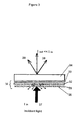
- FIG. 1 shows a known scratch-card structure 1 in which a substrate 10 is provided, typically formed from a paper material such as card.
- the substrate 10 is provided with a layer of an ink 15 providing information to be concealed such as personal identification number (PIN).
- the ink layer 15 is coated with a foil structure having a scratch-off layer 20 typically around 10 micron in thickness.
- the scratch-off layer 20 may be provided by a layer of a latex material.
- the scratch-off layer 20 is in turn coated with a layer of aluminium 30 which is coated with either a layer 40 being a layer of printing ink or a layer of a material having an embossed surface providing a holographic structure.
- the scratch off concealment layer is both secure against counterfeit and highly opaque to prevent unauthorised access to the number by read through methods using high intensity light sources hence holographic ( embossed ) diffractive foil structures are often used.
- the opacity of the holographic scratch off foil is high enough to defeat all known potential forms of number read through using high intensity light sources. It is also important that the foil opacity remains high even under mechanical deformation or bending of the foil.
- a structure comprising: a template layer having a first surface having an optically active surface relief; and an epibarrier layer provided over the first surface of the template layer, the epibarrier layer having an optically active surface relief corresponding substantially to that of the first surface of the template layer, wherein the template layer comprises a plurality of particles arranged to span substantially an entire thickness of the template layer and to provide said optically active surface relief.
- the template layer effectively comprises a monolayer of particles, the monolayer of particles being supported on a substrate on which the template layer is formed.
- the presence of the template layer which 'deplanarises' what would otherwise be a relatively flat surface of the epibarrier layer, reduces a propensity of the epibarrier layer to crack, e.g. when subject to a bending force. This is particularly useful where a barrier layer is formed from a metal oxide material.
- epibarrier layer refers to a layer formed over the template layer.
- the template layer may be formed over a first barrier layer.
- the first and epibarrier layers are preferably each formed from at least one selected from amongst a metal and a metal oxide.
- a metal oxide allows a transparent barrier layer to be formed in the case that a transparent metal oxide is used.
- the first and epibarrier layers are both formed from a transparent metal oxide a transparent structure may be formed.
- the particles are preferably bound to a binder material provided between the particles, the particles optionally comprising at least one selected from amongst a metal and a ceramic material, the ceramic material being optionally aluminium trioxide, titanium dioxide or calcium carbonate and wherein the binder is optionally a soft polymer, preferably an acrylate.
- the particles provide the optically active surface relief of the template layer by protruding from a layer of binder material.
- the binder material is deposited on a substrate such as the first barrier layer in embodiments having the first barrier layer.
- the template layer may be formed in a relatively rapid and simple manner.
- the nature of the optically active surface may be controlled by varying the number and size of particles in a given volume of binder. Thus, a higher concentration of particles in the binder will result in a smaller spacing between particles whilst a lower concentration of particles will result in a larger spacing between particles.
- an average size of the particles may be varied to vary a surface relief of the template layer.
- the template layer is formed to have a weight of around one gramme per square meter. In some embodiments the template layer has a weight of from 0.25 to around 1.5 grammes per square meter. Other weights are also useful.
- the binder layer may have a thickness less than or substantially equal to half an average diameter of the particles.
- the template layer may have a surface relief having a local variation in height from a peak region to a valley region of the surface as viewed in cross-section in the range of from around 0.1 to around 5 microns, preferably around 2 microns, the surface relief further having a lateral spacing between respective adjacent peak regions or respective adjacent valley regions of from around 0.1 to around 5 microns, preferably around 2 microns.
- the average diameter of the particles may be in the range from around 1 micron to around 5 microns, preferably from around 1 micron to around 3.5 microns, more preferably around 2 microns.
- the first barrier layer is preferably formed from a metal and provided with an optically active surface relief, the optically active surface relief having optionally at least one selected from amongst a holographic surface relief, a non-holographic diffractive surface relief and a diffusive surface relief.
- a layer of a scratch-off adhesive is provided over the epibarrier layer whereby the structure may be adhered to an article, the structure being optionally provided on a carrier.
- an ultrahigh opacity holographic scratch-off foil comprising a structure according to the first aspect wherein the optically active surface relief is a holographic surface relief and the first and epibarrier layers are each formed from a metal.
- a substantially gas-impermeable structure comprising a structure according to the first or second aspect of the invention wherein optionally the first barrier layer and the epibarrier layer are formed respectively formed from one selected from amongst metal and metal, metal and metal oxide, metal oxide and metal, and metal oxide and metal oxide, the metal oxide being optionally a transparent metal oxide.
- This structure has the advantage that a barrier layer having increased resistance to cracking and delamination may be formed due to the optically active surface relief of the epibarrier layer and optionally the first barrier layer.
- the use of a transparent metal oxide has the advantage that a transparent structure may be formed.
- a method of forming a structure comprising: forming a template layer having a first surface having an optically active surface relief; and forming an epibarrier layer over the template layer, the epibarrier layer having a first surface having a surface relief corresponding substantially to that of the template layer, wherein the step of forming the template layer comprises depositing a formulation comprising a plurality of particles provided in a binder, the template layer being formed whereby the particles are arranged to span substantially an entire thickness of the template layer and to provide the optically active surface relief.
- the template layer is formed by means of a gravure coating process.
- the method comprises the step of forming the template layer over a first barrier layer, and wherein the first and epibarrier layers are optionally formed from at least one selected from amongst a metal and a metal oxide, the method optionally further comprising the step of embossing the first barrier layer thereby to provide the first barrier layer with an optically active surface relief, preferably a holographic surface relief.
- a method of protecting information comprising the step of bonding a structure according to the first or second aspect to a surface bearing confidential information by means of said scratch-off adhesive.
- Some aspects of the invention relate to two key realisations. Firstly, that the opacity of a scratch off foil or other light barrier can be significantly enhanced by the inclusion of a microstructured metal film with a random optical diffusion or light scattering structure.
- the filler particles are bonded to the substrate by means of a binder layer such as an adhesive layer, the particles being deposited on the substrate typically by depositing a wet composition comprising an adhesive and the particles (the film is formed to be as thin as possible) and then creating an effective diffuser by metallising the structure so that the gravure coating provides a mould for the metal film.
- the film is arranged to bond the filler particles to form a wetting layer over the surface of a substrate.
- a very high efficency diffuser is made possible because a structure may be formed having surface relief features with a relatively high aspect ratio and a relatively small lateral spacing between peaks and valleys of the surface relief as compared with conventional embossing techniques where the surface relief is typically subject to relaxation following embossing, resulting in a reduction in the extent to which the structure diffuses light.
- a structure arranged substantially to prevent passage of light and/or gas therethrough comprising a plurality of barrier layers each barrier layer being a layer of a metallic material or a layer of a metal oxide, wherein at least one of the barrier layers has a micro-structured surface relief arranged to randomly scatter or diffract interferometrically light incident thereon, wherein the plurality of barrier layers are provided in a mutually spaced apart configuration with respect to one another by means of a spacer layer.
- a structure arranged substantially to prevent passage of light and/or gas therethrough comprising a plurality of barrier layers each barrier layer comprising a layer of a metallic material or a layer of a metal oxide, wherein at least one of the barrier layers has a surface relief microstructure having a local variation in height from a peak region to a valley region of the surface as viewed in cross-section in the range of from around 0.1 to around 5 microns, the surface relief microstructure further having a lateral spacing between respective adjacent peak regions or respective adjacent valley regions of from around 0.1 to around 5 microns, the plurality of barrier layers being provided in a mutually spaced apart configuration with respect to one another by means of a spacer layer.
- an optically effective light barrier structure can be provided by forming one of the barrier layers having the surface relief microstructure from a metallic material.
- gas barrier structures not requiring optical opacity metal oxide barrier layers may be used without a requirement to use barrier layers formed from a metallic material.
- transparent and/or translucent metal oxide layers may be used.
- a particularly advantageous embodiment of this is in the form of an advanced high opacity holographic scratch off foil where the bi layer structure offers superior high opacity properties and which provides a retention of the highly opaque properties even under bending deformation designed to crack aluminium layers.
- the diffusing films may be patterned and may be made into directional diffusers to form a new class of lower cost mass manufacturable optically variable devices.
- a particular advantageous embodiment of this is in the form of an advanced high opacity holographic scratch off foil where the bi layer structure offers superior high opacity properties and which provides a retention of the highly opaque properties even under bending deformation designed to crack aluminium layers.
- the metallic fine structure to form an efficient diffuser is then formed by using this spacer layer surface relief as a mould when over metallising by vacuum deposition to replicate the surface relief pattern typically using aluminium or similar.
- An alternative in this invention to form the micro structured spacer layer is to use conventional diffractive embossing, using either a diffractive or random diffusing shim, preferably in one method by using a UV cured embossing system by coating the spacer layer as an uncured embossing lacquer impressing it against a micro-structured embossing shim and curing the lacquer to harden it either via direct UV exposure whilst on shim in situ or immediately after release from the shim before the fine structure pattern has had time to relax.
- One particularly advantageous application is to enhance the opacity of holographic scratch off foils in data protection applications by using the existing metallised holographic layer, generally a metallised holographic or diffractive surface relief, backed by a thin layer of micro-pattern diffusing structure scale thickness less than or equal to 1-1.5 um, forming under the holographic layer a thin diffusing structure which enhances the opacity of the structure by diffusion, aluminium opacity ( reduction of combined pinholes) increases the opacity of the structure under bending by reducing any tendency for the metallised layers to crack.
- the existing metallised holographic layer generally a metallised holographic or diffractive surface relief, backed by a thin layer of micro-pattern diffusing structure scale thickness less than or equal to 1-1.5 um, forming under the holographic layer a thin diffusing structure which enhances the opacity of the structure by diffusion, aluminium opacity ( reduction of combined pinholes) increases the opacity of the structure under bending by
- the micro optic diffusing structure would typically be formed by gravure printing / coating or UV casting of scale size average thickness 1 um or less and average large scale structure spacing typically 35 microns or less with random fine repeated structure of 5 microns or less where this second structure would be metallised to make this both highly diffusing and highly opaque.
- This second layer would then be coated with a conventional heat activated scratch off adhesive / ink to form a conventional holographic scratch off hot stamping foil that could be transferred to a scratch off card under heat and pressure.
- the second metallic layer in a composite structure remains invisible and buried within the composite structure although it remains functionally strongly diffusing and scattering to any incident light upon it, for example in any attempts to try to access PIN numbers via light transmission using high intensity light sources.
- the first metallised layer may be plain or desirably patterned or all over diffusing or diffractively patterned e.g. with a custom hologram;
- the second thin sub micron diffusing spacer layer consists of a clear non light absorbing polymer layer and again ideally adjusted to provide a good adhesion for subsequent metallised layers and containing a micro roughened or 'micro structured' surface relief formed using the contoured surface of the application roller applied by traditional wet gravure coating / printing or alternatively by UV casting a micro structure off an embossing shim as discussed later.
- the final layer consists of a second layer of metallization (usually aluminium , but not restricted to this) which conforms to the spacer layer surface relief to provide a reflective metal coating containing the micro roughened surface relief pattern of the spacer layer - this micro roughened reflective diffuser structure offers superior opacity over previous structures by incorporating a high degree of diffusion into any transmitted light thus decreasing the transmitted light throughput and helping to increase the opacity.
- a second layer of metallization usually aluminium , but not restricted to this
- the spacer layer can also optionally be chosen to have a high retention for incident metal vapour during vacuum coating to increase the metal density applied in a pass and to reduce pinholes. This is particularly useful when applied to say clear barrier coatings for gas barriers such as AIOx.
- a reflective material such as aluminium or other metallic reflector
- the twin reflective surface relief structure is chosen because the additional surface relief micro-structure serves to increase opacity by preferably diffusing or diffracting incident or transmitted light, thus reducing the directly transmitted flux and so increasing the light blocking ability. Additionally pinholes in the film tend to run perpendicular to the film surface so for a structure surface the pinholes do not propagate light in the direction of an observer but serve to diffuse any transmitted light into the interlayer gap where it can undergo multiple internal reflections and be trapped more effectively.
- the surface area is increased very significantly over a planar surface ( say by 20 -35%) such that for any given aluminium film vacuum metallised thickness the actual areal aluminium ( or other opaque metal or non metallic barrier film material) is significantly increased leading to a significantly increased optical density compared to a planar metallised layer so hence the light or gas blocking ability of the metal ( or barrier) layer is be increased.
- aluminium would be used, but other metals could be used and for transparent barrier layer transparent coatings such as AlOx can be used.
- a particularly suitable form of diffusing structure envisaged for use is a new class of micro optic diffusing structure formed by gravure coating and gravure printing from specialist fine patterned rollers using specialist coating formulations designed to maintain their structure when applied to a material, wherein the average thickness of the micro optic diffusing coating lies between 0.2 and 1.2 micron with the optical properties being controlled by both the gravure roller cell geometry and pitch and the chemistry of the coating solution , particularly the filler size of the material (usefully about 2x the average coating thickness to provide some roughness and diffusion and minimise spread of coating liquid before drying).
- the coating solutions contain a wax to promote easy cylinder release, a high solids content to promote fast drying and a high filler content ( typically of a large size of a few microns) again to promote drying and roughen and diffuse the final surface plus a polymer binding agent.
- a typical spacer layer formulation suitable for gravure coating diffuser structure of this pattern and for subsequent use in a scratch off application could consist of a high proportion ( e.g.
- filler to provide the diffusion and softness required with a typical size scale of 0.7 - 3.0 um diameter
- eg Aluminium trioxide particles, titanium dioxide, calcium carbonate or inert fillers such as ceramics mixed with a soft polymer for example formulated from standard polymer heat activated materials, rubbers and waxes - given here as one of many possible methods. It may be appreciated that other formulation types may also be used to achieve the realisation of this aspect of the invention.
- This coating surface can subsequently be metallised - aluminium is a typical coating for light barriers.
- aluminium or clear AIOx or similar can be used.
- the surface character of the coating that makes it soft and easily mouldable also makes it retentive during the metallization process allowing a relatively thick metallised layer to be deposited.
- the resulting surface after metallisation forms an extremely effective 'white effect' metallised diffuser whose diffusion angle effectively depends on the thickness of the coatings and pitch of the coating rollers being used - generally smaller pitched rollers provide finer diffusing and thus white structures, gravure roller pitches typically in the region 300 lines / inch to 1000 lines per inch can be used depending on the structure requirement.
- a particularly advantageous use envisaged for this new micro-diffuser technology is to create new very high opacity scratch off foil structures for the phone-card recharge market where the scratch off foil, be it holographic or printed, is the main data protection device against unauthorised access to the PIN number.
- the scratch off foil has to be proof against various number-reading techniques including optical transmission number access via high intensity light transmission and against bending of the foil in an attempt to crack the foil coatings and enable easier PIN number visualisation by light transmission using intense light sources.
- the same principle can be used to build up a very high opacity scratch label for phonecard POIN protection usage which can be manufactured by either transferring the above scratch off hot stamping foil to a self adhesive label substrate by heat transfer or lamination or by building the structure up in reverse starting by coating the layer (v) on a self adhesive substrate and finishing off by transferring an uncoated holographic or printed foil or by coating and casting a hologram directly into the material.
- This bulk self adhesive scratch off label substrate material would then be die cut and slit to give the scratch off label format suitable for application to phone cards to protect PIN numbers and would be applied on personalisation lines.
- Such structures could also be used to provide high opacity holographic or white printed scratch off labels - in which case the carrier layer above would be absent and the lower scratch off layer would be adhered to a frangible self adhesive substrate layer.
- the scratch off label would be applied over the PIN number and the scratch off foil layer removed by abrasion to reveal the PIN number through the transparent self adhesive label base.
- additional intermediate diffusers can be used (for example a 2, 3 or 4, ... etc metallised diffuser type system) where greater light blocking and flexibility resistance is required for example in potential technical applications for very high efficiency gas barriers e.g. ink reservoirs for inkjet systems and the like.
- the micro roughened diffusing surface could also be manufactured instead using a moulding or casting process probably by moulding a surface relief pattern from an embossing shim into a (typically) UV light curable layer applied to the metal surface - the moulding could then by cured in situ (actually on the moulding roller say by means of using a transparent roller) or cured away from the moulding head.
- This process would thus provide an equivalent structure to the one envisaged using a UV cured moulding technique between the metallised layers by moulding either a random diffuser as per the gravure case or by moulding a diffractive structure as per the UV cured case.
- an alternative secondary method of producing the micro-patterned surface is to take for example a metallised holographic or printed surface, as formed as a hot stamping foil, coat it with a UV curable lacquer and impress into the UV curable lacquer either a micro diffuser or diffractive surface relief structure before curing the UV lacquer in situ or rapidly post embossing.
- micro -roughening of the diffuser type surface relief is not so relevant for barrier coatings such a structure actually has big advantages because it de-planarises the metallic / dielectric layers making them far less susceptible to cracking under bending and also increasing their area density.
- a first metallised or dielectric layer would be applied to a film, for a barrier coating, or a holographic hot stamping foil for a scratch off foil coating.
- the micro roughened diffuser layer (or regular patterned micro layer such as a diffraction grating) would then be applied in vacuum say using an acrylate with a patterned gravure coating or embossing roller, the acrylate would be UV cured, and then the second metal layer or dielectric layer would be applied on the micro roughened surface to provide the structure. If necessary the method could be repeated for lower permeability light barrier or gas barrier coatings. This provides the possibility of using a 2 evaporator metalliser with a suitable intermediate coating and UV curing station to produce the enhanced light barrier or gas barrier coatings in one pass.
- coloured or dark holographic scratch foil can be manufactured.
- the first holographic layer is either partially metallised with Al, to low optical density say 0.2-0.4, the pattern metallised (e.g. by a chemical demetallisation process or spot metallization) or HRI coated with Zinc sulphide for example to give a semi transparent holographic layer.
- the coated spacer layer is run behind this semi-transparent layer, altered to have a high black content or high colour content and then the structure is re-metallised.
- a second spacer layer and second aluminium layer may be added to further increase the opacity to high levels and then a final coating or multiple coatings of scratch off adhesive applied.
- the scratch-off layer is formed to have a free surface having a 'micro-rough' or 'micro-structured' surface topography.
- the surface topography is arranged whereby the layer acts as a diffuser of light that is incident thereon thereby to increase an opacity of the overall layer.
- the scratch-off layer is provided by a layer of a soft material containing particles of a filler material.
- the particles of filler material are arranged to provide the micro-rough surface topography. In some embodiments the particles of filler material have a diameter in the range of from around 0.25 micron to around 2.5 microns.
- the particles are arranged to provide a layer having an RMS (root mean square) surface roughness in the range of from around 0.2 microns to around 4 microns, preferably from around 0.2 micron to around 2.5 microns.
- RMS root mean square
- the scratch-off layer is provided with a first metallic layer thereover, the metallic layer being substantially opaque to visible light. It is to be understood that the surface of the first metallic layer is arranged to conform substantially to the surface topography of the scratch-off layer.
- the first metallic layer is sufficiently thin that a free surface of the first metallic layer following formation of the layer has a similar roughness to the surface of the first metallic layer that is in contact with the scratch-off layer.
- a diffuser layer is provided over the first metallic layer. The surface of the diffuser layer in contact with the first metallic layer conforms substantially to the shape of the first metallic layer, the diffuser layer being arranged to diffuse light incident on that surface.
- a second metallic layer is formed over the diffuser layer, the second metallic layer in turn having a holographic lacquer layer 140 formed thereon.
- the holographic lacquer layer is embossed to form a holographic surface structure that is visible to a user of the scratch-card structure. It is understood that these new scratch off structures differ from previous structures in that (i) the structure is provided with two metallic layers spaced apart from one another, and (ii) one of the metallic layers has a micro-rough surface.
- the diffusing films may be patterned and may be made into directional diffusers to form a new class of lower cost mass manufacturable optically variable devices.
- This invention relates to a new class of micro optic diffusing structures formed by gravure coating and gravure printing from specialist fine patterned rollers using specialist coating formulations designed to maintain their structure when applied to a material, wherein the average thickness of the micro optic diffusing coating lies between 0.2 and 1.3 micron with the optical properties being controlled by both the roller cell geometry and pitch, and the chemistry of the coating solution, particularly the filler size of the material ( usefully about 2 x the average coating thickness to provide some roughness and diffusion and minimise spread of coating liquid before drying.
- these structures are coated by being run at very high speeds and dried very quickly (full temperature on first ovens) to retain the shape of the coating cylinder cells and lines - effectively using this as a moulding tool.
- the coating solutions contains a high solids content to promote fast drying and a high filler content (typical of a large size of a few microns) again to promote drying and roughen and diffuse the final surface plus a polymer binding agent.
- the coating surface can optionally subsequently be metallised - aluminium is a typical coating.
- the surface character of the coating that makes it soft and easily mouldable also makes it retentive to aluminium during the metallization process allowing a relatively thick aluminium layer to be deposited.
- the resulting surface after metallisation can form an effective 'white metallised diffuser' whose diffusion angle effectively depends on the thickness of the coatings and pitch of the coating rollers being used - generally smaller pitched rollers provide finer diffusing and thus white structures, gravure roller pitches typically in the region 300 lines / inch to 1000 lines per inch can be used depending on the structure requirement.
- the printed diffusers can be made self reflective without metallisation by the incorporation of a metallic or reflective filler into the coating solution allowing for example the production directly of spot metallised optically variable structures.
- This is not as optically efficient as direct metallization, which is preferred for high efficiency structures but does provide the capability for spot application of optically variable (OV) metallic structures useful for example on security papers and with security print.
- gravure coating and printed rollers can be patterned - e.g. to form text or security line-work patterns such as guilloche.
- This technique thus provides the opportunity to print down white or coloured text within a coating and then metallise to give a matt white text or artwork pattern on a metallic background with an enhanced reflective diffusion on the text - providing a noticeably differentiated visual effect.
- This effect can be useful in for example customising simple security foils or data protection scratch off foils, where for example a generic diffraction pattern holographic foil can be customised by taking the non metallised foil, over printing by printing some a thin diffusing pattern and then subsequently metallising to provide a holographic pattern plus bright white holographic style micro-print.
- This directionality micro diffuser possibility also offers useful prospects for simple low cost optically variable security image patterning when combined with patterned rollers - this means that different areas can be made to selectively diffuse at different replay or rotation angles according to the rotation angles of the line structure after subsequent metallization - for example to provide a 90 degree image switch on viewing or a rotating pattern on rotation of the device.
- This enables graphic patterns of micro diffusers to be produced that replay with different intensities by reflecting incident light at different angles - thus providing for a low cost method of manufacturing a new low cost optically variable structure.
- a useful sub-set of the technique is to provide optically switching images by splitting two or more images into sets of interlocking pixels or fine lines ( generally too small to see) containing the different image elements - so for example an area whose image switched between two different images on 90 degree rotation would actually consist on a small scale of each of the separate images written into a particular set of interlocking pixels or lines structures where the different pixels relating to different images actually contained in line gravure structures of different or even 90 degree rotated, orientations to provide an image switch or movement or rotation effect which would become apparent after metallization. It can be deduced that many other optically variable or apparent motion effects can also be made using this technique simply by using the micro-mirror structure created from the metallised gravure structures.
- a useful application of such structures is in manufacturing a new form of printed scratch off foil.
- a plain hot stamping foil, or release coated film would be printed with a patterned diffuser, optionally containing optically variable micro-optic structures. This would then be metallised, generally with aluminium, as an opacifying layer. The foil would then be returned for wet coating with suitable soft and frangible heat seal adhesive to provide scratch off characteristics before final slitting.
- the structure thus produced will look completely different to any other form of printed scratch off foil - the image will consist of bright white coloured diffusing areas of 'print' and 'patterns' on a plain metallic background. Additionally the areas of white diffuser will tend to scatter transmitted and reflected light and so increase the opacity of the applied scratch off foil to read through number access and to obscure any indent of numbers from view by direct reflection, which can be useful when scratch foils are applied to very smooth surface plastic cards (e.g. smooth plastic cards such as PVC or PET cards).
- the foil can also be printed with areas of coloured text or graphics to provide coloured diffusing effects.
- This technique can also be used to form a new type of printed scratch off label wherein the holographic scratch off layer is carried on a transparent self adhesive label base to form a self adhesive label structure.
- This structure can be die cut and then slit as known in the labelling art to form a self adhesive label structure carrying a scratch off holographic layer on a transparent base.
- Such labels can be applied in the phone card field over the PIN numbers on phone cards to act as the data protection device wherein the PIN number is revealed by scratching off the layer of printed or holographic scratch off. It is also useful that such labels have a high opacity to prevent number read through using high intensity light sources
- This technique can also be used to customise or to add additional security to holographic scratch off foils used as data protection devices.
- this can be achieved but a good method for this is to take an embossed but non-metallised holographic foil, gravure print a clear or semi clear( tinted) patterned coating of 0.5-1 um thickness and dot or line pitch between 250 and 1000 lines / mm to provide the active structure after subsequent metallisation, generally with aluminium but other metals may be used.
- This active structure produced will then result in certain areas of the design which are unprinted being entirely holographic or diffractive in nature and certain areas of the design which have been overprinted containing no holographic replay (as this is index matched out) but containing a bright white diffusing structure.
- the printed patterned diffusers detailed above can be combined with the use of such diffusers as light barriers for their opacity enhancing properties.
- This combination can produce an improved opacity novel printed or holographic scratch off foil consisting of and with properties as follows taken from part 1 of this invention as above, namely ...
- such structures could also be used to provide high opacity holographic or white printed scratch off labels - in which case the carrier layer above would be absent and the lower scratch off layer would be adhered to a frangible self adhesive substrate layer.
- this technique could be used to directly mould off a gravure press roller micro prism type of structure - typical scale size pitch of say 5-20 microns.
- this aspect of the invention relates to a new class of micro optic structure formed by gravure coating and gravure printing from specialist fine patterned rollers using specialist coating formulations designed to maintain their structure when applied to a material, for a 5-20 microns pitch structure whose depth may need to vary by up to 5 microns for appreciable effects one would consider using an amended coating thickness to suit the structures concerned say with average thickness of the micro optic diffusing coating lies between 2 and 7 microns with the optical properties being controlled by both the roller cell geometry and pitch and the chemistry of the coating solution, particularly the filler size of the material (usefully about 2 x the average coating thickness to provide some roughness and diffusion and minimise spread of coating liquid before drying).
- these structures are coated by being run at very high speeds and dried very quickly (full temperature on first ovens) to retain the shape of the coating cylinder cells and lines - effectively using this as a moulding tool.
- the coating solutions contain a wax to promote easy cylinder release, a high solids content to promote fast drying and a high filler content (typical of a large size of a few microns) again to promote drying and roughen and diffuse the final surface plus a polymer binding agent.
- micro optic structures can usefully be manufactured by diamond machining - an example would include asymmetric triangular structures with directional reflection - patterning and changing of the slope angle or azimuthal rotation angle of the linear structure will provide an optically variable structure that varies in imaged and optical replay on tilting and rotation of the device. This can be used for simple optically variable patterned rollers.
- any of the above diffusing patterns can be useful metallised as optically variable secure authentication structures.
- any of the above the structures can usefully be left unmetallised for use in transmission as controlled direction or controlled angle transmission optical diffusers.
- optical diffusers it is often useful to increase the effectiveness of the device by forming a diffuser on each side of a clear material - this can be done by double passing the material or preferably by coating both sides of a material on one pass in a coating machine.
- the efficiency of a transmissive diffusing structure can also be enhanced by coating the surface of the structure with a high refractive index material such as zinc sulphide or titanium dioxide.
- a high refractive index material such as zinc sulphide or titanium dioxide.
- Such material can usefully be used for controlled view angle and direction diffusers such as in diffusing elements for LCD display screens or televisions.
- a useful form of structure is one in which much of the diffusing structure is random in pitch and variation to prevent moiré patterns with the underlying pixel pattern. This can usefully be achieved when the diffusing structure relies on a random distribution of fine featured filler particles.
- the diffusers would be coated from gravure rollers of a randomised dot pitch pattern or from diamond turned micro optic structures whose periodicity had been randomised to eliminate periodic structures and so eliminate any moiré effects when overlaid on each other or with a periodic pitched display screen.
- roller pitch could be taken to a much finer scale to look at diffractive scale structures such as holograms and diffraction gratings to look to generate commercial quality embossing structures using a gravure coating / casting process effectively as a high volume, relatively low quality holographic embosser.
- the emboss characteristics would rely on the material being liquid when taking the surface relief (to enable the roller pattern to be filled as a casting tool at low pressure), relatively thixotropic to maintain its surface relief structure as it left the roller then being dried extremely quickly to freeze dry the embossed structure into the film. Because this process effectively runs on a liquid casting process followed by solvent drying rather than a heat softening process the materials flow and mould more easily allowing higher run speeds than traditional embossing.
- Useful materials for these lacquers to take up small fine microstructures will be high solids content structures to ensure minimal shrinkage during drying to maintain the diffractive profile (say 45-75% solids), and materials containing waxes to give a release from the roller.
- the lacquer can usefully contain cross linking materials designed to trigger after drying and heat to provide a higher melt temperature, better physical stability and more solvent resistance to the final structure.
- the lacquer can be a 100% solids UV curable lacquer in which case rather than heat or air drying the embossed cast structure would be cured off to a solid immediately after being structurally formed by the embossing coating roller.
- a 3 transfer roller metering system can be used - a gravure roller runs in the coating solution , a rubber transfer roller that may be patterned to transfer only a certain patterned areas further (i.e. a flexo system) is used as an intermediate roller and then a holographically patterned roller is used as the final roller with the coating impressed into the holographic structure by the smooth transfer roller and transferred in turn onto the substrate by the holographic roller.
- This system has an advantage because by choice of holographic roller and patterned rubber transfer roller to be of the same repeat (i.e. diameter) and run off the same geared set then the selectively coated lacquer is automatically deposited in fixed register to the holographic pattern, without any need for separate coating heads or registration maintenance systems between heads.
- This system will work with both solvent dried casting systems and better fidelity UV cured lacquer systems and will allow the avoidance of coating lacquer on what can sometimes be uneven shim joins on holographic material.
- the lateral arrangement of transitions is substantially periodic. In some embodiments the lateral arrangement of transitions is not periodic.
- the peak regions lie substantially within a single plane. In some embodiments the valley regions additionally or instead lie substantially within a single plane.
- the plane may be defined by a surface of the binder B which may be an adhesive or other material as described above.
- the average lateral distance between adjacent transitions from a peak region to a valley region or vice versa lies in the range from 0.2 micron to 10 microns.
- the average lateral distance between adjacent transitions from a peak region to a valley region or vice versa lies in the range from 0.2 micron to 5 microns.
- the average lateral distance between adjacent transitions from a peak region to a valley region or vice versa lies in the range from 0.2 micron to 3.5 microns.
- the surface relief microstructure has a local variation in thickness from a peak to a valley of the surface as viewed in cross-section in the range of around 0.2 to 3.5 microns.
- a peak of the surface relief microstructure is offset from a valley of the surface relief microstructure in a direction normal to a plane substantially parallel to the surface by an amount in the range of from around 0.2 to around 3.5 microns.
- rollers associated with the printing process were arranged to allow particles having a diameter of up to around 2microns to be deposited on the substrate, the particles being provided in a liquid matrix formed from a mixture of soft polymers such as polyurethane polymers, acrylic polymers and latex polymers.
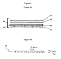
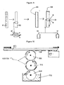
- the spacer layer 520 has a thickness t that typically varies in the range from around t1 between particles (a 'valley region', V) to around t2 where a particle is located (a 'peak region', P). Lateral spacings between particles are typically in the range of from around L1 to around L2.
- t1 is in the range from around 0.2 micron to around 0.7micron, in some embodiments from around 0.3 to around 0.5 micron. In some embodiments t2 is up to around 2 microns, being the maximum diameter particle allowed to pass between rollers associated with the gravure printing process in some embodiments.
- t2 is up to around 3.5 microns.
- the thickness t of the spacer layer varies in the range of from around 0.2 micron to around 3.5 microns as discussed above, preferably around 1 to around 3.5 microns.
- the spacer layer 520 of figure 11 may be coated with a barrier layer formed from a metal, typically aluminium, of a thickness thin enough so that the layer of metal itself has a surface relief pattern on both major surfaces that is similar to that of the spacer layer 520.
- the spacer layer acts as a 'mould' whereby the layer of metal assumes a shape complementary to that of the spacer layer.
- the spacer layer provides a 'former' to shape the layer of metal.
- the metal layer may be considered to be the 'cast' of the spacer layer for this reason.
- the spacer layer 520 may be a transparent metal oxide.
- a transparent metal oxide may be used for the first barrier layer and epi barrier layer in order to enable a transparent structure to be fabricated.
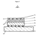
- Figure 12 shows an embodiment in which the spacer layer 520 has been coated with a barrier layer 560 of metal or metal oxide (which may be a transparent metal oxide), the spacer layer having been formed on a further barrier layer 580 which again may be a metal or metal oxide (or combination thereof).
- the metal oxide may be a transparent metal oxide.
- the further barrier layer 580 may also be provided with an optically active surface relief.
- the surface relief of the further barrier layer 580 may be a holographic surface relief formed for example by embossing a metal layer.
- the further barrier layer 580 may itself by formed on a carrier such as a plastics film (e.g. PET) with optionally a release layer between the carrier and the further barrier layer 580.
- a carrier such as a plastics film (e.g. PET) with optionally a release layer between the carrier and the further barrier layer 580.
- a layer of scratch-off adhesive may be provided over the barrier layer 560 for attachment of the structure of figure 12 to a substrate such as a card (e.g. a scratch-card) thereby to protect confidential information from view until the structure is removed from the substrate by a scratching or generally scraping action.
- a substrate such as a card (e.g. a scratch-card)
- the structure of figure 12 is used as a substantially gas impermeable membrane for coating a substrate such as a foil for use in packaging (e.g. food packaging, electronics packaging, etc).
- holographic structure is included reference to a structure arranged to provide a holographic or diffractive image by a process of optical diffraction when illuminated and viewed by a person.
- Embodiments of the invention may also be understood with reference to the following numbered paragraphs.
Landscapes
- Physics & Mathematics (AREA)
- General Physics & Mathematics (AREA)
- Optics & Photonics (AREA)
- Engineering & Computer Science (AREA)
- Mechanical Engineering (AREA)
- Holo Graphy (AREA)
- Credit Cards Or The Like (AREA)
- Laminated Bodies (AREA)
Applications Claiming Priority (3)
| Application Number | Priority Date | Filing Date | Title |
|---|---|---|---|
| GBGB0800716.3A GB0800716D0 (en) | 2008-01-16 | 2008-01-16 | Novel diffusers, novel methods of manufacture, and novel gas and light barrier structures and applications |
| GB0817180.3A GB2456612B (en) | 2008-01-16 | 2008-09-19 | Optical structure |
| GB0817179.5A GB2456611B (en) | 2008-01-16 | 2008-09-19 | Barrier structure |
Publications (3)
| Publication Number | Publication Date |
|---|---|
| EP2081058A2 true EP2081058A2 (de) | 2009-07-22 |
| EP2081058A3 EP2081058A3 (de) | 2012-12-05 |
| EP2081058B1 EP2081058B1 (de) | 2019-08-21 |
Family
ID=39144976
Family Applications (1)
| Application Number | Title | Priority Date | Filing Date |
|---|---|---|---|
| EP09150663.4A Active EP2081058B1 (de) | 2008-01-16 | 2009-01-15 | Sperrstruktur mit Oberflächenrelief |
Country Status (3)
| Country | Link |
|---|---|
| EP (1) | EP2081058B1 (de) |
| GB (3) | GB0800716D0 (de) |
| ZA (1) | ZA200808426B (de) |
Cited By (1)
| Publication number | Priority date | Publication date | Assignee | Title |
|---|---|---|---|---|
| US9308763B2 (en) | 2012-07-09 | 2016-04-12 | Hewlett-Packard Development Company, L.P. | Recording material |
Families Citing this family (1)
| Publication number | Priority date | Publication date | Assignee | Title |
|---|---|---|---|---|
| EP2724864B1 (de) | 2012-10-24 | 2018-12-26 | Heidelberger Druckmaschinen AG | Verfahren und Vorrichtung zur Erzeugung und Übertragung diffraktiver Mikrostrukturen auf einen Bedruckstoff |
Citations (9)
| Publication number | Priority date | Publication date | Assignee | Title |
|---|---|---|---|---|
| DE1572939A1 (de) * | 1966-12-27 | 1970-03-26 | Rank Xerox Ltd | Blattgebilde mit einer informationstragenden Oberflaeche und Verfahren zu dessen Herstellung |
| EP0466118A2 (de) * | 1990-07-10 | 1992-01-15 | GAO Gesellschaft für Automation und Organisation mbH | Mehrschichtiges optisch variables Element |
| US5215576A (en) * | 1991-07-24 | 1993-06-01 | Gtech Corporation | Water based scratch-off ink for gaming forms |
| EP0688838A1 (de) * | 1994-05-10 | 1995-12-27 | Sicpa Holding S.A. | Zusammensetzung für abreibbare Beschichtungen |
| EP1132786A2 (de) * | 2000-03-06 | 2001-09-12 | Illinois Tool Works Inc. | Holographisches Element und Verfahren zum Transferieren von mehreren holographischen Bildern von einem Polymerträger auf einen Papierträger oder gewebeartigen Träger |
| WO2003070483A1 (en) * | 2002-02-19 | 2003-08-28 | 3M Innovative Properties Company | Security laminate |
| DE10326644A1 (de) * | 2003-06-11 | 2005-01-13 | Bundesdruckerei Gmbh | Wertdokument mit einem Sicherheitselement und Verfahren zur Herstellung des Wertdokuments |
| JP2005144878A (ja) * | 2003-11-17 | 2005-06-09 | Toppan Printing Co Ltd | バルーン用積層フィルムおよびバルーン |
| US20070089831A1 (en) * | 2005-10-17 | 2007-04-26 | Celerino Florentino | Card with hologram formed over magnetic strip |
Family Cites Families (10)
| Publication number | Priority date | Publication date | Assignee | Title |
|---|---|---|---|---|
| GB2181993A (en) * | 1985-10-31 | 1987-05-07 | Bpcc Holographic Security Syst | Method and means for preventing counterfeiting of documents |
| JP2921084B2 (ja) * | 1990-10-04 | 1999-07-19 | 凸版印刷株式会社 | 放電破壊記録媒体 |
| DE4212290C2 (de) * | 1992-02-29 | 1996-08-01 | Kurz Leonhard Fa | Wertdokument |
| US5902436A (en) * | 1996-07-09 | 1999-05-11 | Hampshire Holographic Manufacturing Corp. | Method for transferring a metallized holographic image |
| US5723203A (en) * | 1996-07-09 | 1998-03-03 | Stepanek; Stephen B. | Holographically transferable images |
| US5946781A (en) * | 1997-05-09 | 1999-09-07 | Kuo; Weiwu A. | Multi-layer packaging foil and method for manufacturing the foil |
| US6677029B2 (en) * | 1999-12-20 | 2004-01-13 | Applied Extrusion Technologies, Inc. | Holographic films |
| AT502319B1 (de) * | 2002-04-11 | 2009-11-15 | Hueck Folien Gmbh | Substrate mit vorzugsweise transferierbaren schichten und/oder oberflächenstrukturen, verfahren zu deren herstellung und deren verwendung |
| US20050196604A1 (en) * | 2004-03-05 | 2005-09-08 | Unifoil Corporation | Metallization process and product produced thereby |
| JP2008155441A (ja) * | 2006-12-22 | 2008-07-10 | Dainippon Printing Co Ltd | インモールド用転写箔、及びそれを用いた成形品 |
-
2008
- 2008-01-16 GB GBGB0800716.3A patent/GB0800716D0/en not_active Ceased
- 2008-09-19 GB GB0817180.3A patent/GB2456612B/en not_active Expired - Fee Related
- 2008-09-19 GB GB0817179.5A patent/GB2456611B/en not_active Expired - Fee Related
- 2008-10-02 ZA ZA200808426A patent/ZA200808426B/en unknown
-
2009
- 2009-01-15 EP EP09150663.4A patent/EP2081058B1/de active Active
Patent Citations (9)
| Publication number | Priority date | Publication date | Assignee | Title |
|---|---|---|---|---|
| DE1572939A1 (de) * | 1966-12-27 | 1970-03-26 | Rank Xerox Ltd | Blattgebilde mit einer informationstragenden Oberflaeche und Verfahren zu dessen Herstellung |
| EP0466118A2 (de) * | 1990-07-10 | 1992-01-15 | GAO Gesellschaft für Automation und Organisation mbH | Mehrschichtiges optisch variables Element |
| US5215576A (en) * | 1991-07-24 | 1993-06-01 | Gtech Corporation | Water based scratch-off ink for gaming forms |
| EP0688838A1 (de) * | 1994-05-10 | 1995-12-27 | Sicpa Holding S.A. | Zusammensetzung für abreibbare Beschichtungen |
| EP1132786A2 (de) * | 2000-03-06 | 2001-09-12 | Illinois Tool Works Inc. | Holographisches Element und Verfahren zum Transferieren von mehreren holographischen Bildern von einem Polymerträger auf einen Papierträger oder gewebeartigen Träger |
| WO2003070483A1 (en) * | 2002-02-19 | 2003-08-28 | 3M Innovative Properties Company | Security laminate |
| DE10326644A1 (de) * | 2003-06-11 | 2005-01-13 | Bundesdruckerei Gmbh | Wertdokument mit einem Sicherheitselement und Verfahren zur Herstellung des Wertdokuments |
| JP2005144878A (ja) * | 2003-11-17 | 2005-06-09 | Toppan Printing Co Ltd | バルーン用積層フィルムおよびバルーン |
| US20070089831A1 (en) * | 2005-10-17 | 2007-04-26 | Celerino Florentino | Card with hologram formed over magnetic strip |
Cited By (1)
| Publication number | Priority date | Publication date | Assignee | Title |
|---|---|---|---|---|
| US9308763B2 (en) | 2012-07-09 | 2016-04-12 | Hewlett-Packard Development Company, L.P. | Recording material |
Also Published As
| Publication number | Publication date |
|---|---|
| GB2456612B (en) | 2013-02-13 |
| GB2456612A (en) | 2009-07-22 |
| ZA200808426B (en) | 2010-04-28 |
| GB2456611B (en) | 2012-12-26 |
| GB0817179D0 (en) | 2008-10-29 |
| EP2081058B1 (de) | 2019-08-21 |
| GB0800716D0 (en) | 2008-02-20 |
| EP2081058A3 (de) | 2012-12-05 |
| GB2456611A (en) | 2009-07-22 |
| GB0817180D0 (en) | 2008-10-29 |
Similar Documents
| Publication | Publication Date | Title |
|---|---|---|
| US10112432B2 (en) | Security device | |
| CN108603955B (zh) | 防伪用光学元件以及信息记录介质 | |
| AU2008313546B2 (en) | Photonic crystal security device and method | |
| JP5477046B2 (ja) | 表示体及びその製造方法 | |
| RU2435675C2 (ru) | Многослойная подложка с микрооптическим средством | |
| US9731539B2 (en) | Security devices | |
| US8927072B2 (en) | Photonic crystal security device | |
| AU2007293247B2 (en) | Security articles and devices containing coded holographic platelets and methods of manufacturing the same | |
| JP6677165B2 (ja) | 偽造防止用の光学素子 | |
| EP2359196B1 (de) | Sicherheitseinrichtung, Verfahren und Artikel | |
| AU2014210899A1 (en) | Security devices and methods of manufacture thereof | |
| JP2009134094A (ja) | 回折構造転写箔及びそれを用いた偽造防止媒体 | |
| JP4391102B2 (ja) | 真偽判定体 | |
| EP2081058B1 (de) | Sperrstruktur mit Oberflächenrelief | |
| JP4280122B2 (ja) | 装飾シートおよびその製造方法 | |
| JP2005035115A (ja) | 真偽判定体 | |
| JP2004209940A (ja) | 真偽判定体用転写箔と真偽判定体付き認証媒体 | |
| JP2020184036A (ja) | ホログラム一体型印刷物 |
Legal Events
| Date | Code | Title | Description |
|---|---|---|---|
| PUAI | Public reference made under article 153(3) epc to a published international application that has entered the european phase |
Free format text: ORIGINAL CODE: 0009012 |
|
| AK | Designated contracting states |
Kind code of ref document: A2 Designated state(s): AT BE BG CH CY CZ DE DK EE ES FI FR GB GR HR HU IE IS IT LI LT LU LV MC MK MT NL NO PL PT RO SE SI SK TR |
|
| AX | Request for extension of the european patent |
Extension state: AL BA RS |
|
| PUAL | Search report despatched |
Free format text: ORIGINAL CODE: 0009013 |
|
| AK | Designated contracting states |
Kind code of ref document: A3 Designated state(s): AT BE BG CH CY CZ DE DK EE ES FI FR GB GR HR HU IE IS IT LI LT LU LV MC MK MT NL NO PL PT RO SE SI SK TR |
|
| AX | Request for extension of the european patent |
Extension state: AL BA RS |
|
| RIC1 | Information provided on ipc code assigned before grant |
Ipc: G02B 5/02 20060101AFI20121031BHEP Ipc: B44F 1/06 20060101ALI20121031BHEP Ipc: B42D 15/02 20060101ALI20121031BHEP |
|
| 17P | Request for examination filed |
Effective date: 20130605 |
|
| RBV | Designated contracting states (corrected) |
Designated state(s): AT BE BG CH CY CZ DE DK EE ES FI FR GB GR HR HU IE IS IT LI LT LU LV MC MK MT NL NO PL PT RO SE SI SK TR |
|
| AKX | Designation fees paid |
Designated state(s): AT BE BG CH CY CZ DE DK EE ES FI FR GB GR HR HU IE IS IT LI LT LU LV MC MK MT NL NO PL PT RO SE SI SK TR |
|
| GRAP | Despatch of communication of intention to grant a patent |
Free format text: ORIGINAL CODE: EPIDOSNIGR1 |
|
| STAA | Information on the status of an ep patent application or granted ep patent |
Free format text: STATUS: GRANT OF PATENT IS INTENDED |
|
| INTG | Intention to grant announced |
Effective date: 20180508 |
|
| GRAJ | Information related to disapproval of communication of intention to grant by the applicant or resumption of examination proceedings by the epo deleted |
Free format text: ORIGINAL CODE: EPIDOSDIGR1 |
|
| STAA | Information on the status of an ep patent application or granted ep patent |
Free format text: STATUS: REQUEST FOR EXAMINATION WAS MADE |
|
| INTC | Intention to grant announced (deleted) | ||
| GRAP | Despatch of communication of intention to grant a patent |
Free format text: ORIGINAL CODE: EPIDOSNIGR1 |
|
| STAA | Information on the status of an ep patent application or granted ep patent |
Free format text: STATUS: GRANT OF PATENT IS INTENDED |
|
| INTG | Intention to grant announced |
Effective date: 20190228 |
|
| GRAS | Grant fee paid |
Free format text: ORIGINAL CODE: EPIDOSNIGR3 |
|
| GRAA | (expected) grant |
Free format text: ORIGINAL CODE: 0009210 |
|
| STAA | Information on the status of an ep patent application or granted ep patent |
Free format text: STATUS: THE PATENT HAS BEEN GRANTED |
|
| RBV | Designated contracting states (corrected) |
Designated state(s): AT BE BG CH CY CZ DE DK EE ES FI FR GR HR HU IE IS IT LI LT LU LV MC MK MT NL NO PL PT RO SE SI SK TR |
|
| AK | Designated contracting states |
Kind code of ref document: B1 Designated state(s): AT BE BG CH CY CZ DE DK EE ES FI FR GR HR HU IE IS IT LI LT LU LV MC MK MT NL NO PL PT RO SE SI SK TR |
|
| REG | Reference to a national code |
Ref country code: CH Ref legal event code: EP |
|
| REG | Reference to a national code |
Ref country code: DE Ref legal event code: R096 Ref document number: 602009059524 Country of ref document: DE |
|
| REG | Reference to a national code |
Ref country code: AT Ref legal event code: REF Ref document number: 1170395 Country of ref document: AT Kind code of ref document: T Effective date: 20190915 |
|
| REG | Reference to a national code |
Ref country code: IE Ref legal event code: FG4D |
|
| REG | Reference to a national code |
Ref country code: LT Ref legal event code: MG4D |
|
| REG | Reference to a national code |
Ref country code: NL Ref legal event code: MP Effective date: 20190821 |
|
| PG25 | Lapsed in a contracting state [announced via postgrant information from national office to epo] |
Ref country code: NO Free format text: LAPSE BECAUSE OF FAILURE TO SUBMIT A TRANSLATION OF THE DESCRIPTION OR TO PAY THE FEE WITHIN THE PRESCRIBED TIME-LIMIT Effective date: 20191121 Ref country code: HR Free format text: LAPSE BECAUSE OF FAILURE TO SUBMIT A TRANSLATION OF THE DESCRIPTION OR TO PAY THE FEE WITHIN THE PRESCRIBED TIME-LIMIT Effective date: 20190821 Ref country code: PT Free format text: LAPSE BECAUSE OF FAILURE TO SUBMIT A TRANSLATION OF THE DESCRIPTION OR TO PAY THE FEE WITHIN THE PRESCRIBED TIME-LIMIT Effective date: 20191223 Ref country code: LT Free format text: LAPSE BECAUSE OF FAILURE TO SUBMIT A TRANSLATION OF THE DESCRIPTION OR TO PAY THE FEE WITHIN THE PRESCRIBED TIME-LIMIT Effective date: 20190821 Ref country code: BG Free format text: LAPSE BECAUSE OF FAILURE TO SUBMIT A TRANSLATION OF THE DESCRIPTION OR TO PAY THE FEE WITHIN THE PRESCRIBED TIME-LIMIT Effective date: 20191121 Ref country code: NL Free format text: LAPSE BECAUSE OF FAILURE TO SUBMIT A TRANSLATION OF THE DESCRIPTION OR TO PAY THE FEE WITHIN THE PRESCRIBED TIME-LIMIT Effective date: 20190821 Ref country code: FI Free format text: LAPSE BECAUSE OF FAILURE TO SUBMIT A TRANSLATION OF THE DESCRIPTION OR TO PAY THE FEE WITHIN THE PRESCRIBED TIME-LIMIT Effective date: 20190821 Ref country code: SE Free format text: LAPSE BECAUSE OF FAILURE TO SUBMIT A TRANSLATION OF THE DESCRIPTION OR TO PAY THE FEE WITHIN THE PRESCRIBED TIME-LIMIT Effective date: 20190821 |
|
| PG25 | Lapsed in a contracting state [announced via postgrant information from national office to epo] |
Ref country code: GR Free format text: LAPSE BECAUSE OF FAILURE TO SUBMIT A TRANSLATION OF THE DESCRIPTION OR TO PAY THE FEE WITHIN THE PRESCRIBED TIME-LIMIT Effective date: 20191122 Ref country code: ES Free format text: LAPSE BECAUSE OF FAILURE TO SUBMIT A TRANSLATION OF THE DESCRIPTION OR TO PAY THE FEE WITHIN THE PRESCRIBED TIME-LIMIT Effective date: 20190821 Ref country code: IS Free format text: LAPSE BECAUSE OF FAILURE TO SUBMIT A TRANSLATION OF THE DESCRIPTION OR TO PAY THE FEE WITHIN THE PRESCRIBED TIME-LIMIT Effective date: 20191221 Ref country code: LV Free format text: LAPSE BECAUSE OF FAILURE TO SUBMIT A TRANSLATION OF THE DESCRIPTION OR TO PAY THE FEE WITHIN THE PRESCRIBED TIME-LIMIT Effective date: 20190821 |
|
| REG | Reference to a national code |
Ref country code: AT Ref legal event code: MK05 Ref document number: 1170395 Country of ref document: AT Kind code of ref document: T Effective date: 20190821 |
|
| PG25 | Lapsed in a contracting state [announced via postgrant information from national office to epo] |
Ref country code: TR Free format text: LAPSE BECAUSE OF FAILURE TO SUBMIT A TRANSLATION OF THE DESCRIPTION OR TO PAY THE FEE WITHIN THE PRESCRIBED TIME-LIMIT Effective date: 20190821 |
|
| PG25 | Lapsed in a contracting state [announced via postgrant information from national office to epo] |
Ref country code: IT Free format text: LAPSE BECAUSE OF FAILURE TO SUBMIT A TRANSLATION OF THE DESCRIPTION OR TO PAY THE FEE WITHIN THE PRESCRIBED TIME-LIMIT Effective date: 20190821 Ref country code: AT Free format text: LAPSE BECAUSE OF FAILURE TO SUBMIT A TRANSLATION OF THE DESCRIPTION OR TO PAY THE FEE WITHIN THE PRESCRIBED TIME-LIMIT Effective date: 20190821 Ref country code: DK Free format text: LAPSE BECAUSE OF FAILURE TO SUBMIT A TRANSLATION OF THE DESCRIPTION OR TO PAY THE FEE WITHIN THE PRESCRIBED TIME-LIMIT Effective date: 20190821 Ref country code: EE Free format text: LAPSE BECAUSE OF FAILURE TO SUBMIT A TRANSLATION OF THE DESCRIPTION OR TO PAY THE FEE WITHIN THE PRESCRIBED TIME-LIMIT Effective date: 20190821 Ref country code: RO Free format text: LAPSE BECAUSE OF FAILURE TO SUBMIT A TRANSLATION OF THE DESCRIPTION OR TO PAY THE FEE WITHIN THE PRESCRIBED TIME-LIMIT Effective date: 20190821 Ref country code: PL Free format text: LAPSE BECAUSE OF FAILURE TO SUBMIT A TRANSLATION OF THE DESCRIPTION OR TO PAY THE FEE WITHIN THE PRESCRIBED TIME-LIMIT Effective date: 20190821 |
|
| PG25 | Lapsed in a contracting state [announced via postgrant information from national office to epo] |
Ref country code: IS Free format text: LAPSE BECAUSE OF FAILURE TO SUBMIT A TRANSLATION OF THE DESCRIPTION OR TO PAY THE FEE WITHIN THE PRESCRIBED TIME-LIMIT Effective date: 20200224 Ref country code: SK Free format text: LAPSE BECAUSE OF FAILURE TO SUBMIT A TRANSLATION OF THE DESCRIPTION OR TO PAY THE FEE WITHIN THE PRESCRIBED TIME-LIMIT Effective date: 20190821 Ref country code: CZ Free format text: LAPSE BECAUSE OF FAILURE TO SUBMIT A TRANSLATION OF THE DESCRIPTION OR TO PAY THE FEE WITHIN THE PRESCRIBED TIME-LIMIT Effective date: 20190821 |
|
| REG | Reference to a national code |
Ref country code: DE Ref legal event code: R097 Ref document number: 602009059524 Country of ref document: DE |
|
| PLBE | No opposition filed within time limit |
Free format text: ORIGINAL CODE: 0009261 |
|
| STAA | Information on the status of an ep patent application or granted ep patent |
Free format text: STATUS: NO OPPOSITION FILED WITHIN TIME LIMIT |
|
| PG2D | Information on lapse in contracting state deleted |
Ref country code: IS |
|
| 26N | No opposition filed |
Effective date: 20200603 |
|
| PG25 | Lapsed in a contracting state [announced via postgrant information from national office to epo] |
Ref country code: SI Free format text: LAPSE BECAUSE OF FAILURE TO SUBMIT A TRANSLATION OF THE DESCRIPTION OR TO PAY THE FEE WITHIN THE PRESCRIBED TIME-LIMIT Effective date: 20190821 Ref country code: MC Free format text: LAPSE BECAUSE OF FAILURE TO SUBMIT A TRANSLATION OF THE DESCRIPTION OR TO PAY THE FEE WITHIN THE PRESCRIBED TIME-LIMIT Effective date: 20190821 |
|
| REG | Reference to a national code |
Ref country code: CH Ref legal event code: PL |
|
| REG | Reference to a national code |
Ref country code: BE Ref legal event code: MM Effective date: 20200131 |
|
| PG25 | Lapsed in a contracting state [announced via postgrant information from national office to epo] |
Ref country code: LU Free format text: LAPSE BECAUSE OF NON-PAYMENT OF DUE FEES Effective date: 20200115 Ref country code: FR Free format text: LAPSE BECAUSE OF NON-PAYMENT OF DUE FEES Effective date: 20200131 |
|
| PG25 | Lapsed in a contracting state [announced via postgrant information from national office to epo] |
Ref country code: LI Free format text: LAPSE BECAUSE OF NON-PAYMENT OF DUE FEES Effective date: 20200131 Ref country code: CH Free format text: LAPSE BECAUSE OF NON-PAYMENT OF DUE FEES Effective date: 20200131 Ref country code: BE Free format text: LAPSE BECAUSE OF NON-PAYMENT OF DUE FEES Effective date: 20200131 |
|
| PG25 | Lapsed in a contracting state [announced via postgrant information from national office to epo] |
Ref country code: IE Free format text: LAPSE BECAUSE OF NON-PAYMENT OF DUE FEES Effective date: 20200115 |
|
| PGFP | Annual fee paid to national office [announced via postgrant information from national office to epo] |
Ref country code: DE Payment date: 20210129 Year of fee payment: 13 |
|
| PG25 | Lapsed in a contracting state [announced via postgrant information from national office to epo] |
Ref country code: MT Free format text: LAPSE BECAUSE OF FAILURE TO SUBMIT A TRANSLATION OF THE DESCRIPTION OR TO PAY THE FEE WITHIN THE PRESCRIBED TIME-LIMIT Effective date: 20190821 Ref country code: CY Free format text: LAPSE BECAUSE OF FAILURE TO SUBMIT A TRANSLATION OF THE DESCRIPTION OR TO PAY THE FEE WITHIN THE PRESCRIBED TIME-LIMIT Effective date: 20190821 |
|
| PG25 | Lapsed in a contracting state [announced via postgrant information from national office to epo] |
Ref country code: MK Free format text: LAPSE BECAUSE OF FAILURE TO SUBMIT A TRANSLATION OF THE DESCRIPTION OR TO PAY THE FEE WITHIN THE PRESCRIBED TIME-LIMIT Effective date: 20190821 |
|
| REG | Reference to a national code |
Ref country code: DE Ref legal event code: R119 Ref document number: 602009059524 Country of ref document: DE |
|
| PG25 | Lapsed in a contracting state [announced via postgrant information from national office to epo] |
Ref country code: DE Free format text: LAPSE BECAUSE OF NON-PAYMENT OF DUE FEES Effective date: 20220802 |