EP2080424B1 - Device and method for producing microwave plasma with a high plasma density - Google Patents
Device and method for producing microwave plasma with a high plasma density Download PDFInfo
- Publication number
- EP2080424B1 EP2080424B1 EP07818910A EP07818910A EP2080424B1 EP 2080424 B1 EP2080424 B1 EP 2080424B1 EP 07818910 A EP07818910 A EP 07818910A EP 07818910 A EP07818910 A EP 07818910A EP 2080424 B1 EP2080424 B1 EP 2080424B1
- Authority
- EP
- European Patent Office
- Prior art keywords
- dielectric tube
- gas
- microwave
- fluid
- outer dielectric
- Prior art date
- Legal status (The legal status is an assumption and is not a legal conclusion. Google has not performed a legal analysis and makes no representation as to the accuracy of the status listed.)
- Not-in-force
Links
Images


Classifications
-
- H—ELECTRICITY
- H05—ELECTRIC TECHNIQUES NOT OTHERWISE PROVIDED FOR
- H05H—PLASMA TECHNIQUE; PRODUCTION OF ACCELERATED ELECTRICALLY-CHARGED PARTICLES OR OF NEUTRONS; PRODUCTION OR ACCELERATION OF NEUTRAL MOLECULAR OR ATOMIC BEAMS
- H05H1/00—Generating plasma; Handling plasma
- H05H1/24—Generating plasma
- H05H1/46—Generating plasma using applied electromagnetic fields, e.g. high frequency or microwave energy
-
- H—ELECTRICITY
- H01—ELECTRIC ELEMENTS
- H01J—ELECTRIC DISCHARGE TUBES OR DISCHARGE LAMPS
- H01J37/00—Discharge tubes with provision for introducing objects or material to be exposed to the discharge, e.g. for the purpose of examination or processing thereof
- H01J37/32—Gas-filled discharge tubes
- H01J37/32009—Arrangements for generation of plasma specially adapted for examination or treatment of objects, e.g. plasma sources
- H01J37/32192—Microwave generated discharge
-
- H—ELECTRICITY
- H01—ELECTRIC ELEMENTS
- H01J—ELECTRIC DISCHARGE TUBES OR DISCHARGE LAMPS
- H01J37/00—Discharge tubes with provision for introducing objects or material to be exposed to the discharge, e.g. for the purpose of examination or processing thereof
- H01J37/32—Gas-filled discharge tubes
- H01J37/32009—Arrangements for generation of plasma specially adapted for examination or treatment of objects, e.g. plasma sources
- H01J37/32366—Localised processing
-
- H—ELECTRICITY
- H01—ELECTRIC ELEMENTS
- H01J—ELECTRIC DISCHARGE TUBES OR DISCHARGE LAMPS
- H01J37/00—Discharge tubes with provision for introducing objects or material to be exposed to the discharge, e.g. for the purpose of examination or processing thereof
- H01J37/32—Gas-filled discharge tubes
- H01J37/32431—Constructional details of the reactor
- H01J37/32458—Vessel
- H01J37/32522—Temperature
-
- H—ELECTRICITY
- H01—ELECTRIC ELEMENTS
- H01J—ELECTRIC DISCHARGE TUBES OR DISCHARGE LAMPS
- H01J37/00—Discharge tubes with provision for introducing objects or material to be exposed to the discharge, e.g. for the purpose of examination or processing thereof
- H01J37/32—Gas-filled discharge tubes
- H01J37/32431—Constructional details of the reactor
- H01J37/32733—Means for moving the material to be treated
- H01J37/32752—Means for moving the material to be treated for moving the material across the discharge
- H01J37/32761—Continuous moving
- H01J37/3277—Continuous moving of continuous material
-
- H—ELECTRICITY
- H05—ELECTRIC TECHNIQUES NOT OTHERWISE PROVIDED FOR
- H05H—PLASMA TECHNIQUE; PRODUCTION OF ACCELERATED ELECTRICALLY-CHARGED PARTICLES OR OF NEUTRONS; PRODUCTION OR ACCELERATION OF NEUTRAL MOLECULAR OR ATOMIC BEAMS
- H05H1/00—Generating plasma; Handling plasma
- H05H1/24—Generating plasma
- H05H1/46—Generating plasma using applied electromagnetic fields, e.g. high frequency or microwave energy
- H05H1/461—Microwave discharges
- H05H1/463—Microwave discharges using antennas or applicators
-
- H—ELECTRICITY
- H05—ELECTRIC TECHNIQUES NOT OTHERWISE PROVIDED FOR
- H05H—PLASMA TECHNIQUE; PRODUCTION OF ACCELERATED ELECTRICALLY-CHARGED PARTICLES OR OF NEUTRONS; PRODUCTION OR ACCELERATION OF NEUTRAL MOLECULAR OR ATOMIC BEAMS
- H05H1/00—Generating plasma; Handling plasma
- H05H1/24—Generating plasma
- H05H1/2406—Generating plasma using dielectric barrier discharges, i.e. with a dielectric interposed between the electrodes
- H05H1/2443—Generating plasma using dielectric barrier discharges, i.e. with a dielectric interposed between the electrodes the plasma fluid flowing through a dielectric tube
- H05H1/245—Generating plasma using dielectric barrier discharges, i.e. with a dielectric interposed between the electrodes the plasma fluid flowing through a dielectric tube the plasma being activated using internal electrodes
Definitions
- the invention relates to a device for generating high plasma density microwave plasmas, which has at least one microwave feed, which is surrounded by at least one dielectric tube. Furthermore, a method of generating high plasma density microwave plasma by use of this device will be described.
- Devices for generating microwave plasmas are used in the plasma treatment of workpieces and gases.
- the plasma treatment is used for.
- As the coating, cleaning, modification and etching of workpieces for the treatment of medical implants, for textile treatment, for sterilization, for light generation, preferably in the spectral range infrared to ultraviolet, for the implementation of gases or for gas synthesis and in the art for exhaust gas purification.
- the workpiece or gas to be treated is brought into contact with the plasma or the microwave radiation.
- the geometry of the workpieces to be treated ranges from flat substrates, fibers and webs to moldings of any shape.
- the most important process gases are noble gases, fluorine- and chlorine-containing gases, hydrocarbons, furans, dioxins, hydrogen sulfide, oxygen, hydrogen, nitrogen, tetrafluoromethane, sulfur hexafluoride, air, water and their mixtures.
- the exhaust gas cleaning by microwave induced Plasma consists of the process gas from exhaust gases of all kinds, in particular carbon monoxide, hydrocarbons, nitrogen oxides, aldehydes and sulfur oxides.
- these gases can readily be used as process gases for other applications.
- the above-mentioned documents have in common that they describe a microwave antenna inside a dielectric tube. If microwaves are generated in the interior of such a tube, surface waves form along the outside thereof. These surface waves generate a linearly stretched plasma in a process gas which is under low pressure. Typical lower pressures are 0.1 mbar - 10 mbar.
- the volume inside the dielectric tube is typically at ambient pressure (generally normal pressure, about 1013 mbar).
- a cooling gas flow through the tube is used to cool the dielectric tube.
- microwaves for the supply of microwaves, inter alia, waveguide and coaxial, as coupling points in the wall of the plasma chamber, inter alia, antennas and slots are used.
- Such leads for microwaves and coupling points are, for example, in DE 423 59 14 and WO 98/59359 A1 described.
- the microwave frequencies used to generate the plasma are preferably in the range of 800 MHz to 2.5 GHz, more preferably in the ranges of 800 MHz to 950 MHz and 2.0-2.5 GHz, but the microwave frequency can be in the entire range of 10 MHz to some 100 GHz.
- DE 198 480 22 A1 and DE 195 032 05 C1 describe devices for generating plasma in a vacuum chamber by means of electromagnetic alternating fields, with a conductor which projects within a tube of insulating material in the vacuum chamber, wherein the insulating tube at both ends by walls of the vacuum chamber and sealed against the walls on its outer surface is.
- the ends of the conductor are connected to a generator for generating the electromagnetic alternating fields.
- these sources are typically operated with microwave power of about 1 - 2 kW at a correspondingly low pressure (about 0.1 - 0.5 mbar).
- the process pressures can Although also 1 mbar - 100 mbar be, but only under certain conditions and correspondingly lower power, so as not to destroy the pipe.
- the object of the present invention is to overcome the abovementioned disadvantages and thus to obtain an increase in the plasma concentration and the process gas pressure.
- a device for producing microwave plasmas according to claim 1.
- This device has at least one microwave feed, which is surrounded by an inner dielectric tube.
- This inner dielectric tube is in turn surrounded by at least one outer dielectric tube. Thereby a space is formed which is suitable for receiving and passing a fluid.
- the device advantageously allows the passage of a fluid through the double-tube arrangement described above, which can be used for cooling or the supply to the process gas.
- Suitable microwave feeds are known to the person skilled in the art.
- a microwave feed consists of a structure that can radiate microwaves into the room. Structures that radiate microwaves are known to those skilled in the art and can be implemented by all known microwave antennas and resonators with coupling points for coupling the microwave radiation into a room. Cavity resonators, rod antennas, slot antennas, helix antennas and omnidirectional antennas are preferred for the device described. Particularly preferred are coaxial resonators.
- the microwave feed is connected in operation via microwave feeders (waveguide or coaxial) to a microwave generator (e.g., klystron or magnetron).
- a microwave generator e.g., klystron or magnetron.
- circulators, isolators, tuning elements (e.g., three-pin tuners or E / H tuners) and mode converters (e.g., rectangular to coaxial) may also be incorporated into the microwave feed.
- the dielectric tubes are preferably elongate. This means here that the ratio pipe diameter pipe length is between 1: 1 and 1: 1000, and preferably 1:10 to 1: 100.
- the two tubes can be the same length or have a different length.
- the tubes are preferably straight, but may also have a curved shape or corners along their longitudinal axis.
- the cross-sectional area of the tubes is preferably circular, but generally any surface shapes are possible. Examples of other surface shapes are ellipses and polygons.
- Elongated shape of the tubes requires an elongated plasma.
- Elongated plasmas have the advantage that, by moving the plasma apparatus relative to a flat workpiece, large areas can be treated in a short time.
- the dielectric tubes should have a low dielectric loss factor tan ⁇ for the microwave wavelength used at the given microwave frequency.
- Low dielectric loss factors tan ⁇ are in the range 10 -2 to 10 -7 .
- Suitable dielectric materials for the dielectric tubes are metal oxides, semi-metal oxides, ceramics, plastics, and composites of these materials. Particular preference is given to dielectric tubes made of quartz glass or aluminum oxide with dielectric loss factors tan ⁇ in the range from 10 -3 to 10 -4 . In this case, the dielectric tubes may consist of the same material or different materials.
- the dielectric tubes are closed at the end faces with walls.
- a gas- or vacuum-tight connection between the pipes and the walls is advantageous. Connections between two workpieces are known to the person skilled in the art and can be, for example, adhesive, welding, clamping or screw connections.
- the tightness of the compound can range from gas-tight to vacuum-tight, being vacuum tight, depending on the working environment, tightness in a rough vacuum (300 - 1 hPa), fine vacuum (1 - 10 -3 hPa), high vacuum (10 -3 - 10 -7 hPa) or Ultra-high vacuum (10 -7 - 10 -12 hPa) means. In general, vacuum-tight here means tightness in coarse or fine vacuum.
- the walls may have passages through which a fluid can be passed.
- the size and shape of the passages is arbitrary.
- each wall can contain at least one passage. In a preferred embodiment, there are no passages in the area covered by the end face of the inner dielectric tube.
- the fluid is passed through the space between the outer dielectric tube and the inner dielectric tube and is delivered through the openings in the walls at the end faces of the dielectric tube.
- the flow rate and flow behavior (laminar or turbulent) of the dielectric fluid through the dielectric tube should be chosen so that the fluid, especially if it is a liquid, has good contact with the edge of the dielectric tube and, in addition, liquid Fluids come to no evaporation of the dielectric fluid.
- the regulation of the flow rate and the fürström s by means of the pressure and the shape and size of the passages is known in the art.
- both a gas and a dielectric liquid may be used.
- a cooling of the dielectric tube by a fluid can not be realized in a simple manner, since the energy input of the microwaves to the fluid heats the latter.
- Each additional heating of the fluid reduces the cooling effect on the dielectric tube.
- This reduction in cooling performance can also lead to negative cooling performance with high microwave absorption of the fluid. This corresponds to an additional heating of the dielectric tube.
- the fluid In order to minimize heating of the fluid by the microwaves, the fluid must have a low dielectric loss factor tan ⁇ in the range 10 -2 to 10 -7 at the wavelength of the microwaves. As a result, a microwave power input is avoided in the fluid or reduced to a tolerable level.
- liquid fluids offer a greater absorption of heat output than gaseous fluids.
- Such a dielectric fluid is, for example, an insulating oil having a low dielectric loss factor.
- Insulating oils are, for example, mineral oils, olefins (eg polyalphaolefin) or silicone oils (eg Coolanol® or dimethylpolysiloxanes).
- Preferred as a dielectric liquid is hexadimethylsiloxane.
- the double tube arrangement avoids the contact between the fluid and the microwave feed, thus precluding the possibility that the fluid may react with the microwave feed. Furthermore, maintenance of the microwave feed is considerably simplified by this separation of fluid and microwave feed.
- the material of the outer dielectric tube is replaced by a porous dielectric material.
- Suitable porous dielectric materials are ceramics or sintered dielectrics, preferably alumina.
- the gas has a resultant direction of movement radially away from the tube.
- the proportion of excited particles is increased by the passage of the process gas through the range of maximum microwave intensity. This ensures an efficient transport of excited particles to the workpiece in this way. This increases both the concentration and the flux of excited particles.
- Such an arrangement is also particularly well suited for carrying out pure gas conversion processes such as exhaust gas purification or gas synthesis processes. Additional process gases can optionally be fed through further porous tubes of the process chamber.
- the porosity of the outer dielectric tube and the gas pressure control the flow (molecules per unit area per time) of the process gas or process gas mixture through the outer dielectric tube.
- any known gas can be used.
- the most important process gases are noble gases, fluorine- and chlorine-containing gases, hydrocarbons, furans, dioxins, hydrogen sulfide, oxygen, hydrogen, nitrogen, tetrafluoromethane, sulfur hexafluoride, air, water and their mixtures.
- the process gas from exhaust gases of all kinds in particular carbon monoxide, hydrocarbons, nitrogen oxides, aldehydes and sulfur oxides.
- these gases can readily be used as process gases for other applications.
- a further dielectric tube may be introduced within the outer dielectric tube which surrounds the inner dielectric tube and is also connected at its end faces gas-tight or vacuum-tight to the walls.
- the space between the outer dielectric tube and the inner dielectric tube is divided into outer and inner spaces.
- the process gas when the process gas is passed through the outer space, and a fluid passed through the inner space, a cooling of the inner dielectric tube and the microwave structure is possible. This in turn allows for higher process performance.
- the fluid should not absorb the microwaves.
- the liquid when using a liquid as a fluid, the liquid should be used for the Microwave length have a low dielectric loss factor tan ⁇ in the range 10 -2 to 10 -7 .
- a metallic sheathing may be applied around the outer dielectric tube which partially covers this tube.
- This metallic sheath acts as a microwave shield and can e.g. consist of a metal tube, a bent metal sheet, a metal foil or even of a metallic layer and plugged, galvanized or applied in any other way.
- Such metallic microwave shields can arbitrarily limit the diaper area in which generation of the plasma takes place (e.g., at 90 °, 180 °, or 270 °) and thus reduce power requirements accordingly.
- the above-described devices for producing plasmas form a plasma during operation on the hood side of the dielectric tube.
- the device is operated inside a room (plasma chamber).
- these plasma kayakers can have different shapes and openings and fulfill different functions.
- the plasma chamber can contain the workpiece to be machined and the process gas (direct plasma process) or process gases and openings for the plasma exit have (remote plasma process, exhaust gas purification).
- a fluid is passed through the space between the inner dielectric tube and the outer dielectric tube, preferably through passages in the walls.
- the fluid may be a gas or a liquid.
- the pressure of the fluid may be greater than, less than or equal to the atmospheric pressure.
- a gaseous fluid preferably a process gas, particularly preferably an exhaust gas
- a gaseous fluid is passed through the porous tube of the device described above with a porous outer tube and supplied to a plasma process.
- the fluid preferably has a low dielectric loss factor tan ⁇ in the range 10 -2 to 10 -7 .
- a gas which is preferably a process gas
- a fluid which preferably has a low dielectric loss factor tan ⁇ .
- the outer dielectric tube preferably has a porous wall.
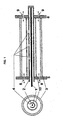
- FIG. 1 shows the transverse and longitudinal section of a device for generating microwave plasmas with a designed as a coaxial resonator microwave feed.
- the microwave feed contains an inner conductor (1), an outer conductor (2) and coupling points (4).
- the microwave feed is surrounded by an outer dielectric tube (3) which separates the microwave supplying area from the plasma chamber (not shown) and on the outside of which the plasma is formed.
- the outer dielectric Pipe (3) is connected to the walls (5, 6) gas or vacuum tight. Between the coaxial generator and the outer dielectric tube is inserted an inner dielectric tube (10) which is also gas or vacuum sealed to the walls (5, 6) and to the outer dielectric tube (3) a space separated from the microwave feed forms, through which a fluid can flow. The fluid can be supplied or removed via the openings (8) and (9).
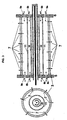
- FIG. 2 shows the transverse and longitudinal section of an embodiment of in FIG. 1 sketched device for the production of microwave plasmas, wherein the wall of the outer dielectric tube (3) has pores (7).
- the pores (7) are shown greatly enlarged in the drawing for clarity. Through these pores (7) gas can be passed through the outer dielectric tube in the plasma chamber. It passes through the tube wall of the outer dielectric tube (3), at which the field strength of the microwaves and thus the ionization of the plasma is greatest.
- FIG. 3 shows the transverse and longitudinal section of an embodiment of in FIG. 1 sketched device for the production of microwave plasmas, in which the microwave feed is surrounded by three nested tubes.
- This triple tube arrangement comprises an inner dielectric tube (10) which is surrounded by a central dielectric tube (11), which in turn is surrounded by the outer dielectric tube (3). All three dielectric tubes are connected to the walls (5, 6) gas or vacuum tight.
- a process gas can via the openings (8 a) and (9 a) on or be discharged and escape through pores (7) in the outer dielectric tube (3). Again, the pores (7) are shown greatly enlarged in the drawing for clarity.
- a fluid for cooling the assembly flows through the inner space between the middle dielectric tube (11) and the inner dielectric tube (10) and can be supplied and removed via the openings (8b) and (9b).
- FIG. 4 shows a cross section of an embodiment of the in FIG. 1 illustrated device in which the outer dielectric tube (3) by a metallic sheath (12) is surrounded.
- the angle of the metallic sheath in which the generation of the plasma takes place is limited to 180 °.
- FIG. 5 shows a longitudinal section of a device (20) as through FIG. 1 is described in the installed state in a plasma chamber (21).
- the cooling liquid (22) flows in this example through passages in the two end faces.
- the plasma is formed during operation.
- the cooling gas which is also the process gas, as indicated by the arrows (24), flows through the pipe wall in the space (23) and forms a plasma.
- Figures 6A and 6B show in perspective and in a cross section an embodiment (20) in which the largest part of the lateral surface of the outer dielectric tube is enclosed by a metal sheath (12), and a plasma (31), which indicated in the drawing by transparent arrows is, can only arise in a narrow area.
- a workpiece (30) which moves relative to the device can be treated in this area with plasma over a large area.
- All embodiments are powered by a microwave supply, not shown in the drawings, consisting of a microwave generator and possibly additional elements. These elements may e.g. Circulators, isolators, tuning elements (e.g., three-pin tuners or E / H tuners) and mode converters (e.g., rectangular to coaxial).
- a microwave supply not shown in the drawings, consisting of a microwave generator and possibly additional elements.
- These elements may e.g. Circulators, isolators, tuning elements (e.g., three-pin tuners or E / H tuners) and mode converters (e.g., rectangular to coaxial).
- the fields of application of the apparatus and the method described above are manifold.
- the plasma treatment is used for.
- As the coating, cleaning, modification and etching of workpieces for the treatment of medical implants, for textile treatment, for sterilization, for light generation, preferably in the spectral range infrared to ultraviolet, for the reaction of gases or for gas synthesis, and in the art for exhaust gas purification.
- the workpiece or gas to be treated is brought into contact with the plasma or the microwave radiation.
- the geometry of the workpieces to be treated is sufficient from flat substrates, fibers and webs to moldings of any shape.
Abstract
Description
Die Erfindung betrifft eine Vorrichtung zur Erzeugung von Mikrowellenplasmen hoher Plasmadichte, welche mindestens eine Mikrowelleneinspeisung aufweist, die von mindestens einem dielektrischen Rohr umgeben ist. Desweiteren wird ein Verfahren zur Erzeugung von Mikrowellenplasmen hoher Plasmadichte durch Verwendung dieser Vorrichtung beschrieben.The invention relates to a device for generating high plasma density microwave plasmas, which has at least one microwave feed, which is surrounded by at least one dielectric tube. Furthermore, a method of generating high plasma density microwave plasma by use of this device will be described.
Vorrichtungen zur Erzeugung von Mikrowellenplasmen werden bei der Plasmabehandlung von Werkstücken und Gasen eingesetzt. Die Plasmabehandlung dient z. B. der Beschichtung, Reinigung, Modifizierung und Ätzung von Werkstücken, zur Behandlung von medizinischen Implantaten, zur Textilbehandlung, zur Sterilisation, zur Lichterzeugung, bevorzugt im Spektralbereich Infrarot bis Ultraviolett, zur Umsetzung von Gasen oder zur Gassynthese sowie in der Technik zur Abgasreinigung. Dabei wird das zu behandelnde Werkstück oder Gas in Kontakt mit dem Plasma oder der Mikrowellenstrahlung gebracht.Devices for generating microwave plasmas are used in the plasma treatment of workpieces and gases. The plasma treatment is used for. As the coating, cleaning, modification and etching of workpieces, for the treatment of medical implants, for textile treatment, for sterilization, for light generation, preferably in the spectral range infrared to ultraviolet, for the implementation of gases or for gas synthesis and in the art for exhaust gas purification. In this case, the workpiece or gas to be treated is brought into contact with the plasma or the microwave radiation.
Die Geometrie der zu behandelnden Werkstücke reicht von flachen Substraten, Fasern und Bahnen bis zu Formteilen von beliebiger Gestalt.The geometry of the workpieces to be treated ranges from flat substrates, fibers and webs to moldings of any shape.
Die wichtigsten Prozessgase sind Edelgase, fluor- und chlorhaltige Gase, Kohlenwasserstoffe, Furane, Dioxine, Schwefelwasserstoffe, Sauerstoff, Wasserstoff, Stickstoff, Tetrafluormethan, Schwefelhexafluorid, Luft, Wasser und deren Mischungen. Bei der Abgasreinigung durch mikrowelleninduziertes Plasma besteht das Prozessgas aus Abgasen aller Art insbesondere Kohlenmonoxid, Kohlenwasserstoffe, Stickoxide, Aldehyde und Schwefeloxide. Diese Gase können jedoch ohne weiteres auch als Prozessgase für andere Anwendungen verwendet werden.The most important process gases are noble gases, fluorine- and chlorine-containing gases, hydrocarbons, furans, dioxins, hydrogen sulfide, oxygen, hydrogen, nitrogen, tetrafluoromethane, sulfur hexafluoride, air, water and their mixtures. In the exhaust gas cleaning by microwave induced Plasma consists of the process gas from exhaust gases of all kinds, in particular carbon monoxide, hydrocarbons, nitrogen oxides, aldehydes and sulfur oxides. However, these gases can readily be used as process gases for other applications.
Vorrichtungen, die Mikrowellenplasmen erzeugen, sind in den Dokumenten
Den oben angeführten Dokumenten ist gemein, dass sie eine Mikrowellenantenne im Inneren eines dielektrischen Rohres beschreiben. Werden im Inneren eines solchen Rohres Mikrowellen erzeugt, bilden sich entlang dessen Außenseite Oberflächenwwellen aus. Durch diese Oberflächenwellen wird in einem Prozessgas, welches unter niedrigem Druck steht, ein linear gestrecktes Plasma erzeugt. Typische niedere Drücke sind dabei 0,1 mbar - 10 mbar. Das im Inneren des dielektrischen Rohres liegende Volumen ist typischerweise auf Umgebungsdruck (im Allgemeinen Normaldruck; ca. 1013 mbar). Bei einigen Ausführungsformen wird zur Kühlung des dielektrischen Rohres ein Kühlgasstrom benutzt, der das Rohr durchströmt.The above-mentioned documents have in common that they describe a microwave antenna inside a dielectric tube. If microwaves are generated in the interior of such a tube, surface waves form along the outside thereof. These surface waves generate a linearly stretched plasma in a process gas which is under low pressure. Typical lower pressures are 0.1 mbar - 10 mbar. The volume inside the dielectric tube is typically at ambient pressure (generally normal pressure, about 1013 mbar). In some embodiments, a cooling gas flow through the tube is used to cool the dielectric tube.
Für die Zuleitung der Mikrowellen werden unter anderem Hohlleiter und Koaxialleiter, als Koppelstellen in der Wand der Plasmakammer werden unter anderem Antennen und Schlitze verwendet. Solche Zuleitungen für Mikrowellen und Koppelstellen werden zum Beispiel in
Die zur Erzeugung des Plasmas verwendeten Mikrowellenfrequenzen liegen vorzugsweise im Bereich von 800 MHz bis 2,5 GHz, besonders bevorzugt in den Bereichen 800 MHz bis 950 MHz und 2,0 - 2,5 GHz, jedoch kann die Mikrowellenfrequenz im gesamten Bereich von 10 MHz bis einigen 100 GHz liegen.The microwave frequencies used to generate the plasma are preferably in the range of 800 MHz to 2.5 GHz, more preferably in the ranges of 800 MHz to 950 MHz and 2.0-2.5 GHz, but the microwave frequency can be in the entire range of 10 MHz to some 100 GHz.
Mit einer Vorrichtung zur Erzeugung von homogenen Mikrowellenplasmen gemäß
Die Einsatzmöglichkeiten der oben genannten Plasmaquellen werden durch eine hohe Energieabgabe des Plasmas auf das dielektrische Rohr eingeschränkt. Durch diese Energieabgabe kann es zu einer übermäßigen Erwärmung des Rohres und letztendlich zu einer Zerstörung desselben kommen. Daher werden diese Quellen typischerweise mit Mikrowellenleistungen von ca. 1 - 2 kW bei entsprechend niedrigem Druck (ca. 0,1 - 0,5 mbar) betrieben. Die Prozessdrücke können zwar auch 1 mbar - 100 mbar betragen, jedoch nur unter bestimmten Bedingungen und entsprechend niedrigerer Leistung, um das Rohr nicht zu zerstören.The possible uses of the abovementioned plasma sources are limited by a high energy output of the plasma on the dielectric tube. This release of energy can lead to excessive heating of the tube and ultimately to its destruction. Therefore, these sources are typically operated with microwave power of about 1 - 2 kW at a correspondingly low pressure (about 0.1 - 0.5 mbar). The process pressures can Although also 1 mbar - 100 mbar be, but only under certain conditions and correspondingly lower power, so as not to destroy the pipe.
Mit den oben genannten Vorrichtungen lassen sich typische Plasmalängen von 0,5 - 1,5 m erreichen. Mit Plasmen aus nahezu 100% Argon lassen sich zwar auch größere Längen erzielen, jedoch sind solche Plasmen technisch wenig relevant.With the above-mentioned devices typical plasma lengths of 0.5 - 1.5 m can be achieved. Although larger lengths can be achieved with plasmas made from almost 100% argon, such plasmas are technically less relevant.
Ein weiteres Problem bei solchen Plasmaquellen liegt in der Prozessgasführung insbesondere bei höheren Prozessgasdrücken (größer als 1 mbar). Die Ursache hierfür liegt darin begründet, dass die Plasmadichte in zunehmender radialer Entfernung vom dielektrischen Rohr stark abnimmt. Dies erschwert die Zuführung von neuem Prozessgas zu den Bereichen hoher Ladungsträgerdichten. Desweiteren steigt bei höheren Prozessdrücken die auf das dielektrische Rohr abgegebene Wärmeleitung.Another problem with such plasma sources is in process gas control, especially at higher process gas pressures (greater than 1 mbar). The reason for this is due to the fact that the plasma density decreases sharply in increasing radial distance from the dielectric tube. This complicates the supply of new process gas to the areas of high carrier densities. Furthermore, at higher process pressures, the heat conduction emitted to the dielectric tube increases.
Höhere Prozessgasdrücke sind jedoch bevorzugt, da sie häufig zu deutlichen Steigerungen der Prozessgeschwindigkeiten, um das 10 bis 100-fache, führen.However, higher process gas pressures are preferred because they often result in significant process speed increases of 10 to 100 times.
Aufgabe der vorliegenden Erfindung ist es, die oben genannten Nachteile zu überwinden und so eine Steigerung der Plasmakonzentration und des Prozessgasdrucks zu erhalten.The object of the present invention is to overcome the abovementioned disadvantages and thus to obtain an increase in the plasma concentration and the process gas pressure.
Dies wird erfindungsgemäß durch eine Vorrichtung zur Erzeugung von Mikrowellenplasmen nach Anspruch 1 erreicht. Diese Vorrichtung weist mindestens eine Mikrowelleneinspeisung auf, die von einem inneren dielektrischen Rohr umgeben ist. Dieses innere dielektrische Rohr ist wiederum von mindestens einem äußeren dielektrischen Rohr umgeben. Dadurch wird ein Raum gebildet, der zur Aufnahme und Durchleitung eines Fluids geeignet ist.This is achieved according to the invention by a device for producing microwave plasmas according to claim 1. This device has at least one microwave feed, which is surrounded by an inner dielectric tube. This inner dielectric tube is in turn surrounded by at least one outer dielectric tube. Thereby a space is formed which is suitable for receiving and passing a fluid.
Die Vorrichtung ermöglicht in vorteilhafter Weise die Durchleitung eines Fluids durch die oben beschriebene Doppelrohranordnung, welches zur Kühlung oder der Zuführung zum Prozessgas verwendet werden kann.The device advantageously allows the passage of a fluid through the double-tube arrangement described above, which can be used for cooling or the supply to the process gas.
Geeignete Mikrowelleneinspeisungen sind dem Fachmann bekannt. Im Allgemeinen besteht eine Mikrowelleneinspeisung aus einer Struktur, die Mikrowellen in den Raum abstrahlen kann. Strukturen, die Mikrowellen abstrahlen, sind dem Fachmann bekannt und können durch alle bekannten Mikrowellenantennen und Resonatoren mit Koppelstellen zum Einkoppeln der Mikrowellenstrahlung in einen Raum realisiert werden. Bevorzugt für die beschriebene Vorrichtung sind Hohlraumresonatoren, Stabantennen, Schlitzantennen, Helixantennen und omnidirektionale Antennen. Besonders bevorzugt sind Koaxialresonatoren.Suitable microwave feeds are known to the person skilled in the art. In general, a microwave feed consists of a structure that can radiate microwaves into the room. Structures that radiate microwaves are known to those skilled in the art and can be implemented by all known microwave antennas and resonators with coupling points for coupling the microwave radiation into a room. Cavity resonators, rod antennas, slot antennas, helix antennas and omnidirectional antennas are preferred for the device described. Particularly preferred are coaxial resonators.
Die Mikrowelleneinspeisung ist im Betrieb über Mikrowellenzuleitungen (Hohlleiter oder Koaxialleiter) mit einem Mikrowellengenerator (z.B. Klystron oder Magnetron) verbunden. Zur Steuerung der Eigenschaften der Mikrowellen und zum Schutz der Elemente können noch Zirkulatoren, Isolatoren, Tuningelemente (z.B. Dreistifttuner oder E/H Tuner) sowie Modenkonverter (z.B. Rechteck- auf Koaxialleiter) in die Mikrowellenzuführung eingebracht werden.The microwave feed is connected in operation via microwave feeders (waveguide or coaxial) to a microwave generator (e.g., klystron or magnetron). To control the properties of the microwaves and protect the elements, circulators, isolators, tuning elements (e.g., three-pin tuners or E / H tuners) and mode converters (e.g., rectangular to coaxial) may also be incorporated into the microwave feed.
Die dielektrischen Rohre sind vorzugsweise langgestreckt. Dies bedeutet hier, dass das Verhältnis Rohrdurchmesser Rohrlänge zwischen 1:1 und 1:1000 liegt und vorzugsweise 1:10 bis 1:100 beträgt. Dabei können die beiden Rohre gleichlang sein oder eine unterschiedliche Länge aufweisen. Ferner sind die Rohre vorzugsweise gerade, können jedoch auch eine gebogene Form oder Ecken entlang ihrer Längsachse haben.The dielectric tubes are preferably elongate. This means here that the ratio pipe diameter pipe length is between 1: 1 and 1: 1000, and preferably 1:10 to 1: 100. The two tubes can be the same length or have a different length. Furthermore, the tubes are preferably straight, but may also have a curved shape or corners along their longitudinal axis.
Die Querschnittsfläche der Rohre ist vorzugsweise kreisrund, jedoch sind generell beliebige Flächenformen möglich. Beispiele für andere Flächenformen sind Ellipsen und Polygone.The cross-sectional area of the tubes is preferably circular, but generally any surface shapes are possible. Examples of other surface shapes are ellipses and polygons.
Die langgestreckte Form der Rohre bedingt ein langgestrecktes Plasma. Langgestreckte Plasmen haben den Vorteil, dass durch Bewegung der Plasmavorrichtung relativ zu einem flächigen Werkstück große Flächen in kurzer Zeit behandelt werden können.The elongated shape of the tubes requires an elongated plasma. Elongated plasmas have the advantage that, by moving the plasma apparatus relative to a flat workpiece, large areas can be treated in a short time.
Die dielektrischen Rohre sollten bei der gegebenen Mikrowellenfrequenz einen geringen dielektrischen Verlustfaktor tan δ für die benutzte Mikrowellenlänge aufweisen. Geringe dielektrische Verlustfalctoren tan δ liegen in dem Bereich 10-2 bis 10-7.The dielectric tubes should have a low dielectric loss factor tan δ for the microwave wavelength used at the given microwave frequency. Low dielectric loss factors tan δ are in the
Geeignete dielektrische Materialien für die dielektrischen Rohre sind Metalloxide, Halbmetalloxide, Keramiken, Kunststoffe und Verbundmaterialien aus diesen Stoffen. Besonders bevorzugt sind dielektrische Rohre aus Quarzglas oder Aluminiumoxyd mit dielektrischen Verlustfaktoren tan δ im Bereich 10-3 bis 10-4. Dabei können die dielektrischen Rohre aus demselben Material oder unterschiedlichen Materialien bestehen.Suitable dielectric materials for the dielectric tubes are metal oxides, semi-metal oxides, ceramics, plastics, and composites of these materials. Particular preference is given to dielectric tubes made of quartz glass or aluminum oxide with dielectric loss factors tan δ in the range from 10 -3 to 10 -4 . In this case, the dielectric tubes may consist of the same material or different materials.
Gemäß einer besonderen Ausführungsform sind die dielektrischen Rohre an den Stirnseiten mit Wänden verschlossen. Eine gas- oder vakuumdichte Verbindung zwischen den Rohren und den Wänden ist dabei vorteilhaft. Verbindungen zwischen zwei Werkstücken sind dem Fachmann bekannt und können zum Beispiel Klebe-, Schweiß-, Klemm- oder Schraubverbindungen sein. Die Dichtigkeit der Verbindung kann von gasdicht bis vakuumdicht reichen, wobei vakuumdicht, je nach Arbeitsumgebung, Dichtigkeit im Grobvakuum (300 - 1 hPa), Feinvakuum (1 - 10-3 hPa), Hochvakuum (10-3 - 10-7 hPa) oder Ultrahochvakuum (10-7 - 10-12 hPa) bedeutet. Im Allgemeinen bedeutet vakuumdicht hier eine Dichtigkeit im Grob- oder Feinvakuum.According to a particular embodiment, the dielectric tubes are closed at the end faces with walls. A gas- or vacuum-tight connection between the pipes and the walls is advantageous. Connections between two workpieces are known to the person skilled in the art and can be, for example, adhesive, welding, clamping or screw connections. The tightness of the compound can range from gas-tight to vacuum-tight, being vacuum tight, depending on the working environment, tightness in a rough vacuum (300 - 1 hPa), fine vacuum (1 - 10 -3 hPa), high vacuum (10 -3 - 10 -7 hPa) or Ultra-high vacuum (10 -7 - 10 -12 hPa) means. In general, vacuum-tight here means tightness in coarse or fine vacuum.
Die Wände können Durchlässe aufweisen, durch die ein Fluid geleitet werden kann. Dabei ist die Größe und Form der Durchlässe beliebig. Je nach Anwendung kann jede Wand mindestens einen Durchlass enthalten. Bei einer bevorzugten Ausführungsform befinden sich in dem Bereich, den die Stirnseite des inneren dielektrischen Rohres abdeckt, keine Durchlässe.The walls may have passages through which a fluid can be passed. The size and shape of the passages is arbitrary. Depending on the application, each wall can contain at least one passage. In a preferred embodiment, there are no passages in the area covered by the end face of the inner dielectric tube.
Das Fluid wird durch den Raum zwischen dem äußeren dielektrischen Rohr und dem inneren dielektrischen Rohr geleitet und über die Öffnungen in den Wänden an den Stirnseiten des dielektrischen Rohres zu- beziehungsweise abgeführt. Die Durchstömungsgeschwindigkeit und das Durchströmverhalten (laminar oder turbulent) des dielektrischen Fluids durch das dielektrische Rohr ist so zu wählen, dass das Fluid, besonders wenn es sich um eine Flüssigkeit handelt, einen guten Kontakt mit dem Rand des dielektrischen Rohres hat und es zusätzlich bei flüssigen Fluiden zu keiner Verdampfung der dielektrischen Flüssigkeit kommt. Die Regelung der Durchströmgeschwindigkeit und des Durchströmverhaltens mittels des Drucks und der Form und Größe der Durchlässe ist dem Fachmann bekannt.The fluid is passed through the space between the outer dielectric tube and the inner dielectric tube and is delivered through the openings in the walls at the end faces of the dielectric tube. The flow rate and flow behavior (laminar or turbulent) of the dielectric fluid through the dielectric tube should be chosen so that the fluid, especially if it is a liquid, has good contact with the edge of the dielectric tube and, in addition, liquid Fluids come to no evaporation of the dielectric fluid. The regulation of the flow rate and the Durchströmverhaltens by means of the pressure and the shape and size of the passages is known in the art.
Als dielektrisches Fluid kann sowohl ein Gas als auch eine dielektrische Flüssigkeit verwendet werden.As the dielectric fluid, both a gas and a dielectric liquid may be used.
Jedoch ist eine Kühlung des dielektrischen Rohres durch ein Fluid nicht in einfacher Weise zu realisieren, da der Energieeintrag der Mikrowellen auf das Fluid dieses erwärmt. Durch jede zusätzliche Aufheizung des Fluids wird der Kühleffekt auf das dielektrische Rohr vermindert. Diese Verminderung der Kühlleistung kann bei hoher Mikrowellenabsorption des Fluids auch zu einer negativen Kühlleistung führen. Dies entspricht einer zusätzlichen Erwärmung des dielektrischen Rohres.However, a cooling of the dielectric tube by a fluid can not be realized in a simple manner, since the energy input of the microwaves to the fluid heats the latter. Each additional heating of the fluid reduces the cooling effect on the dielectric tube. This reduction in cooling performance can also lead to negative cooling performance with high microwave absorption of the fluid. This corresponds to an additional heating of the dielectric tube.
Um eine Aufheizung des Fluids durch die Mikrowellen möglichst gering zu halten, muss das Fluid bei der Wellenlänge der Mikrowellen einen niedrigen dielektrischen Verlustfaktor tan δ im Bereich 10-2 bis 10-7 aufweisen. Hierdurch wird ein Mikrowellenleistungseintrag in das Fluid vermieden bzw. auf ein tolerierbares Maß reduziert.In order to minimize heating of the fluid by the microwaves, the fluid must have a low dielectric loss factor tan δ in the
Flüssige Fluide bieten aufgrund des größeren Wärmekoeffizienten eine größere Aufnahme der Wärmeleistung als gasförmige Fluide.Due to the larger heat coefficient, liquid fluids offer a greater absorption of heat output than gaseous fluids.
Eine solche dielektrische Flüssigkeit ist zum Beispiel ein isolierendes Öl mit einem niedrigen dielektrischen Verlustfaktor. Isolierende Öle sind zum Beispiel Mineralöle, Olefine (z.B. Polyalphaolefin) oder Silikonöle (z.B. Coolanol® oder Dimethylpolysiloxane). Bevorzugt als dielektrische Flüssigkeit ist Hexadimethylsiloxan.Such a dielectric fluid is, for example, an insulating oil having a low dielectric loss factor. Insulating oils are, for example, mineral oils, olefins (eg polyalphaolefin) or silicone oils (eg Coolanol® or dimethylpolysiloxanes). Preferred as a dielectric liquid is hexadimethylsiloxane.
Durch diese Fluid-Kühlung des äußeren dielektrischen Rohres ist es möglich, die Aufheizung des äußeren dielektrischen Rohres zu vermindern. Dadurch werden höhere Mikrowellenleistungen ermöglicht, die wiederum zu einer Steigerung der Konzentration des Plasmas an der Außenseite des äußeren dielektrischen Rohres führen. Desweiteren wird durch die Kühlung ein höherer Prozessdruck möglich als in ungekühlten Plasmaerzeugern.By this fluid cooling of the outer dielectric tube, it is possible to reduce the heating of the outer dielectric tube. This allows higher microwave powers, which in turn lead to an increase in the concentration of the plasma on the outside of the outer dielectric tube. Furthermore, a higher process pressure is possible by the cooling than in uncooled plasma generators.
Im Gegensatz zu einer Gaskühlung gemäß
Bei einer bevorzugten Ausführungsform wird erfindungsgemäß das Material des äußeren dielektrischen Rohres durch ein poröses dielektrisches Material ersetzt. Geeignete poröse dielektrische Materialien sind Keramiken oder gesinterte Dielektrika, bevorzugt Aluminiumoxid. Es ist jedoch auch möglich, Rohrwandungen aus Quarzglas oder Metalloxiden mit kleinen Löchern zu versehen.In a preferred embodiment, according to the invention, the material of the outer dielectric tube is replaced by a porous dielectric material. Suitable porous dielectric materials are ceramics or sintered dielectrics, preferably alumina. However, it is also possible to provide pipe walls made of quartz glass or metal oxides with small holes.
Bei dem Durchfluss eines Gases zwischen den dielektrischen Rohren entweicht nun ein Teil des Gases durch diese Poren. Da an der Oberfläche des äußeren dielektrischen Rohres die höchsten Mikrowellenfeldstärken herrschen, durchwandern die Gasmoleküle beim Durchgang durch das äußere dielektrische Rohr die Zone der höchsten Ionendichte.With the passage of a gas between the dielectric tubes, some of the gas now escapes through these pores. Since the highest microwave field strengths prevail on the surface of the outer dielectric tube, the Gas molecules, when passing through the outer dielectric tube, the zone of highest ion density.
Desweiteren besitzt das Gas nach dem Durchgang durch die Poren eine resultierende Bewegungsrichtung radial vom Rohr weg.Furthermore, after passage through the pores, the gas has a resultant direction of movement radially away from the tube.
Wird zur Kühlung das gleiche Gas benutzt, das auch als Prozessgas verwendet wird, wird der Anteil der angeregten Teilchen durch die Passage des Prozessgases durch den Bereich größter Mikrowellenintensität gesteigert. Dadurch ist auf diese Weise ein effizienter Transport von angeregten Teilchen zum Werkstück gewährleistet. Dies steigert sowohl die Konzentration als auch den Fluss der angeregten Teilchen.If the same gas used for cooling, which is also used as a process gas, the proportion of excited particles is increased by the passage of the process gas through the range of maximum microwave intensity. This ensures an efficient transport of excited particles to the workpiece in this way. This increases both the concentration and the flux of excited particles.
Eine solche Anordnung ist des Weiteren ebenfalls besonders gut geeignet, um reine Gaskonversionsprozesse wie Abgasreinigung oder Gassyntheseprozesse durchzuführen. Weitere Prozessgase lassen sich gegebenenfalls durch weitere poröse Rohre der Prozesskammer zuführen.Furthermore, such an arrangement is also particularly well suited for carrying out pure gas conversion processes such as exhaust gas purification or gas synthesis processes. Additional process gases can optionally be fed through further porous tubes of the process chamber.
Durch die Porosität des äußeren dielektrischen Rohres und den Gasdruck wird der Fluss (Moleküle pro Fläche pro Zeit) des Prozessgases oder Prozessgasgemischs durch das äußere dielektrische Rohr geregelt.The porosity of the outer dielectric tube and the gas pressure control the flow (molecules per unit area per time) of the process gas or process gas mixture through the outer dielectric tube.
Desweiteren müssen bei diesem Abgasreinigungsverfahren alle Gasmoleküle die Rohrwand und damit den Bereich höchster Ionendichte passieren. Dies stellt einen vorteil gegenüber gängigen Verfahren dar, bei denen sich die Brennkammer im Inneren eines Volumens befindet, und die Mikrowellen von außen eingestrahlt werden. Der Anteil des gereinigten Abgases ist bei einem gängigen Verfahren geringer als bei dem hier vorgestellten, da bei einem solchen gängigen Verfahren Teile des Gases, die sich in der Nähe der Wände des Volumens befinden, aufgrund der dort herrschenden niedrigen Feldstärken nicht ionisiert werden.Furthermore, in this exhaust gas purification process all gas molecules must pass through the tube wall and thus the region of highest ion density. This is an advantage over current methods, in which the combustion chamber is located inside a volume, and the microwaves are radiated from the outside. The proportion of purified exhaust gas is less in a conventional method than that presented here, as in such a common method Parts of the gas, which are located near the walls of the volume, are not ionized due to the low field strengths prevailing there.
Als Prozessgas kann jedes bekannte Gas genutzt werden. Die wichtigsten Prozessgase sind Edelgase, fluor- und chlorhaltige Gase, Kohlenwasserstoffe, Furane, Dioxine, Schwefelwasserstoffe, Sauerstoff, Wasserstoff, Stickstoff, Tetrafluormethan, Schwefelhexafluorid, Luft, Wasser und deren Mischungen. Bei der Abgasreinigung durch mikrowelleninduziertes Plasma besteht das Prozessgas aus Abgasen aller Art insbesondere Kohlenmonoxid, Kohlenwasserstoffe, Stickoxide, Aldehyde und Schwefeloxide. Diese Gase können jedoch ohne weiteres auch als Prozessgase für andere Anwendungen verwendet werden.As a process gas, any known gas can be used. The most important process gases are noble gases, fluorine- and chlorine-containing gases, hydrocarbons, furans, dioxins, hydrogen sulfide, oxygen, hydrogen, nitrogen, tetrafluoromethane, sulfur hexafluoride, air, water and their mixtures. In the exhaust gas purification by microwave-induced plasma, the process gas from exhaust gases of all kinds in particular carbon monoxide, hydrocarbons, nitrogen oxides, aldehydes and sulfur oxides. However, these gases can readily be used as process gases for other applications.
Gemäß einer weiteren Ausführungsform kann ein weiteres dielektrisches Rohr innerhalb des äußeren dielektrischen Rohres eingebracht werden, das das innere dielektrische Rohr umgibt und ebenfalls an seinen Stirnseiten gas- oder vakuumdicht mit den Wänden verbunden ist. In dieser Ausführungsform wird der Raum zwischen dem äußeren dielektrischen Rohr und dem inneren dielektrischen Rohr in einen äußeren- und einen inneren Raum geteilt.According to a further embodiment, a further dielectric tube may be introduced within the outer dielectric tube which surrounds the inner dielectric tube and is also connected at its end faces gas-tight or vacuum-tight to the walls. In this embodiment, the space between the outer dielectric tube and the inner dielectric tube is divided into outer and inner spaces.
Wird nun das Prozessgas durch den äußeren Raum geleitet, und ein Fluid durch den inneren Raum geleitet, ist eine Kühlung des inneren dielektrischen Rohres und der Mikrowellenstruktur möglich. Dies wiederum ermöglicht eine höhere Prozessleistung. Das Fluid sollte dabei die Mikrowellen nicht absorbieren. Insbesondere bei der Verwendung einer Flüssigkeit als Fluid sollte die Flüssigkeit für die benutzte Mikrowellenlänge einen geringen dielektrischen Verlustfaktor tan δ im Bereich 10-2 bis 10-7 aufweisen.Now, when the process gas is passed through the outer space, and a fluid passed through the inner space, a cooling of the inner dielectric tube and the microwave structure is possible. This in turn allows for higher process performance. The fluid should not absorb the microwaves. In particular, when using a liquid as a fluid, the liquid should be used for the Microwave length have a low dielectric loss factor tan δ in the
Um den Mikrowellenleistungsbedarf bei den oben aufgeführten Plasmaquellen weiter zu reduzieren, kann gemäß einer weiteren bevorzugten Ausführungsform eine metallische Ummantelung um das äußere dielektrische Rohr angebracht werden, welches dieses Rohr partiell abdeckt. Diese metallische Ummantelung wirkt dabei als Mikrowellenabschirmung und kann z.B. aus einem Metallrohr, einem gebogenen Metallblech, einer Metallfolie oder auch aus einer metallischen Schicht bestehen und aufgesteckt, aufgalvanisiert oder auf eine andere Weise aufgebracht sein. Solche metallischen Mikrowellenabschirmungen können den Windelbereich, in dem die Erzeugung des Plasmas stattfindet, beliebig begrenzen (z.B. auf 90°, 180° oder 270°) und so den Leistungsbedarf entsprechend reduzieren.In order to further reduce the microwave power requirement in the above-mentioned plasma sources, according to a further preferred embodiment, a metallic sheathing may be applied around the outer dielectric tube which partially covers this tube. This metallic sheath acts as a microwave shield and can e.g. consist of a metal tube, a bent metal sheet, a metal foil or even of a metallic layer and plugged, galvanized or applied in any other way. Such metallic microwave shields can arbitrarily limit the diaper area in which generation of the plasma takes place (e.g., at 90 °, 180 °, or 270 °) and thus reduce power requirements accordingly.
Insbesondere bei der Ausführungsform mit einer metallischen Ummantelung der Vorrichtungen zur Erzeugung von Mikrowellenplasmen ist es möglich, breite Werkstoffbahnen mit nur geringer verlustleistung mit einem Plasma zu behandeln. Durch die Ummantelung wird der Raumbereich der Vorrichtung, der dem Werkstück nicht zugewandt ist, abgeschirmt, und nur ein schmaler Plasmastreifen zwischen Werkstück und Vorrichtung über die gesamte Breite des Werkstückes erzeugt.In particular, in the embodiment with a metallic sheath of the devices for the production of microwave plasmas, it is possible to treat wide webs of material with only a small loss of power with a plasma. Through the jacket, the space region of the device, which is not facing the workpiece, shielded, and only produces a narrow strip of plasma between the workpiece and the device over the entire width of the workpiece.
Alle oben beschriebenen Vorrichtungen zur Erzeugung von Plasmen bilden während des Betriebs an der Haubenseite des dielektrischen Rohres ein Plasma aus. Im Normalfall wird die Vorrichtung im Inneren eines Raumes (Plasmakammer) betrieben. Diese Plasmakamaner kann je nach Betriebsart verschiedene Formen und Öffnungen aufweisen und verschiedene Funktionen erfüllen. Zum Beispiel kann die Plasmakammer das zu bearbeitende Werkstück und das Prozessgas enthalten (direkter Plasmaprozess) oder Prozessgase und Öffnungen für den Plasmaaustritt aufweisen (remote-Plasmaprozess, Abgasreinigung).All the above-described devices for producing plasmas form a plasma during operation on the hood side of the dielectric tube. Normally, the device is operated inside a room (plasma chamber). Depending on the mode of operation, these plasma kayakers can have different shapes and openings and fulfill different functions. For example, the plasma chamber can contain the workpiece to be machined and the process gas (direct plasma process) or process gases and openings for the plasma exit have (remote plasma process, exhaust gas purification).
Bei einem Verfahren zur Erzeugung Mikrowellenplasmen in einer oben beschriebenen Vorrichtung wird ein Fluid durch den Raum zwischen dem inneren dielektrischen Rohr und dem äußeren dielektrischen Rohr, vorzugsweise durch Durchlässe in den Wänden, geleitet. Das Fluid kann dabei ein Gas oder eine Flüssigkeit sein.In a method of generating microwave plasmas in a device as described above, a fluid is passed through the space between the inner dielectric tube and the outer dielectric tube, preferably through passages in the walls. The fluid may be a gas or a liquid.
Der Druck des Fluids kann dabei größer, kleiner oder gleich dem Atmosphärendruck sein.The pressure of the fluid may be greater than, less than or equal to the atmospheric pressure.
In einer vorteilhaften Ausführung wird ein gasförmiges Fluid, vorzugsweise ein Prozessgas, besonders bevorzugt ein Abgas, durch das poröse Rohr der oben beschriebenen Vorrichtung mit einem porösen äußernen Rohr geleitet und so einem Plasmaprozess zugeführt. Das Fluid hat dabei bevorzugt einen geringen dielektrischen Verlustfaktor tan δ im Bereich 10-2 bis 10-7.In an advantageous embodiment, a gaseous fluid, preferably a process gas, particularly preferably an exhaust gas, is passed through the porous tube of the device described above with a porous outer tube and supplied to a plasma process. The fluid preferably has a low dielectric loss factor tan δ in the
In einer weiteren vorteilhaften Ausführung fließt in der oben beschriebenen Vorrichtung, welche ein inneres mittleres und äußere dielektrische Rohr enthält, fließt in dem Raum zwischen dem äußeren dielektrischen Rohr und dem mittleren dielektrischen Rohr ein Gas, welches vorzugsweise ein Prozessgas ist, und in dem Raum zwischen dem inneren dielektrischen Rohr und dem mittleren dielektrischen Rohr ein Fluid; welches vorzugsweise einen geringen dielektrischen Verlustfaktor tan δ hat. Das äußere dielektrische Rohr weist dabei vorzugsweise eine poröse Wand auf.In a further advantageous embodiment, in the apparatus described above, which includes an inner middle and outer dielectric tube, in the space between the outer dielectric tube and the middle dielectric tube flows a gas, which is preferably a process gas, and in the space between the inner dielectric Pipe and the middle dielectric tube a fluid; which preferably has a low dielectric loss factor tan δ. The outer dielectric tube preferably has a porous wall.
Die Erfindung wird nachfolgend anhand der in den Zeichnungen schematisch dargestellten Ausführungsformen beispielhaft erläutert.
-
Figur 1 zeigt Schnittzeichnungen der oben beschriebenen Vorrichtung. -
Figur 2 zeigt Schnittzeichnungen der oben beschriebenen Vorrichtung mit porösem äußerem dielektrischem Rohr. -
Figur 3 -
Figur 4 zeigt eine Ausführungsform mit einer metallischen Ummantelung. -
Figur 5 -
Figuren 6A und 6B zeigen eine mögliche Ausführungsform zur Behandlung großflächiger Werkstücke.
-
FIG. 1 shows sectional drawings of the device described above. -
FIG. 2 shows sectional views of the device described above with porous outer dielectric tube. -
FIG. 3 shows sectional drawings of the device described above with additional cooling. -
FIG. 4 shows an embodiment with a metallic sheath. -
FIG. 5 shows a sectional view of the device described above installed in a plasma chamber. -
Figures 6A and 6B show a possible embodiment for the treatment of large-scale workpieces.
abgeführt werden und durch Poren (7) im äußeren dielektrischen Rohr (3) austreten. Auch hier sind die Poren (7) in der Zeichnung zur besseren Darstellung stark vergrößert dargestellt. Ein Fluid zum Kühlen der Anordnung fließt durch den inneren Raum zwischen dem mittleren dielektrischen Rohr (11) und dem inneren dielektrischen Rohr (10) und kann über die Öffnungen (8b) und (9b) zu- bzw. abgeführt werden.
be discharged and escape through pores (7) in the outer dielectric tube (3). Again, the pores (7) are shown greatly enlarged in the drawing for clarity. A fluid for cooling the assembly flows through the inner space between the middle dielectric tube (11) and the inner dielectric tube (10) and can be supplied and removed via the openings (8b) and (9b).
In einer bevorzugten Ausführungsform, in der das äußere dielektrische Rohr (3) eine poröse Rohrwand aufweist, wie in
Alle Ausführungsformen werden von einer in den Zeichnungen nicht dargestellten Mikrowellenzufuhr, bestehend aus einem Mikrowellengenerator und ggf. zusätzlichen Elementen, gespeist. Diese Elemente können z.B. Zirkulatoren, Isolatoren, Tuningelemente (z.B. Dreistifttuner oder E/H Tuner) sowie Modenkonverter (z.B. Rechteck- auf Koaxialleiter) beinhalten.All embodiments are powered by a microwave supply, not shown in the drawings, consisting of a microwave generator and possibly additional elements. These elements may e.g. Circulators, isolators, tuning elements (e.g., three-pin tuners or E / H tuners) and mode converters (e.g., rectangular to coaxial).
Die Einsatzgebiete der oben beschriebenen Vorrichtung und des oben beschriebenen Verfahrens sind mannigfaltig. Die Plasmabehandlung dient z. B. der Beschichtung, Reinigung, Modifizierung und Ätzung von Werkstücken, zur Behandlung von medizinischen Implantaten, zur Textilbehandlung, zur Sterilisation, zur Lichterzeugung, bevorzugt im Spektralbereich Infrarot bis Ultraviolett, zur Umsetzung von Gasen oder zur Gassynthese, sowie in der Technik zur Abgasreinigung. Dabei wird das zu behandelnde Werkstück oder Gas in Kontakt mit dem Plasma oder der Mikrowellenstrahlung gebracht. Die Geometrie der zu behandelnden Werkstücke reicht von flachen Substraten, Fasern und Bahnen bis zu Formteilen von beliebiger Gestalt.The fields of application of the apparatus and the method described above are manifold. The plasma treatment is used for. As the coating, cleaning, modification and etching of workpieces, for the treatment of medical implants, for textile treatment, for sterilization, for light generation, preferably in the spectral range infrared to ultraviolet, for the reaction of gases or for gas synthesis, and in the art for exhaust gas purification. In this case, the workpiece or gas to be treated is brought into contact with the plasma or the microwave radiation. The geometry of the workpieces to be treated is sufficient from flat substrates, fibers and webs to moldings of any shape.
Durch die Erhöhung der Plasmadichte und der Plasmaleistung sind dabei höhere Prozessgeschwindigkeiten als in Vorrichtungen und Verfahren des Standes der Technik möglich.By increasing the plasma density and the plasma power thereby higher process speeds are possible than in devices and methods of the prior art.
Claims (15)
- Device for generating microwave plasmas, comprising at least one microwave feed that is surrounded by an outer dielectric tube (3), wherein said microwave feed is surrounded, in addition, by at least one inner dielectric tube (10) that extends inside the outer dielectric tube (3) whereby a space is formed that is suitable for receiving and conducting a fluid, characterised in that both dielectric tubes (3, 10) are connected at their end faces with walls (5, 6), and that each of the walls (5, 6) has at least one passage (8, 9) for the fluid.
- Device according to claim 1, characterised in that there are no passages in the region that is covered by the end face of the inner dielectric tube.
- Device according to any one of the preceding claims, characterised in that the outer dielectric tube is porous or gas-permeable in at least a portion of the lateral surface or in the region of the entire lateral surface.
- Device according to any one of the preceding claims, characterised in that the inner dielectric tube (10) is surrounded by a middle dielectric tube (11) that extends inside the outer dielectric tube (3).
- Device according to any one of the preceding claims, characterised in that the outer dielectric tube (3) is partially surrounded by a metal jacket (12).
- Device according to any one of the preceding claims, characterised in that the metal jacket (12) leaves free a region of the lateral surface of the outer dielectric tube (3), which region preferably extends over the entire length of the dielectric tube (3).
- Device according to any one of the preceding claims, characterised in that the microwave feed is a microwave antenna or a cavity resonator with coupling points, preferably a coaxial resonator, and in that the microwave feed is connected, via microwave feed lines, preferably hollow waveguides or coaxial conductors, with a microwave generator, preferably a klystron or magnetron.
- Method for generating microwave plasmas in a device comprising at least one microwave feed that is surrounded by an inner dielectric tube (10), which, in turn, is surrounded by an outer dielectric tube (3), wherein a fluid is conducted through the space between the inner dielectric tube (10) and the outer dielectric tube (3), characterised in that both dielectric tubes (3, 10) are connected at their end faces with walls (5, 6), said walls having passages (8, 9), and that said fluid is conducted through the passages (8, 9).
- Method according to claim 8, characterised in that the fluid is, or contains, a liquid or a gas and that the fluid has a low dielectric loss factor tan δ in the range of from 10-2 to 10-7.
- Method according to claim 9, characterised in that the outer dielectric tube (3) consists of a porous or gas-permeable material, and that the gas, which is passed through the space between the inner dielectric tube (10) and the outer dielectric tube (3), is fed, through the outer dielectric tube (3), to a plasma process.
- Method according to claim 10, characterised in that at least one process gas or at least one waste gas is supplied to the plasma process.
- Method according to any one of claims 8 to 11, characterised in that the gas pressure in the space between the inner dielectric tube (10) and the outer dielectric tube (3) is higher than the atmospheric pressure or is equal to the atmospheric pressure.
- Method according to any one of claims 8 to 11, characterised in that the gas pressure in the space between the inner dielectric tube (10) and the outer dielectric tube (3) is lower than the atmospheric pressure.
- Method according to any one of claims 8 to 13, characterised in that the inner dielectric tube (10) is surrounded by a middle dielectric tube (11) which extends inside the outer dielectric tube (3), and that a gas passes through the space between the outer dielectric tube (3) and the middle dielectric tube (11), and that a fluid passes through the space between the inner dielectric tube (10) and the middle dielectric tube (11).
- Use of a device according to any one of claims 1 to 7 for generating a plasma for coating, cleaning, modifying and etching workpieces, for treating medical implants, for treating textiles, for sterilisation, for light generation, preferably in the infrared to ultraviolet spectral region, for converting gases or for gas synthesis, as well as in waste gas purification technology.
Applications Claiming Priority (2)
| Application Number | Priority Date | Filing Date | Title |
|---|---|---|---|
| DE102006048814.8A DE102006048814B4 (en) | 2006-10-16 | 2006-10-16 | Apparatus and method for generating high plasma density microwave plasmas |
| PCT/EP2007/008839 WO2008046552A1 (en) | 2006-10-16 | 2007-10-11 | Device and method for producing microwave plasma with a high plasma density |
Publications (2)
| Publication Number | Publication Date |
|---|---|
| EP2080424A1 EP2080424A1 (en) | 2009-07-22 |
| EP2080424B1 true EP2080424B1 (en) | 2011-07-06 |
Family
ID=38961952
Family Applications (1)
| Application Number | Title | Priority Date | Filing Date |
|---|---|---|---|
| EP07818910A Not-in-force EP2080424B1 (en) | 2006-10-16 | 2007-10-11 | Device and method for producing microwave plasma with a high plasma density |
Country Status (7)
| Country | Link |
|---|---|
| US (1) | US20100301012A1 (en) |
| EP (1) | EP2080424B1 (en) |
| AT (1) | ATE515931T1 (en) |
| AU (1) | AU2007312619A1 (en) |
| CA (1) | CA2666125A1 (en) |
| DE (1) | DE102006048814B4 (en) |
| WO (1) | WO2008046552A1 (en) |
Cited By (1)
| Publication number | Priority date | Publication date | Assignee | Title |
|---|---|---|---|---|
| DE102011111884B3 (en) * | 2011-08-31 | 2012-08-30 | Martin Weisgerber | Device for generating thermodynamic cold plasma by microwaves, has resonance chambers distributed in evacuated, electrically conductive anode, where plasma is generated by microwaves under standard atmospheric conditions |
Families Citing this family (14)
| Publication number | Priority date | Publication date | Assignee | Title |
|---|---|---|---|---|
| DE102008018902A1 (en) * | 2008-04-14 | 2009-10-15 | Iplas Innovative Plasma Systems Gmbh | Apparatus and method for internal surface treatment of hollow bodies |
| DE102008036766B4 (en) | 2008-08-07 | 2013-08-01 | Alexander Gschwandtner | Apparatus and method for generating dielectric layers in microwave plasma |
| CN102859034B (en) * | 2010-04-30 | 2015-04-29 | 应用材料公司 | Vertical inline CVD system |
| US9820372B2 (en) | 2012-01-27 | 2017-11-14 | Applied Materials, Inc. | Segmented antenna assembly |
| DE102012103425A1 (en) * | 2012-04-19 | 2013-10-24 | Roth & Rau Ag | Microwave plasma generating device and method of operation thereof |
| CH707920A1 (en) * | 2013-04-19 | 2014-10-31 | Philippe Odent | Molecular rotary inducer. |
| JP6277398B2 (en) * | 2013-08-27 | 2018-02-14 | 株式会社ユーテック | Plasma CVD apparatus and film forming method in piping |
| GB2536485A (en) * | 2015-03-19 | 2016-09-21 | Kouzaev Guennadi | Scalable reactor for microwave-and ultrasound-assisted chemistry |
| KR101830007B1 (en) * | 2016-11-11 | 2018-02-19 | 한국기초과학지원연구원 | COAXIAL CABLE COUPLED and WATER-COOLED TYPE SURFACE WAVE PLASMA GENERATING APPARATUS |
| JP6996096B2 (en) * | 2017-03-17 | 2022-01-17 | 日新電機株式会社 | Plasma processing equipment |
| KR20190015666A (en) * | 2017-08-04 | 2019-02-14 | 세메스 주식회사 | Substrate processing apparatus and method |
| DE102018113444B3 (en) | 2018-06-06 | 2019-10-10 | Meyer Burger (Germany) Gmbh | Linear microwave plasma source with separate plasma spaces |
| CN109302791B (en) * | 2018-10-26 | 2023-08-22 | 中国科学院合肥物质科学研究院 | Microwave antenna regulation and control magnetic enhancement linear plasma source generation system |
| CN112996209B (en) * | 2021-05-07 | 2021-08-10 | 四川大学 | Structure and array structure for microwave excitation of atmospheric pressure plasma jet |
Family Cites Families (11)
| Publication number | Priority date | Publication date | Assignee | Title |
|---|---|---|---|---|
| JPS56136646A (en) * | 1980-03-26 | 1981-10-26 | Toshiba Corp | Treating apparatus for surface of microwave plasma |
| DE4136297A1 (en) * | 1991-11-04 | 1993-05-06 | Plasma Electronic Gmbh, 7024 Filderstadt, De | Localised plasma prodn. in treatment chamber - using microwave generator connected to coupling device which passes through the wall of the chamber without using a coupling window |
| DE4235914A1 (en) * | 1992-10-23 | 1994-04-28 | Juergen Prof Dr Engemann | Device for generating microwave plasmas |
| DE19503205C1 (en) * | 1995-02-02 | 1996-07-11 | Muegge Electronic Gmbh | Device for generating a plasma in low pressure container e.g. for hardware items surface treatment by plasma etching and plasma deposition |
| US5597624A (en) * | 1995-04-24 | 1997-01-28 | Ceram Optic Industries, Inc. | Method and apparatus for coating dielectrics |
| DE29623199U1 (en) * | 1996-03-08 | 1998-04-02 | Spitzl Ralf Dr | Device for generating powerful microwave plasmas |
| DE19722272A1 (en) * | 1997-05-28 | 1998-12-03 | Leybold Systems Gmbh | Device for generating plasma |
| DE19726663A1 (en) * | 1997-06-23 | 1999-01-28 | Sung Spitzl Hildegard Dr Ing | Device for generating homogeneous microwave plasmas |
| DE19848022A1 (en) * | 1998-10-17 | 2000-04-20 | Leybold Systems Gmbh | Plasma generator has conductor fed through vacuum chamber in insulating tube of greater diameter, with tube ends sealed with respect to chamber walls, and conductor ends connected to AC field source |
| US6896854B2 (en) * | 2002-01-23 | 2005-05-24 | Battelle Energy Alliance, Llc | Nonthermal plasma systems and methods for natural gas and heavy hydrocarbon co-conversion |
| US20060156983A1 (en) * | 2005-01-19 | 2006-07-20 | Surfx Technologies Llc | Low temperature, atmospheric pressure plasma generation and applications |
-
2006
- 2006-10-16 DE DE102006048814.8A patent/DE102006048814B4/en not_active Expired - Fee Related
-
2007
- 2007-10-11 AU AU2007312619A patent/AU2007312619A1/en not_active Abandoned
- 2007-10-11 WO PCT/EP2007/008839 patent/WO2008046552A1/en active Application Filing
- 2007-10-11 US US12/311,810 patent/US20100301012A1/en not_active Abandoned
- 2007-10-11 CA CA002666125A patent/CA2666125A1/en not_active Abandoned
- 2007-10-11 AT AT07818910T patent/ATE515931T1/en active
- 2007-10-11 EP EP07818910A patent/EP2080424B1/en not_active Not-in-force
Cited By (2)
| Publication number | Priority date | Publication date | Assignee | Title |
|---|---|---|---|---|
| DE102011111884B3 (en) * | 2011-08-31 | 2012-08-30 | Martin Weisgerber | Device for generating thermodynamic cold plasma by microwaves, has resonance chambers distributed in evacuated, electrically conductive anode, where plasma is generated by microwaves under standard atmospheric conditions |
| WO2013029593A2 (en) | 2011-08-31 | 2013-03-07 | Martin Weisgerber | Apparatus for generating thermodynamically cold microwave plasma |
Also Published As
| Publication number | Publication date |
|---|---|
| DE102006048814B4 (en) | 2014-01-16 |
| US20100301012A1 (en) | 2010-12-02 |
| EP2080424A1 (en) | 2009-07-22 |
| DE102006048814A1 (en) | 2008-04-17 |
| ATE515931T1 (en) | 2011-07-15 |
| CA2666125A1 (en) | 2008-04-24 |
| WO2008046552A1 (en) | 2008-04-24 |
| AU2007312619A1 (en) | 2008-04-24 |
Similar Documents
| Publication | Publication Date | Title |
|---|---|---|
| EP2080424B1 (en) | Device and method for producing microwave plasma with a high plasma density | |
| DE102006048815B4 (en) | Apparatus and method for generating high power microwave plasmas | |
| WO2008046553A1 (en) | Device and method for locally producing microwave plasma | |
| DE69733660T2 (en) | MICROWAVE PLASMA CHEMICAL SYNTHESIS OF ULTRAFINE POWDER | |
| DE19628952B4 (en) | Device for generating plasma | |
| WO2000035256A1 (en) | Device for producing a free cold plasma jet | |
| DE2601288B2 (en) | Gas etching device | |
| EP1183709B1 (en) | Linearly extended device for large-surface microwave treatment and for large surface plasma production | |
| EP1291077B1 (en) | Microwave reactor and method for controlling reactions of activated molecules | |
| EP1291076B1 (en) | Pyrolysing apparatus and pyrolysing process | |
| DE19652454C2 (en) | Process and device for the external coating of lamps | |
| WO2002076158A1 (en) | Method for plasma welding | |
| EP1819208B1 (en) | Device and method for creating activated and/or ionised particles in a plasma | |
| EP3011807A1 (en) | Device and method for handling process gases in a plasma stimulated by high frequency electromagnetic waves | |
| WO2005027595A2 (en) | Electron cyclotron resonance (ecr) plasma source having a linear plasma discharge opening | |
| DE10024699A1 (en) | Plasma etching system | |
| EP3747241A1 (en) | Atmospheric plasma jet having a straight cannula tube | |
| WO2009103265A1 (en) | Method and device for cleaning the waste gases of a processing system | |
| DE10320805A1 (en) | Device for processing cylindrical substrates, such as wires and cables, comprises a process chamber, and a dielectric barrier arranged between an electrode and a lead functioning as the counter electrode | |
| DE10358329B4 (en) | Device for generating excited and / or ionized particles in a plasma and method for producing ionized particles | |
| DE102011004749A1 (en) | Plasma processing device comprises vacuum system for processing substrates and microwave resonator for inductively producing plasma, exhibiting electrically conductive base with continuous opening, which receives plasma |
Legal Events
| Date | Code | Title | Description |
|---|---|---|---|
| PUAI | Public reference made under article 153(3) epc to a published international application that has entered the european phase |
Free format text: ORIGINAL CODE: 0009012 |
|
| 17P | Request for examination filed |
Effective date: 20090401 |
|
| AK | Designated contracting states |
Kind code of ref document: A1 Designated state(s): AT BE BG CH CY CZ DE DK EE ES FI FR GB GR HU IE IS IT LI LT LU LV MC MT NL PL PT RO SE SI SK TR |
|
| GRAP | Despatch of communication of intention to grant a patent |
Free format text: ORIGINAL CODE: EPIDOSNIGR1 |
|
| GRAJ | Information related to disapproval of communication of intention to grant by the applicant or resumption of examination proceedings by the epo deleted |
Free format text: ORIGINAL CODE: EPIDOSDIGR1 |
|
| GRAP | Despatch of communication of intention to grant a patent |
Free format text: ORIGINAL CODE: EPIDOSNIGR1 |
|
| GRAS | Grant fee paid |
Free format text: ORIGINAL CODE: EPIDOSNIGR3 |
|
| GRAA | (expected) grant |
Free format text: ORIGINAL CODE: 0009210 |
|
| AK | Designated contracting states |
Kind code of ref document: B1 Designated state(s): AT BE BG CH CY CZ DE DK EE ES FI FR GB GR HU IE IS IT LI LT LU LV MC MT NL PL PT RO SE SI SK TR |
|
| REG | Reference to a national code |
Ref country code: GB Ref legal event code: FG4D Free format text: NOT ENGLISH |
|
| REG | Reference to a national code |
Ref country code: CH Ref legal event code: EP |
|
| REG | Reference to a national code |
Ref country code: IE Ref legal event code: FG4D Free format text: LANGUAGE OF EP DOCUMENT: GERMAN |
|
| REG | Reference to a national code |
Ref country code: DE Ref legal event code: R096 Ref document number: 502007007624 Country of ref document: DE Effective date: 20110901 |
|
| REG | Reference to a national code |
Ref country code: NL Ref legal event code: VDEP Effective date: 20110706 |
|
| PG25 | Lapsed in a contracting state [announced via postgrant information from national office to epo] |
Ref country code: SI Free format text: LAPSE BECAUSE OF FAILURE TO SUBMIT A TRANSLATION OF THE DESCRIPTION OR TO PAY THE FEE WITHIN THE PRESCRIBED TIME-LIMIT Effective date: 20110706 |
|
| PG25 | Lapsed in a contracting state [announced via postgrant information from national office to epo] |
Ref country code: IS Free format text: LAPSE BECAUSE OF FAILURE TO SUBMIT A TRANSLATION OF THE DESCRIPTION OR TO PAY THE FEE WITHIN THE PRESCRIBED TIME-LIMIT Effective date: 20111106 Ref country code: FI Free format text: LAPSE BECAUSE OF FAILURE TO SUBMIT A TRANSLATION OF THE DESCRIPTION OR TO PAY THE FEE WITHIN THE PRESCRIBED TIME-LIMIT Effective date: 20110706 Ref country code: SE Free format text: LAPSE BECAUSE OF FAILURE TO SUBMIT A TRANSLATION OF THE DESCRIPTION OR TO PAY THE FEE WITHIN THE PRESCRIBED TIME-LIMIT Effective date: 20110706 Ref country code: PT Free format text: LAPSE BECAUSE OF FAILURE TO SUBMIT A TRANSLATION OF THE DESCRIPTION OR TO PAY THE FEE WITHIN THE PRESCRIBED TIME-LIMIT Effective date: 20111107 Ref country code: LT Free format text: LAPSE BECAUSE OF FAILURE TO SUBMIT A TRANSLATION OF THE DESCRIPTION OR TO PAY THE FEE WITHIN THE PRESCRIBED TIME-LIMIT Effective date: 20110706 Ref country code: NL Free format text: LAPSE BECAUSE OF FAILURE TO SUBMIT A TRANSLATION OF THE DESCRIPTION OR TO PAY THE FEE WITHIN THE PRESCRIBED TIME-LIMIT Effective date: 20110706 |
|
| REG | Reference to a national code |
Ref country code: IE Ref legal event code: FD4D |
|
| PG25 | Lapsed in a contracting state [announced via postgrant information from national office to epo] |
Ref country code: CY Free format text: LAPSE BECAUSE OF FAILURE TO SUBMIT A TRANSLATION OF THE DESCRIPTION OR TO PAY THE FEE WITHIN THE PRESCRIBED TIME-LIMIT Effective date: 20110706 Ref country code: LV Free format text: LAPSE BECAUSE OF FAILURE TO SUBMIT A TRANSLATION OF THE DESCRIPTION OR TO PAY THE FEE WITHIN THE PRESCRIBED TIME-LIMIT Effective date: 20110706 Ref country code: PL Free format text: LAPSE BECAUSE OF FAILURE TO SUBMIT A TRANSLATION OF THE DESCRIPTION OR TO PAY THE FEE WITHIN THE PRESCRIBED TIME-LIMIT Effective date: 20110706 Ref country code: GR Free format text: LAPSE BECAUSE OF FAILURE TO SUBMIT A TRANSLATION OF THE DESCRIPTION OR TO PAY THE FEE WITHIN THE PRESCRIBED TIME-LIMIT Effective date: 20111007 |
|
| BERE | Be: lapsed |
Owner name: IPLAS INNOVATIVE PLASMA SYSTEMS G.M.B.H. Effective date: 20111031 |
|
| PG25 | Lapsed in a contracting state [announced via postgrant information from national office to epo] |
Ref country code: IE Free format text: LAPSE BECAUSE OF FAILURE TO SUBMIT A TRANSLATION OF THE DESCRIPTION OR TO PAY THE FEE WITHIN THE PRESCRIBED TIME-LIMIT Effective date: 20110706 Ref country code: SK Free format text: LAPSE BECAUSE OF FAILURE TO SUBMIT A TRANSLATION OF THE DESCRIPTION OR TO PAY THE FEE WITHIN THE PRESCRIBED TIME-LIMIT Effective date: 20110706 Ref country code: CZ Free format text: LAPSE BECAUSE OF FAILURE TO SUBMIT A TRANSLATION OF THE DESCRIPTION OR TO PAY THE FEE WITHIN THE PRESCRIBED TIME-LIMIT Effective date: 20110706 |
|
| PLBE | No opposition filed within time limit |
Free format text: ORIGINAL CODE: 0009261 |
|
| STAA | Information on the status of an ep patent application or granted ep patent |
Free format text: STATUS: NO OPPOSITION FILED WITHIN TIME LIMIT |
|
| PG25 | Lapsed in a contracting state [announced via postgrant information from national office to epo] |
Ref country code: EE Free format text: LAPSE BECAUSE OF FAILURE TO SUBMIT A TRANSLATION OF THE DESCRIPTION OR TO PAY THE FEE WITHIN THE PRESCRIBED TIME-LIMIT Effective date: 20110706 Ref country code: RO Free format text: LAPSE BECAUSE OF FAILURE TO SUBMIT A TRANSLATION OF THE DESCRIPTION OR TO PAY THE FEE WITHIN THE PRESCRIBED TIME-LIMIT Effective date: 20110706 Ref country code: IT Free format text: LAPSE BECAUSE OF FAILURE TO SUBMIT A TRANSLATION OF THE DESCRIPTION OR TO PAY THE FEE WITHIN THE PRESCRIBED TIME-LIMIT Effective date: 20110706 Ref country code: MC Free format text: LAPSE BECAUSE OF NON-PAYMENT OF DUE FEES Effective date: 20111031 |
|
| 26N | No opposition filed |
Effective date: 20120411 |
|
| PG25 | Lapsed in a contracting state [announced via postgrant information from national office to epo] |
Ref country code: DK Free format text: LAPSE BECAUSE OF FAILURE TO SUBMIT A TRANSLATION OF THE DESCRIPTION OR TO PAY THE FEE WITHIN THE PRESCRIBED TIME-LIMIT Effective date: 20110706 |
|
| PG25 | Lapsed in a contracting state [announced via postgrant information from national office to epo] |
Ref country code: BE Free format text: LAPSE BECAUSE OF NON-PAYMENT OF DUE FEES Effective date: 20111031 |
|
| REG | Reference to a national code |
Ref country code: DE Ref legal event code: R097 Ref document number: 502007007624 Country of ref document: DE Effective date: 20120411 |
|
| PG25 | Lapsed in a contracting state [announced via postgrant information from national office to epo] |
Ref country code: MT Free format text: LAPSE BECAUSE OF FAILURE TO SUBMIT A TRANSLATION OF THE DESCRIPTION OR TO PAY THE FEE WITHIN THE PRESCRIBED TIME-LIMIT Effective date: 20110706 |
|
| PG25 | Lapsed in a contracting state [announced via postgrant information from national office to epo] |
Ref country code: ES Free format text: LAPSE BECAUSE OF FAILURE TO SUBMIT A TRANSLATION OF THE DESCRIPTION OR TO PAY THE FEE WITHIN THE PRESCRIBED TIME-LIMIT Effective date: 20111017 |
|
| PG25 | Lapsed in a contracting state [announced via postgrant information from national office to epo] |
Ref country code: LU Free format text: LAPSE BECAUSE OF NON-PAYMENT OF DUE FEES Effective date: 20111011 |
|
| PG25 | Lapsed in a contracting state [announced via postgrant information from national office to epo] |
Ref country code: BG Free format text: LAPSE BECAUSE OF FAILURE TO SUBMIT A TRANSLATION OF THE DESCRIPTION OR TO PAY THE FEE WITHIN THE PRESCRIBED TIME-LIMIT Effective date: 20111006 |
|
| PG25 | Lapsed in a contracting state [announced via postgrant information from national office to epo] |
Ref country code: TR Free format text: LAPSE BECAUSE OF FAILURE TO SUBMIT A TRANSLATION OF THE DESCRIPTION OR TO PAY THE FEE WITHIN THE PRESCRIBED TIME-LIMIT Effective date: 20110706 |
|
| PG25 | Lapsed in a contracting state [announced via postgrant information from national office to epo] |
Ref country code: HU Free format text: LAPSE BECAUSE OF FAILURE TO SUBMIT A TRANSLATION OF THE DESCRIPTION OR TO PAY THE FEE WITHIN THE PRESCRIBED TIME-LIMIT Effective date: 20110706 |
|
| REG | Reference to a national code |
Ref country code: FR Ref legal event code: PLFP Year of fee payment: 9 |
|
| REG | Reference to a national code |
Ref country code: FR Ref legal event code: PLFP Year of fee payment: 10 |
|
| REG | Reference to a national code |
Ref country code: FR Ref legal event code: PLFP Year of fee payment: 11 |
|
| REG | Reference to a national code |
Ref country code: FR Ref legal event code: PLFP Year of fee payment: 12 |
|
| PGFP | Annual fee paid to national office [announced via postgrant information from national office to epo] |
Ref country code: GB Payment date: 20211022 Year of fee payment: 15 Ref country code: DE Payment date: 20211203 Year of fee payment: 15 Ref country code: AT Payment date: 20211021 Year of fee payment: 15 |
|
| PGFP | Annual fee paid to national office [announced via postgrant information from national office to epo] |
Ref country code: FR Payment date: 20211021 Year of fee payment: 15 Ref country code: CH Payment date: 20211020 Year of fee payment: 15 |
|
| REG | Reference to a national code |
Ref country code: DE Ref legal event code: R119 Ref document number: 502007007624 Country of ref document: DE |
|
| REG | Reference to a national code |
Ref country code: CH Ref legal event code: PL |
|
| REG | Reference to a national code |
Ref country code: AT Ref legal event code: MM01 Ref document number: 515931 Country of ref document: AT Kind code of ref document: T Effective date: 20221011 |
|
| GBPC | Gb: european patent ceased through non-payment of renewal fee |
Effective date: 20221011 |
|
| PG25 | Lapsed in a contracting state [announced via postgrant information from national office to epo] |
Ref country code: LI Free format text: LAPSE BECAUSE OF NON-PAYMENT OF DUE FEES Effective date: 20221031 Ref country code: FR Free format text: LAPSE BECAUSE OF NON-PAYMENT OF DUE FEES Effective date: 20221031 Ref country code: DE Free format text: LAPSE BECAUSE OF NON-PAYMENT OF DUE FEES Effective date: 20230503 Ref country code: CH Free format text: LAPSE BECAUSE OF NON-PAYMENT OF DUE FEES Effective date: 20221031 Ref country code: AT Free format text: LAPSE BECAUSE OF NON-PAYMENT OF DUE FEES Effective date: 20221011 |
|
| PG25 | Lapsed in a contracting state [announced via postgrant information from national office to epo] |
Ref country code: GB Free format text: LAPSE BECAUSE OF NON-PAYMENT OF DUE FEES Effective date: 20221011 |