EP2079943B1 - Verfahren zur notbetätigung eines automatisierten fahrzeug-doppelkupplungsgetriebes - Google Patents
Verfahren zur notbetätigung eines automatisierten fahrzeug-doppelkupplungsgetriebes Download PDFInfo
- Publication number
- EP2079943B1 EP2079943B1 EP07822174A EP07822174A EP2079943B1 EP 2079943 B1 EP2079943 B1 EP 2079943B1 EP 07822174 A EP07822174 A EP 07822174A EP 07822174 A EP07822174 A EP 07822174A EP 2079943 B1 EP2079943 B1 EP 2079943B1
- Authority
- EP
- European Patent Office
- Prior art keywords
- clutch
- gearbox
- transmission
- clutches
- loaded
- Prior art date
- Legal status (The legal status is an assumption and is not a legal conclusion. Google has not performed a legal analysis and makes no representation as to the accuracy of the status listed.)
- Not-in-force
Links
- 238000000034 method Methods 0.000 title claims abstract description 21
- 230000005540 biological transmission Effects 0.000 title abstract description 41
- 230000007704 transition Effects 0.000 claims description 15
- 230000009977 dual effect Effects 0.000 claims description 3
- 238000012544 monitoring process Methods 0.000 claims description 2
- 238000006073 displacement reaction Methods 0.000 claims 1
- 230000007257 malfunction Effects 0.000 abstract 1
- 238000003825 pressing Methods 0.000 abstract 1
- 230000005283 ground state Effects 0.000 description 9
- 238000001514 detection method Methods 0.000 description 3
- 230000008859 change Effects 0.000 description 1
- 230000008878 coupling Effects 0.000 description 1
- 238000010168 coupling process Methods 0.000 description 1
- 238000005859 coupling reaction Methods 0.000 description 1
- 230000008569 process Effects 0.000 description 1
- 239000007787 solid Substances 0.000 description 1
Images
Classifications
-
- F—MECHANICAL ENGINEERING; LIGHTING; HEATING; WEAPONS; BLASTING
- F16—ENGINEERING ELEMENTS AND UNITS; GENERAL MEASURES FOR PRODUCING AND MAINTAINING EFFECTIVE FUNCTIONING OF MACHINES OR INSTALLATIONS; THERMAL INSULATION IN GENERAL
- F16H—GEARING
- F16H61/00—Control functions within control units of change-speed- or reversing-gearings for conveying rotary motion ; Control of exclusively fluid gearing, friction gearing, gearings with endless flexible members or other particular types of gearing
- F16H61/12—Detecting malfunction or potential malfunction, e.g. fail safe ; Circumventing or fixing failures
-
- F—MECHANICAL ENGINEERING; LIGHTING; HEATING; WEAPONS; BLASTING
- F16—ENGINEERING ELEMENTS AND UNITS; GENERAL MEASURES FOR PRODUCING AND MAINTAINING EFFECTIVE FUNCTIONING OF MACHINES OR INSTALLATIONS; THERMAL INSULATION IN GENERAL
- F16H—GEARING
- F16H61/00—Control functions within control units of change-speed- or reversing-gearings for conveying rotary motion ; Control of exclusively fluid gearing, friction gearing, gearings with endless flexible members or other particular types of gearing
- F16H61/68—Control functions within control units of change-speed- or reversing-gearings for conveying rotary motion ; Control of exclusively fluid gearing, friction gearing, gearings with endless flexible members or other particular types of gearing specially adapted for stepped gearings
- F16H61/684—Control functions within control units of change-speed- or reversing-gearings for conveying rotary motion ; Control of exclusively fluid gearing, friction gearing, gearings with endless flexible members or other particular types of gearing specially adapted for stepped gearings without interruption of drive
- F16H61/688—Control functions within control units of change-speed- or reversing-gearings for conveying rotary motion ; Control of exclusively fluid gearing, friction gearing, gearings with endless flexible members or other particular types of gearing specially adapted for stepped gearings without interruption of drive with two inputs, e.g. selection of one of two torque-flow paths by clutches
-
- F—MECHANICAL ENGINEERING; LIGHTING; HEATING; WEAPONS; BLASTING
- F16—ENGINEERING ELEMENTS AND UNITS; GENERAL MEASURES FOR PRODUCING AND MAINTAINING EFFECTIVE FUNCTIONING OF MACHINES OR INSTALLATIONS; THERMAL INSULATION IN GENERAL
- F16H—GEARING
- F16H61/00—Control functions within control units of change-speed- or reversing-gearings for conveying rotary motion ; Control of exclusively fluid gearing, friction gearing, gearings with endless flexible members or other particular types of gearing
- F16H61/12—Detecting malfunction or potential malfunction, e.g. fail safe ; Circumventing or fixing failures
- F16H2061/1232—Bringing the control into a predefined state, e.g. giving priority to particular actuators or gear ratios
-
- Y—GENERAL TAGGING OF NEW TECHNOLOGICAL DEVELOPMENTS; GENERAL TAGGING OF CROSS-SECTIONAL TECHNOLOGIES SPANNING OVER SEVERAL SECTIONS OF THE IPC; TECHNICAL SUBJECTS COVERED BY FORMER USPC CROSS-REFERENCE ART COLLECTIONS [XRACs] AND DIGESTS
- Y10—TECHNICAL SUBJECTS COVERED BY FORMER USPC
- Y10S—TECHNICAL SUBJECTS COVERED BY FORMER USPC CROSS-REFERENCE ART COLLECTIONS [XRACs] AND DIGESTS
- Y10S477/00—Interrelated power delivery controls, including engine control
- Y10S477/906—Means detecting or ameliorating the effects of malfunction or potential malfunction
Definitions
- the invention relates to a method for emergency operation of an automated vehicle dual-clutch transmission with electro-hydraulic control via a transmission control device according to the features of the preamble of claim 1, as known from the EP 15 19082 A ,
- Double clutch transmissions are known to consist of two partial transmissions, each with an input shaft, which are connectable via a respective associated, separately actuated clutch with a drive motor.
- the gears for the odd gear ratios for example, and the gears for the even gear ratios are arranged in the second partial transmission.
- one gear stage of a subtransmission is always active with the clutch engaged, while one gear stage of the other subtransmission may be preselected when the clutch is open.
- the closed clutch is opened and the open clutch is closed, in such a way that substantially no torque interruption occurs in the drive train.
- the opening and closing of the two clutches and the switching of the gear stages via a transmission control device.
- actuators for the actuation of the clutches and for the actuation of the switching stages electrohydraulic actuators are generally used. Special control measures must be taken when a fault occurs in the area of the transmission, for example one of the partial transmissions.
- the above DE 103 38 355 A1 proposes to solve this problem, a control method, in which in case of a fault in the clutch area at least in some switching states of the clutches, the immediately before a failure of the clutch control or the electronics present switching states of the clutches should be maintained.
- the dual-clutch transmission has a separate "state-holding hydraulics".
- the state-holding hydraulic system controls the first or second hydraulic systems associated with the first and second clutches, at least in some output shift states of the clutches, via hydraulic control lines such that the shift states of the clutches present immediately before the failure of the electronics are maintained stay. This allows at least to end the current driving maneuver and, for example, to park the vehicle in a targeted manner.
- a method for controlling a hydraulic circuit for a dual-clutch transmission is proposed in which a secure state of the system is ensured by means of a separate safety circuit when an error occurs.
- the safety circuit is designed so that when a partial error, which is associated with only one of the two clutches, this clutch is opened, and that when an overall error associated with the two clutches, the clutch whose clutch pressure is smaller when the total error occurs , and the other clutch, whose clutch pressure when the total error occurs is larger, not opened, to maintain the transmission of torque through this clutch. If a partial fault occurs, the vehicle can continue to be operated via the partial transmission not affected by the fault, so that limited driving operation is possible. If a total error occurs, the currently existing driving state is maintained, so that a driving maneuver can be ended and the vehicle safely parked.
- the invention has for its object to provide a method for emergency operation of an automated vehicle dual-clutch transmission, which at least as far as possible with a minimum hardware-related circuit complexity when a fault occurs in the transmission control or their sensors or their actuators driving that a currently occurring driving maneuver safely terminated and the vehicle can be parked specifically.
- the invention is based on the finding that the hardware-related circuit complexity can be considerably reduced if one waives the condition to maintain the drive pressure of the clutches when a fault occurs and instead optionally permits a brief interruption of the drive torque.
- the invention is therefore based on a method for emergency operation of an automated vehicle dual clutch transmission with electrohydraulic Control via a transmission control device, wherein opened after the occurrence of a fault of the transmission and / or its transmission control device indicating fault signal for realizing an emergency operation of the transmission, a clutch of the dual clutch and the respective other clutch is pressurized.
- the invention provides that when the interference signal occurs, both clutches are opened and transferred to a safe ground state, and that after reaching the ground state, one of the two clutches is again acted upon by actuating pressure.
- the method is operated so that after reaching the ground state, the clutch is selected with the higher hydraulic pressure at fault time and re-pressurized with operating pressure.
- the engine rotational speed, the transmission output rotational speed or the hydraulic pump rotational speed are provided as driving state variables which can serve as entry criteria for a possible re-application of the selected clutch, wherein a respective minimum rotational speed of these driving state variables is used as the predetermined limit value.
- the output train and ultimately the driving condition of the vehicle and to make the transition to the ground state and the operating state after re-applying the clutch with operating pressure as comfortable as possible is provided according to a further embodiment of the invention that the re-application of selected clutch in conjunction with an intervention in the engine control ("self-sufficient engine intervention") takes place, for example, by the engine torque or the engine speed is adapted to the current driving condition.
- the engine control which is also generally part of the overall vehicle control receives its required signals from known, the driving condition detecting sensors, as need not be executed in detail.
- the engine torque is initially limited to a predetermined lower value and a predetermined transition span is maintained during which the opening of the two clutches, the transition to the safe ground state, the detection of the driving state variables and optionally the re-engagement of the selected clutch with actuation pressure, and that brought after the transition period, the engine torque to a predetermined emergency torque and is limited.
- Triggers of autarkic engine intervention can e.g. be a so-called “alive-counter" signal of the electronic transmission control device, which operates in such a way that the fault monitoring is performed by means of a signal generator which emits at regular intervals a the correct function of the transmission indicating function signal to the engine control, said engagement in the engine control to realize the emergency operation after failure of the function signal and expiration of a predetermined filter period takes place.
- the proper functioning of the transmission is monitored according to a further embodiment of the invention via this associated speed sensors, pressure sensors, torque sensors, position sensors and the like, which transmit their sensor signals to the transmission control device.
- the method according to the invention produces at least one state which permits a continuation of the current driving maneuver, a drive to the next garage or, if appropriate, a targeted parking of the vehicle.
- the transmission control means changes into an alternative control mode in which the affected hydraulic branch, ie For example, the affected partial transmission is shut down and a limited driving operation with, for example, a shift of the intact partial transmission associated switching stages can be maintained.
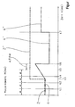
- the single figure shows a flowchart for an intervention in the engine control by means of a alive-counter signal.
- the electronic transmission control device which monitors the proper operation of the transmission with the aid of the above-mentioned sensors, transmits a function signal indicating the proper functioning of the transmission to the engine control system at regular time intervals ⁇ t. As can be seen from the solid vertical lines in the drawing, such a function signal is generated at times t 1 , t 2 and t 4 .
- the motor controller reacts in such a way that it is lowered from the time t 6, the actual torque 4 to a predetermined lower value 4 'and held for a predetermined transition period t 6 to t 7 .
Landscapes
- Engineering & Computer Science (AREA)
- General Engineering & Computer Science (AREA)
- Mechanical Engineering (AREA)
- Control Of Transmission Device (AREA)
- Control Of Vehicle Engines Or Engines For Specific Uses (AREA)
Applications Claiming Priority (2)
| Application Number | Priority Date | Filing Date | Title |
|---|---|---|---|
| DE102006054253A DE102006054253A1 (de) | 2006-11-17 | 2006-11-17 | Verfahren zur Notbetätigung eines automatisierten Fahrzeug-Doppelkupplungsgetriebes |
| PCT/EP2007/061845 WO2008058857A1 (de) | 2006-11-17 | 2007-11-05 | Verfahren zur notbetätigung eines automatisierten fahrzeug-doppelkupplungsgetriebes |
Publications (2)
| Publication Number | Publication Date |
|---|---|
| EP2079943A1 EP2079943A1 (de) | 2009-07-22 |
| EP2079943B1 true EP2079943B1 (de) | 2010-03-10 |
Family
ID=39045045
Family Applications (1)
| Application Number | Title | Priority Date | Filing Date |
|---|---|---|---|
| EP07822174A Not-in-force EP2079943B1 (de) | 2006-11-17 | 2007-11-05 | Verfahren zur notbetätigung eines automatisierten fahrzeug-doppelkupplungsgetriebes |
Country Status (6)
| Country | Link |
|---|---|
| US (1) | US8086381B2 (OSRAM) |
| EP (1) | EP2079943B1 (OSRAM) |
| JP (1) | JP2010510448A (OSRAM) |
| AT (1) | ATE460610T1 (OSRAM) |
| DE (2) | DE102006054253A1 (OSRAM) |
| WO (1) | WO2008058857A1 (OSRAM) |
Cited By (1)
| Publication number | Priority date | Publication date | Assignee | Title |
|---|---|---|---|---|
| CN102235491A (zh) * | 2010-04-26 | 2011-11-09 | 通用汽车环球科技运作公司 | 用于双离合变速器的换档排序系统 |
Families Citing this family (10)
| Publication number | Priority date | Publication date | Assignee | Title |
|---|---|---|---|---|
| JP5368253B2 (ja) * | 2008-10-30 | 2013-12-18 | ヤマハ発動機株式会社 | ツインクラッチ式の変速装置およびそれを備えた車両 |
| DE112011100582B4 (de) * | 2010-02-18 | 2022-02-24 | Schaeffler Technologies AG & Co. KG | Smart Aktor,Verfahren und Steuerungssystem zur Betätigung einer Kupplung |
| EP2653753B1 (en) * | 2010-12-15 | 2019-03-27 | Yamaha Hatsudoki Kabushiki Kaisha | Control device for dual clutch transmission and control method for dual clutch transmission |
| EP2653754B1 (en) * | 2010-12-15 | 2019-07-17 | Yamaha Hatsudoki Kabushiki Kaisha | Control device for dual clutch transmission and control method for dual clutch transmission |
| DE102012003328A1 (de) * | 2012-02-15 | 2013-08-22 | Getrag Getriebe- Und Zahnradfabrik Hermann Hagenmeyer Gmbh & Cie Kg | Verfahren und Steuergerät für eine Antriebsstrang-Komponente |
| WO2013138942A1 (en) | 2012-03-23 | 2013-09-26 | Pacific Rim Engineered Products (1987) Ltd. | Gear engagement mechanism for transmissions and related methods |
| CA2866935A1 (en) | 2012-03-23 | 2013-09-26 | Pacific Rim Engineered Products (1987) Ltd. | Dual clutch type power transmission with alternative torque transmission path providing alternative ratios |
| DE102013202707B4 (de) * | 2013-02-20 | 2024-10-02 | Zf Friedrichshafen Ag | Verfahren zum Betreiben einer Getriebevorrichtung, insbesondere eines 9-Gang-Getriebes |
| JP2015077861A (ja) * | 2013-10-16 | 2015-04-23 | いすゞ自動車株式会社 | ハイブリッドシステム、ハイブリッド車両及びハイブリッド車両の制御方法 |
| JP6309987B2 (ja) * | 2016-02-29 | 2018-04-11 | 本田技研工業株式会社 | 自動変速機及び自動変速機の制御方法 |
Family Cites Families (18)
| Publication number | Priority date | Publication date | Assignee | Title |
|---|---|---|---|---|
| EP0354006B1 (en) * | 1988-08-02 | 1995-01-25 | Toyota Jidosha Kabushiki Kaisha | Hydraulic control device for automatic transmission for vehicle having two parallel input clutches |
| JPH0487086U (OSRAM) * | 1990-11-30 | 1992-07-29 | ||
| US5527233A (en) * | 1993-04-26 | 1996-06-18 | Toyota Jidosha Kabushiki Kaisha | Hydraulic control apparatus for controlling an engaging state of a lock-up clutch of an automatic transmission |
| US5493928A (en) * | 1994-10-14 | 1996-02-27 | Caterpillar Inc. | Transmission control default operation |
| US6463821B1 (en) * | 2001-06-29 | 2002-10-15 | Daimlerchrysler Corporation | Method of controlling a transmission having a dual clutch system |
| DE10390917D2 (de) * | 2002-03-07 | 2005-03-03 | Luk Lamellen & Kupplungsbau | Doppelkupplungsgetriebe und Verfahren zum Steuern von wenigstens zwei Kupplungen bei Doppelkupplungsgetriebe eines Fahrzeuges |
| US7153234B2 (en) * | 2002-03-07 | 2006-12-26 | Luk Lamellen Und Kupplungsbau Beteiligungs Kg | Twin-clutch gearbox and method for controlling at least two clutches in a twin-clutch gearbox of a motor vehicle |
| DE10338355A1 (de) | 2003-08-21 | 2005-03-17 | Bayerische Motoren Werke Ag | Doppelkupplungsgetriebe mit Zustandshaltefunktion |
| EP1519082B1 (de) * | 2003-09-29 | 2007-09-12 | BorgWarner Inc. | Ansteuereinrichtung für hydraulisch betätigbare Kupplungen sowie Verfahren zur Ansteuerung von hydraulisch betätigbarer Kupplungen |
| US6953417B2 (en) * | 2003-11-17 | 2005-10-11 | Borgwarner Inc. | Method for controlling a dual clutch transmission |
| JP2005291395A (ja) * | 2004-03-31 | 2005-10-20 | Jatco Ltd | 車両用ベルト式無段変速機の油圧制御装置 |
| DE102004018962B3 (de) * | 2004-04-14 | 2005-10-06 | Getrag Getriebe- Und Zahnradfabrik Hermann Hagenmeyer Gmbh & Cie Kg | Hydraulikkreis und Verfahren zum Steuern desselben |
| DE102004033362B4 (de) * | 2004-07-02 | 2007-05-16 | Getrag Getriebe Zahnrad | Hydraulikkreis für ein Doppelkupplungsgetriebe |
| JP2006132574A (ja) * | 2004-11-02 | 2006-05-25 | Nissan Motor Co Ltd | ツインクラッチ式マニュアルトランスミッションのフェール時変速制御装置 |
| EP1767825B1 (de) * | 2005-09-22 | 2011-04-13 | Getrag Ford Transmissions GmbH | Hydraulische Steuerungsvorrichtung für ein automatisiertes Doppelkupplungsgetriebe |
| DE112007000453A5 (de) * | 2006-03-08 | 2008-11-27 | Luk Lamellen Und Kupplungsbau Beteiligungs Kg | Verfahren und Vorrichtung zum Steuern des Betriebs eines Parallelschaltgetriebes |
| WO2009006867A2 (de) * | 2007-07-09 | 2009-01-15 | Luk Lamellen Und Kupplungsbau Beteiligungs Kg | Antriebseinheit für ein kraftfahrzeug |
| DE102007063212B4 (de) * | 2007-12-20 | 2010-02-04 | Getrag Getriebe- Und Zahnradfabrik Hermann Hagenmeyer Gmbh & Cie Kg | Aktuatoranordnung für einen Kraftfahrzeugantriebsstrang sowie Verfahren zum Betreiben einer Aktuatoranordnung |
-
2006
- 2006-11-17 DE DE102006054253A patent/DE102006054253A1/de not_active Withdrawn
-
2007
- 2007-11-05 WO PCT/EP2007/061845 patent/WO2008058857A1/de not_active Ceased
- 2007-11-05 DE DE502007003103T patent/DE502007003103D1/de active Active
- 2007-11-05 US US12/513,932 patent/US8086381B2/en not_active Expired - Fee Related
- 2007-11-05 JP JP2009536697A patent/JP2010510448A/ja not_active Ceased
- 2007-11-05 AT AT07822174T patent/ATE460610T1/de active
- 2007-11-05 EP EP07822174A patent/EP2079943B1/de not_active Not-in-force
Cited By (2)
| Publication number | Priority date | Publication date | Assignee | Title |
|---|---|---|---|---|
| CN102235491A (zh) * | 2010-04-26 | 2011-11-09 | 通用汽车环球科技运作公司 | 用于双离合变速器的换档排序系统 |
| CN102235491B (zh) * | 2010-04-26 | 2015-04-22 | 通用汽车环球科技运作公司 | 用于双离合变速器的换档排序系统 |
Also Published As
| Publication number | Publication date |
|---|---|
| WO2008058857A1 (de) | 2008-05-22 |
| US8086381B2 (en) | 2011-12-27 |
| EP2079943A1 (de) | 2009-07-22 |
| DE102006054253A1 (de) | 2008-05-21 |
| JP2010510448A (ja) | 2010-04-02 |
| DE502007003103D1 (de) | 2010-04-22 |
| US20100042302A1 (en) | 2010-02-18 |
| ATE460610T1 (de) | 2010-03-15 |
Similar Documents
| Publication | Publication Date | Title |
|---|---|---|
| EP2079943B1 (de) | Verfahren zur notbetätigung eines automatisierten fahrzeug-doppelkupplungsgetriebes | |
| EP2376815B1 (de) | Verfahren zum betreiben einer getriebevorrichtung eines fahrzeugantriebsstranges | |
| EP2417378B1 (de) | Verfahren zum betreiben eines fahrzeugantriebsstranges | |
| EP1950463B1 (de) | Hydraulische Steuerungsvorrichtung für ein automatisiertes Doppelkupplungsgetriebe | |
| DE10320280A1 (de) | Verfahren und Vorrichtung zum Betrieb insbesondere eines automatischen bzw. automatisierten Getriebes mit Parksperre bzw. Wegrollsicherung | |
| DE19815260A1 (de) | Kraftfahrzeug | |
| WO2004036079A9 (de) | Verfahren und system zum steuern wenigstens eines aktors im antriebsstrang eines fahrzeuges | |
| EP0759514A2 (de) | Steuerung einer automatischen Kupplung in Abhängigkeit von Bremswirkung | |
| EP2173594B1 (de) | Verfahren zum schalten eines stufengetriebegangs eines kraftfahrzeugs in abhängigkeit von der antriebswellendrehzahl | |
| EP2087261B1 (de) | Verfahren zum betreiben eines kraftfahrzeugs | |
| WO2009030219A2 (de) | Verfahren zur steuerung eines doppelkupplungsgetriebes | |
| EP1767825B1 (de) | Hydraulische Steuerungsvorrichtung für ein automatisiertes Doppelkupplungsgetriebe | |
| EP1994311A1 (de) | Verfahren und vorrichtung zum steuern des betriebs eines parallelschaltgetriebes | |
| EP2739883B1 (de) | Verfahren und steuergerät für eine antriebsstrang-komponente | |
| DE10313483A1 (de) | Verfahren zur Übersetzungs- bzw. Gangüberwachung für ein Automatgetriebe oder ein automatisiertes Schaltgetriebe | |
| EP0628442B1 (de) | Anordnung zur Betätigung einer Reibungskupplung eines Kraftfahrzeugs | |
| EP1269044B1 (de) | Verfahren zur früherkennung von störfällen beim betrieb automatischer oder automatisierter getriebe | |
| EP3441647B1 (de) | Verfahren zum schutz vor einer überlastung einer synchronisiervorrichtung | |
| DE10157943B4 (de) | Verfahren zum Ansteuern eines Antriebssystems, welches ein Antriebsaggregat sowie eine automatisierte Getriebeanordnung aufweist | |
| EP1165340B1 (de) | Verfahren zum steuern eines kraftfahrzeugantriebs und danach gesteuerter kraftfahrzeugantrieb | |
| DE102012201145B4 (de) | Verfahren zum Überwachen eines Notlaufzustandes bei einem Getriebe | |
| DE10229317A1 (de) | Verfahren zum Bringen eines Antriebsmoments eines rollenden Fahrzeugs in einen zur Drehmomentübertragung zwischen einem Antriebsaggregat und einer Getriebeanordnung über eine Kupplungsanordnung bereiten Zustand | |
| EP0928379A1 (de) | Automatisch gesteuerte kupplung | |
| DE19815258A1 (de) | Kraftfahrzeug mit einer automatisierten Kupplung | |
| DE102005015159B4 (de) | Verhindern einer ungewollten Fahrzeugbewegung |
Legal Events
| Date | Code | Title | Description |
|---|---|---|---|
| PUAI | Public reference made under article 153(3) epc to a published international application that has entered the european phase |
Free format text: ORIGINAL CODE: 0009012 |
|
| 17P | Request for examination filed |
Effective date: 20090504 |
|
| AK | Designated contracting states |
Kind code of ref document: A1 Designated state(s): AT BE BG CH CY CZ DE DK EE ES FI FR GB GR HU IE IS IT LI LT LU LV MC MT NL PL PT RO SE SI SK TR |
|
| GRAP | Despatch of communication of intention to grant a patent |
Free format text: ORIGINAL CODE: EPIDOSNIGR1 |
|
| DAX | Request for extension of the european patent (deleted) | ||
| GRAS | Grant fee paid |
Free format text: ORIGINAL CODE: EPIDOSNIGR3 |
|
| GRAA | (expected) grant |
Free format text: ORIGINAL CODE: 0009210 |
|
| AK | Designated contracting states |
Kind code of ref document: B1 Designated state(s): AT BE BG CH CY CZ DE DK EE ES FI FR GB GR HU IE IS IT LI LT LU LV MC MT NL PL PT RO SE SI SK TR |
|
| REG | Reference to a national code |
Ref country code: GB Ref legal event code: FG4D Free format text: NOT ENGLISH |
|
| REG | Reference to a national code |
Ref country code: CH Ref legal event code: EP |
|
| REG | Reference to a national code |
Ref country code: IE Ref legal event code: FG4D |
|
| REF | Corresponds to: |
Ref document number: 502007003103 Country of ref document: DE Date of ref document: 20100422 Kind code of ref document: P |
|
| REG | Reference to a national code |
Ref country code: NL Ref legal event code: VDEP Effective date: 20100310 |
|
| PG25 | Lapsed in a contracting state [announced via postgrant information from national office to epo] |
Ref country code: LT Free format text: LAPSE BECAUSE OF FAILURE TO SUBMIT A TRANSLATION OF THE DESCRIPTION OR TO PAY THE FEE WITHIN THE PRESCRIBED TIME-LIMIT Effective date: 20100310 |
|
| LTIE | Lt: invalidation of european patent or patent extension |
Effective date: 20100310 |
|
| PG25 | Lapsed in a contracting state [announced via postgrant information from national office to epo] |
Ref country code: PL Free format text: LAPSE BECAUSE OF FAILURE TO SUBMIT A TRANSLATION OF THE DESCRIPTION OR TO PAY THE FEE WITHIN THE PRESCRIBED TIME-LIMIT Effective date: 20100310 Ref country code: SI Free format text: LAPSE BECAUSE OF FAILURE TO SUBMIT A TRANSLATION OF THE DESCRIPTION OR TO PAY THE FEE WITHIN THE PRESCRIBED TIME-LIMIT Effective date: 20100310 Ref country code: FI Free format text: LAPSE BECAUSE OF FAILURE TO SUBMIT A TRANSLATION OF THE DESCRIPTION OR TO PAY THE FEE WITHIN THE PRESCRIBED TIME-LIMIT Effective date: 20100310 Ref country code: LV Free format text: LAPSE BECAUSE OF FAILURE TO SUBMIT A TRANSLATION OF THE DESCRIPTION OR TO PAY THE FEE WITHIN THE PRESCRIBED TIME-LIMIT Effective date: 20100310 |
|
| REG | Reference to a national code |
Ref country code: IE Ref legal event code: FD4D |
|
| PG25 | Lapsed in a contracting state [announced via postgrant information from national office to epo] |
Ref country code: GR Free format text: LAPSE BECAUSE OF FAILURE TO SUBMIT A TRANSLATION OF THE DESCRIPTION OR TO PAY THE FEE WITHIN THE PRESCRIBED TIME-LIMIT Effective date: 20100611 Ref country code: NL Free format text: LAPSE BECAUSE OF FAILURE TO SUBMIT A TRANSLATION OF THE DESCRIPTION OR TO PAY THE FEE WITHIN THE PRESCRIBED TIME-LIMIT Effective date: 20100310 Ref country code: RO Free format text: LAPSE BECAUSE OF FAILURE TO SUBMIT A TRANSLATION OF THE DESCRIPTION OR TO PAY THE FEE WITHIN THE PRESCRIBED TIME-LIMIT Effective date: 20100310 Ref country code: SE Free format text: LAPSE BECAUSE OF FAILURE TO SUBMIT A TRANSLATION OF THE DESCRIPTION OR TO PAY THE FEE WITHIN THE PRESCRIBED TIME-LIMIT Effective date: 20100310 Ref country code: CY Free format text: LAPSE BECAUSE OF FAILURE TO SUBMIT A TRANSLATION OF THE DESCRIPTION OR TO PAY THE FEE WITHIN THE PRESCRIBED TIME-LIMIT Effective date: 20100310 Ref country code: EE Free format text: LAPSE BECAUSE OF FAILURE TO SUBMIT A TRANSLATION OF THE DESCRIPTION OR TO PAY THE FEE WITHIN THE PRESCRIBED TIME-LIMIT Effective date: 20100310 Ref country code: ES Free format text: LAPSE BECAUSE OF FAILURE TO SUBMIT A TRANSLATION OF THE DESCRIPTION OR TO PAY THE FEE WITHIN THE PRESCRIBED TIME-LIMIT Effective date: 20100621 |
|
| PG25 | Lapsed in a contracting state [announced via postgrant information from national office to epo] |
Ref country code: BG Free format text: LAPSE BECAUSE OF FAILURE TO SUBMIT A TRANSLATION OF THE DESCRIPTION OR TO PAY THE FEE WITHIN THE PRESCRIBED TIME-LIMIT Effective date: 20100610 Ref country code: CZ Free format text: LAPSE BECAUSE OF FAILURE TO SUBMIT A TRANSLATION OF THE DESCRIPTION OR TO PAY THE FEE WITHIN THE PRESCRIBED TIME-LIMIT Effective date: 20100310 Ref country code: IS Free format text: LAPSE BECAUSE OF FAILURE TO SUBMIT A TRANSLATION OF THE DESCRIPTION OR TO PAY THE FEE WITHIN THE PRESCRIBED TIME-LIMIT Effective date: 20100710 Ref country code: SK Free format text: LAPSE BECAUSE OF FAILURE TO SUBMIT A TRANSLATION OF THE DESCRIPTION OR TO PAY THE FEE WITHIN THE PRESCRIBED TIME-LIMIT Effective date: 20100310 |
|
| PLBE | No opposition filed within time limit |
Free format text: ORIGINAL CODE: 0009261 |
|
| STAA | Information on the status of an ep patent application or granted ep patent |
Free format text: STATUS: NO OPPOSITION FILED WITHIN TIME LIMIT |
|
| PG25 | Lapsed in a contracting state [announced via postgrant information from national office to epo] |
Ref country code: DK Free format text: LAPSE BECAUSE OF FAILURE TO SUBMIT A TRANSLATION OF THE DESCRIPTION OR TO PAY THE FEE WITHIN THE PRESCRIBED TIME-LIMIT Effective date: 20100310 Ref country code: IE Free format text: LAPSE BECAUSE OF FAILURE TO SUBMIT A TRANSLATION OF THE DESCRIPTION OR TO PAY THE FEE WITHIN THE PRESCRIBED TIME-LIMIT Effective date: 20100310 Ref country code: PT Free format text: LAPSE BECAUSE OF FAILURE TO SUBMIT A TRANSLATION OF THE DESCRIPTION OR TO PAY THE FEE WITHIN THE PRESCRIBED TIME-LIMIT Effective date: 20100712 |
|
| 26N | No opposition filed |
Effective date: 20101213 |
|
| PG25 | Lapsed in a contracting state [announced via postgrant information from national office to epo] |
Ref country code: IT Free format text: LAPSE BECAUSE OF FAILURE TO SUBMIT A TRANSLATION OF THE DESCRIPTION OR TO PAY THE FEE WITHIN THE PRESCRIBED TIME-LIMIT Effective date: 20100310 |
|
| BERE | Be: lapsed |
Owner name: ZF FRIEDRICHSHAFEN A.G. Effective date: 20101130 |
|
| PG25 | Lapsed in a contracting state [announced via postgrant information from national office to epo] |
Ref country code: MC Free format text: LAPSE BECAUSE OF NON-PAYMENT OF DUE FEES Effective date: 20101130 |
|
| PG25 | Lapsed in a contracting state [announced via postgrant information from national office to epo] |
Ref country code: BE Free format text: LAPSE BECAUSE OF NON-PAYMENT OF DUE FEES Effective date: 20101130 |
|
| PG25 | Lapsed in a contracting state [announced via postgrant information from national office to epo] |
Ref country code: MT Free format text: LAPSE BECAUSE OF FAILURE TO SUBMIT A TRANSLATION OF THE DESCRIPTION OR TO PAY THE FEE WITHIN THE PRESCRIBED TIME-LIMIT Effective date: 20100310 |
|
| PGFP | Annual fee paid to national office [announced via postgrant information from national office to epo] |
Ref country code: FR Payment date: 20111118 Year of fee payment: 5 |
|
| REG | Reference to a national code |
Ref country code: CH Ref legal event code: PL |
|
| PG25 | Lapsed in a contracting state [announced via postgrant information from national office to epo] |
Ref country code: LI Free format text: LAPSE BECAUSE OF NON-PAYMENT OF DUE FEES Effective date: 20111130 Ref country code: CH Free format text: LAPSE BECAUSE OF NON-PAYMENT OF DUE FEES Effective date: 20111130 |
|
| PG25 | Lapsed in a contracting state [announced via postgrant information from national office to epo] |
Ref country code: HU Free format text: LAPSE BECAUSE OF FAILURE TO SUBMIT A TRANSLATION OF THE DESCRIPTION OR TO PAY THE FEE WITHIN THE PRESCRIBED TIME-LIMIT Effective date: 20100911 Ref country code: LU Free format text: LAPSE BECAUSE OF NON-PAYMENT OF DUE FEES Effective date: 20101105 |
|
| PG25 | Lapsed in a contracting state [announced via postgrant information from national office to epo] |
Ref country code: TR Free format text: LAPSE BECAUSE OF FAILURE TO SUBMIT A TRANSLATION OF THE DESCRIPTION OR TO PAY THE FEE WITHIN THE PRESCRIBED TIME-LIMIT Effective date: 20100310 |
|
| GBPC | Gb: european patent ceased through non-payment of renewal fee |
Effective date: 20121105 |
|
| REG | Reference to a national code |
Ref country code: FR Ref legal event code: ST Effective date: 20130731 |
|
| PG25 | Lapsed in a contracting state [announced via postgrant information from national office to epo] |
Ref country code: GB Free format text: LAPSE BECAUSE OF NON-PAYMENT OF DUE FEES Effective date: 20121105 Ref country code: FR Free format text: LAPSE BECAUSE OF NON-PAYMENT OF DUE FEES Effective date: 20121130 |
|
| REG | Reference to a national code |
Ref country code: AT Ref legal event code: MM01 Ref document number: 460610 Country of ref document: AT Kind code of ref document: T Effective date: 20121130 |
|
| PG25 | Lapsed in a contracting state [announced via postgrant information from national office to epo] |
Ref country code: AT Free format text: LAPSE BECAUSE OF NON-PAYMENT OF DUE FEES Effective date: 20121130 |
|
| PGFP | Annual fee paid to national office [announced via postgrant information from national office to epo] |
Ref country code: DE Payment date: 20161101 Year of fee payment: 10 |
|
| REG | Reference to a national code |
Ref country code: DE Ref legal event code: R119 Ref document number: 502007003103 Country of ref document: DE |
|
| PG25 | Lapsed in a contracting state [announced via postgrant information from national office to epo] |
Ref country code: DE Free format text: LAPSE BECAUSE OF NON-PAYMENT OF DUE FEES Effective date: 20180602 |