EP2078485A2 - Staubsauger mit einem Raum zur Aufnahme eines Motorgebläses - Google Patents
Staubsauger mit einem Raum zur Aufnahme eines Motorgebläses Download PDFInfo
- Publication number
- EP2078485A2 EP2078485A2 EP08021513A EP08021513A EP2078485A2 EP 2078485 A2 EP2078485 A2 EP 2078485A2 EP 08021513 A EP08021513 A EP 08021513A EP 08021513 A EP08021513 A EP 08021513A EP 2078485 A2 EP2078485 A2 EP 2078485A2
- Authority
- EP
- European Patent Office
- Prior art keywords
- vacuum cleaner
- housing
- wall portion
- wall
- housing parts
- Prior art date
- Legal status (The legal status is an assumption and is not a legal conclusion. Google has not performed a legal analysis and makes no representation as to the accuracy of the status listed.)
- Granted
Links
- 230000007423 decrease Effects 0.000 claims description 4
- 239000004033 plastic Substances 0.000 claims description 3
- 230000003247 decreasing effect Effects 0.000 claims description 2
- 239000000428 dust Substances 0.000 description 4
- 238000007789 sealing Methods 0.000 description 4
- 238000004519 manufacturing process Methods 0.000 description 3
- 238000000034 method Methods 0.000 description 3
- 230000032683 aging Effects 0.000 description 1
- 238000004891 communication Methods 0.000 description 1
- 238000011161 development Methods 0.000 description 1
- 230000018109 developmental process Effects 0.000 description 1
- 230000000694 effects Effects 0.000 description 1
- 238000002347 injection Methods 0.000 description 1
- 239000007924 injection Substances 0.000 description 1
- 238000009434 installation Methods 0.000 description 1
- 230000002093 peripheral effect Effects 0.000 description 1
Images


Classifications
-
- A—HUMAN NECESSITIES
- A47—FURNITURE; DOMESTIC ARTICLES OR APPLIANCES; COFFEE MILLS; SPICE MILLS; SUCTION CLEANERS IN GENERAL
- A47L—DOMESTIC WASHING OR CLEANING; SUCTION CLEANERS IN GENERAL
- A47L9/00—Details or accessories of suction cleaners, e.g. mechanical means for controlling the suction or for effecting pulsating action; Storing devices specially adapted to suction cleaners or parts thereof; Carrying-vehicles specially adapted for suction cleaners
- A47L9/22—Mountings for motor fan assemblies
-
- A—HUMAN NECESSITIES
- A47—FURNITURE; DOMESTIC ARTICLES OR APPLIANCES; COFFEE MILLS; SPICE MILLS; SUCTION CLEANERS IN GENERAL
- A47L—DOMESTIC WASHING OR CLEANING; SUCTION CLEANERS IN GENERAL
- A47L5/00—Structural features of suction cleaners
- A47L5/12—Structural features of suction cleaners with power-driven air-pumps or air-compressors, e.g. driven by motor vehicle engine vacuum
- A47L5/22—Structural features of suction cleaners with power-driven air-pumps or air-compressors, e.g. driven by motor vehicle engine vacuum with rotary fans
- A47L5/36—Suction cleaners with hose between nozzle and casing; Suction cleaners for fixing on staircases; Suction cleaners for carrying on the back
- A47L5/362—Suction cleaners with hose between nozzle and casing; Suction cleaners for fixing on staircases; Suction cleaners for carrying on the back of the horizontal type, e.g. canister or sledge type
-
- A—HUMAN NECESSITIES
- A47—FURNITURE; DOMESTIC ARTICLES OR APPLIANCES; COFFEE MILLS; SPICE MILLS; SUCTION CLEANERS IN GENERAL
- A47L—DOMESTIC WASHING OR CLEANING; SUCTION CLEANERS IN GENERAL
- A47L9/00—Details or accessories of suction cleaners, e.g. mechanical means for controlling the suction or for effecting pulsating action; Storing devices specially adapted to suction cleaners or parts thereof; Carrying-vehicles specially adapted for suction cleaners
Definitions
- the invention relates to a vacuum cleaner with a housing, comprising two housing parts which, after assembly, enclose a space for accommodating a motor blower, which includes a substantially extending in the joining direction wall area.
- Such a vacuum cleaner is for example from the DE 196 16 156 C1 known.
- the space that receives the motor fan is usually equipped with a first opening, which is associated with the suction side of the fan. To avoid Saugkraftmaschinee, the opening is usually sealed against the suction port of the blower.
- a second opening in the engine fan room serves to blow the air generated by the blower into the environment of the vacuum cleaner.
- an exhaust filter can be arranged.
- the fan In order for the fan to be placed in the engine fan room during the assembly process, it must consist of at least two parts. The interface between these parts must be hermetically sealed after assembly, so that no exhaust air escapes at undesirable points to the outside and thus bypasses the exhaust filter.
- the invention thus raises the problem of disclosing a vacuum cleaner of the type mentioned, in which it is possible to dispense with a seal in the region of the motor fan room and consequently the production is inexpensive.
- the wall portion is formed of two wall portions having a circumferentially closed contour and overlap in the assembled state of the housing parts at their edge regions with interference fit and without interposition of a seal, wherein on each of the housing parts a wall section is arranged. It creates an easy built, inexpensive, easy to produce and pressure-tight connection of the two wall sections of the engine fan room. By dispensing with elastic parts, an aging-related decrease in the sealing effect is avoided.
- the wall sections have a circular or oval cross-section.
- one of the wall sections is designed such that the cross-sectional area which it encloses increases in the direction of the edge assigned to the overlapping region.
- the enlargement of the cross-sectional area is achieved in a simple and expedient manner either by virtue of the fact that the wall section is frusto-conical or by the thickness of the wall section decreasing in the direction of the edge assigned to the overlapping area.
- a further simplification in the joining of the two housing parts is achieved in that the other wall portion is formed such that reduces its outer periphery in the direction of the overlap region associated edge. The conical connection created in this way produces a particularly good sealing seat.
- the housing part can be made in one piece with the wall portion made of plastic. As a result, both the production and the assembly of the housing parts is simplified.
- the lead-through region of a fan motor connection cable is designed as a cable receiver which can be inserted into a recess of a wall section.
- the area where the cable passes through the cable receptacle can then be sealed in a pre-assembly step.
- the two housing parts can be joined together.
- the vacuum cleaner is designed as a vacuum cleaner
- the housing parts are designed as a lower housing part and upper housing part and when the joining direction extends perpendicular to the main extension direction of the housing base or perpendicular to the driving plane of the vacuum cleaner.
- the suction side of the motor fan may be directed to the upper housing part.
- the air outlet for the engine fan can be arranged in the upper housing part.
- FIG. 2 is an exploded view of the upper housing part 1 and the lower housing part 2 of an in FIG. 1 fully shown vacuum cleaner 100 shown prior to their assembly.
- the FIG. 2 also shows an enclosed by these two parts 1 and 2 engine fan 3.
- the housing parts 1 and 2 form after assembly a dust collection chamber 4, in which a not shown in the drawings dust bag can be inserted.
- the dust collecting chamber 4 is connected via a suction port 5 with the suction side of the engine fan 3 in flow communication.
- the motor fan 3 itself is mounted between the two housing parts 1 and 2 in an upright position, that is, the suction opening 6 points upward to the upper housing part 1, whereas, on the other hand, the exhaust openings 7 of the blower pot 8 are directed downward.
- Over rubber buffer 9 in the lower area and a peripheral seal (not shown) around the suction opening 6 in the upper area the fan 3 is held within a motor fan room 10, which is described below with reference to the drawings 2 and 3.
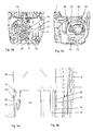
- FIGS. 3a and b shows the interior view of the two housing parts 1 and 2, in which the space for receiving the engine fan 3 is clearly visible. It is cylindrical, with a circular or oval wall portion and two top surfaces 11 and 12. The lower deck surface is formed by the bottom 13 of the housing base 2 itself, it is enclosed by a round wall portion 14. In the top surface 11 ribs 15 are arranged to increase the stability, further, two dome 16 for receiving the rubber buffer 9 can be seen. In the in the FIG. 3a right side of the wall portion is a recess 17 (see also FIG. 4a , left there) whose function is explained later.
- the top surface 12 in the upper housing part passes in the center 19 in an intake passage 20, which ends in the intake 5 in the dust collecting space 4.
- the wall sections 14 and 18 are made in one piece with the housing parts 2 and 1 made of plastic.
- the wall portion 18 When joining the two housing parts 1 and 2, the wall portion 18 is slipped over the wall portion 14. Due to their dimensions arises in the in FIG. 4 illustrated final mounting position an interference fit between these two parts.
- the inner diameter of the wall section 18 in the edge region must be smaller than the outer diameter of the wall section 14 at the point 23 against which the edge 22 of the wall section 18 rests.
- they are designed so that a conical connection is produced.
- their wall thickness decreases in the direction of the edge assigned to the overlapping area.
- the conical connection ensures that only by the assembly in mounting direction (see arrow 27 in FIG. 2 ) pressure produced the press fit is produced.
- the wall sections themselves may be frusto-conical.
- FIG. 5 It can be seen that the recess 17 and thus the contour of the wall portion 14 is closed by an inserted connector receptacle 24 before the assembly of the two housing parts 1 and 2.
- the insert closes the recess airtight.
- the plug receptacle 24 is used for airtight passage of connection cables 25 for the device control and the cable drum (both not shown) from the outside of the motor fan room 10 to the fan 3 on the inside.
- the parked on the connector receptacle 24 connector 26 extends in the mounting direction, so that when placing the motor fan 3 in the lower housing part 2 automatically the electrical connection is made.
Landscapes
- Engineering & Computer Science (AREA)
- Mechanical Engineering (AREA)
- Structures Of Non-Positive Displacement Pumps (AREA)
- Electric Suction Cleaners (AREA)
- Electric Vacuum Cleaner (AREA)
Abstract
Description
- Die Erfindung betrifft einen Staubsauger mit einem Gehäuse, umfassend zwei Gehäuseteile, die nach dem Zusammenfügen einen Raum zur Aufnahme eines Motorgebläses einschließen, welcher einen sich im Wesentlichen in Fügerichtung erstreckenden Wandbereich beinhaltet.
- Ein solcher Staubsauger ist beispielsweise aus der
DE 196 16 156 C1 bekannt. - Der Raum der das Motorgebläse aufnimmt, ist in der Regel mit einer ersten Öffnung ausgestattet, die der Saugseite des Gebläses zugeordnet ist. Um Saugkraftverluste zu vermeiden, ist die Öffnung meist gegenüber der Ansaugöffnung des Gebläses abgedichtet. Eine zweite Öffnung im Motorgebläseraum dient zum Ausblasen der vom Gebläse erzeugten Luft in die Umgebung des Staubsaugers. Vor dieser Öffnung kann ein Abluftfilter angeordnet sein. Damit das Gebläse während des Montagevorgangs in dem Motorgebläseraum platziert werden kann, muss dieser aus mindestens zwei Teilen bestehen. Die Schnittstelle zwischen diesen Teilen muss nach dem Zusammenbau luftdicht abgeschlossen sein, damit keine Abluft an unerwünschten Stellen nach außen tritt und so das Abluftfilter umgeht. Es ist deshalb üblich, an den Verbindungsstellen der einzelnen Wandabschnitte Dichtungen vorzusehen, siehe beispielsweise
DE 44 21 215 B4 . Die Montage einer separaten Dichtung ist zeitintensiv und aufwändig. Da sie als biegeschlaffes Teil ausgebildet ist, kann sie nicht definiert von einem Roboter gegriffen und platziert werden; der Montagevorgang kann deshalb nicht automatisiert werden. Das Anspritzen von Dichtungen im Zweikomponenten-Verfahren erfordert hohe Werkzeuginvestitionen und verlängert die Fertigungszeit. Es ist auch schwierig, Anschlusskabel durch den Dichtungsbereich hindurchzuführen. - Der Erfindung stellt sich somit das Problem, einen Staubsauger der eingangs genannten Art zu offenbaren, bei dem im Bereich des Motorgebläseraums auf eine Dichtung verzichtet werden kann und demzufolge die Herstellung preiswert ist.
- Erfindungsgemäß wird dieses Problem durch einen Staubsauger mit den Merkmalen des Patentanspruchs 1 gelöst. Vorteilhafte Ausgestaltungen und Weiterbildungen der Erfindung ergeben sich aus den nachfolgenden Unteransprüchen.
- Die sich aus der Erfindung ergebenden Vorteile werden dadurch erreicht, dass der Wandbereich aus zwei Wandabschnitten gebildet wird, die eine umlaufend geschlossene Kontur aufweisen und sich im zusammengefügten Zustand der Gehäuseteile an ihren Randbereichen mit Presspassung und ohne Zwischenlage einer Dichtung überlappen, wobei an jedem der Gehäuseteile ein Wandabschnitt angeordnet ist. Es entsteht eine einfach aufgebaute, preisgünstige, leicht zu fertigende und druckdichte Verbindung der beiden Wandabschnitte des Motorgebläseraums. Durch den Verzicht auf elastische Teile wird ein alterungsbedingtes Nachlassen der Dichtwirkung vermieden.
- In einer vorteilhaften Ausführungsform besitzen die Wandabschnitte einen kreisförmigen oder ovalen Querschnitt. Hierdurch wird eine große Eigenstabilität erreicht und somit die notwendige Dichtkraft der Presspassung gewährleistet.
- Es ist auch vorteilhaft, wenn einer der Wandabschnitte derart ausgebildet ist, dass sich die Querschnittsfläche, die er einschließt, in Richtung des dem Überlappungsbereich zugeordneten Rands vergrößert. Durch diese Maßnahme wird das Zusammenfügen der beiden Gehäuseteile mit den Wandabschnitten erleichtert. Die Vergrößerung der Querschnittsfläche wird in einfacher und zweckmäßiger Weise entweder dadurch erreicht, dass der Wandabschnitt kegelstumpfförmig ausgebildet ist, oder dadurch, dass die Stärke des Wandabschnitts in Richtung des dem Überlappungsbereich zugeordneten Rands abnimmt. Eine weitere Vereinfachung beim Zusammenfügen der beiden Gehäuseteile wird dadurch erreicht, dass der andere Wandabschnitt derart ausgebildet ist, dass sich sein Außenumfang in Richtung des dem Überlappungsbereich zugeordneten Rands verringert. Durch die auf diese Weise entstehende Kegelverbindung wird ein besonders guter Dichtsitz erzeugt.
- Es kann je ein Wandabschnitt an ein Gehäuseteil angeformt sein, insbesondere kann das Gehäuseteil mit dem Wandabschnitt einstückig aus Kunststoff hergestellt sein. Hierdurch wird sowohl die Herstellung als auch die Montage der Gehäuseteile vereinfacht.
- In einer besonders vorteilhaften Ausführungsform ist der Durchführungsbereich eines Gebläsemotor-Anschlusskabels als in eine Ausnehmung eines Wandabschnitts einsetzbare Kabelaufnahme ausgebildet. Der Bereich, in dem das Kabel durch die Kabelaufnahme geführt wird, kann dann in einem Vormontageschritt abgedichtet werden. Während der eigentlichen Montage braucht dann nur noch die Kabelaufnahme in die Ausnehmung des Wandabschnitts eingeschoben zu werden, anschließend können die beiden Gehäuseteile zusammengefügt werden.
- Wenn der Staubsauger als Bodenstaubsauger ausgebildet ist, ist es zweckmäßig, wenn die Gehäuseteile als Gehäuseunterteil und Gehäuseoberteil ausgebildet sind und wenn sich die Fügerichtung senkrecht zur Hauptausdehnungsrichtung des Gehäuseunterteils bzw. senkrecht zur Fahrebene des Bodenstaubsaugers erstreckt. Dabei kann die Saugseite des Motorgebläses zum Gehäuseoberteil gerichtet sein. Auch der Luftauslass für das Motorgebläse kann im Gehäuseoberteil angeordnet sein.
- Ein Ausführungsbeispiel der Erfindung ist in den Zeichnungen rein schematisch dargestellt und wird nachfolgend näher beschrieben. Es zeigt
- Figur 1
- einen Bodenstaubsauger in perspektivischer Darstellung;
- Figur 2
- Gehäuseteile und das Motorgebläse des Bodenstaubsaugers nach
Figur 1 in Explosionsdarstellung; - Figuren 3a, b
- die Gehäuseteile gemäß
Figur 2 in der Draufsicht von innen; - Figuren 4a, b
- Längsschnitte durch die zusammengefügten Wandabschnitte in den jeweiligen Randbereichen des Staubsaugergehäuses;
- Figur 5
- das Gehäuseunterteil des Bodenstaubsaugers mit eingeschobener Steckeraufnahme.
- In
Figur 2 ist in einer Explosionsdarstellung das Gehäuseoberteil 1 und das Gehäuseunterteil 2 eines inFigur 1 vollständig gezeigten Bodenstaubsaugers 100 vor ihrem Zusammenbau dargestellt. DieFigur 2 zeigt weiterhin ein von diesen beiden Teilen 1 und 2 eingeschlossenes Motorgebläse 3. Die Gehäuseteile 1 und 2 bilden nach dem Zusammenfügen einen Staubsammelraum 4, in welchen ein in den Zeichnungen nicht dargestellter Staubbeutel eingelegt werden kann. Der Staubsammelraum 4 steht über eine Ansaugöffnung 5 mit der Saugseite des Motorgebläses 3 in Strömungsverbindung. Das Motorgebläse 3 selbst ist zwischen den beiden Gehäuseteilen 1 und 2 in aufrechter Position gelagert, das heißt, die Saugöffnung 6 zeigt nach oben zum Gehäuseoberteil 1, wo hingegen die Ausblasöffnungen 7 des Gebläsetopfes 8 nach unten gerichtet sind. Über Gummipuffer 9 im unteren Bereich und eine umlaufende Dichtung (nicht dargestellt) um die Saugöffnung 6 im oberen Bereich wird das Gebläse 3 innerhalb eines Motorgebläseraums 10 gehalten, der unter Bezugnahme auf die Zeichnungen 2 und 3 nachfolgend beschrieben ist. - In den
Figuren 3a und b ist die Innenansicht der beiden Gehäuseteile 1 und 2 gezeigt, in der der Raum zur Aufnahme des Motorgebläses 3 gut erkennbar ist. Er ist zylindrisch ausgebildet, mit einem kreisrunden oder ovalen Wandbereich und zwei Deckflächen 11 und 12. Die untere Deckfläche wird durch den Boden 13 des Gehäuseunterteils 2 selbst gebildet, sie wird von einem runden Wandabschnitt 14 eingeschlossen. In der Deckfläche 11 sind Rippen 15 zur Erhöhung der Stabilität angeordnet, des Weiteren sind zwei Dome 16 zur Aufnahme der Gummipuffer 9 erkennbar. In der in derFigur 3a rechten Seite des Wandabschnitts ist eine Ausnehmung 17 (siehe auchFigur 4a , dort links) angeordnet, deren Funktion später erklärt ist. - An das Gehäuseoberteil 1 ist ebenfalls ein runder Wandabschnitt 18 mit einer umlaufend geschlossenen Kontur angeformt, der zusammen mit dem Wandabschnitt 14 im Gehäuseunterteil 2 den Wandbereich des Motorgebläseraums 10 bildet. Die Deckfläche 12 im Gehäuseoberteil geht im Zentrum 19 in einen Ansaugkanal 20 über, der in der Ansaugöffnung 5 im Staubsammelraum 4 endet. Um den Ansaugkanal 20 herum ist der Luftauslass des Motorgebläseraums 10 in Form von vergitterten Ausblasöffnungen 21 angeordnet. Die Wandabschnitte 14 und 18 sind zusammen mit den Gehäuseteilen 2 und 1 einstückig aus Kunststoff hergestellt.
- Beim Zusammenfügen der beiden Gehäuseteile 1 und 2 wird der Wandabschnitt 18 über den Wandabschnitt 14 gestülpt. Aufgrund ihrer Abmessungen entsteht in der in
Figur 4 dargestellten endgültigen Montageposition eine Presspassung zwischen diesen beiden Teilen. Hierzu muss der Innendurchmesser des Wandabschnitts 18 im Randbereich kleiner sein als der Außendurchmesser des Wandabschnitts 14 an der Stelle 23, an der der Rand 22 des Wandabschnitts 18 anliegt. Um das Übereinanderstülpen der Wandabschnitte 14 und 18 zu erleichtern, sind sie so ausgebildet, dass eine Kegelverbindung erzeugt wird. Hierzu nimmt ihre Wandstärke in Richtung des dem Überlappungsbereich zugeordneten Rands ab. Die Kegelverbindung stellt sicher, dass allein durch den beim Zusammenbau in Montagerichtung (siehe Pfeil 27 inFigur 2 ) erzeugten Druck die Presspassung hergestellt wird. Alternativ zur Verjüngung der Wandstärke können die Wandabschnitte selbst kegelstumpfförmig ausgebildet sein. - In
Figur 5 ist erkennbar, dass die Ausnehmung 17 und damit die Kontur des Wandabschnitts 14 vor dem Zusammenbau der beiden Gehäuseteile 1 und 2 durch eine eingeschobene Steckeraufnahme 24 geschlossen ist. Durch den Einschub wird die Ausnehmung luftdicht abgeschlossen. Die Steckeraufnahme 24 dient zur luftdichten Durchführung von Anschlusskabeln 25 für die Gerätesteuerung und die Kabeltrommel (beide nicht dargestellt) von der Außenseite des Motorgebläseraums 10 zum Gebläse 3 auf der Innenseite. Der an der Steckeraufnahme 24 geparkte Stecker 26 erstreckt sich in Montagerichtung, so dass beim Platzieren des Motorgebläses 3 im Gehäuseunterteil 2 selbsttätig die elektrische Verbindung hergestellt wird.
Claims (15)
- Staubsauger (100) mit einem Gehäuse, umfassend zwei Gehäuseteile (1, 2), die nach dem Zusammenfügen einen Raum (10) zur Aufnahme eines Motorgebläses (3) einschließen, welcher einen sich im Wesentlichen in Fügerichtung erstreckenden Wandbereich beinhaltet,
dadurch gekennzeichnet,
dass der Wandbereich aus zwei Wandabschnitten (14, 18) gebildet wird, die eine umlaufend geschlossene Kontur aufweisen und sich im zusammengefügten Zustand der Gehäuseteile (1, 2) an ihren Randbereichen mit Presspassung und ohne Zwischenlage einer Dichtung überlappen, wobei an jedem der Gehäuseteile (1 bzw. 2) ein Wandabschnitt (18 bzw. 14) angeordnet ist. - Staubsauger (100) nach Anspruch 1,
dadurch gekennzeichnet,
dass die Wandabschnitte (14, 18) einen kreisförmigen oder ovalen Querschnitt besitzen. - Staubsauger (100) nach Anspruch 1 oder 2,
dadurch gekennzeichnet,
dass einer der Wandabschnitte (18) derart ausgebildet ist, dass sich die Querschnittsfläche, die er einschließt, in Richtung des dem Überlappungsbereich zugeordneten Rands (22) vergrößert. - Staubsauger (100) nach Anspruch 3,
dadurch gekennzeichnet,
dass der Wandabschnitt (18) kegelstumpfförmig ausgebildet ist. - Staubsauger (100) nach Anspruch 3,
dadurch gekennzeichnet,
dass die Stärke des Wandabschnitts (18) in Richtung des dem Überlappungsbereich zugeordneten Rands (22) abnimmt. - Staubsauger (100) nach mindestens einem der Ansprüche 3 bis 5,
dadurch gekennzeichnet,
dass der andere Wandabschnitt (14) derart ausgebildet ist, dass sich sein Außenumfang in Richtung des dem Überlappungsbereich (23) zugeordneten Rands verringert. - Staubsauger (100) nach Anspruch 6,
dadurch gekennzeichnet,
dass der Wandabschnitt (14) kegelstumpfförmig ausgebildet ist. - Staubsauger (100) nach Anspruch 6,
dadurch gekennzeichnet,
dass die Stärke des Wandabschnitts (14) in Richtung des dem Überlappungsbereich (23) zugeordneten Rands abnimmt. - Staubsauger (100) nach mindestens einem der vorhergehenden Ansprüche,
dadurch gekennzeichnet,
dass je ein Wandabschnitt (18 bzw. 14) an ein Gehäuseteil (1 bzw. 2) angeformt ist. - Staubsauger (100) nach Anspruch 9,
dadurch gekennzeichnet,
dass das Gehäuseteil (1 bzw. 2) mit dem Wandabschnitt (18 bzw. 14) einstückig aus Kunststoff hergestellt ist. - Staubsauger (100) nach mindestens einem der vorhergehenden Ansprüche,
dadurch gekennzeichnet,
dass der Durchführungsbereich mindestens eines Gebläsemotor-Anschlusskabels (25) als in eine Ausnehmung (17) eines Wandabschnitts (14) einsetzbare Steckeraufnahme (24) ausgebildet ist. - Staubsauger (100) nach Anspruch 11,
dadurch gekennzeichnet,
dass die Steckeraufnahme (24) in die Ausnehmung (17) eines Wandabschnitts (14) dichtend einschiebbar ausgebildet ist. - Bodenstaubsauger (100) nach mindestens einem der vorhergehenden Ansprüche,
dadurch gekennzeichnet,
dass die Gehäuseteile als Gehäuseunterteil (2) und Gehäuseoberteil (1) ausgebildet sind und dass sich die Fügerichtung (27) senkrecht zur Hauptausdehnungsrichtung des Gehäuseunterteils bzw. senkrecht zur Fahrebene des Bodenstaubsaugers erstreckt. - Bodenstaubsauger (100) nach Anspruch 13,
dadurch gekennzeichnet,
dass die Saugöffnung (6) des Motorgebläses (3) zum Gehäuseoberteil (1) gerichtet ist. - Bodenstaubsauger (100) nach Anspruch 14,
dadurch gekennzeichnet,
dass der Luftauslass (21) des Motorgebläseraums (10) im Gehäuseoberteil (1) angeordnet ist.
Applications Claiming Priority (1)
| Application Number | Priority Date | Filing Date | Title |
|---|---|---|---|
| DE200810003350 DE102008003350B4 (de) | 2008-01-08 | 2008-01-08 | Staubsauger mit einem Raum zur Aufnahme eines Motorgebläses |
Publications (3)
| Publication Number | Publication Date |
|---|---|
| EP2078485A2 true EP2078485A2 (de) | 2009-07-15 |
| EP2078485A3 EP2078485A3 (de) | 2011-02-16 |
| EP2078485B1 EP2078485B1 (de) | 2012-10-03 |
Family
ID=40404272
Family Applications (1)
| Application Number | Title | Priority Date | Filing Date |
|---|---|---|---|
| EP20080021513 Active EP2078485B1 (de) | 2008-01-08 | 2008-12-11 | Staubsauger mit einem Raum zur Aufnahme eines Motorgebläses |
Country Status (2)
| Country | Link |
|---|---|
| EP (1) | EP2078485B1 (de) |
| DE (1) | DE102008003350B4 (de) |
Cited By (1)
| Publication number | Priority date | Publication date | Assignee | Title |
|---|---|---|---|---|
| EP2510855A3 (de) * | 2011-04-12 | 2014-08-06 | BSH Bosch und Siemens Hausgeräte GmbH | Motoranordnung für ein elektromotorisch angetriebenes Haushaltsgerät und Reinigungsgerät |
Families Citing this family (1)
| Publication number | Priority date | Publication date | Assignee | Title |
|---|---|---|---|---|
| EP3866658A1 (de) | 2018-10-19 | 2021-08-25 | Alfred Kärcher SE & Co. KG | Saugmaschine mit schallwinkel |
Citations (3)
| Publication number | Priority date | Publication date | Assignee | Title |
|---|---|---|---|---|
| DE19616156C1 (de) | 1996-04-23 | 1997-10-02 | Fakir Werk Gmbh & Co | Staubsauger |
| WO2005016107A1 (de) | 2003-08-11 | 2005-02-24 | BSH Bosch und Siemens Hausgeräte GmbH | Staubsauger mit einer gebläsekapsel |
| DE4421215B4 (de) | 1994-06-17 | 2007-01-18 | Miele & Cie. Kg | Staubsauger mit einer Trennfugendichtung |
Family Cites Families (1)
| Publication number | Priority date | Publication date | Assignee | Title |
|---|---|---|---|---|
| FR2873563B1 (fr) * | 2004-07-29 | 2006-09-22 | Seb Sa | Aspirateur |
-
2008
- 2008-01-08 DE DE200810003350 patent/DE102008003350B4/de active Active
- 2008-12-11 EP EP20080021513 patent/EP2078485B1/de active Active
Patent Citations (3)
| Publication number | Priority date | Publication date | Assignee | Title |
|---|---|---|---|---|
| DE4421215B4 (de) | 1994-06-17 | 2007-01-18 | Miele & Cie. Kg | Staubsauger mit einer Trennfugendichtung |
| DE19616156C1 (de) | 1996-04-23 | 1997-10-02 | Fakir Werk Gmbh & Co | Staubsauger |
| WO2005016107A1 (de) | 2003-08-11 | 2005-02-24 | BSH Bosch und Siemens Hausgeräte GmbH | Staubsauger mit einer gebläsekapsel |
Cited By (1)
| Publication number | Priority date | Publication date | Assignee | Title |
|---|---|---|---|---|
| EP2510855A3 (de) * | 2011-04-12 | 2014-08-06 | BSH Bosch und Siemens Hausgeräte GmbH | Motoranordnung für ein elektromotorisch angetriebenes Haushaltsgerät und Reinigungsgerät |
Also Published As
| Publication number | Publication date |
|---|---|
| DE102008003350A1 (de) | 2009-07-09 |
| EP2078485A3 (de) | 2011-02-16 |
| EP2078485B1 (de) | 2012-10-03 |
| DE102008003350B4 (de) | 2011-05-19 |
Similar Documents
| Publication | Publication Date | Title |
|---|---|---|
| EP1992395B1 (de) | Filter, insbesondere Luftfilter | |
| DE2907503C2 (de) | Rohrverbindung, insbesondere zu einem Ölfiltersieb | |
| DE202015102280U1 (de) | Anordnung mit einer Wanddurchführung für mehrere Kabel und Bausatz | |
| EP2938986A1 (de) | Verfahren zum herstellen eines sensorgehäuses sowie entsprechendes sensorgehäuse | |
| DE102013208108A1 (de) | Flüssigkeitsaufnahmebehälter für eine Vorrichtung zur Bereitstellung von Unterdruck für medizinischeAnwendungen, Verfahren zur Herstellung des Behälters, sowie Vorrichtung | |
| DE29813935U1 (de) | Unlösbare Preßverbindung zwischen einem Fitting und einem Metallrohrende | |
| EP0603741A1 (de) | Kabeltülle | |
| EP2078485B1 (de) | Staubsauger mit einem Raum zur Aufnahme eines Motorgebläses | |
| EP1513721A1 (de) | Verschlussdeckel | |
| EP0537521A1 (de) | Flüssigkeitsfilter | |
| DE10322878B4 (de) | Anordnung zum dichtenden Verbinden zweier rohrförmiger Elemente | |
| WO2007025924A1 (de) | Staubsaugerbeutel mit kunststoffflansch | |
| WO2017076558A1 (de) | Behälter mit versteifungseinrichtung | |
| DE102007052150B4 (de) | Antriebseinheit mit einem Gehäuse, sowie ein Herstellungsverfahren einer solchen | |
| EP0537520A1 (de) | Flüssigkeitsfilter | |
| EP0921927B1 (de) | Verfahren zur herstellung eines dichten kunststoffgehäuses | |
| EP2268181B1 (de) | Staubsauger mit unterdruckventil | |
| EP1678439B1 (de) | Rohrmuffe | |
| DE102007034817A1 (de) | Gedichtetes Kontaktgehäuse für eine elektrische Steckverbindung in einem Fahrzeug | |
| DE19947207A1 (de) | Dichtungselement und Verfahren zur Herstellung | |
| DE10216721B4 (de) | Verbindungssystem für die form-und/oder kraftschlüssige Verbindung zweier Bauteile | |
| DE3102382C2 (de) | ||
| DE3927128C2 (de) | ||
| DE19753049C1 (de) | Geräuschdämpfer für ein Pneumatikaggregat | |
| EP0474017B1 (de) | Pneumatisches Stellelement, insbesondere für Kraftfahrzeuge |
Legal Events
| Date | Code | Title | Description |
|---|---|---|---|
| PUAI | Public reference made under article 153(3) epc to a published international application that has entered the european phase |
Free format text: ORIGINAL CODE: 0009012 |
|
| AK | Designated contracting states |
Kind code of ref document: A2 Designated state(s): AT BE BG CH CY CZ DE DK EE ES FI FR GB GR HR HU IE IS IT LI LT LU LV MC MT NL NO PL PT RO SE SI SK TR |
|
| AX | Request for extension of the european patent |
Extension state: AL BA MK RS |
|
| PUAL | Search report despatched |
Free format text: ORIGINAL CODE: 0009013 |
|
| AK | Designated contracting states |
Kind code of ref document: A3 Designated state(s): AT BE BG CH CY CZ DE DK EE ES FI FR GB GR HR HU IE IS IT LI LT LU LV MC MT NL NO PL PT RO SE SI SK TR |
|
| AX | Request for extension of the european patent |
Extension state: AL BA MK RS |
|
| RIC1 | Information provided on ipc code assigned before grant |
Ipc: A47L 9/00 20060101ALI20110110BHEP Ipc: A47L 5/00 20060101AFI20090317BHEP Ipc: A47L 5/36 20060101ALI20110110BHEP Ipc: A47L 9/22 20060101ALI20110110BHEP |
|
| 17P | Request for examination filed |
Effective date: 20110413 |
|
| AKX | Designation fees paid |
Designated state(s): AT BE BG CH CY CZ DE DK EE ES FI FR GB GR HR HU IE IS IT LI LT LU LV MC MT NL NO PL PT RO SE SI SK TR |
|
| GRAP | Despatch of communication of intention to grant a patent |
Free format text: ORIGINAL CODE: EPIDOSNIGR1 |
|
| RBV | Designated contracting states (corrected) |
Designated state(s): AT BE BG CH CY CZ DK EE ES FI FR GB GR HR HU IE IS IT LI LT LU LV MC MT NL NO PL PT RO SE SI SK TR |
|
| REG | Reference to a national code |
Ref country code: DE Ref legal event code: R108 |
|
| GRAS | Grant fee paid |
Free format text: ORIGINAL CODE: EPIDOSNIGR3 |
|
| GRAA | (expected) grant |
Free format text: ORIGINAL CODE: 0009210 |
|
| AK | Designated contracting states |
Kind code of ref document: B1 Designated state(s): AT BE BG CH CY CZ DK EE ES FI FR GB GR HR HU IE IS IT LI LT LU LV MC MT NL NO PL PT RO SE SI SK TR |
|
| REG | Reference to a national code |
Ref country code: GB Ref legal event code: FG4D Free format text: NOT ENGLISH |
|
| REG | Reference to a national code |
Ref country code: DE Ref legal event code: R108 Effective date: 20120822 |
|
| REG | Reference to a national code |
Ref country code: AT Ref legal event code: REF Ref document number: 577577 Country of ref document: AT Kind code of ref document: T Effective date: 20121015 Ref country code: CH Ref legal event code: EP |
|
| REG | Reference to a national code |
Ref country code: IE Ref legal event code: FG4D Free format text: LANGUAGE OF EP DOCUMENT: GERMAN |
|
| REG | Reference to a national code |
Ref country code: GB Ref legal event code: 746 Effective date: 20121016 |
|
| PG25 | Lapsed in a contracting state [announced via postgrant information from national office to epo] |
Ref country code: SI Free format text: LAPSE BECAUSE OF FAILURE TO SUBMIT A TRANSLATION OF THE DESCRIPTION OR TO PAY THE FEE WITHIN THE PRESCRIBED TIME-LIMIT Effective date: 20121003 |
|
| REG | Reference to a national code |
Ref country code: NL Ref legal event code: VDEP Effective date: 20121003 |
|
| REG | Reference to a national code |
Ref country code: LT Ref legal event code: MG4D |
|
| PG25 | Lapsed in a contracting state [announced via postgrant information from national office to epo] |
Ref country code: LT Free format text: LAPSE BECAUSE OF FAILURE TO SUBMIT A TRANSLATION OF THE DESCRIPTION OR TO PAY THE FEE WITHIN THE PRESCRIBED TIME-LIMIT Effective date: 20121003 Ref country code: ES Free format text: LAPSE BECAUSE OF FAILURE TO SUBMIT A TRANSLATION OF THE DESCRIPTION OR TO PAY THE FEE WITHIN THE PRESCRIBED TIME-LIMIT Effective date: 20130114 Ref country code: FI Free format text: LAPSE BECAUSE OF FAILURE TO SUBMIT A TRANSLATION OF THE DESCRIPTION OR TO PAY THE FEE WITHIN THE PRESCRIBED TIME-LIMIT Effective date: 20121003 Ref country code: SE Free format text: LAPSE BECAUSE OF FAILURE TO SUBMIT A TRANSLATION OF THE DESCRIPTION OR TO PAY THE FEE WITHIN THE PRESCRIBED TIME-LIMIT Effective date: 20121003 Ref country code: HR Free format text: LAPSE BECAUSE OF FAILURE TO SUBMIT A TRANSLATION OF THE DESCRIPTION OR TO PAY THE FEE WITHIN THE PRESCRIBED TIME-LIMIT Effective date: 20121003 Ref country code: NL Free format text: LAPSE BECAUSE OF FAILURE TO SUBMIT A TRANSLATION OF THE DESCRIPTION OR TO PAY THE FEE WITHIN THE PRESCRIBED TIME-LIMIT Effective date: 20121003 Ref country code: NO Free format text: LAPSE BECAUSE OF FAILURE TO SUBMIT A TRANSLATION OF THE DESCRIPTION OR TO PAY THE FEE WITHIN THE PRESCRIBED TIME-LIMIT Effective date: 20130103 Ref country code: IS Free format text: LAPSE BECAUSE OF FAILURE TO SUBMIT A TRANSLATION OF THE DESCRIPTION OR TO PAY THE FEE WITHIN THE PRESCRIBED TIME-LIMIT Effective date: 20130203 |
|
| PG25 | Lapsed in a contracting state [announced via postgrant information from national office to epo] |
Ref country code: PL Free format text: LAPSE BECAUSE OF FAILURE TO SUBMIT A TRANSLATION OF THE DESCRIPTION OR TO PAY THE FEE WITHIN THE PRESCRIBED TIME-LIMIT Effective date: 20121003 Ref country code: LV Free format text: LAPSE BECAUSE OF FAILURE TO SUBMIT A TRANSLATION OF THE DESCRIPTION OR TO PAY THE FEE WITHIN THE PRESCRIBED TIME-LIMIT Effective date: 20121003 Ref country code: GR Free format text: LAPSE BECAUSE OF FAILURE TO SUBMIT A TRANSLATION OF THE DESCRIPTION OR TO PAY THE FEE WITHIN THE PRESCRIBED TIME-LIMIT Effective date: 20130104 Ref country code: PT Free format text: LAPSE BECAUSE OF FAILURE TO SUBMIT A TRANSLATION OF THE DESCRIPTION OR TO PAY THE FEE WITHIN THE PRESCRIBED TIME-LIMIT Effective date: 20130204 |
|
| BERE | Be: lapsed |
Owner name: MIELE & CIE. K.G. Effective date: 20121231 |
|
| PG25 | Lapsed in a contracting state [announced via postgrant information from national office to epo] |
Ref country code: DK Free format text: LAPSE BECAUSE OF FAILURE TO SUBMIT A TRANSLATION OF THE DESCRIPTION OR TO PAY THE FEE WITHIN THE PRESCRIBED TIME-LIMIT Effective date: 20121003 Ref country code: CZ Free format text: LAPSE BECAUSE OF FAILURE TO SUBMIT A TRANSLATION OF THE DESCRIPTION OR TO PAY THE FEE WITHIN THE PRESCRIBED TIME-LIMIT Effective date: 20121003 Ref country code: SK Free format text: LAPSE BECAUSE OF FAILURE TO SUBMIT A TRANSLATION OF THE DESCRIPTION OR TO PAY THE FEE WITHIN THE PRESCRIBED TIME-LIMIT Effective date: 20121003 Ref country code: BG Free format text: LAPSE BECAUSE OF FAILURE TO SUBMIT A TRANSLATION OF THE DESCRIPTION OR TO PAY THE FEE WITHIN THE PRESCRIBED TIME-LIMIT Effective date: 20130103 Ref country code: MC Free format text: LAPSE BECAUSE OF NON-PAYMENT OF DUE FEES Effective date: 20121231 Ref country code: EE Free format text: LAPSE BECAUSE OF FAILURE TO SUBMIT A TRANSLATION OF THE DESCRIPTION OR TO PAY THE FEE WITHIN THE PRESCRIBED TIME-LIMIT Effective date: 20121003 |
|
| REG | Reference to a national code |
Ref country code: CH Ref legal event code: PL |
|
| PLBE | No opposition filed within time limit |
Free format text: ORIGINAL CODE: 0009261 |
|
| STAA | Information on the status of an ep patent application or granted ep patent |
Free format text: STATUS: NO OPPOSITION FILED WITHIN TIME LIMIT |
|
| PG25 | Lapsed in a contracting state [announced via postgrant information from national office to epo] |
Ref country code: RO Free format text: LAPSE BECAUSE OF FAILURE TO SUBMIT A TRANSLATION OF THE DESCRIPTION OR TO PAY THE FEE WITHIN THE PRESCRIBED TIME-LIMIT Effective date: 20121003 |
|
| PGFP | Annual fee paid to national office [announced via postgrant information from national office to epo] |
Ref country code: HU Payment date: 20121206 Year of fee payment: 5 |
|
| 26N | No opposition filed |
Effective date: 20130704 |
|
| REG | Reference to a national code |
Ref country code: IE Ref legal event code: MM4A |
|
| PG25 | Lapsed in a contracting state [announced via postgrant information from national office to epo] |
Ref country code: BE Free format text: LAPSE BECAUSE OF NON-PAYMENT OF DUE FEES Effective date: 20121231 |
|
| REG | Reference to a national code |
Ref country code: HU Ref legal event code: AG4A Ref document number: E016681 Country of ref document: HU |
|
| PG25 | Lapsed in a contracting state [announced via postgrant information from national office to epo] |
Ref country code: IE Free format text: LAPSE BECAUSE OF NON-PAYMENT OF DUE FEES Effective date: 20121211 Ref country code: LI Free format text: LAPSE BECAUSE OF NON-PAYMENT OF DUE FEES Effective date: 20121231 Ref country code: CH Free format text: LAPSE BECAUSE OF NON-PAYMENT OF DUE FEES Effective date: 20121231 |
|
| PG25 | Lapsed in a contracting state [announced via postgrant information from national office to epo] |
Ref country code: CY Free format text: LAPSE BECAUSE OF FAILURE TO SUBMIT A TRANSLATION OF THE DESCRIPTION OR TO PAY THE FEE WITHIN THE PRESCRIBED TIME-LIMIT Effective date: 20121003 Ref country code: MT Free format text: LAPSE BECAUSE OF FAILURE TO SUBMIT A TRANSLATION OF THE DESCRIPTION OR TO PAY THE FEE WITHIN THE PRESCRIBED TIME-LIMIT Effective date: 20121003 |
|
| PG25 | Lapsed in a contracting state [announced via postgrant information from national office to epo] |
Ref country code: TR Free format text: LAPSE BECAUSE OF FAILURE TO SUBMIT A TRANSLATION OF THE DESCRIPTION OR TO PAY THE FEE WITHIN THE PRESCRIBED TIME-LIMIT Effective date: 20121003 |
|
| PG25 | Lapsed in a contracting state [announced via postgrant information from national office to epo] |
Ref country code: LU Free format text: LAPSE BECAUSE OF NON-PAYMENT OF DUE FEES Effective date: 20121211 |
|
| PG25 | Lapsed in a contracting state [announced via postgrant information from national office to epo] |
Ref country code: HU Free format text: LAPSE BECAUSE OF NON-PAYMENT OF DUE FEES Effective date: 20131212 |
|
| REG | Reference to a national code |
Ref country code: AT Ref legal event code: MM01 Ref document number: 577577 Country of ref document: AT Kind code of ref document: T Effective date: 20131211 |
|
| PG25 | Lapsed in a contracting state [announced via postgrant information from national office to epo] |
Ref country code: AT Free format text: LAPSE BECAUSE OF NON-PAYMENT OF DUE FEES Effective date: 20131211 |
|
| REG | Reference to a national code |
Ref country code: FR Ref legal event code: PLFP Year of fee payment: 8 |
|
| REG | Reference to a national code |
Ref country code: FR Ref legal event code: PLFP Year of fee payment: 9 |
|
| REG | Reference to a national code |
Ref country code: FR Ref legal event code: PLFP Year of fee payment: 10 |
|
| P01 | Opt-out of the competence of the unified patent court (upc) registered |
Effective date: 20230529 |
|
| PGFP | Annual fee paid to national office [announced via postgrant information from national office to epo] |
Ref country code: GB Payment date: 20241217 Year of fee payment: 17 |
|
| PGFP | Annual fee paid to national office [announced via postgrant information from national office to epo] |
Ref country code: FR Payment date: 20241227 Year of fee payment: 17 |
|
| PGFP | Annual fee paid to national office [announced via postgrant information from national office to epo] |
Ref country code: IT Payment date: 20241220 Year of fee payment: 17 |