EP2077749B1 - Automated ecg lead impedance measurement integrated into ecg gating circuitry - Google Patents
Automated ecg lead impedance measurement integrated into ecg gating circuitry Download PDFInfo
- Publication number
- EP2077749B1 EP2077749B1 EP07837071A EP07837071A EP2077749B1 EP 2077749 B1 EP2077749 B1 EP 2077749B1 EP 07837071 A EP07837071 A EP 07837071A EP 07837071 A EP07837071 A EP 07837071A EP 2077749 B1 EP2077749 B1 EP 2077749B1
- Authority
- EP
- European Patent Office
- Prior art keywords
- electrode
- impedance
- alternating current
- current generator
- electrodes
- Prior art date
- Legal status (The legal status is an assumption and is not a legal conclusion. Google has not performed a legal analysis and makes no representation as to the accuracy of the status listed.)
- Active
Links
Images


Classifications
-
- A—HUMAN NECESSITIES
- A61—MEDICAL OR VETERINARY SCIENCE; HYGIENE
- A61B—DIAGNOSIS; SURGERY; IDENTIFICATION
- A61B5/00—Measuring for diagnostic purposes; Identification of persons
- A61B5/05—Detecting, measuring or recording for diagnosis by means of electric currents or magnetic fields; Measuring using microwaves or radio waves
- A61B5/053—Measuring electrical impedance or conductance of a portion of the body
-
- A—HUMAN NECESSITIES
- A61—MEDICAL OR VETERINARY SCIENCE; HYGIENE
- A61B—DIAGNOSIS; SURGERY; IDENTIFICATION
- A61B5/00—Measuring for diagnostic purposes; Identification of persons
- A61B5/24—Detecting, measuring or recording bioelectric or biomagnetic signals of the body or parts thereof
- A61B5/25—Bioelectric electrodes therefor
- A61B5/279—Bioelectric electrodes therefor specially adapted for particular uses
- A61B5/28—Bioelectric electrodes therefor specially adapted for particular uses for electrocardiography [ECG]
-
- A—HUMAN NECESSITIES
- A61—MEDICAL OR VETERINARY SCIENCE; HYGIENE
- A61B—DIAGNOSIS; SURGERY; IDENTIFICATION
- A61B5/00—Measuring for diagnostic purposes; Identification of persons
- A61B5/68—Arrangements of detecting, measuring or recording means, e.g. sensors, in relation to patient
- A61B5/6801—Arrangements of detecting, measuring or recording means, e.g. sensors, in relation to patient specially adapted to be attached to or worn on the body surface
- A61B5/6843—Monitoring or controlling sensor contact pressure
-
- A—HUMAN NECESSITIES
- A61—MEDICAL OR VETERINARY SCIENCE; HYGIENE
- A61N—ELECTROTHERAPY; MAGNETOTHERAPY; RADIATION THERAPY; ULTRASOUND THERAPY
- A61N1/00—Electrotherapy; Circuits therefor
- A61N1/18—Applying electric currents by contact electrodes
- A61N1/32—Applying electric currents by contact electrodes alternating or intermittent currents
- A61N1/36—Applying electric currents by contact electrodes alternating or intermittent currents for stimulation
- A61N1/36014—External stimulators, e.g. with patch electrodes
- A61N1/3603—Control systems
-
- A—HUMAN NECESSITIES
- A61—MEDICAL OR VETERINARY SCIENCE; HYGIENE
- A61B—DIAGNOSIS; SURGERY; IDENTIFICATION
- A61B5/00—Measuring for diagnostic purposes; Identification of persons
- A61B5/72—Signal processing specially adapted for physiological signals or for diagnostic purposes
- A61B5/7271—Specific aspects of physiological measurement analysis
- A61B5/7285—Specific aspects of physiological measurement analysis for synchronizing or triggering a physiological measurement or image acquisition with a physiological event or waveform, e.g. an ECG signal
-
- A—HUMAN NECESSITIES
- A61—MEDICAL OR VETERINARY SCIENCE; HYGIENE
- A61B—DIAGNOSIS; SURGERY; IDENTIFICATION
- A61B6/00—Apparatus or devices for radiation diagnosis; Apparatus or devices for radiation diagnosis combined with radiation therapy equipment
- A61B6/54—Control of apparatus or devices for radiation diagnosis
- A61B6/541—Control of apparatus or devices for radiation diagnosis involving acquisition triggered by a physiological signal
-
- A—HUMAN NECESSITIES
- A61—MEDICAL OR VETERINARY SCIENCE; HYGIENE
- A61B—DIAGNOSIS; SURGERY; IDENTIFICATION
- A61B8/00—Diagnosis using ultrasonic, sonic or infrasonic waves
- A61B8/54—Control of the diagnostic device
- A61B8/543—Control of the diagnostic device involving acquisition triggered by a physiological signal
-
- A—HUMAN NECESSITIES
- A61—MEDICAL OR VETERINARY SCIENCE; HYGIENE
- A61N—ELECTROTHERAPY; MAGNETOTHERAPY; RADIATION THERAPY; ULTRASOUND THERAPY
- A61N1/00—Electrotherapy; Circuits therefor
- A61N1/18—Applying electric currents by contact electrodes
- A61N1/32—Applying electric currents by contact electrodes alternating or intermittent currents
- A61N1/38—Applying electric currents by contact electrodes alternating or intermittent currents for producing shock effects
- A61N1/39—Heart defibrillators
- A61N1/3925—Monitoring; Protecting
Definitions
- the present invention relates to ECG monitoring and gating systems, and specifically to improved systems and methods for measuring the impedance at the electrode-body interface.
- Electrodes Everyday, in hospitals around the world, the electrical activity of humans and animals is measured by countless doctors and veterinarians through the use of electrodes. In some instances, an ECG of the heart is taken to monitor or measure heart abnormalities. Other patients have brainwaves monitored or measured through an EEG. Still other patients require stress tests. Additionally, defibrillators apply electricity to patients through electrodes to stimulate the patient's heart. Through all these procedures and tests, the interface between the patient and the electrode, the electrode-body interface, controls the quality of the signal transferred through the interface. High impedance, i.e., high resistance to the flow of electricity at the electrode-body interface, may result in poor signal transmission.
- the quality of the electrical signal transferred through the electrode-body interface affects each one of the above mentioned procedures.
- noise in the signal can negatively affect the results.
- Noise in the signal can cause improper triggering of the gamma camera and require multiple tests.
- poor electrical signal transfer through the electrode-body interface can cause burning of the skin during defibrillation.
- medical staff attempt to reduce the impedance at the electrode-body interface by eliminating all interfering substances from the skin surface. Medical staff, including nurses and technicians, scrub and cleanse the skin's surface to remove excess debris, oil, hair and any other particles that could raise the impedance at the electrode-body interface. However, without measuring the impedance at the electrode-body interface, the medical staff have no concrete indicator of the impedance of the interface.
- An early warning system is needed to alert medical technicians that the patient preparation is not finished, and that preparation needs to be continued until an acceptable electrode-body impedance is reached. Therefore, a need exists to automate and facilitate the process of measuring the impedance at the electrode-body interface and provide an early warning system of improper electrical impedance.
- US 4 245 643 discloses method and apparatus for measuring ohmic, that is, purely d-c, resistance at the area of contact between cardiac tissue and a pacemaker electrode surgically implanted in the heart of a patient requiring a pacemaker.
- the present invention relates to automating the measurement of impedance at the electrode-body interface.
- the invention provides a system for measuring the impedance at the electrode body interface as set out in claim 1, and a method as set out in claim 9.
- Embodiments of the invention relate to a system for measuring the impedance at the electrode-body interface.
- the system includes a processor, an alternating current generator in communication with the processor, and a plurality of electrodes in communication with the processor and the alternating current generator.
- the processor calculates the impedance at the electrode-body interface using the output impedance and output voltage of the alternating current generator and the voltage between one or more of the electrodes.
- the alternating current generator provides a constant current output.
- the impedance at the electrode-body interface is linearly related to the voltage between one or more of the electrodes.
- the system further includes a plurality of switches, each of which is associated with a respective electrode.
- the switches are field effect transistors.
- the system further includes a synchronous rectifier in electrical communication between the processor and the electrodes.
- the synchronous rectifier is also in communication with the alternating current generator. The synchronous rectifier samples the peak amplitude of a waveform generated by the alternating current generator.
- the plurality of electrodes includes three electrodes. The voltage between the electrodes is then calculated by paralleling two of the electrodes while measuring the voltage between the parallel-electrode and the third electrode.
- the alternating current generator operates at 10 hertz and generates a triangular voltage waveform.
- the alternating current generator in some embodiments generates currents of less than 10 microamps.
- system further includes an analog to digital converter in electrical communication between the processor and the synchronous rectifier.
- Embodiments of the invention also relate to incorporating the system for measuring the ECG impedance at the electrode-body interface into other systems or clinical devices such as a gamma camera system, a stress testing system, a defibrillator system, an EEG system, a transcutaneous nerve stimulator, a depth of anesthesia monitoring system, an EMG monitor, a CT scanner, a MRI, an ultrasound, a lithotripter, and any other device for which skin electrodes are required for measurement or current delivery.
- the user of each of the enumerated systems is automatically notified of the electrode-body impedance.
- Embodiments of the invention also relate to a method for measuring the impedance at the body-electrode interface in a system that includes an alternating current generator and a plurality of electrodes.
- the method includes measuring an output impedance and an output voltage of the alternating current generator, measuring a voltage between two or more of a plurality of electrodes in communication with the alternating current generator and calculating the impedance at the electrode-body interface using the output impedance and output voltage of the alternating current generator and the voltage between two or more electrodes.
- the alternating current generator provides a constant current output.
- the impedance at the electrode-body interface is linearly related to the voltage between one or more of the electrodes.
- the plurality of electrodes comprises three electrodes. The voltage between two or more electrodes is then calculated by paralleling two of the electrodes while measuring the voltage between the parallel electrode and the third electrode.
- the alternating current generator operates at 10 hertz and generates a triangular voltage waveform.
- the alternating current generator in one embodiment generates currents of less than 10 microamps.
- Fig. 1 is a schematic diagram illustrating an automated electrode-body interface impedance measurement circuit according to an embodiment of the present invention
- Fig. 2 is a schematic diagram illustrating an automated electrode-body interface impedance measurement circuit according to an embodiment of the present invention.
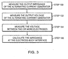
- Fig. 3 is a high-level flow chart illustrating exemplary steps involved in calculating electrode-body interface impedance according to an embodiment of the present invention.
- the present invention relates to a system and method for determining the impedance of an electrode, for example a skin electrode, at the electrode-body interface.
- the electrode may be used in ECG and EEG gating and monitoring, defibrillators, stress testing, transcutaneous nerve stimulators, depth of anesthesia monitoring systems, EMG monitors, CT scanners, MRIs, ultrasounds, lithotripters, and any other device for which skin electrodes are required for measurement or current delivery.
- the electrode-body impedance of one of the electrodes may be calculated using the voltage difference between that electrode and a plurality of other electrodes, and the voltage and impedance of an alternating current generator in communication with the electrodes.
- Fig. 1 is a highly schematic diagram illustrating an automated electrode-body interface impedance measurement system, according to an embodiment of the present invention.
- the impedance measurement system 8 includes a processor 10, an alternating current generator 12, a switch 22, and a plurality of electrodes.
- a plurality of electrodes are connected to the switch 22.
- the switch 22 is in electrical communication with both the alternating current generator 12 and the processor 10 and permits the user to select the appropriate electrodes 16-20 for the selected impedance measurement, for example, the first electrode 16.
- the processor 10 controls both the alternating current generator 12 and the switch 22.
- the processor 10 turns on the alternating current generator 12, to enable the impedance measurement, and turns off the alternating current generator 12 after the calculation has been completed.
- the alternating current generator 12 applies a voltage through the switch 22, which causes a current to flow to the first electrode 16, through the patient, to the second electrode 18 and the third electrode 20, which may be paralleled.
- the processor 10 measures the resultant voltage and uses that voltage along with the impedance of and voltage of the alternating current generator 12 to calculate the impedance of the electrodes 16-20. The measurement and calculation is then repeated for each of the two remaining electrodes 18 and 20.
- the electrodes may be any electrode used by one of skill in the art to measure electrical activity in a patient. Depending on what electrical activity is being measured, there can be three, four, five, six, or more electrodes. For ECG monitoring and gating, three or more electrodes may be used. For EEG monitoring and gating as few as two and as many as 64 electrodes may be used. For a stress test, up to twelve electrodes may be used. For a defibrillator, two or more electrodes may be used. In the illustrated embodiment, three electrodes are shown to measure the ECG of a patient. Although other types of measurements are possible and more electrodes may be used, in discussing the aspects of the present invention, an exemplary three electrodes will be used in connection with an ECG monitor.
- the alternating current generator 12 may be a 10 hertz generator that produces an alternating current which is applied to the electrodes 16-20.
- the alternating current generator 12 may produce a current in the range of 10-15 microamps RMS.
- the alternating current generator 12 may produce a variety of waveforms, including triangular or square voltage waveforms.
- the alternating current generator 12 has an output voltage associated with it, in the range of 0.5 volts RMS to 5.0 volts RMS and an output impedance in the range 350 kohms to 450 kohms.
- the voltage between the electrodes 16-20 is one parameter that is used to determine a selected electrode's impedance. Since it is difficult to have a zero ohm reference point on a patient's body, the measurement of the impedance of one electrode, for example, the first electrode 16, in one embodiment is made by paralleling, i.e. electrically shorting together, the other two electrodes, i.e. the second electrode 18 and the third electrode 20. Then, the voltage difference between the first electrode 16 and the parallel combination of the second electrode 18 and the third electrode 20 is used for the calculation of the impedance at the electrode-body interface of the first electrode 16.
- the current generator 12 produces a constant current output.
- the impedance of an electrode is linearly related to the voltage between the electrodes, i.e. the impedance of the first electrode 16 is linearly related to the voltage difference between the first electrode 16 and the voltage of the parallel combination of the second electrode 18 and the third electrode 20, as governed by the following equation:
- Z 2 is the unknown impedance
- k is an empirical constant of proportionality
- E 2 is the voltage difference between the first electrode 16 and the parallel combination of the second electrode 18 and the third electrode 20.
- the alternating current generator 12 produces a variable current.
- the relationship between the voltage difference between the first electrode 16 and the voltage of the parallel combination of the second electrode 18 and the third electrode 20, and the impedance of the first electrode 16 is no longer linear. Rather it is governed by the following equation:
- Z 2 is the unknown impedance of the first electrode 16
- Z 1 is the impedance of the alternating current generator 12
- E 1 is the output voltage of the alternating current generator 12
- E 2 is the voltage difference between the first electrode 16 and the parallel combination of the second electrode 18 and the third electrode 20.
- the output voltage and the impedance of the alternating current generator 12 are set values that are set by either the medical staff or set upon manufacture of the impedance measurement system 8.
- the processor 10 in various embodiments, is a microprocessor, a desktop or laptop computer, an embedded chip, or any type of processor that can be pre-programmed to perform calculations based on the measured voltages and impedance.
- the processor 10 controls the alternating current generator 12 and performs the impedance calculations.
- the type of calculation that the processor 10 performs is based on the whether the current output of the alternating current generator 12 is variable or constant. If the output current is constant, the processor 10 will perform the calculation in Eqn. 1 to determine the unknown impedance. If the output current is variable, the processor 10 will perform the calculation in Eqn. 2 to determine the unknown impedance.
- the processor may also control a signal to trigger or gate another device, such as an ECG monitor or a gamma camera.
- Fig. 2 is a more detailed schematic diagram of the system of Fig. 1 , illustrating an automated electrode-body interface impedance measurement system according to an embodiment of the present invention.
- the impedance measurement system 8 includes a processor 10; an alternating current generator 12; a plurality of electrodes (a first electrode 16, a second electrode 18, and a third electrode 20); two sets of switches (a first switch set 22 and a second switch set 24); a switch logic device 26; a synchronous rectifier 28; a plurality of isolators (a first isolator 30 and a second isolator 32); an analog to digital converter 34; a display 36; and optionally a clinical device 38.
- a plurality of electrodes are connected to a first switch set 22 and a second switch set 24.
- Each switch set 22 and 24 contain one or more internal switches.
- An exemplary switch set 22, 24 contains three internal switches, one for each electrode: a first internal switch 22A, a second internal switch 22B, a third internal switch 22C, a fourth internal switch 24A, a fifth internal switch 24B, and a sixth internal switch 24C.
- Each of the switch sets 22 and 24 are connected to the alternating current generator 12.
- the alternating current generator 12 applies a voltage and a current flow to the three electrodes 16-20.
- the switch sets 22 and 24 and the alternating current generator 12 are controlled by the switch logic device 26, which is in turn controlled by the processor 10.
- the processor 10 turns on the switch logic device 26, the synchronous rectifier 28, the analog to digital converter 34, and the alternating current generator 12 (to apply a voltage to the electrodes 16-20), and sets the switch sets 22 and 24 and the internal switches 22A-C and 24A-C.
- the impedance of each of the electrodes is measured. For example, a signal, corresponding to the voltage difference between the first electrode 16 and the paralleled second electrode 18 and third electrode 20, is rectified by the synchronous rectifier 28 and converted to a digital signal by the analog to digital converter 34, after passing through the isolator 30. The voltage difference is then read by the processor 10. The processor 10, using the above equations, will use this voltage value alone where the generator 12 is a constant current generator or in combination with the voltage and impedance of the alternating current generator 12, if the generator 12 is variable, to calculate the impedance of the first electrode 16. Once the processor 10 has performed the calculation, the display 36 will register a value for the electrode-body impedance of the first electrode 16.
- the process is then repeated first for the second electrode 18 and then for the third electrode 20.
- the process of calculating all three electrode-body impedance values may take approximately 0.4 to 1.0 seconds, but preferably 0.6 seconds.
- a clinical device 36 may also be controlled by the processor 10 and connected to the impedance measurement system 8. Once the calculation of the electrode-body impedance of all three electrodes is completed, the processor shuts off the synchronous rectifier 26, the alternating current generator 12, and the analog to digital to converter 34.
- the plurality of switches are not limited to two switch sets 22, 24, but can include any number of switch sets 22, 24 necessary for the number of electrodes being used.
- the switch sets 22, 24 may be used to isolate the appropriate electrode. For example, if the impedance of the first electrode 16 is to be measured, the switch sets 22, 24 will be set to create a circuit between the first electrode 16 and the paralleled second electrode 18 and the third electrode 20. More specifically, the first internal switch 24A (corresponding to the first electrode 16) will be closed and the second and third internal switches 22B and 22C (corresponding to the second electrode 18 and the third electrode 20, respectively) will remain open in the first switch set 22.
- the fifth and sixth internal switches 24B and 24C (corresponding to the second electrode 18 and the third electrode 20) will be closed, while the fourth internal switch 24A (corresponding to the first electrode 16) will remain open.
- the first switch set 22 and the second switch set 24 comprise field effect transistor (“FET”) switches.
- the switch logic device 26 controls the switches 22 and 24, through the processor 10.
- the processor 10 produces a digital output to the switch logic device 26.
- the switch logic device 26 turns on the alternating current generator 12.
- the switch logic device 26 then directs the first switch set 22 to close the first internal switch 22A and open the second and third internal switches 22B, 22C.
- a third digital output causes the second switch 24 to open fourth internal switch 24A and close the fifth and sixth internal switches 24B, 24C.
- the switch logic device 26 turns off the alternating current generator 12.
- the sequence may be repeated to determine the impedance of the second electrode 18 and the third electrode 20.
- the alternating current generator 12 is shut off as the alternating current generator 12 may cause interference with the ECG signal when the impedance measurement system 8 is used with, for example, an ECG monitoring or gating device.
- the synchronous rectifier 28 rectifies the signal from the alternating current generator 12.
- a full wave rectifier may be used, but the use of a synchronous rectifier expedites the sampling of the peak amplitude of the waveform generated by the alternating current generator 12.
- the plurality of isolators are used to isolate the patient or body 10 from the high voltage electronics.
- the first isolator 30 and the second isolator 32 may be optical isolators, transformers, or analog isolators.
- the analog to digital converter 34 converts the analog signal from the synchronous rectifier 28 into a digital signal to be read by the processor 10. As illustrated, the analog to digital converter 34 is on the non-isolated side of the impedance measurement system 8. However, in other embodiments, the analog to digital converter may be located on the isolated side of the impedance measurement system 8.
- the display 36 may be any device known to one of skill in the art to display the output of a processor, such as a computer monitor or a LCD screen.
- the display 36 may show the electrode-body impedance for all of the electrodes used in the monitoring or triggering process to be performed. Three electrodes are illustrated in Figure 2 , thus, the display 36 will show the impedance of the first electrode 16, the second electrode 18, and the third electrode 18.
- the display 36 may include a series of blinking lights to indicate the impedance level at the electrode-body interface. For example a pair of red and green lights may be used: red signaling that the impedance is too high, green signaling an acceptable impedance. Additionally, three lights, red, green and yellow may be used, where yellow serves as a warning that the impedance may not be at an optimal level.
- a user such as the medical staff, or the service provider for the system, may pre-configure the impedance levels for each of the blinking lights. Alternatively, an alarm may sound when the impedance level of the electrode-body interface for an electrode is too high. The alarm signals to the medical staff to continue to prepare the patient.
- the clinical device 38 may be, but is not limited to, the following: a gamma camera, a stress test ECG, an EEG machine, an EEG monitor, a transcutaneous nerve stimulator, a depth of anesthesia monitoring system, an EMG monitor, a CT scanner, a MR1, an ultrasound, a lithotripter, a defibrillator, or any other device for which skin electrodes are required for measurement or current delivery.
- the impedance measurement system 8 functions as described above. Once the impedance is measured, the medical staff may proceed to implement the clinical device 38.
- the impedance measurement system 8 simply alerts the user of the other device of the impedance level at the electrode-body interface. Once the medical staff is alerted, the medical staff may proceed with the operation of the clinical device 38 or the medical staff may continue the preparation of the patient. In one embodiment, the impedance measurement system 8 will shut off the clinical device, such that the clinical device 38 will not operate until the impedance at the electrode-body interface has reached a pre-set level.
- Fig. 3 is a high-level flow chart illustrating exemplary steps involved in calculating electrode-body interface impedance according to an embodiment of the present invention.
- the steps include (1) measuring an output impedance of the alternating current generator (Step 100); (2) measuring an output voltage of the alternating current generator (Step 102); (3) measuring a voltage between two or more electrodes (Step 104); and (4) calculating an impedance at the electrode-body interface (Step 106).
- the calculation of the impedance at the electrode-body interface is performed using either Eqn. 1 or Eqn. 2 above, depending of whether the alternating current produces a constant current or a variable current, respectively.
Landscapes
- Health & Medical Sciences (AREA)
- Life Sciences & Earth Sciences (AREA)
- Animal Behavior & Ethology (AREA)
- Public Health (AREA)
- Engineering & Computer Science (AREA)
- Biomedical Technology (AREA)
- Heart & Thoracic Surgery (AREA)
- Veterinary Medicine (AREA)
- Biophysics (AREA)
- General Health & Medical Sciences (AREA)
- Medical Informatics (AREA)
- Physics & Mathematics (AREA)
- Pathology (AREA)
- Molecular Biology (AREA)
- Surgery (AREA)
- Radiology & Medical Imaging (AREA)
- Nuclear Medicine, Radiotherapy & Molecular Imaging (AREA)
- Cardiology (AREA)
- Measurement And Recording Of Electrical Phenomena And Electrical Characteristics Of The Living Body (AREA)
Priority Applications (1)
| Application Number | Priority Date | Filing Date | Title |
|---|---|---|---|
| EP11195327.9A EP2460465B1 (en) | 2006-08-25 | 2007-08-20 | Automated ECG lead impedance measurement integrated into ECG gating circuitry |
Applications Claiming Priority (2)
| Application Number | Priority Date | Filing Date | Title |
|---|---|---|---|
| US11/509,928 US7818058B2 (en) | 2006-08-25 | 2006-08-25 | Automated ECG lead impedance measurement integrated into ECG gating circuitry |
| PCT/US2007/018391 WO2008027237A1 (en) | 2006-08-25 | 2007-08-20 | Automated ecg lead impedance measurement integrated into ecg gating circuitry |
Related Child Applications (1)
| Application Number | Title | Priority Date | Filing Date |
|---|---|---|---|
| EP11195327.9 Division-Into | 2011-12-22 |
Publications (2)
| Publication Number | Publication Date |
|---|---|
| EP2077749A1 EP2077749A1 (en) | 2009-07-15 |
| EP2077749B1 true EP2077749B1 (en) | 2012-08-08 |
Family
ID=38814403
Family Applications (2)
| Application Number | Title | Priority Date | Filing Date |
|---|---|---|---|
| EP07837071A Active EP2077749B1 (en) | 2006-08-25 | 2007-08-20 | Automated ecg lead impedance measurement integrated into ecg gating circuitry |
| EP11195327.9A Not-in-force EP2460465B1 (en) | 2006-08-25 | 2007-08-20 | Automated ECG lead impedance measurement integrated into ECG gating circuitry |
Family Applications After (1)
| Application Number | Title | Priority Date | Filing Date |
|---|---|---|---|
| EP11195327.9A Not-in-force EP2460465B1 (en) | 2006-08-25 | 2007-08-20 | Automated ECG lead impedance measurement integrated into ECG gating circuitry |
Country Status (4)
| Country | Link |
|---|---|
| US (1) | US7818058B2 (https=) |
| EP (2) | EP2077749B1 (https=) |
| JP (1) | JP5249220B2 (https=) |
| WO (1) | WO2008027237A1 (https=) |
Families Citing this family (33)
| Publication number | Priority date | Publication date | Assignee | Title |
|---|---|---|---|---|
| DE102007037103B4 (de) * | 2007-08-07 | 2015-12-17 | Siemens Aktiengesellschaft | Verfahren und Vorrichtung zum bildlichen Darstellen von funktionellen und elektrischen Aktivitäten des Gehirns |
| DE102008043103A1 (de) * | 2008-10-22 | 2010-04-29 | Alstrom Technology Ltd. | Vorrichtung und Verfahren zur Überwachung und/oder Analyse von Rotoren von elektrischen Maschinen im Betrieb |
| EP2564772A4 (en) * | 2010-04-28 | 2015-01-21 | Mi Tech Co Ltd | DEVICE FOR MEASURING THE INTERFACE IMPEDANCE BETWEEN A BODY AND A PACING ELECTRODE |
| US9980662B2 (en) | 2010-05-25 | 2018-05-29 | Neurowave Systems Inc. | Method and system for electrode impedance measurement |
| EP2717766B1 (en) * | 2011-06-10 | 2015-08-12 | Koninklijke Philips N.V. | Method and apparatus for selecting differential input leads |
| WO2014021883A1 (en) * | 2012-08-01 | 2014-02-06 | Draeger Medical Systems, Inc. | System and method for measuring contact impedance of an electrode |
| US8755873B2 (en) | 2012-09-21 | 2014-06-17 | Welch Allyn, Inc. | Evaluation of the quality of electrode contact with a skin surface |
| CN103622688B (zh) * | 2013-01-10 | 2018-02-13 | 中国科学院电子学研究所 | 一种可贴式心电、心阻抗集成监测传感器 |
| AU2014207265B2 (en) | 2013-01-21 | 2017-04-20 | Cala Health, Inc. | Devices and methods for controlling tremor |
| US12453853B2 (en) | 2013-01-21 | 2025-10-28 | Cala Health, Inc. | Multi-modal stimulation for treating tremor |
| CA2926112A1 (en) | 2013-10-23 | 2015-04-30 | Michael R. Girouard | Detecting seizures including loose electrode monitoring |
| DE102013021175B4 (de) * | 2013-12-17 | 2015-10-22 | Cerbomed Gmbh | Vorrichtung zur Aufbringung eines transkutanen elektrischen Stimulationsreizes |
| AU2015271774B2 (en) | 2014-06-02 | 2020-04-16 | Cala Health, Inc. | Systems and methods for peripheral nerve stimulation to treat tremor |
| EP4342516A3 (en) | 2015-06-10 | 2024-07-10 | Cala Health, Inc. | Systems and methods for peripheral nerve stimulation to treat tremor with detachable therapy and monitoring units |
| EP3328277A4 (en) | 2015-07-31 | 2019-03-06 | Cala Health, Inc. | SYSTEMS, DEVICES AND METHOD FOR TREATING OSTEOARTHRITIS |
| US10603482B2 (en) | 2015-09-23 | 2020-03-31 | Cala Health, Inc. | Systems and methods for peripheral nerve stimulation in the finger or hand to treat hand tremors |
| KR102638312B1 (ko) * | 2015-12-17 | 2024-02-19 | 삼성전자주식회사 | 3전극 센서를 이용한 생체 임피던스 측정 장치 및 방법 |
| AU2017211048B2 (en) | 2016-01-21 | 2022-03-10 | Cala Health, Inc. | Systems, methods and devices for peripheral neuromodulation for treating diseases related to overactive bladder |
| JP7133543B2 (ja) | 2016-08-25 | 2022-09-08 | カラ ヘルス,インコーポレイテッド | 末梢神経刺激による心機能不全の治療のためのシステムおよび方法 |
| EP3537961B1 (en) | 2016-11-10 | 2025-06-25 | The Research Foundation for The State University of New York | System, method and biomarkers for airway obstruction |
| TWI598073B (zh) | 2016-12-15 | 2017-09-11 | 財團法人工業技術研究院 | 生理訊號量測方法及生理訊號量測裝置 |
| US10368805B2 (en) | 2016-12-29 | 2019-08-06 | Drägerwerk AG & Co. KGaA | Electrode impedance measurement |
| EP3363354A1 (en) | 2017-02-21 | 2018-08-22 | Koninklijke Philips N.V. | An apparatus and method for measuring electrode impedance during electrophysiological measurements |
| US11331480B2 (en) | 2017-04-03 | 2022-05-17 | Cala Health, Inc. | Systems, methods and devices for peripheral neuromodulation for treating diseases related to overactive bladder |
| GB201708354D0 (en) * | 2017-05-25 | 2017-07-12 | Heartsine Tech Ltd | Testing of defibrillator electrodes |
| WO2019143790A1 (en) | 2018-01-17 | 2019-07-25 | Cala Health, Inc. | Systems and methods for treating inflammatory bowel disease through peripheral nerve stimulation |
| US10285646B1 (en) | 2018-02-27 | 2019-05-14 | CeriBell, Inc. | Connection quality assessment for EEG electrode arrays |
| US12543955B2 (en) * | 2018-11-26 | 2026-02-10 | The Johns Hopkins University | Apparatus and method for patient monitoring based on ultrasound modulation |
| US12251560B1 (en) * | 2019-08-13 | 2025-03-18 | Cala Health, Inc. | Connection quality determination for wearable neurostimulation systems |
| US11890468B1 (en) | 2019-10-03 | 2024-02-06 | Cala Health, Inc. | Neurostimulation systems with event pattern detection and classification |
| GB2598299B (en) * | 2020-08-20 | 2023-10-04 | Actegy Ltd | Apparatus for detecting electrical conductivity |
| US12233276B2 (en) | 2020-12-03 | 2025-02-25 | Physio-Control, Inc. | Automatic lead switching |
| DE112022005257T5 (de) * | 2021-11-03 | 2024-08-14 | Drägerwerk AG & Co. KGaA | System und verfahren zum anzeigen von impedanzinformationen für physiologische sensoren |
Family Cites Families (12)
| Publication number | Priority date | Publication date | Assignee | Title |
|---|---|---|---|---|
| US4245643A (en) * | 1979-08-15 | 1981-01-20 | Children's Hospital Medical Center | Method and apparatus for measuring the ohmic contact resistance of an electrode attached to body tissue |
| ZA858309B (en) * | 1984-11-06 | 1986-06-25 | Spacelabs Inc | Apparatus and method for automatic lead fail detection in electrocardiography |
| AU4907385A (en) | 1984-11-06 | 1986-05-15 | Spacelabs, Inc. | Lead fail detection in electrocardiography |
| JPH02243988A (ja) | 1989-03-17 | 1990-09-28 | Toshiba Corp | 核医学データ収集処理装置 |
| US5337230A (en) * | 1992-04-30 | 1994-08-09 | Hewlett-Packard Company | Signal processing circuits with digital programmability |
| US5904654A (en) * | 1995-10-20 | 1999-05-18 | Vital Insite, Inc. | Exciter-detector unit for measuring physiological parameters |
| US6076015A (en) * | 1998-02-27 | 2000-06-13 | Cardiac Pacemakers, Inc. | Rate adaptive cardiac rhythm management device using transthoracic impedance |
| US6347245B1 (en) * | 1999-07-14 | 2002-02-12 | Medtronic, Inc. | Medical device ECG marker for use in compressed data system |
| US6887239B2 (en) * | 2002-04-17 | 2005-05-03 | Sontra Medical Inc. | Preparation for transmission and reception of electrical signals |
| US7986994B2 (en) * | 2002-12-04 | 2011-07-26 | Medtronic, Inc. | Method and apparatus for detecting change in intrathoracic electrical impedance |
| EP1690490B1 (en) * | 2003-11-11 | 2012-04-18 | Olympus Corporation | Capsule type medical device system |
| AU2006235722A1 (en) * | 2005-04-14 | 2006-10-19 | Hidalgo Limited | Apparatus and system for monitoring |
-
2006
- 2006-08-25 US US11/509,928 patent/US7818058B2/en active Active
-
2007
- 2007-08-20 EP EP07837071A patent/EP2077749B1/en active Active
- 2007-08-20 WO PCT/US2007/018391 patent/WO2008027237A1/en not_active Ceased
- 2007-08-20 JP JP2009525589A patent/JP5249220B2/ja not_active Expired - Fee Related
- 2007-08-20 EP EP11195327.9A patent/EP2460465B1/en not_active Not-in-force
Also Published As
| Publication number | Publication date |
|---|---|
| US20080051845A1 (en) | 2008-02-28 |
| WO2008027237A1 (en) | 2008-03-06 |
| US7818058B2 (en) | 2010-10-19 |
| EP2077749A1 (en) | 2009-07-15 |
| EP2460465B1 (en) | 2014-01-08 |
| EP2460465A1 (en) | 2012-06-06 |
| JP2010501253A (ja) | 2010-01-21 |
| JP5249220B2 (ja) | 2013-07-31 |
Similar Documents
| Publication | Publication Date | Title |
|---|---|---|
| EP2077749B1 (en) | Automated ecg lead impedance measurement integrated into ecg gating circuitry | |
| US6505079B1 (en) | Electrical stimulation of tissue for therapeutic and diagnostic purposes | |
| CA2546236C (en) | Determining stimulation levels for transcranial magnetic stimulation | |
| JP3138428B2 (ja) | 自動電流知覚しきい域測定装置および方法 | |
| JP3209523B2 (ja) | 神経系の自律部位の状態の決定に使用する専用装置 | |
| EP2409641A1 (en) | System and methods for performing neurophysiologic assessments during spine surgery | |
| Wollmann et al. | Safe performance of magnetic resonance of the heart in patients with magnetic resonance conditional pacemaker systems: the safety issue of the ESTIMATE study | |
| JP2010501253A5 (https=) | ||
| AU2009303836A1 (en) | Neurophysiologic monitoring system and related methods | |
| EP3330724B1 (en) | Simultaneous impedance testing method and apparatus | |
| US10130275B2 (en) | Method and apparatus for autonomic nervous system sensitivity-point testing | |
| Shellock et al. | Cardiac pacemakers and implantable cardioverter defibrillators: in vitro magnetic resonance imaging evaluation at 1.5-tesla | |
| EP3007619A1 (en) | Method and apparatus for autonomic nervous system sensitivity-point testing | |
| Recoskie et al. | Sensory and motor stimulation thresholds of the ulnar nerve from electric and magnetic field stimuli: implications to gradient coil operation | |
| JP2001276005A (ja) | 筋の活動度又は疲労度の評価装置 | |
| KR20120096846A (ko) | 안면 신경 모니터링 장치 및 방법 | |
| KR20110099117A (ko) | 상처의 진단 및 치료, 및 상처의 예후를 위한 전자 마커들의 표시 방법들 | |
| KR102903181B1 (ko) | 의료용 활성 임플란트의 인체 내 감지를 위한 장치 및 방법 | |
| EP4374782A1 (en) | Frequencies generator apparatus for analysis and correction of cellular imbalances, in particular of the human body | |
| Nakanishi et al. | Effects of magnetic stimulation compared to electrical stimulation on muscle contraction in quadriceps femoris muscle of healthy subjects: A pilot study | |
| WO2026041908A2 (en) | Multi-functional diagnostic measuring system for vertebrates | |
| Gunawan et al. | Conformity Evaluation of Cranial Electro-stimulation Prototype with Low Current Intensity and Smartphone Application | |
| RU2192166C2 (ru) | Способ диагностики функционального состояния организма по состоянию биологически активных точек | |
| JPH0628647B2 (ja) | 脳波測定装置 | |
| Brown | Induced Currents, Biological Effects of dB/dt in the Clinical Scanning Environment |
Legal Events
| Date | Code | Title | Description |
|---|---|---|---|
| PUAI | Public reference made under article 153(3) epc to a published international application that has entered the european phase |
Free format text: ORIGINAL CODE: 0009012 |
|
| 17P | Request for examination filed |
Effective date: 20090323 |
|
| AK | Designated contracting states |
Kind code of ref document: A1 Designated state(s): AT BE BG CH CY CZ DE DK EE ES FI FR GB GR HU IE IS IT LI LT LU LV MC MT NL PL PT RO SE SI SK TR |
|
| AX | Request for extension of the european patent |
Extension state: AL BA HR MK RS |
|
| 17Q | First examination report despatched |
Effective date: 20091214 |
|
| GRAP | Despatch of communication of intention to grant a patent |
Free format text: ORIGINAL CODE: EPIDOSNIGR1 |
|
| RIC1 | Information provided on ipc code assigned before grant |
Ipc: G01T 1/164 20060101ALI20120119BHEP Ipc: A61B 5/0424 20060101ALI20120119BHEP Ipc: G01R 31/02 20060101ALI20120119BHEP Ipc: A61B 5/053 20060101ALI20120119BHEP Ipc: A61B 5/00 20060101AFI20120119BHEP |
|
| DAX | Request for extension of the european patent (deleted) | ||
| GRAS | Grant fee paid |
Free format text: ORIGINAL CODE: EPIDOSNIGR3 |
|
| GRAA | (expected) grant |
Free format text: ORIGINAL CODE: 0009210 |
|
| AK | Designated contracting states |
Kind code of ref document: B1 Designated state(s): AT BE BG CH CY CZ DE DK EE ES FI FR GB GR HU IE IS IT LI LT LU LV MC MT NL PL PT RO SE SI SK TR |
|
| REG | Reference to a national code |
Ref country code: GB Ref legal event code: FG4D |
|
| REG | Reference to a national code |
Ref country code: CH Ref legal event code: EP Ref country code: AT Ref legal event code: REF Ref document number: 569290 Country of ref document: AT Kind code of ref document: T Effective date: 20120815 |
|
| REG | Reference to a national code |
Ref country code: IE Ref legal event code: FG4D |
|
| REG | Reference to a national code |
Ref country code: DE Ref legal event code: R096 Ref document number: 602007024654 Country of ref document: DE Effective date: 20121004 |
|
| REG | Reference to a national code |
Ref country code: NL Ref legal event code: VDEP Effective date: 20120808 |
|
| REG | Reference to a national code |
Ref country code: AT Ref legal event code: MK05 Ref document number: 569290 Country of ref document: AT Kind code of ref document: T Effective date: 20120808 |
|
| REG | Reference to a national code |
Ref country code: LT Ref legal event code: MG4D Effective date: 20120808 |
|
| PG25 | Lapsed in a contracting state [announced via postgrant information from national office to epo] |
Ref country code: LT Free format text: LAPSE BECAUSE OF FAILURE TO SUBMIT A TRANSLATION OF THE DESCRIPTION OR TO PAY THE FEE WITHIN THE PRESCRIBED TIME-LIMIT Effective date: 20120808 Ref country code: CY Free format text: LAPSE BECAUSE OF FAILURE TO SUBMIT A TRANSLATION OF THE DESCRIPTION OR TO PAY THE FEE WITHIN THE PRESCRIBED TIME-LIMIT Effective date: 20120808 Ref country code: IS Free format text: LAPSE BECAUSE OF FAILURE TO SUBMIT A TRANSLATION OF THE DESCRIPTION OR TO PAY THE FEE WITHIN THE PRESCRIBED TIME-LIMIT Effective date: 20121208 Ref country code: AT Free format text: LAPSE BECAUSE OF FAILURE TO SUBMIT A TRANSLATION OF THE DESCRIPTION OR TO PAY THE FEE WITHIN THE PRESCRIBED TIME-LIMIT Effective date: 20120808 Ref country code: FI Free format text: LAPSE BECAUSE OF FAILURE TO SUBMIT A TRANSLATION OF THE DESCRIPTION OR TO PAY THE FEE WITHIN THE PRESCRIBED TIME-LIMIT Effective date: 20120808 |
|
| PG25 | Lapsed in a contracting state [announced via postgrant information from national office to epo] |
Ref country code: PT Free format text: LAPSE BECAUSE OF FAILURE TO SUBMIT A TRANSLATION OF THE DESCRIPTION OR TO PAY THE FEE WITHIN THE PRESCRIBED TIME-LIMIT Effective date: 20121210 Ref country code: LV Free format text: LAPSE BECAUSE OF FAILURE TO SUBMIT A TRANSLATION OF THE DESCRIPTION OR TO PAY THE FEE WITHIN THE PRESCRIBED TIME-LIMIT Effective date: 20120808 Ref country code: GR Free format text: LAPSE BECAUSE OF FAILURE TO SUBMIT A TRANSLATION OF THE DESCRIPTION OR TO PAY THE FEE WITHIN THE PRESCRIBED TIME-LIMIT Effective date: 20121109 Ref country code: PL Free format text: LAPSE BECAUSE OF FAILURE TO SUBMIT A TRANSLATION OF THE DESCRIPTION OR TO PAY THE FEE WITHIN THE PRESCRIBED TIME-LIMIT Effective date: 20120808 Ref country code: BE Free format text: LAPSE BECAUSE OF FAILURE TO SUBMIT A TRANSLATION OF THE DESCRIPTION OR TO PAY THE FEE WITHIN THE PRESCRIBED TIME-LIMIT Effective date: 20120808 Ref country code: SE Free format text: LAPSE BECAUSE OF FAILURE TO SUBMIT A TRANSLATION OF THE DESCRIPTION OR TO PAY THE FEE WITHIN THE PRESCRIBED TIME-LIMIT Effective date: 20120808 Ref country code: SI Free format text: LAPSE BECAUSE OF FAILURE TO SUBMIT A TRANSLATION OF THE DESCRIPTION OR TO PAY THE FEE WITHIN THE PRESCRIBED TIME-LIMIT Effective date: 20120808 |
|
| REG | Reference to a national code |
Ref country code: CH Ref legal event code: PL |
|
| PG25 | Lapsed in a contracting state [announced via postgrant information from national office to epo] |
Ref country code: MC Free format text: LAPSE BECAUSE OF NON-PAYMENT OF DUE FEES Effective date: 20120831 Ref country code: NL Free format text: LAPSE BECAUSE OF FAILURE TO SUBMIT A TRANSLATION OF THE DESCRIPTION OR TO PAY THE FEE WITHIN THE PRESCRIBED TIME-LIMIT Effective date: 20120808 |
|
| PG25 | Lapsed in a contracting state [announced via postgrant information from national office to epo] |
Ref country code: ES Free format text: LAPSE BECAUSE OF FAILURE TO SUBMIT A TRANSLATION OF THE DESCRIPTION OR TO PAY THE FEE WITHIN THE PRESCRIBED TIME-LIMIT Effective date: 20121119 Ref country code: EE Free format text: LAPSE BECAUSE OF FAILURE TO SUBMIT A TRANSLATION OF THE DESCRIPTION OR TO PAY THE FEE WITHIN THE PRESCRIBED TIME-LIMIT Effective date: 20120808 Ref country code: CZ Free format text: LAPSE BECAUSE OF FAILURE TO SUBMIT A TRANSLATION OF THE DESCRIPTION OR TO PAY THE FEE WITHIN THE PRESCRIBED TIME-LIMIT Effective date: 20120808 Ref country code: RO Free format text: LAPSE BECAUSE OF FAILURE TO SUBMIT A TRANSLATION OF THE DESCRIPTION OR TO PAY THE FEE WITHIN THE PRESCRIBED TIME-LIMIT Effective date: 20120808 Ref country code: CH Free format text: LAPSE BECAUSE OF NON-PAYMENT OF DUE FEES Effective date: 20120831 Ref country code: LI Free format text: LAPSE BECAUSE OF NON-PAYMENT OF DUE FEES Effective date: 20120831 Ref country code: DK Free format text: LAPSE BECAUSE OF FAILURE TO SUBMIT A TRANSLATION OF THE DESCRIPTION OR TO PAY THE FEE WITHIN THE PRESCRIBED TIME-LIMIT Effective date: 20120808 |
|
| REG | Reference to a national code |
Ref country code: IE Ref legal event code: MM4A |
|
| PG25 | Lapsed in a contracting state [announced via postgrant information from national office to epo] |
Ref country code: SK Free format text: LAPSE BECAUSE OF FAILURE TO SUBMIT A TRANSLATION OF THE DESCRIPTION OR TO PAY THE FEE WITHIN THE PRESCRIBED TIME-LIMIT Effective date: 20120808 Ref country code: IT Free format text: LAPSE BECAUSE OF FAILURE TO SUBMIT A TRANSLATION OF THE DESCRIPTION OR TO PAY THE FEE WITHIN THE PRESCRIBED TIME-LIMIT Effective date: 20120808 |
|
| PLBE | No opposition filed within time limit |
Free format text: ORIGINAL CODE: 0009261 |
|
| STAA | Information on the status of an ep patent application or granted ep patent |
Free format text: STATUS: NO OPPOSITION FILED WITHIN TIME LIMIT |
|
| 26N | No opposition filed |
Effective date: 20130510 |
|
| PG25 | Lapsed in a contracting state [announced via postgrant information from national office to epo] |
Ref country code: BG Free format text: LAPSE BECAUSE OF FAILURE TO SUBMIT A TRANSLATION OF THE DESCRIPTION OR TO PAY THE FEE WITHIN THE PRESCRIBED TIME-LIMIT Effective date: 20121108 Ref country code: IE Free format text: LAPSE BECAUSE OF NON-PAYMENT OF DUE FEES Effective date: 20120820 |
|
| REG | Reference to a national code |
Ref country code: DE Ref legal event code: R097 Ref document number: 602007024654 Country of ref document: DE Effective date: 20130510 |
|
| PG25 | Lapsed in a contracting state [announced via postgrant information from national office to epo] |
Ref country code: MT Free format text: LAPSE BECAUSE OF FAILURE TO SUBMIT A TRANSLATION OF THE DESCRIPTION OR TO PAY THE FEE WITHIN THE PRESCRIBED TIME-LIMIT Effective date: 20120808 |
|
| PG25 | Lapsed in a contracting state [announced via postgrant information from national office to epo] |
Ref country code: TR Free format text: LAPSE BECAUSE OF FAILURE TO SUBMIT A TRANSLATION OF THE DESCRIPTION OR TO PAY THE FEE WITHIN THE PRESCRIBED TIME-LIMIT Effective date: 20120808 |
|
| PG25 | Lapsed in a contracting state [announced via postgrant information from national office to epo] |
Ref country code: LU Free format text: LAPSE BECAUSE OF NON-PAYMENT OF DUE FEES Effective date: 20120820 |
|
| PG25 | Lapsed in a contracting state [announced via postgrant information from national office to epo] |
Ref country code: HU Free format text: LAPSE BECAUSE OF FAILURE TO SUBMIT A TRANSLATION OF THE DESCRIPTION OR TO PAY THE FEE WITHIN THE PRESCRIBED TIME-LIMIT Effective date: 20070820 |
|
| REG | Reference to a national code |
Ref country code: FR Ref legal event code: PLFP Year of fee payment: 10 |
|
| REG | Reference to a national code |
Ref country code: FR Ref legal event code: PLFP Year of fee payment: 11 |
|
| REG | Reference to a national code |
Ref country code: FR Ref legal event code: PLFP Year of fee payment: 12 |
|
| P01 | Opt-out of the competence of the unified patent court (upc) registered |
Effective date: 20230530 |
|
| PGFP | Annual fee paid to national office [announced via postgrant information from national office to epo] |
Ref country code: GB Payment date: 20250626 Year of fee payment: 19 |
|
| PGFP | Annual fee paid to national office [announced via postgrant information from national office to epo] |
Ref country code: FR Payment date: 20250610 Year of fee payment: 19 |
|
| PGFP | Annual fee paid to national office [announced via postgrant information from national office to epo] |
Ref country code: DE Payment date: 20250624 Year of fee payment: 19 |