EP2077368A1 - Sensor for automatic door device and automatic door device using the sensor - Google Patents
Sensor for automatic door device and automatic door device using the sensor Download PDFInfo
- Publication number
- EP2077368A1 EP2077368A1 EP07828342A EP07828342A EP2077368A1 EP 2077368 A1 EP2077368 A1 EP 2077368A1 EP 07828342 A EP07828342 A EP 07828342A EP 07828342 A EP07828342 A EP 07828342A EP 2077368 A1 EP2077368 A1 EP 2077368A1
- Authority
- EP
- European Patent Office
- Prior art keywords
- light
- sensor
- human
- automatic door
- emitting
- Prior art date
- Legal status (The legal status is an assumption and is not a legal conclusion. Google has not performed a legal analysis and makes no representation as to the accuracy of the status listed.)
- Granted
Links
Images


Classifications
-
- E—FIXED CONSTRUCTIONS
- E05—LOCKS; KEYS; WINDOW OR DOOR FITTINGS; SAFES
- E05F—DEVICES FOR MOVING WINGS INTO OPEN OR CLOSED POSITION; CHECKS FOR WINGS; WING FITTINGS NOT OTHERWISE PROVIDED FOR, CONCERNED WITH THE FUNCTIONING OF THE WING
- E05F15/00—Power-operated mechanisms for wings
- E05F15/40—Safety devices, e.g. detection of obstructions or end positions
- E05F15/42—Detection using safety edges
- E05F15/43—Detection using safety edges responsive to disruption of energy beams, e.g. light or sound
-
- E—FIXED CONSTRUCTIONS
- E05—LOCKS; KEYS; WINDOW OR DOOR FITTINGS; SAFES
- E05F—DEVICES FOR MOVING WINGS INTO OPEN OR CLOSED POSITION; CHECKS FOR WINGS; WING FITTINGS NOT OTHERWISE PROVIDED FOR, CONCERNED WITH THE FUNCTIONING OF THE WING
- E05F15/00—Power-operated mechanisms for wings
- E05F15/70—Power-operated mechanisms for wings with automatic actuation
- E05F15/73—Power-operated mechanisms for wings with automatic actuation responsive to movement or presence of persons or objects
- E05F15/74—Power-operated mechanisms for wings with automatic actuation responsive to movement or presence of persons or objects using photoelectric cells
-
- E—FIXED CONSTRUCTIONS
- E05—LOCKS; KEYS; WINDOW OR DOOR FITTINGS; SAFES
- E05F—DEVICES FOR MOVING WINGS INTO OPEN OR CLOSED POSITION; CHECKS FOR WINGS; WING FITTINGS NOT OTHERWISE PROVIDED FOR, CONCERNED WITH THE FUNCTIONING OF THE WING
- E05F15/00—Power-operated mechanisms for wings
- E05F15/40—Safety devices, e.g. detection of obstructions or end positions
- E05F15/42—Detection using safety edges
- E05F15/43—Detection using safety edges responsive to disruption of energy beams, e.g. light or sound
- E05F2015/434—Detection using safety edges responsive to disruption of energy beams, e.g. light or sound with optical sensors
- E05F2015/435—Detection using safety edges responsive to disruption of energy beams, e.g. light or sound with optical sensors by interruption of the beam
- E05F2015/436—Detection using safety edges responsive to disruption of energy beams, e.g. light or sound with optical sensors by interruption of the beam the beam being parallel to the wing edge
-
- E—FIXED CONSTRUCTIONS
- E05—LOCKS; KEYS; WINDOW OR DOOR FITTINGS; SAFES
- E05F—DEVICES FOR MOVING WINGS INTO OPEN OR CLOSED POSITION; CHECKS FOR WINGS; WING FITTINGS NOT OTHERWISE PROVIDED FOR, CONCERNED WITH THE FUNCTIONING OF THE WING
- E05F15/00—Power-operated mechanisms for wings
- E05F15/40—Safety devices, e.g. detection of obstructions or end positions
- E05F15/42—Detection using safety edges
- E05F2015/487—Fault detection of safety edges
-
- E—FIXED CONSTRUCTIONS
- E05—LOCKS; KEYS; WINDOW OR DOOR FITTINGS; SAFES
- E05Y—INDEXING SCHEME RELATING TO HINGES OR OTHER SUSPENSION DEVICES FOR DOORS, WINDOWS OR WINGS AND DEVICES FOR MOVING WINGS INTO OPEN OR CLOSED POSITION, CHECKS FOR WINGS AND WING FITTINGS NOT OTHERWISE PROVIDED FOR, CONCERNED WITH THE FUNCTIONING OF THE WING
- E05Y2400/00—Electronic control; Power supply; Power or signal transmission; User interfaces
- E05Y2400/10—Electronic control
- E05Y2400/30—Electronic control of motors
- E05Y2400/36—Speed control, detection or monitoring
-
- E—FIXED CONSTRUCTIONS
- E05—LOCKS; KEYS; WINDOW OR DOOR FITTINGS; SAFES
- E05Y—INDEXING SCHEME RELATING TO HINGES OR OTHER SUSPENSION DEVICES FOR DOORS, WINDOWS OR WINGS AND DEVICES FOR MOVING WINGS INTO OPEN OR CLOSED POSITION, CHECKS FOR WINGS AND WING FITTINGS NOT OTHERWISE PROVIDED FOR, CONCERNED WITH THE FUNCTIONING OF THE WING
- E05Y2400/00—Electronic control; Power supply; Power or signal transmission; User interfaces
- E05Y2400/10—Electronic control
- E05Y2400/45—Control modes
- E05Y2400/452—Control modes for saving energy
-
- E—FIXED CONSTRUCTIONS
- E05—LOCKS; KEYS; WINDOW OR DOOR FITTINGS; SAFES
- E05Y—INDEXING SCHEME RELATING TO HINGES OR OTHER SUSPENSION DEVICES FOR DOORS, WINDOWS OR WINGS AND DEVICES FOR MOVING WINGS INTO OPEN OR CLOSED POSITION, CHECKS FOR WINGS AND WING FITTINGS NOT OTHERWISE PROVIDED FOR, CONCERNED WITH THE FUNCTIONING OF THE WING
- E05Y2400/00—Electronic control; Power supply; Power or signal transmission; User interfaces
- E05Y2400/10—Electronic control
- E05Y2400/45—Control modes
- E05Y2400/458—Control modes for generating service signals
-
- E—FIXED CONSTRUCTIONS
- E05—LOCKS; KEYS; WINDOW OR DOOR FITTINGS; SAFES
- E05Y—INDEXING SCHEME RELATING TO HINGES OR OTHER SUSPENSION DEVICES FOR DOORS, WINDOWS OR WINGS AND DEVICES FOR MOVING WINGS INTO OPEN OR CLOSED POSITION, CHECKS FOR WINGS AND WING FITTINGS NOT OTHERWISE PROVIDED FOR, CONCERNED WITH THE FUNCTIONING OF THE WING
- E05Y2400/00—Electronic control; Power supply; Power or signal transmission; User interfaces
- E05Y2400/10—Electronic control
- E05Y2400/52—Safety arrangements
- E05Y2400/53—Wing impact prevention or reduction
-
- E—FIXED CONSTRUCTIONS
- E05—LOCKS; KEYS; WINDOW OR DOOR FITTINGS; SAFES
- E05Y—INDEXING SCHEME RELATING TO HINGES OR OTHER SUSPENSION DEVICES FOR DOORS, WINDOWS OR WINGS AND DEVICES FOR MOVING WINGS INTO OPEN OR CLOSED POSITION, CHECKS FOR WINGS AND WING FITTINGS NOT OTHERWISE PROVIDED FOR, CONCERNED WITH THE FUNCTIONING OF THE WING
- E05Y2400/00—Electronic control; Power supply; Power or signal transmission; User interfaces
- E05Y2400/60—Power supply; Power or signal transmission
- E05Y2400/61—Power supply
-
- E—FIXED CONSTRUCTIONS
- E05—LOCKS; KEYS; WINDOW OR DOOR FITTINGS; SAFES
- E05Y—INDEXING SCHEME RELATING TO HINGES OR OTHER SUSPENSION DEVICES FOR DOORS, WINDOWS OR WINGS AND DEVICES FOR MOVING WINGS INTO OPEN OR CLOSED POSITION, CHECKS FOR WINGS AND WING FITTINGS NOT OTHERWISE PROVIDED FOR, CONCERNED WITH THE FUNCTIONING OF THE WING
- E05Y2600/00—Mounting or coupling arrangements for elements provided for in this subclass
- E05Y2600/40—Mounting location; Visibility of the elements
- E05Y2600/45—Mounting location; Visibility of the elements in or on the fixed frame
-
- E—FIXED CONSTRUCTIONS
- E05—LOCKS; KEYS; WINDOW OR DOOR FITTINGS; SAFES
- E05Y—INDEXING SCHEME RELATING TO HINGES OR OTHER SUSPENSION DEVICES FOR DOORS, WINDOWS OR WINGS AND DEVICES FOR MOVING WINGS INTO OPEN OR CLOSED POSITION, CHECKS FOR WINGS AND WING FITTINGS NOT OTHERWISE PROVIDED FOR, CONCERNED WITH THE FUNCTIONING OF THE WING
- E05Y2900/00—Application of doors, windows, wings or fittings thereof
- E05Y2900/10—Application of doors, windows, wings or fittings thereof for buildings or parts thereof
- E05Y2900/13—Application of doors, windows, wings or fittings thereof for buildings or parts thereof characterised by the type of wing
- E05Y2900/132—Doors
Landscapes
- Power-Operated Mechanisms For Wings (AREA)
Abstract
Description
- This invention relates to a sensor for an automatic door system and, more particularly, to such a sensor capable of detecting malfunction thereof. Also, this invention relates to an automatic door system with such sensor used therein.
- Some automatic door systems use optical sensors for controlling opening and closing operations of a door panel. An example of such automatic door systems is disclosed in
Patent Literature 1. According to the technology ofPatent Literature 1, detecting ranges for detecting the presence of a human or an object are set in outdoor and indoor sides of an door opening formed in a wall of a building. There are provided activating sensors for detecting the presence or absence of a human or an object in the detection ranges. An auxiliary sensor is disposed on jambs erected on both sides of the door opening. A light-emitter is disposed on one of the jambs, and a light-receiver is disposed on the other jamb. The light-emitter and the light-receiver are facing each other. The auxiliary sensor is employed for keeping the door panel open when the presence of a human or an object in the vicinity of the door opening is detected when the door is open. The detection is based on reception, by the light-receiver, of no light from the light-emitter because of the light from the light-emitter intercepted by the human or object. - Patent Literature 1:
JP 2002-227525 - The light-emitter or light-receiver of the above-described auxiliary sensor may malfunction. For example, if the light-emitter fails to emit light, no light is received by the light-receiver, which may result in erroneous judgment as if the light was intercepted by a human or an object, although no human or object has been detected. As a result, the door panel is kept open, which means that the closing ability of the automatic door system is degraded. When the light-receiver is not receiving light, it malfunctions to develop an output similar to an output developed when it receives light, the light-receiver makes an erroneous detection indicating that no human or object is being detected. As a result, the door panel is closed even when a human or an object is present near the door opening, which may cause the human or object to collide with the door panel. Such malfunctions may occur not only in an auxiliary sensor but also in an optical-type activating sensor.
- An object of the present invention is to provide a sensor for an automatic door, which can detect its own malfunction. Another object of the invention is to provide an automatic door system with improved closing ability and safety.
- A sensor for an automatic door system according to one aspect of the present invention includes light-emitting means and light-receiving means. The light-emitting means emits light onto a human or object passing area in the automatic door system. It is desirable to use infrared light emitting means, for example, as the light-emitting means. The light-receiving means develops a light-reception indicative signal in accordance with reception of light coming from the light-emitting means through the passing area. Any types of light-receiving means appropriate for receiving the light from the light-emitting means can be used. For example, when the light-receiving means develops no light-reception indicative signal when the light-emitting means emits light, it is judged that a human or an object has been detected, and, when the light-receiving means develops a light-reception indicative signal in response to the light from the light-emitting means, it is judged that a human or an object has not been detected. The light-emitting means and the light-receiving mean may be disposed to face each other across the passing area, for example. Alternatively, the light-emitting means and the light-receiving means may be disposed on the ceiling of the automatic door system so that the light emitted by the light-emitting means can be reflected by the floor surface, which forms a part of the passing area, and be incident on the light-receiving means when a human or an object is not in the passing area. In this alternative arrangement, too, the absence of the light-reception indicative signal may mean the detection of an object, whereas the presence of the light-reception indicative signal means the non-detection. The light-emitting means and the light-receiving means may be activating sensors for controlling the opening and closing of a door panel of the automatic door system. Alternatively, they may be used as an auxiliary sensor for judging whether a human or object is present in an area through which the door panel moves. Light-emission control means causes the light-emitting means to stop emitting light and, then, to resume emitting light. The judging means judges, in the absence of a human or object, that the sensor is operating normal, when the light-emitting means is in the state where it stops emitting light and, therefore, the light-receiving means is in such light-reception indicative signal state in which it does not receive the light and, then, the light-receiving means is placed in such light-reception indicative signal state where it receives the light from the light-emitting means with the light-emitting means placed in the state where it re-starts to emit light; otherwise the judging means judges that the sensor is malfunctioning.
- Although the light-emitting means is not emitting light, if the light-receiving means is malfunctioning, it may be in the same light-reception indicative signal state as the state in which it normally receives light from the light-emitting means. Accordingly, it is known that, when the light-emitting means is not emitting light, if the light-receiving means is in the same light-reception indicative signal state as the one in which it is not receiving light, the light-receiving means does not have the above-described failure. One of failures of the light-emitting means is failure to emit light. The fact that the light-emitting means is not malfunctioning can be known by causing the light-emitting means to emit light, with the light-receiving means being free of failure as described above, and by knowing that the light-receiving means is in the same light-reception indicative signal state as the state in which the light-receiving means is normally receiving light. In other cases, or more specifically, if the light-receiving means is not in the same light-reception indicative signal state as the state in which the light-receiving means is normally receiving light even after the light-emitting means has started to emit light, the light-receiving means is malfunctioning, and if the light-receiving means, which is operating normal, is not in the same light-reception indicative signal state as the state in which the light-receiving means is normally receiving light even after the light-emitting means has started to emit light, the light-emitting means is malfunctioning. In this way, it can be known that either one of the light-emitting and light-receiving means is malfunctioning.
- Controlling of the light-emitting means by the light-emission control means and judgment by the judging means may be done before the door panel of the automatic door system starts to close, or, in other words, when the door panel in the open state starts to close.
- With this arrangement, it can be known beforehand that a human or an-object would be sandwiched or urged by the door panel against an article when the door panel is closing because of malfunctioning of the automatic door system sensor. It is desirable that, when the sensor for the automatic door system is judged to be malfunctioning, the closing operation of the door panel be forbidden, or that the door panel be closed at a lower speed than in the normal operation.
- The described automatic door system sensor may be an auxiliary sensor for an automatic door system. As described previously, an auxiliary sensor is a sensor for use in judging whether a human or an object is present in a moving area through which the door panel moves when the open door panel is closed. The passing area is within the door panel moving area. Activating sensors having detection areas used for controlling the opening and closing of the door panel are disposed inside and outside the moving area. The controlling of the light-emitting means by the light-emission control means and the judging by the judging means may be done when the auxiliary sensor is not detecting a human or an object, although the detecting state of the activating sensors changes in a time sequential fashion within a predetermined time period. In other words, the controlling of the light-emitting means by the light-emission control means and the judging by the judging means may be done when the auxiliary sensor is not detecting a human or an object, although the activating sensor detects a human or an object on the indoor side of the automatic door system and, thereafter, the human or object is detected by the activating sensor on the outdoor side of the automatic door system, for example. The same can be applied to the case in which the auxiliary sensor is not detecting a human or an object, although the activating sensor detects a human or an object on the outdoor side of the automatic door system and, thereafter, the human or object is detected by the activating sensor on the indoor side of the automatic door system.
- The above-described judgment, involving the light-emitting means' stopping and re-starting emitting light, if done frequently, causes excessive current to flow frequently through the light-emitting means, which, in turn, shortens the life of the light-emitting means. To avoid it, only when the auxiliary sensor is not detect a human or an object while the activating sensor is detecting the human or the object, the above-described judgment, involving the light-emitting means' stopping and starting emitting light, is carried out, to thereby keep the life of the light-emitting means longer.
- In an arrangement in which the described automatic door system sensor according to the described aspect is used as an auxiliary sensor together with the activating sensors as in the above-described case, if the auxiliary sensor is judged to be malfunctioning, the door panel may be closed at a lower speed than the normal closing speed when the activating sensors judge that the human or the object has passed through the passing area. On the other hand, if the activating sensors judge that the human or the object has not passed through the passing area, the door panel is kept open.
- With this arrangement, even when the auxiliary sensor is malfunctioning, or out of order, the detection result provided by the activating sensors can be used to control the opening and closing of the door panel. At the same time, if it cannot be known whether a human or an object has passed or not, the door panel is kept open. Thus, without greatly degrading the safety of the system, the passage of humans and/or objects, together with the closing ability of the door system can be retained.
-
- [
FIGURE 1] FIGURE 1 is a side view showing a longitudinal cross-section of an automatic door system employing a sensor according to one embodiment of the present invention. - [
FIGURE 2] FIGURE 2 is a plan view of the automatic door system shown inFIGURE 1 . - [
FIGURE 3] FIGURE 3 is a block circuit diagram of the automatic door system shown inFIGURE 1 . - [
FIGURE 4] FIGURE 4 is a main flow chart of the processing executed by a door controller of the automatic door system shown inFIGURE 1 . - [
FIGURE 5] FIGURE 5 is a flow chart of a sensor check A in the main flow chart shown inFIGURE 4 . - [
FIGURE 6] FIGURE 6 is a flow chart of a sensor check B in the main flow chart shown inFIGURE 4 . - [
FIGURE 7] FIGURE 7 is a flow chart of the processing for coping with malfunction in the main flow chart shown inFIGURE 4 . - [
FIGURE 8] FIGURE 8 is a block circuit diagram of a modification of the automatic door system shown inFIGURE 1 . - In an automatic door system using a sensor according to one embodiment of the invention, a
door opening 6 is provided between awall 2 separating the inside and outside of a building and a securingwall 4, as shown inFIGURE 2 . Humans can go into and out of the building through thedoor opening 6. Adoor panel 8 is adapted to slide in the width direction of thedoor opening 6 to open and close thedoor opening 6. Although a single sliding door with a single door panel is shown, a double sliding door with two door panels sliding in mutually opposite directions can be used, or a swing door panel can be used instead. - As shown in
FIGURE 1 , an indoor-side activating sensor 12 is disposed on the indoor side of alintel 10 in the upper side of thedoor opening 6. The indoor-side activating sensor 12 is of an optical type, and provides an indoor-side detecting area 14 extending from the indoor-side activating sensor 12 toward the indoor-side floor surface near thedoor opening 6. The indoor-side activating sensor 12 includes a plurality of light-emitters and a plurality of light-receivers corresponding to the respective light-emitters. As shown inFIGURE 2 , light, e.g. an infrared light ray, is projected to eachsmall spot 14a, and the reflected light from eachsmall spot 14a can be received by an associated light-receiver. Thus, when no human or object is present in the indoor-side detecting area 14, reflected light is received by the light-receivers, and if a human or an object is present in the indoor-side detecting area 14, reflected light is not received by the light-receivers. Whether or not a human or an object is present in the indoor-side detecting area 14 is determined based on whether or not the light-receivers receive light. - Similarly, an outdoor-
side activating sensor 16 is disposed on the outdoor side of thelintel 10 as shown inFIGURE 1 , which provides, on the outdoor side, an outdoor-side detecting area 18 extending from the outdoor-side activating sensor 16 toward the outdoor-side floor surface near thedoor opening 6. The outdoor-side activating sensor 16, too, is arranged to project infrared light from its respective light-emitters onto a plurality ofsmall spots 18a on the outdoor-side floor surface, with associated light-receivers arranged to be able to receive reflected light from the respectivesmall spots 18a. Accordingly, as described above, whether or not a human or an object is present in the outdoor-side detecting area 18 is determined based on whether or not the light-receivers receive light. - Posts,
e.g. jambs door opening 6, facing each other across thedoor opening 6. Light-emitting means, e.g. light-emitter 26, of a photoelectric tubeauxiliary sensor 24, is disposed on thejamb 20, and light-receiving means of theauxiliary sensor 24, e.g. light-receiver 28, is disposed on thejamb 22. The light-emitter 26 projects light, e.g. infrared light, to the light-receiver 28 through an auxiliary detectingarea 30, all the time, as shown inFIGURE 2 . If no human or object is present in theauxiliary detecting area 30, the infrared light is received by the light-receiver 28, but, if a human or an object is present, the infrared light is intercepted by the human or object and, therefore, cannot be received by the light-receiver 28. In this way, whether or not a human or an object is present is determined depending on whether or not the light is received by light-receiver 28. It should be noted that, inFIGURE 2 , the sizes of the light-emitter 26 and the light-receiver 28 are exaggerated. - Control means, e.g. a
door controller 32, controls thedoor panel 8 based on the detection results of the indoor-side and outdoor-side activating sensors auxiliary sensor 24. Thedoor controller 32 is disposed within thelintel 10. - As shown in
FIGURE 3 , thedoor controller 32 is connected to the indoor-side activating sensor 12 and the outdoor-side activating sensor 16, through a bus, e.g. a CAN (Controller Area Network)bus 34. Theauxiliary sensor 24 is directly connected to thedoor controller 32. Thedoor controller 32 controls driving means, e.g. amotor 36, to cause thedoor panel 8 to slide to thereby open thedoor opening 6 upon detection of a human or an object by the indoor-side activating sensor 12 or the outdoor-side activating sensor 16, when thedoor opening 6 is closed with thedoor panel 8. When a predetermined time lapses from the opening of thedoor opening 6, with theauxiliary sensor 24 detecting no human, and with the activating sensor different from the one which previously detected the human or object detecting no human or an object, thedoor controller 32 causes thedoor panel 8 to slide in the opposite direction to thereby close thedoor opening 6. - The
door controller 32 is also connected to anelectric lock controller 38 via theCAN bus 34. Theelectric lock controller 38 is to control an electric lock for locking thedoor panel 8 in an immovable state when thedoor panel 8 is in the state where thedoor opening 6 is closed by thedoor panel 8. Receiving a locking instruction from thedoor controller 32, theelectric lock controller 38 energizes asolenoid 40, which drives the electric lock, to thereby cause the electric lock to lock thedoor panel 8. Adisplay device 42 is also connected to theCAN bus 34, on which the operating states of thedoor controller 32, the indoor-side activating sensor 12, the outdoor-side activating sensor 16 and theelectric lock controller 38 are displayed, and also through which operating parameters of these components are set. - When the light-
receiver 28 of theauxiliary sensor 24 is in the normal operating state, the light-receiver 28 does not receive light if the light-emitter 26 becomes out of order so that it does not project light. As a result, although no human or object is present in theauxiliary detecting area 30, theauxiliary sensor 24 makes an erroneous determination as if a human or object were present. In such case, although a human or object has passed through thedoor opening 6, thedoor opening 6 is kept open, so that the closing ability of the automatic door system is lost. Also, when the light-emitter 26 is operating in order, if the light-receiver 28 is out of order and, when a human or object is present in theauxiliary detecting area 30, develops a light-reception indicative signal same as the one developed when the light-receiver is receiving light, meaning that theauxiliary sensor 24 makes an erroneous determination as if no human or object were present, thedoor panel 8 is driven to close so that it may or may not collide with the human or object. To avoid it, in the automatic door system according to the embodiment, thedoor controller 32 examines whether or not theauxiliary sensor 24 is malfunctioning, in the following manner. - First, as shown in
FIGURE 4 , whether or not the indoor-side activating sensor 12 or the outdoor-side activating sensor 16 is detecting a human or an object is judged (Step S2). If the answer to this query is NO, Step S2 is repeated until the answer changes to YES. When the answer to the query made in Step S2 becomes YES, the opening operation to open thedoor panel 8 is carried out (Step S4). Subsequent to it, the sensor check A is carried out (Step S6). - As shown in
FIGURE 5 , in the sensor check A, it is determined whether or not theauxiliary sensor 24 detects a human or an object within a first set time after the detection in Step S2 of the human or object by the indoor-side activating sensor 12 or after the detection in Step S2 of the human or object by the outdoor-side activating sensor 16 (Step S8). (The first set time is, for example, the time required for a human or an object to pass through the indoor-side detecting area 14 and arrive at the auxiliary detectingarea 30, or the time required for a human or an object to pass through the outdoor-side detecting area 18 and arrive at the auxiliary detectingarea 30.) If the answer to this query is YES, theauxiliary sensor 24 can be thought to be in order, the processing of the sensor check A is finished. - If the answer to the query made in Step S8 is NO, while, in Step S2, it has been determined that the indoor-
side activating sensor 12 has detected a human or an object, it is determined whether or not the outdoor-side activating sensor 16 has detected the human or object within a second set time starting from the detection of the human or object by the indoor-side activating sensor 12, or, if Step S2 has determined that the outdoor-side activating sensor 16 has detected a human or an object, determination is made as to whether or not the indoor-side activating sensor 12 has detected the human or object within the second set time starting from the detection of the human or object by the outdoor-side activating sensor 16 (Step S10). The second set time is, for example, the time required for a human or an object to go from the indoor-side detecting area 14 through the auxiliary detectingarea 30 and arrive the outdoor-side detecting area 18, and also is the time required for a human or an object to go from the outdoor-side detecting area 18 through the auxiliary detectingarea 30 and arrive the indoor-side detecting area 14. - If the answer to the query in Step S10 is NO, it can be judged that the human or object remains in the indoor-
side detecting area 14 or in the outdoor-side detecting area 18, that the human or object has not yet passed through the auxiliary detectingarea 30, and that theauxiliary sensor 24 is not out of order. Therefore, the processing of the sensor check A is finished. - The answer YES to the query made in Step S10 may mean, for example, that, although a human or an object was detected in the indoor-
side detecting area 14 and, thereafter, the human or object is detected in the outdoor-side detecting area 18, theauxiliary sensor 24 has not detected the human or object, or that, although a human or an object was detected in the outdoor-side detecting area 18 and, thereafter, the human or object is detected in the indoor-side detecting area 14, theauxiliary sensor 24 has not detected the human or object. In other words, it means that, although the detection by the indoor-side activating sensor 12 and the outdoor-side activating sensor 16 changes time-sequentially, theauxiliary sensor 24 detects no human or object. Then, it is determined that theauxiliary sensor 24 is not in order (Step S12), and the sensor check A is finished. - Subsequent to the processing of the sensor check A, whether or not malfunctioning has been found in the sensor check A is determined (Step S14), as shown in
FIGURE 4 . If the answer to the query is YES and malfunctioning was found in the previous door opening and closing operation, too, a flag for instructing to re-check the auxiliary sensor is set (Step S16). In Step S16, if it was determined that malfunctioning was not found in the previous door operation, the current malfunctioning is stored for the processing of Step S16 in the next time. - In case that the answer to the query made in Step S14 is NO, or subsequent to Step S16, it is determined whether or not the indoor-
side activating sensor 12, the outdoor-side activating sensor 16, or theauxiliary sensor 24 is detecting a human or an object (Step S18). If the answer to the query is YES, Step S18 is repeated. When the answer to the query becomes NO, meaning that none of the indoor-side activating sensor 12, the outdoor-side activating sensor 16 and theauxiliary sensor 24 detects a human or object, it can be concluded that the human or object has gone from the indoor-side detecting area 14, passed through the auxiliary detectingarea 30 and gone out through the outdoor-side detecting area 18, or, conversely, the human or object has gone from the outdoor-side detecting area 18, passed through the auxiliary detectingarea 30 and gone out through the outdoor-side detecting area 14. - In such case, the operation to close the
door panel 8 is carried out, but, before it, whether the re-check flag has been set or not is determined (Step S20). If the answer is NO, it can be judged that theauxiliary sensor 24 need not be re-checked, and, therefore, the flag is reset and thedoor panel 8 is closed as usual (Step S22). Subsequent to Step S22, Step S2 is executed again. - If the answer to the query made in Step S20 is YES, or, in other words, if malfunctioning has been determined consecutively twice in the sensor check A, a sensor check B is executed (Step S24).
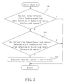
- In the sensor check B, light-emission from the light-
emitter 26 is stopped (Step S26). Next, it is judged if the stopping of light-emission can be perceived by the light-receiver 28 (Step S28). Step S28 is executed by determining if the light-receiver 28 is developing a signal which the light-receiver 28 would generate when it receives the light from the light-emitter 26. If the answer is NO, it can be concluded that the light-emitter 28 is in the light-receiving state same as the one in which it receives light although it receives no light, and, therefore, the light-receiver 28 is judged to be out of order. Then, it is judged that the auxiliary sensor is malfunctioning (Step S30). - If the answer to the query made in Step S28 is YES, it can be judged that the light-
receiver 28 is operating in order. Then, the light-emitter 26 is caused to start emitting light (Step S32). Whether or not a signal in response to the light-emission from the light-emitter 26 is developed by the light-receiver 28 is judged. In other words, whether the light-receiver 28 perceives the resumption of the emission of light is judged (Step S34). If the answer to the query made in Step S34 is YES, the light-emitter 26 can be judged to be operating in order, too. Then the sensor check B is finished. If the answer to the query made in Step S34 is NO, it can be judged that the light-emitter 26 is not emitting light and, therefore, is out of order. Then, Step S30 is executed, and a judgment that theauxiliary sensor 24 is out of order, is made. Then, the sensor check B is finished. - Subsequent to the sensor check B in Step S24, it is judged if the sensor check B has found malfunctioning, as shown in
FIGURE 4 (Step S36). If the answer to the query made in Step S36 is NO, or, in other words, if theauxiliary sensor 24 is judged to be operating in order, Step S22 is executed, the re-check flag is reset, and the usual door closing operation is done. After that, the processing is re-started from Step S2. On the other hand, if the answer to the query made in Step S36 is YES, or, in other words, if theauxiliary sensor 24 is judged to be malfunctioning, a malfunction flag is set and an error is indicated on the display device 42 (Step S38). Following it, malfunction coping processing is executed (Step S40). Based on the error indication, theauxiliary sensor 24 is repaired. The malfunction coping processing is executed in order to take care of the door system until the repair is made. - As shown in
FIGURE 7 , in the malfunction coping processing, first, it is determined whether the indoor-side activating sensor 12 or the outdoor-side activating sensor 16 is detecting a human or an object (Step S42). In other words, it is determined if a human or object is present in the indoor-side detecting area 14 or in the outdoor-side detecting area 18. If the answer to the query made in Step S42 is NO, Step S42 is repeated. If the answer is YES, the door opening operation takes place (Step S44). - Next, it is judged if either of the indoor-
side activating sensor 12 and the outdoor-side activating sensor 16 detects the human or object (Step S46). If the answer to this query is YES, the processing is repeated from Step S44. When the answer to the query made in Step S46 becomes NO, or, in other words, if the human or object is detected neither in the indoor-side detecting area 16 nor in the outdoor-side detecting area 18, it is determined if the indoor-side activating sensor 12 and the outdoor-side activating sensor 16 have detected the human or object in a time-sequential manner (Step S48). Specifically, it is determined if a human or an object is initially detected by the indoor-side activating sensor 12, and, a predetermined time after that, the outdoor-side activating sensor 16 detects the human or object or, conversely, if a human or an object is initially detected by the outdoor-side activating sensor 16, and, the predetermined time after that, the indoor-side activating sensor 12 detects the human or object. - If the answer to the query is YES, it can be concluded that the human or object has moved from the indoor-
side detecting area 14 through thedoor opening 6 to the outdoor-side detecting area 18, or, conversely, the human or object has moved from the outdoor-side detecting area 18 through thedoor opening 6 to the indoor-side detecting area 14. Then, thedoor panel 8 is closed at a lower speed. That is, thedoor panel 8 is closed at a speed lower than the usual closing speed (Step S50). Thedoor panel 8 is closed at a lower speed in order to secure safety of the human or object, since theauxiliary sensor 24 is malfunctioning and, therefore, cannot detect a human or object, if any, in the vicinity of thedoor opening 6. - The answer NO to the query made in Step S48 may mean that the human or object was in the indoor-
side detecting area 14, for example, but it did not proceed to thedoor opening 6, but proceeded away from thedoor opening 6 in the opposite direction, or that the human or object was in the outdoor-side detecting area 18, but it did not proceed to thedoor opening 6, but proceeded away from thedoor opening 6 in the opposite direction. Then, thedoor panel 8 is kept open (Step S52). Thedoor panel 8 is kept open for the purpose of securing the safety of the human or object, since it cannot be determined whether the human or object has passed. After the execution of Step S50 or S52, the processing is executed again from Step S42. Thus, once theauxiliary sensor 24 is judged to be out of order, theauxiliary sensor 24 does not take part in door opening and closing control, but the door opening and closing control is done using the activatingsensors - In the described embodiment, the
auxiliary sensor 24 is connected directly to thedoor controller 32, but theauxiliary sensor 24, too, can be connected to theCAN bus 34, as shown inFIGURE 8 , so that theauxiliary sensor 24 can transmit the detection result to thedoor controller 32 through theCAN bus 34. - In the described embodiment, the sensor check A is carried out to find the malfunction of the
auxiliary sensor 24 before making a closer examination through the sensor check B as to whether theauxiliary sensor 24 is out of order or not. This arrangement is employed for the following reason. In the sensor check B, the light-emitter 26 is caused to stop and resume emitting light, and, each time the emission is stopped and resumed, large current flows through the light-emitter 26. Therefore the life of the light-emitter 26 would be shortened if the sensor check B is performed each time thedoor panel 8 is closed. Therefore, the sensor check A, which does not involve making the light-emitter 26 to stop and resume emitting light, is performed first, and, only when it is considered that theauxiliary sensor 24 may be out of order, close checking is performed through the sensor check B, to thereby prevent the life of theauxiliary sensor 24 from being shortened. Thus, if the life of theauxiliary sensor 24 is not a significant matter, Steps S6, S14, S16 and S22 can be eliminated, and theauxiliary sensor 24 can be checked through the sensor check B. - The sensor check B is executed after Step S20, and, as a result, whether the
auxiliary sensor 24 is in order or not is checked before thedoor panel 8 is closed. Checking theauxiliary sensor 24 immediately before thedoor panel 8 is closed is for reducing the possibility of human's being sandwiched between the door panel and the jam or anything else. It should be noted, however, theauxiliary sensor 24 need not be checked before the closing operation, but it may be checked, for example, just after the power supply is connected to the automatic door system. Alternatively, the sensor check B may be performed when the opening and closing operation of thedoor panel 8 is not done for a predetermined time after the last opening and closing operation. - In the described embodiment, the sensor check B is performed when the malfunctioning is determined two consecutive times in the sensor check A. This is because, if a human or an object stays in the indoor-
side detecting area 14, for example, for a time longer than the second set time, theauxiliary sensor 24, even if it is operating in order, is judged to be out of order. However, theauxiliary sensor 24 may not be out of order even when it is judged to be out of order in one sensor check A. It may be arranged that the sensor check B is performed when the malfunctioning is determined a predetermined number of times more than two. - In the described embodiment, the malfunction coping processing is executed in Step S40 when the
auxiliary sensor 24 is judged to be out of order. This is for securing the closing ability, which is one of the advantages of the automatic door system, after a human or an object has passed through thedoor opening 6, while taking the safety into account, in spite of the malfunctioning of theauxiliary sensor 24. However, if it is desired to ensure the safety at the sacrifice of the closing property, thedoor opening 6 may be kept open after the execution of Step S38. - In the described embodiment, the activating
sensors auxiliary sensor 24 is not limited to one of photoelectric tube type, but it may be an infrared reflective type, like the activatingsensor 12, disposed beneath the lintel.
Claims (4)
- A sensor for an automatic door system, comprising:light-emitting means emitting light onto a passing area of said automatic door system, through which an object passes;light-receiving means receiving light from said light-emitting means that passed said passing area and developing a light-reception indicative signal;light-emission control means causing said light-emitting means to stop and, then, resume emitting light; andjudging means judging that said sensor is operating in order when said light-receiving means does not develop said light-reception indicative signal when said light-emitting means stops emitting light, and develops said light-reception indicative signal when said light-emitting means is caused to resume emitting light, otherwise said judging means judging said sensor to be out of order.
- The sensor for an automatic door system according to Claim 1, wherein the control of said light-emitting means by said light-emission control means and the judgment by said judging means are performed before closing a door panel of said automatic door system.
- The sensor for an automatic door system according to Claim 1, wherein said sensor is an auxiliary sensor for said automatic door system; said passing area is within an area through which said door panel moves; activating sensors are disposed inward and outward of said moving area, each of said activating sensors having a detecting area for controlling the opening and closing of said door panel; and the control of said light-emitting means by said light-emission control means and the judgment by said judging means are performed when said auxiliary sensor does not detect an object although the detection by said activating sensors changes in a time sequential fashion.
- An automatic door system including the sensor according to Claim 1, wherein said sensor is an auxiliary sensor for said automatic door system; said passing area is within an area through which said door panel moves; activating sensors are disposed inward and outward of said moving area, each of said activating sensors having a detecting area for controlling the opening and closing of said door panel; and, when said auxiliary sensor is judged to be out of order, said door panel is closed at a speed lower than a normal closing speed when said activating sensors determine that said object has passed said passing area, and is kept open when said activating sensors determine that said object has not passed said passing area.
Priority Applications (1)
| Application Number | Priority Date | Filing Date | Title |
|---|---|---|---|
| EP12193418.6A EP2562343B1 (en) | 2006-10-24 | 2007-09-25 | Automatic door system |
Applications Claiming Priority (2)
| Application Number | Priority Date | Filing Date | Title |
|---|---|---|---|
| JP2006288817A JP5242040B2 (en) | 2006-10-24 | 2006-10-24 | Sensor for automatic door device and automatic door device using this sensor |
| PCT/JP2007/068525 WO2008050565A1 (en) | 2006-10-24 | 2007-09-25 | Sensor for automatic door device and automatic door device using the sensor |
Related Child Applications (2)
| Application Number | Title | Priority Date | Filing Date |
|---|---|---|---|
| EP12193418.6A Division-Into EP2562343B1 (en) | 2006-10-24 | 2007-09-25 | Automatic door system |
| EP12193418.6A Division EP2562343B1 (en) | 2006-10-24 | 2007-09-25 | Automatic door system |
Publications (3)
| Publication Number | Publication Date |
|---|---|
| EP2077368A1 true EP2077368A1 (en) | 2009-07-08 |
| EP2077368A4 EP2077368A4 (en) | 2011-08-10 |
| EP2077368B1 EP2077368B1 (en) | 2017-08-09 |
Family
ID=39324372
Family Applications (2)
| Application Number | Title | Priority Date | Filing Date |
|---|---|---|---|
| EP12193418.6A Not-in-force EP2562343B1 (en) | 2006-10-24 | 2007-09-25 | Automatic door system |
| EP07828342.1A Not-in-force EP2077368B1 (en) | 2006-10-24 | 2007-09-25 | Method of controlling an automatic door system |
Family Applications Before (1)
| Application Number | Title | Priority Date | Filing Date |
|---|---|---|---|
| EP12193418.6A Not-in-force EP2562343B1 (en) | 2006-10-24 | 2007-09-25 | Automatic door system |
Country Status (7)
| Country | Link |
|---|---|
| US (1) | US8258455B2 (en) |
| EP (2) | EP2562343B1 (en) |
| JP (1) | JP5242040B2 (en) |
| CN (1) | CN101605959B (en) |
| CA (1) | CA2667252C (en) |
| HK (1) | HK1135746A1 (en) |
| WO (1) | WO2008050565A1 (en) |
Cited By (1)
| Publication number | Priority date | Publication date | Assignee | Title |
|---|---|---|---|---|
| US11098519B2 (en) | 2017-03-30 | 2021-08-24 | Assa Abloy Entrance Systems Ab | Door operator |
Families Citing this family (18)
| Publication number | Priority date | Publication date | Assignee | Title |
|---|---|---|---|---|
| JPS6093580A (en) * | 1983-10-27 | 1985-05-25 | Toshiba Corp | Sorting and counting system for money |
| JP2009155826A (en) * | 2007-12-25 | 2009-07-16 | Panasonic Electric Works Co Ltd | Automatic door device |
| CA2715184C (en) | 2008-03-19 | 2013-02-12 | Nabtesco Corporation | Sensor for use with automatic door |
| KR20120091036A (en) * | 2009-10-02 | 2012-08-17 | 베에스하 보쉬 운트 지멘스 하우스게랫테 게엠베하 | Door device for a household appliance, household appliance comprising such a door device and method for actuating a door device for a household appliance |
| JP5661799B2 (en) * | 2010-12-03 | 2015-01-28 | ナブテスコ株式会社 | Automatic door sensor |
| US20140258497A1 (en) * | 2011-10-06 | 2014-09-11 | Nabtesco Corporation | Management system for automatic door apparatus |
| CN103362393A (en) * | 2012-03-30 | 2013-10-23 | 鸿富锦精密工业(深圳)有限公司 | Automatic revolving door control system and method |
| US9970228B2 (en) | 2013-10-04 | 2018-05-15 | The Chamberlain Group, Inc. | Movable barrier safety sensor override |
| JP6351232B2 (en) * | 2013-10-25 | 2018-07-04 | 文化シヤッター株式会社 | Opening and closing body device |
| CN107431457A (en) * | 2015-03-23 | 2017-12-01 | 日本瑞翁株式会社 | Photoelectric conversion device |
| JP6655308B2 (en) * | 2015-06-29 | 2020-02-26 | ナブテスコ株式会社 | Control device |
| JP6306551B2 (en) * | 2015-10-01 | 2018-04-04 | ファナック株式会社 | Processing machine with door that can change opening and closing speed |
| US9850695B2 (en) | 2016-03-14 | 2017-12-26 | Ford Global Technologies Llc | Door restraint mechanism |
| CN106157408A (en) * | 2016-07-05 | 2016-11-23 | 重庆蓝岸通讯技术有限公司 | Smart lock with video monitoring remote unlocking system |
| JP7063601B2 (en) * | 2017-12-19 | 2022-05-09 | 東日本旅客鉄道株式会社 | Door pinch detection device and door pinch detection system |
| EP3794196B1 (en) * | 2018-05-18 | 2023-11-01 | ASSA ABLOY Entrance Systems AB | Control arrangement and entrance system comprising a control arrangement |
| CN111894383A (en) * | 2020-07-13 | 2020-11-06 | 沃行科技(南京)有限公司 | Intelligent bus anti-pinch method based on machine vision recognition |
| CN112049541A (en) * | 2020-08-19 | 2020-12-08 | 浙江工业大学 | Infrared radiation automatic door induction system |
Citations (2)
| Publication number | Priority date | Publication date | Assignee | Title |
|---|---|---|---|---|
| DE10100137A1 (en) * | 2000-01-04 | 2001-08-09 | Lear Corp | Non-contact optoelectronic system has control module which generates motor control signal to stop and reverse vehicle door upon detection of obstruction between transmitter and sensor |
| DE102007028979A1 (en) * | 2006-08-29 | 2008-03-06 | Schmidt, Hans, Dipl.-Ing. | Door for use in e.g. multi-storey car park, has light barrier comprising transmitter and receiver for infra-red light impulses, and receiver provided with control device, where function of receiver is displayed optically and/or acoustically |
Family Cites Families (14)
| Publication number | Priority date | Publication date | Assignee | Title |
|---|---|---|---|---|
| JPH0397397A (en) * | 1989-09-11 | 1991-04-23 | Yamatake Honeywell Co Ltd | Fault diagnosis device for sequence control system |
| JP3052491B2 (en) * | 1991-10-21 | 2000-06-12 | 日産自動車株式会社 | Automatic door safety devices for automobiles |
| CN2118139U (en) * | 1991-12-19 | 1992-10-07 | 沈阳黎明铝门窗工程公司 | Automatic microwave sensor for door |
| JP3234530B2 (en) * | 1996-04-26 | 2001-12-04 | 株式会社ナブコ | Self-diagnosis device for door sensor |
| US6020703A (en) * | 1997-06-30 | 2000-02-01 | Telmet; Juhan | Garage door opener |
| JP2000160936A (en) * | 1998-09-24 | 2000-06-13 | Harness Syst Tech Res Ltd | Catching preventing device |
| US7042492B2 (en) * | 1999-12-10 | 2006-05-09 | The Stanley Works | Automatic door assembly with video imaging device |
| JP4883738B2 (en) * | 2001-01-26 | 2012-02-22 | オプテックス株式会社 | Automatic door sensor |
| JP3846712B2 (en) * | 2002-09-06 | 2006-11-15 | オムロン株式会社 | Door opening / closing control device and method |
| US7061001B2 (en) * | 2003-06-27 | 2006-06-13 | Pitney Bowes Inc. | Method and apparatus for troubleshooting photosensors |
| JP4188251B2 (en) * | 2004-01-14 | 2008-11-26 | ナブテスコ株式会社 | Automatic door sensor |
| JP4485300B2 (en) * | 2004-09-14 | 2010-06-16 | ナブテスコ株式会社 | Automatic door |
| JP4731872B2 (en) * | 2004-10-12 | 2011-07-27 | 千蔵工業株式会社 | Automatic door opening and closing device |
| JP2006171839A (en) * | 2004-12-13 | 2006-06-29 | Nabtesco Corp | Entering/leaving person counting device and automatic door |
-
2006
- 2006-10-24 JP JP2006288817A patent/JP5242040B2/en active Active
-
2007
- 2007-09-25 US US12/446,726 patent/US8258455B2/en active Active
- 2007-09-25 WO PCT/JP2007/068525 patent/WO2008050565A1/en active Application Filing
- 2007-09-25 CA CA2667252A patent/CA2667252C/en active Active
- 2007-09-25 CN CN200780044743.7A patent/CN101605959B/en not_active Expired - Fee Related
- 2007-09-25 EP EP12193418.6A patent/EP2562343B1/en not_active Not-in-force
- 2007-09-25 EP EP07828342.1A patent/EP2077368B1/en not_active Not-in-force
-
2010
- 2010-02-26 HK HK10102035.1A patent/HK1135746A1/en not_active IP Right Cessation
Patent Citations (2)
| Publication number | Priority date | Publication date | Assignee | Title |
|---|---|---|---|---|
| DE10100137A1 (en) * | 2000-01-04 | 2001-08-09 | Lear Corp | Non-contact optoelectronic system has control module which generates motor control signal to stop and reverse vehicle door upon detection of obstruction between transmitter and sensor |
| DE102007028979A1 (en) * | 2006-08-29 | 2008-03-06 | Schmidt, Hans, Dipl.-Ing. | Door for use in e.g. multi-storey car park, has light barrier comprising transmitter and receiver for infra-red light impulses, and receiver provided with control device, where function of receiver is displayed optically and/or acoustically |
Non-Patent Citations (1)
| Title |
|---|
| See also references of WO2008050565A1 * |
Cited By (2)
| Publication number | Priority date | Publication date | Assignee | Title |
|---|---|---|---|---|
| US11098519B2 (en) | 2017-03-30 | 2021-08-24 | Assa Abloy Entrance Systems Ab | Door operator |
| AU2018241788B2 (en) * | 2017-03-30 | 2023-02-23 | Assa Abloy Entrance Systems Ab | Door operator |
Also Published As
| Publication number | Publication date |
|---|---|
| JP2008106476A (en) | 2008-05-08 |
| JP5242040B2 (en) | 2013-07-24 |
| EP2562343A1 (en) | 2013-02-27 |
| CA2667252A1 (en) | 2008-05-02 |
| EP2077368B1 (en) | 2017-08-09 |
| WO2008050565A1 (en) | 2008-05-02 |
| HK1135746A1 (en) | 2010-06-11 |
| CA2667252C (en) | 2014-05-06 |
| US20100024302A1 (en) | 2010-02-04 |
| CN101605959B (en) | 2014-01-01 |
| EP2562343B1 (en) | 2016-08-31 |
| CN101605959A (en) | 2009-12-16 |
| US8258455B2 (en) | 2012-09-04 |
| EP2077368A4 (en) | 2011-08-10 |
Similar Documents
| Publication | Publication Date | Title |
|---|---|---|
| EP2077368B1 (en) | Method of controlling an automatic door system | |
| EP0803632B1 (en) | Door sensor with self-diagnosing function | |
| JP5480379B2 (en) | Method for determining the functionality of an automatically closing door system, automatic door system and elevator system | |
| KR102490150B1 (en) | Method and device for monitoring lift car doors | |
| JP2002322872A (en) | Automatic door sensor | |
| JP2009155826A (en) | Automatic door device | |
| JP5297895B2 (en) | Elevator door equipment | |
| CN109502444B (en) | Detection system and detection method for door closing abnormity of elevator and elevator | |
| JP2002227525A (en) | Automatic door sensor | |
| JP4164244B2 (en) | Automatic door opening and closing control method | |
| JP5522916B2 (en) | Elevator door safety device | |
| KR20100046868A (en) | Safty control apparatus for automatic door | |
| JP2005201710A (en) | Sensor for automatic door | |
| JP2007276919A (en) | Obstacle detecting device for automatic door | |
| JP2005132598A (en) | Control device for elevator door | |
| JPH088239Y2 (en) | Obstacle detection device for architectural shutter | |
| JP2017019643A (en) | Passenger conveyor lid detection device | |
| WO2023058610A1 (en) | Automatic door, diagnostic device for automatic door, diagnostic method for automatic door, and diagnostic program for automatic door | |
| JPWO2003097507A1 (en) | Man conveyor automatic operation device | |
| JP2000053349A (en) | Door closing control device of elevator | |
| JP4460375B2 (en) | Switchgear | |
| JP2023066977A (en) | Platform door device, state determination device, area sensor state determination method, and area sensor state determination program | |
| JP2022078811A (en) | Automatic door, electronic device, method of operating automatic door, and program for operating automatic door | |
| JPH0342489A (en) | Abnormal fitting detecting method for elevator coupling device | |
| JP2022081321A (en) | Automatic door, diagnosis support device of optical sensor, optical sensor, diagnosis method for automatic door, diagnosis support method for optical sensor, diagnosis program for automatic door, and diagnosis support program for optical sensor |
Legal Events
| Date | Code | Title | Description |
|---|---|---|---|
| PUAI | Public reference made under article 153(3) epc to a published international application that has entered the european phase |
Free format text: ORIGINAL CODE: 0009012 |
|
| 17P | Request for examination filed |
Effective date: 20090428 |
|
| AK | Designated contracting states |
Kind code of ref document: A1 Designated state(s): AT BE BG CH CY CZ DE DK EE ES FI FR GB GR HU IE IS IT LI LT LU LV MC MT NL PL PT RO SE SI SK TR |
|
| A4 | Supplementary search report drawn up and despatched |
Effective date: 20110707 |
|
| RIC1 | Information provided on ipc code assigned before grant |
Ipc: E05F 15/00 20060101ALI20110701BHEP Ipc: E05F 15/20 20060101AFI20110701BHEP |
|
| 17Q | First examination report despatched |
Effective date: 20120704 |
|
| DAX | Request for extension of the european patent (deleted) | ||
| REG | Reference to a national code |
Ref country code: DE Ref legal event code: R079 Ref document number: 602007051959 Country of ref document: DE Free format text: PREVIOUS MAIN CLASS: E05F0015200000 Ipc: E05F0015430000 |
|
| RIC1 | Information provided on ipc code assigned before grant |
Ipc: E05F 15/43 20150101AFI20170213BHEP |
|
| GRAP | Despatch of communication of intention to grant a patent |
Free format text: ORIGINAL CODE: EPIDOSNIGR1 |
|
| STAA | Information on the status of an ep patent application or granted ep patent |
Free format text: STATUS: GRANT OF PATENT IS INTENDED |
|
| INTG | Intention to grant announced |
Effective date: 20170331 |
|
| GRAS | Grant fee paid |
Free format text: ORIGINAL CODE: EPIDOSNIGR3 |
|
| GRAA | (expected) grant |
Free format text: ORIGINAL CODE: 0009210 |
|
| STAA | Information on the status of an ep patent application or granted ep patent |
Free format text: STATUS: THE PATENT HAS BEEN GRANTED |
|
| AK | Designated contracting states |
Kind code of ref document: B1 Designated state(s): AT BE BG CH CY CZ DE DK EE ES FI FR GB GR HU IE IS IT LI LT LU LV MC MT NL PL PT RO SE SI SK TR |
|
| RAP1 | Party data changed (applicant data changed or rights of an application transferred) |
Owner name: NABTESCO CORPORATION |
|
| REG | Reference to a national code |
Ref country code: GB Ref legal event code: FG4D |
|
| REG | Reference to a national code |
Ref country code: CH Ref legal event code: EP Ref country code: AT Ref legal event code: REF Ref document number: 917049 Country of ref document: AT Kind code of ref document: T Effective date: 20170815 |
|
| REG | Reference to a national code |
Ref country code: CH Ref legal event code: NV Representative=s name: ISLER AND PEDRAZZINI AG, CH |
|
| REG | Reference to a national code |
Ref country code: IE Ref legal event code: FG4D |
|
| REG | Reference to a national code |
Ref country code: DE Ref legal event code: R096 Ref document number: 602007051959 Country of ref document: DE |
|
| PGFP | Annual fee paid to national office [announced via postgrant information from national office to epo] |
Ref country code: CH Payment date: 20170921 Year of fee payment: 11 Ref country code: DE Payment date: 20170928 Year of fee payment: 11 |
|
| REG | Reference to a national code |
Ref country code: NL Ref legal event code: MP Effective date: 20170809 |
|
| REG | Reference to a national code |
Ref country code: LT Ref legal event code: MG4D |
|
| REG | Reference to a national code |
Ref country code: AT Ref legal event code: MK05 Ref document number: 917049 Country of ref document: AT Kind code of ref document: T Effective date: 20170809 |
|
| PG25 | Lapsed in a contracting state [announced via postgrant information from national office to epo] |
Ref country code: FI Free format text: LAPSE BECAUSE OF FAILURE TO SUBMIT A TRANSLATION OF THE DESCRIPTION OR TO PAY THE FEE WITHIN THE PRESCRIBED TIME-LIMIT Effective date: 20170809 Ref country code: SE Free format text: LAPSE BECAUSE OF FAILURE TO SUBMIT A TRANSLATION OF THE DESCRIPTION OR TO PAY THE FEE WITHIN THE PRESCRIBED TIME-LIMIT Effective date: 20170809 Ref country code: AT Free format text: LAPSE BECAUSE OF FAILURE TO SUBMIT A TRANSLATION OF THE DESCRIPTION OR TO PAY THE FEE WITHIN THE PRESCRIBED TIME-LIMIT Effective date: 20170809 Ref country code: LT Free format text: LAPSE BECAUSE OF FAILURE TO SUBMIT A TRANSLATION OF THE DESCRIPTION OR TO PAY THE FEE WITHIN THE PRESCRIBED TIME-LIMIT Effective date: 20170809 Ref country code: NL Free format text: LAPSE BECAUSE OF FAILURE TO SUBMIT A TRANSLATION OF THE DESCRIPTION OR TO PAY THE FEE WITHIN THE PRESCRIBED TIME-LIMIT Effective date: 20170809 |
|
| PG25 | Lapsed in a contracting state [announced via postgrant information from national office to epo] |
Ref country code: BG Free format text: LAPSE BECAUSE OF FAILURE TO SUBMIT A TRANSLATION OF THE DESCRIPTION OR TO PAY THE FEE WITHIN THE PRESCRIBED TIME-LIMIT Effective date: 20171109 Ref country code: ES Free format text: LAPSE BECAUSE OF FAILURE TO SUBMIT A TRANSLATION OF THE DESCRIPTION OR TO PAY THE FEE WITHIN THE PRESCRIBED TIME-LIMIT Effective date: 20170809 Ref country code: PL Free format text: LAPSE BECAUSE OF FAILURE TO SUBMIT A TRANSLATION OF THE DESCRIPTION OR TO PAY THE FEE WITHIN THE PRESCRIBED TIME-LIMIT Effective date: 20170809 Ref country code: GR Free format text: LAPSE BECAUSE OF FAILURE TO SUBMIT A TRANSLATION OF THE DESCRIPTION OR TO PAY THE FEE WITHIN THE PRESCRIBED TIME-LIMIT Effective date: 20171110 Ref country code: LV Free format text: LAPSE BECAUSE OF FAILURE TO SUBMIT A TRANSLATION OF THE DESCRIPTION OR TO PAY THE FEE WITHIN THE PRESCRIBED TIME-LIMIT Effective date: 20170809 Ref country code: IS Free format text: LAPSE BECAUSE OF FAILURE TO SUBMIT A TRANSLATION OF THE DESCRIPTION OR TO PAY THE FEE WITHIN THE PRESCRIBED TIME-LIMIT Effective date: 20171209 |
|
| PG25 | Lapsed in a contracting state [announced via postgrant information from national office to epo] |
Ref country code: DK Free format text: LAPSE BECAUSE OF FAILURE TO SUBMIT A TRANSLATION OF THE DESCRIPTION OR TO PAY THE FEE WITHIN THE PRESCRIBED TIME-LIMIT Effective date: 20170809 Ref country code: RO Free format text: LAPSE BECAUSE OF FAILURE TO SUBMIT A TRANSLATION OF THE DESCRIPTION OR TO PAY THE FEE WITHIN THE PRESCRIBED TIME-LIMIT Effective date: 20170809 Ref country code: CZ Free format text: LAPSE BECAUSE OF FAILURE TO SUBMIT A TRANSLATION OF THE DESCRIPTION OR TO PAY THE FEE WITHIN THE PRESCRIBED TIME-LIMIT Effective date: 20170809 |
|
| REG | Reference to a national code |
Ref country code: DE Ref legal event code: R097 Ref document number: 602007051959 Country of ref document: DE |
|
| PG25 | Lapsed in a contracting state [announced via postgrant information from national office to epo] |
Ref country code: MC Free format text: LAPSE BECAUSE OF FAILURE TO SUBMIT A TRANSLATION OF THE DESCRIPTION OR TO PAY THE FEE WITHIN THE PRESCRIBED TIME-LIMIT Effective date: 20170809 Ref country code: IT Free format text: LAPSE BECAUSE OF FAILURE TO SUBMIT A TRANSLATION OF THE DESCRIPTION OR TO PAY THE FEE WITHIN THE PRESCRIBED TIME-LIMIT Effective date: 20170809 Ref country code: EE Free format text: LAPSE BECAUSE OF FAILURE TO SUBMIT A TRANSLATION OF THE DESCRIPTION OR TO PAY THE FEE WITHIN THE PRESCRIBED TIME-LIMIT Effective date: 20170809 Ref country code: SK Free format text: LAPSE BECAUSE OF FAILURE TO SUBMIT A TRANSLATION OF THE DESCRIPTION OR TO PAY THE FEE WITHIN THE PRESCRIBED TIME-LIMIT Effective date: 20170809 |
|
| PLBE | No opposition filed within time limit |
Free format text: ORIGINAL CODE: 0009261 |
|
| STAA | Information on the status of an ep patent application or granted ep patent |
Free format text: STATUS: NO OPPOSITION FILED WITHIN TIME LIMIT |
|
| REG | Reference to a national code |
Ref country code: IE Ref legal event code: MM4A |
|
| REG | Reference to a national code |
Ref country code: BE Ref legal event code: MM Effective date: 20170930 |
|
| PG25 | Lapsed in a contracting state [announced via postgrant information from national office to epo] |
Ref country code: LU Free format text: LAPSE BECAUSE OF NON-PAYMENT OF DUE FEES Effective date: 20170925 |
|
| REG | Reference to a national code |
Ref country code: FR Ref legal event code: ST Effective date: 20180531 |
|
| 26N | No opposition filed |
Effective date: 20180511 |
|
| GBPC | Gb: european patent ceased through non-payment of renewal fee |
Effective date: 20171109 |
|
| PG25 | Lapsed in a contracting state [announced via postgrant information from national office to epo] |
Ref country code: IE Free format text: LAPSE BECAUSE OF NON-PAYMENT OF DUE FEES Effective date: 20170925 |
|
| PG25 | Lapsed in a contracting state [announced via postgrant information from national office to epo] |
Ref country code: SI Free format text: LAPSE BECAUSE OF FAILURE TO SUBMIT A TRANSLATION OF THE DESCRIPTION OR TO PAY THE FEE WITHIN THE PRESCRIBED TIME-LIMIT Effective date: 20170809 Ref country code: BE Free format text: LAPSE BECAUSE OF NON-PAYMENT OF DUE FEES Effective date: 20170930 Ref country code: FR Free format text: LAPSE BECAUSE OF NON-PAYMENT OF DUE FEES Effective date: 20171009 |
|
| PG25 | Lapsed in a contracting state [announced via postgrant information from national office to epo] |
Ref country code: MT Free format text: LAPSE BECAUSE OF NON-PAYMENT OF DUE FEES Effective date: 20170925 |
|
| PG25 | Lapsed in a contracting state [announced via postgrant information from national office to epo] |
Ref country code: GB Free format text: LAPSE BECAUSE OF NON-PAYMENT OF DUE FEES Effective date: 20171109 |
|
| REG | Reference to a national code |
Ref country code: DE Ref legal event code: R119 Ref document number: 602007051959 Country of ref document: DE |
|
| REG | Reference to a national code |
Ref country code: CH Ref legal event code: PL |
|
| PG25 | Lapsed in a contracting state [announced via postgrant information from national office to epo] |
Ref country code: HU Free format text: LAPSE BECAUSE OF FAILURE TO SUBMIT A TRANSLATION OF THE DESCRIPTION OR TO PAY THE FEE WITHIN THE PRESCRIBED TIME-LIMIT; INVALID AB INITIO Effective date: 20070925 |
|
| PG25 | Lapsed in a contracting state [announced via postgrant information from national office to epo] |
Ref country code: DE Free format text: LAPSE BECAUSE OF NON-PAYMENT OF DUE FEES Effective date: 20190402 |
|
| PG25 | Lapsed in a contracting state [announced via postgrant information from national office to epo] |
Ref country code: CH Free format text: LAPSE BECAUSE OF NON-PAYMENT OF DUE FEES Effective date: 20180930 Ref country code: LI Free format text: LAPSE BECAUSE OF NON-PAYMENT OF DUE FEES Effective date: 20180930 |
|
| PG25 | Lapsed in a contracting state [announced via postgrant information from national office to epo] |
Ref country code: CY Free format text: LAPSE BECAUSE OF NON-PAYMENT OF DUE FEES Effective date: 20170809 |
|
| PG25 | Lapsed in a contracting state [announced via postgrant information from national office to epo] |
Ref country code: TR Free format text: LAPSE BECAUSE OF FAILURE TO SUBMIT A TRANSLATION OF THE DESCRIPTION OR TO PAY THE FEE WITHIN THE PRESCRIBED TIME-LIMIT Effective date: 20170809 |
|
| PG25 | Lapsed in a contracting state [announced via postgrant information from national office to epo] |
Ref country code: PT Free format text: LAPSE BECAUSE OF FAILURE TO SUBMIT A TRANSLATION OF THE DESCRIPTION OR TO PAY THE FEE WITHIN THE PRESCRIBED TIME-LIMIT Effective date: 20170809 |