EP2077246B1 - Graphite tape supply and backing paper take-up apparatus - Google Patents
Graphite tape supply and backing paper take-up apparatus Download PDFInfo
- Publication number
- EP2077246B1 EP2077246B1 EP08173139A EP08173139A EP2077246B1 EP 2077246 B1 EP2077246 B1 EP 2077246B1 EP 08173139 A EP08173139 A EP 08173139A EP 08173139 A EP08173139 A EP 08173139A EP 2077246 B1 EP2077246 B1 EP 2077246B1
- Authority
- EP
- European Patent Office
- Prior art keywords
- strand
- tape
- roller
- work piece
- supply
- Prior art date
- Legal status (The legal status is an assumption and is not a legal conclusion. Google has not performed a legal analysis and makes no representation as to the accuracy of the status listed.)
- Active
Links
- OKTJSMMVPCPJKN-UHFFFAOYSA-N Carbon Chemical compound [C] OKTJSMMVPCPJKN-UHFFFAOYSA-N 0.000 title claims description 35
- 229910002804 graphite Inorganic materials 0.000 title claims description 35
- 239000010439 graphite Substances 0.000 title claims description 35
- 238000010030 laminating Methods 0.000 claims description 91
- 238000005056 compaction Methods 0.000 claims description 72
- 238000000034 method Methods 0.000 claims description 44
- 238000005520 cutting process Methods 0.000 claims description 17
- 238000005096 rolling process Methods 0.000 claims description 15
- 230000004044 response Effects 0.000 claims description 8
- 239000003795 chemical substances by application Substances 0.000 claims description 7
- 230000007246 mechanism Effects 0.000 claims description 7
- 239000000835 fiber Substances 0.000 claims description 6
- 239000011347 resin Substances 0.000 claims description 6
- 229920005989 resin Polymers 0.000 claims description 6
- 238000003825 pressing Methods 0.000 claims description 5
- 230000008878 coupling Effects 0.000 claims description 3
- 238000010168 coupling process Methods 0.000 claims description 3
- 238000005859 coupling reaction Methods 0.000 claims description 3
- 239000011159 matrix material Substances 0.000 claims description 3
- 230000008569 process Effects 0.000 description 18
- 238000003475 lamination Methods 0.000 description 16
- 239000000463 material Substances 0.000 description 11
- 238000004519 manufacturing process Methods 0.000 description 10
- 239000002131 composite material Substances 0.000 description 9
- 238000010586 diagram Methods 0.000 description 7
- 238000004804 winding Methods 0.000 description 6
- 230000008859 change Effects 0.000 description 3
- 238000005516 engineering process Methods 0.000 description 2
- 238000012423 maintenance Methods 0.000 description 2
- 230000004048 modification Effects 0.000 description 2
- 238000012986 modification Methods 0.000 description 2
- 239000011295 pitch Substances 0.000 description 2
- 230000001133 acceleration Effects 0.000 description 1
- 230000001464 adherent effect Effects 0.000 description 1
- 230000001070 adhesive effect Effects 0.000 description 1
- 230000002411 adverse Effects 0.000 description 1
- 230000006835 compression Effects 0.000 description 1
- 238000007906 compression Methods 0.000 description 1
- 238000013461 design Methods 0.000 description 1
- 230000007613 environmental effect Effects 0.000 description 1
- 230000003116 impacting effect Effects 0.000 description 1
- 230000010354 integration Effects 0.000 description 1
- 230000008520 organization Effects 0.000 description 1
- 230000001681 protective effect Effects 0.000 description 1
- 238000009419 refurbishment Methods 0.000 description 1
- 239000011435 rock Substances 0.000 description 1
- 230000035939 shock Effects 0.000 description 1
- 238000006467 substitution reaction Methods 0.000 description 1
- 238000012360 testing method Methods 0.000 description 1
- 238000011144 upstream manufacturing Methods 0.000 description 1
Images

Classifications
-
- B—PERFORMING OPERATIONS; TRANSPORTING
- B65—CONVEYING; PACKING; STORING; HANDLING THIN OR FILAMENTARY MATERIAL
- B65H—HANDLING THIN OR FILAMENTARY MATERIAL, e.g. SHEETS, WEBS, CABLES
- B65H59/00—Adjusting or controlling tension in filamentary material, e.g. for preventing snarling; Applications of tension indicators
- B65H59/38—Adjusting or controlling tension in filamentary material, e.g. for preventing snarling; Applications of tension indicators by regulating speed of driving mechanism of unwinding, paying-out, forwarding, winding, or depositing devices, e.g. automatically in response to variations in tension
-
- B—PERFORMING OPERATIONS; TRANSPORTING
- B65—CONVEYING; PACKING; STORING; HANDLING THIN OR FILAMENTARY MATERIAL
- B65H—HANDLING THIN OR FILAMENTARY MATERIAL, e.g. SHEETS, WEBS, CABLES
- B65H37/00—Article or web delivery apparatus incorporating devices for performing specified auxiliary operations
- B65H37/002—Web delivery apparatus, the web serving as support for articles, material or another web
-
- B—PERFORMING OPERATIONS; TRANSPORTING
- B29—WORKING OF PLASTICS; WORKING OF SUBSTANCES IN A PLASTIC STATE IN GENERAL
- B29C—SHAPING OR JOINING OF PLASTICS; SHAPING OF MATERIAL IN A PLASTIC STATE, NOT OTHERWISE PROVIDED FOR; AFTER-TREATMENT OF THE SHAPED PRODUCTS, e.g. REPAIRING
- B29C70/00—Shaping composites, i.e. plastics material comprising reinforcements, fillers or preformed parts, e.g. inserts
- B29C70/04—Shaping composites, i.e. plastics material comprising reinforcements, fillers or preformed parts, e.g. inserts comprising reinforcements only, e.g. self-reinforcing plastics
- B29C70/28—Shaping operations therefor
- B29C70/30—Shaping by lay-up, i.e. applying fibres, tape or broadsheet on a mould, former or core; Shaping by spray-up, i.e. spraying of fibres on a mould, former or core
- B29C70/38—Automated lay-up, e.g. using robots, laying filaments according to predetermined patterns
- B29C70/386—Automated tape laying [ATL]
-
- B—PERFORMING OPERATIONS; TRANSPORTING
- B65—CONVEYING; PACKING; STORING; HANDLING THIN OR FILAMENTARY MATERIAL
- B65H—HANDLING THIN OR FILAMENTARY MATERIAL, e.g. SHEETS, WEBS, CABLES
- B65H23/00—Registering, tensioning, smoothing or guiding webs
-
- B—PERFORMING OPERATIONS; TRANSPORTING
- B65—CONVEYING; PACKING; STORING; HANDLING THIN OR FILAMENTARY MATERIAL
- B65H—HANDLING THIN OR FILAMENTARY MATERIAL, e.g. SHEETS, WEBS, CABLES
- B65H23/00—Registering, tensioning, smoothing or guiding webs
- B65H23/04—Registering, tensioning, smoothing or guiding webs longitudinally
- B65H23/048—Registering, tensioning, smoothing or guiding webs longitudinally by positively actuated movable bars or rollers
-
- B—PERFORMING OPERATIONS; TRANSPORTING
- B65—CONVEYING; PACKING; STORING; HANDLING THIN OR FILAMENTARY MATERIAL
- B65H—HANDLING THIN OR FILAMENTARY MATERIAL, e.g. SHEETS, WEBS, CABLES
- B65H23/00—Registering, tensioning, smoothing or guiding webs
- B65H23/04—Registering, tensioning, smoothing or guiding webs longitudinally
- B65H23/06—Registering, tensioning, smoothing or guiding webs longitudinally by retarding devices, e.g. acting on web-roll spindle
- B65H23/063—Registering, tensioning, smoothing or guiding webs longitudinally by retarding devices, e.g. acting on web-roll spindle and controlling web tension
-
- B—PERFORMING OPERATIONS; TRANSPORTING
- B65—CONVEYING; PACKING; STORING; HANDLING THIN OR FILAMENTARY MATERIAL
- B65H—HANDLING THIN OR FILAMENTARY MATERIAL, e.g. SHEETS, WEBS, CABLES
- B65H35/00—Delivering articles from cutting or line-perforating machines; Article or web delivery apparatus incorporating cutting or line-perforating devices, e.g. adhesive tape dispensers
- B65H35/0006—Article or web delivery apparatus incorporating cutting or line-perforating devices
- B65H35/0013—Article or web delivery apparatus incorporating cutting or line-perforating devices and applying the article or the web by adhesive to a surface
-
- B—PERFORMING OPERATIONS; TRANSPORTING
- B65—CONVEYING; PACKING; STORING; HANDLING THIN OR FILAMENTARY MATERIAL
- B65H—HANDLING THIN OR FILAMENTARY MATERIAL, e.g. SHEETS, WEBS, CABLES
- B65H59/00—Adjusting or controlling tension in filamentary material, e.g. for preventing snarling; Applications of tension indicators
-
- Y—GENERAL TAGGING OF NEW TECHNOLOGICAL DEVELOPMENTS; GENERAL TAGGING OF CROSS-SECTIONAL TECHNOLOGIES SPANNING OVER SEVERAL SECTIONS OF THE IPC; TECHNICAL SUBJECTS COVERED BY FORMER USPC CROSS-REFERENCE ART COLLECTIONS [XRACs] AND DIGESTS
- Y10—TECHNICAL SUBJECTS COVERED BY FORMER USPC
- Y10T—TECHNICAL SUBJECTS COVERED BY FORMER US CLASSIFICATION
- Y10T156/00—Adhesive bonding and miscellaneous chemical manufacture
- Y10T156/10—Methods of surface bonding and/or assembly therefor
- Y10T156/1052—Methods of surface bonding and/or assembly therefor with cutting, punching, tearing or severing
-
- Y—GENERAL TAGGING OF NEW TECHNOLOGICAL DEVELOPMENTS; GENERAL TAGGING OF CROSS-SECTIONAL TECHNOLOGIES SPANNING OVER SEVERAL SECTIONS OF THE IPC; TECHNICAL SUBJECTS COVERED BY FORMER USPC CROSS-REFERENCE ART COLLECTIONS [XRACs] AND DIGESTS
- Y10—TECHNICAL SUBJECTS COVERED BY FORMER USPC
- Y10T—TECHNICAL SUBJECTS COVERED BY FORMER US CLASSIFICATION
- Y10T156/00—Adhesive bonding and miscellaneous chemical manufacture
- Y10T156/16—Surface bonding means and/or assembly means with bond interfering means [slip sheet, etc. ]
-
- Y—GENERAL TAGGING OF NEW TECHNOLOGICAL DEVELOPMENTS; GENERAL TAGGING OF CROSS-SECTIONAL TECHNOLOGIES SPANNING OVER SEVERAL SECTIONS OF THE IPC; TECHNICAL SUBJECTS COVERED BY FORMER USPC CROSS-REFERENCE ART COLLECTIONS [XRACs] AND DIGESTS
- Y10—TECHNICAL SUBJECTS COVERED BY FORMER USPC
- Y10T—TECHNICAL SUBJECTS COVERED BY FORMER US CLASSIFICATION
- Y10T156/00—Adhesive bonding and miscellaneous chemical manufacture
- Y10T156/17—Surface bonding means and/or assemblymeans with work feeding or handling means
Definitions
- This disclosure generally relates to tools used in the manufacture of composite structures, and in particular, to a graphite composite tape supply and backing paper take-up apparatus for use in conjunction with a high speed, composite tape laminating machine that enables the use of larger tape supply reels and substantially wider tapes, thereby achieving higher lamination rates and lower material costs in the lamination process.
- a composite tape e.g ., unidirectional graphite fiber tape impregnated with an uncured resin (a "prepreg")
- preg uncured resin
- the growing demand is typically being satisfied by suppliers in one of two ways: 1) by purchasing multiple, current-technology laminating machines, or 2) by developing machines that can laminate parts at a higher rate.
- the second option, developing high speed laminating machines can, in the long run, actually reduce tooling, facility, and equipment costs.
- the existing solutions use active control of the braking force applied to the supply spool, and passive control of dancer movement. Because the existing solutions do not actively control the dancer position, they have great difficulty controlling large supply reels with varying inertias.
- the existing solutions are limited to the use of spools that are level-wound with laminating tape that is limited to a maximum width of 13 mm (0.5 inch).
- the total number of tape strips that a laminating machine can manage when laying a swath of tape is limited, and using a narrow tape creates a relatively small total swath width, thereby requiring a large number of passes of the laminating head of the machine over the layup tool to laminate a part having a relatively large area. Therefore, higher lamination rates could be achieved if multiple strips of wider strips of tape could be used reliably.
- EP 1 859 917 A2 discloses a tape adhering device having the pre-characterising features of claims 1 and 10 of the appended claims.
- US 5 480 508 A discloses a process in which a prepreg tape is firstly prepared by bonding a prepreg layer to a backing paper and then the prepreg tape is cut to a depth enough to cut the prepreg tape but not the backing paper. An unnecessary portion of the prepreg tape is removed from the backing paper to obtain a cut prepreg tape. A laminating attachment is moved in a predetermined direction while urging the prepreg tape against the surface of an operating table. The cut prepreg tape is peeled off from the backing paper and the peeled off prepreg tape is bonded to the operating table.
- the present invention is an apparatus as defined in Claim 1 of the appended claims, and a method as defined in Claim 10.
- a graphite composite tape supply and backing paper take-up apparatus for use in conjunction with a composite tape laminating machine that enables substantially larger tape supply reels and substantially wider tapes to be used on the machine reliably, thereby achieving higher laminating rates and lower material costs in the lamination process.
- an apparatus comprises a rotatably mounted supply reel, a rotatably mounted take-up reel disposed adjacent to the supply reel, a dancer roller mounted for lateral movement relative to the supply and take-up reels, a rotatable compaction roller adapted for rolling movement over a surface of a work piece, and a rotatably mounted stripping roller disposed between the dancer roller and the laminating head.
- a tape comprising first and second strands adhered to each other is wound onto the supply reel. The first strand has an outer end extending from the supply reel, around the dancer roller and the stripping roller and below the compaction roller.
- the second strand has an outer end extending from the supply reel, around the dancer roller and the stripping roller and coupled to a core of the take-up reel.
- a mechanism is provided that actively controls the rotation of the supply and take-up reels and the lateral movement of the dancer roller such that tension in at least the first strand is maintained substantially constant during the movement of the compaction roller over the surface of the work piece and a subsequent cutting of the first strand.
- a method comprises providing a rotatably mounted supply reel having a tape comprising first and second strands adhered to each other wound thereon; mounting a rotatably mounted take-up reel adjacent to the supply reel; mounting a dancer roller for lateral movement relative to the supply and take-up reels; mounting a rotatable compaction roller for rolling movement over a surface of a work piece; mounting a rotatable stripping roller between the dancer roller and the compaction roller; extending an outer end of the first strand from the supply reel, around the dancer roller and the stripping roller and below the compaction roller; extending an outer end of the second strand from the supply reel, around the dancer roller and the stripping roller and coupling it to a core of the take-up reel; rolling the compaction roller over the surface of the work piece such that a sticky side of the first strand is adhered to the work piece surface; cutting the second strand during the movement of the compaction roller; and, actively controlling the rotation of the supply and take-up reel
- an apparatus comprising:
- the tape is single-wound on the supply reel.
- the second strand is coated with a release agent on opposite sides thereof, and wherein the release property of the release agent on one side is stronger than the release property of the release agent on the other side.
- the first strand comprises a matrix of graphite fibers impregnated with an uncured resin.
- the apparatus supplies the first strand to the laminating head with an adhering side thereof facing toward the work piece.
- the first strand tension control mechanism comprises:
- the senor comprises a proximity sensor located in the actuator.
- the actuator comprises a pneumatic actuator.
- the apparatus is disposed on the support frame so as to lead the compaction roller during movement thereof across the surface of the work piece, and further comprising:
- Yet further embodiments provide a tape laminating machine for aircraft fabrication equipped with the apparatus described or a tape laminating machine equipped with the apparatus as described above.
- Yet further embodiments provide a method for supplying a tape comprising first and second strands to a laminating machine during a lamination of the second strand to a work piece, the method comprising:
- Yet further embodiments provide a method, comprising:
- the rolling of the compaction roller comprises:
- the cutting of the first strand comprises cutting the first strand at a second location on the work piece.
- the tape is single-wound onto the supply reel.
- the pressing of the sticky side of the first strand to the surface of the work piece comprises supplying the tape to the compaction roller with the sticky side facing toward the surface of the work piece.
- controlling of the rotation of the supply and take-up reels and the lateral movement of the dancer roller comprises:
- Yet further embodiments provide an apparatus for supplying graphite tape to a high speed graphite tape laminating machine, the apparatus comprising:
- the apparatus is disposed on the support frame so as to lead the laminating head during movement of the laminating head across a surface of a work piece, and further comprising:
- the apparatus further comprises a plurality of leading and lagging apparatuses respectively offset transversely from each other such that the laminating machine is capable of simultaneously laminating a plurality of parallel, transversely abutting graphite tapes onto the surface of the work piece in a single pass of the compaction rollers over the surface.
- Yet further embodiments provide a method for supplying graphite tape to a laminating machine and for taking up a backing paper adhered to a sticky side of the tape during lamination of the tape to a surface of a work piece, the method comprising:
- the laminating machine further comprises first and second pluralities of the tape supply and backing paper take-up reels, dancer rollers, stripping rollers and compaction rollers respectively offset transversely from each other by the width of the tape and respectively disposed so as to lead and trail the compaction rollers, and the method further comprises:
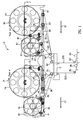
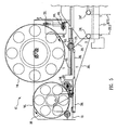
- FIG. 1 An exemplary embodiment of a graphite tape supply and backing paper take-up apparatus 10 in accordance with the present disclosure is illustrated in the partial elevation view of Fig. 1 .
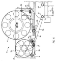
- Fig. 2 is a cross-sectional view of the exemplary apparatus 10, as seen along the lines of the section 2-2 taken in Fig. 1 .
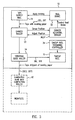
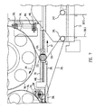
- Fig. 3 is a functional block diagram of an exemplary tape supply and backing paper take-up portion of the apparatus of Figs. 1 and 2 .
- the exemplary apparatus 10 comprises a pair of graphite tape supply reels 14L and 14T and an associated pair of backing paper take-up reels 16L and 16T, which may be mounted on a support frame 18 of the laminating machine for independent rotation in the direction of the arrows DR respectively associated with each reel 14L, 14T, 16L and 16T during the tape laminating process.
- the laminating machine (not illustrated), including the tape laminating head 12 thereof, may move in the direction of the arrows DT in Fig. 1 , i.e ., to the left of the figure, relative to a work piece (not illustrated) located below the laminating head 12.
- strands, or "tows” of graphite tape 20L and 20T having backing papers 30L and 30T respectively adhered to them are pulled off the respective supply reels 14L and 14T, pass over respective "dancer” rollers 22L and 22T, then over respective "stripping" rollers 24L and 24T.
- the respective backing papers 30L and 30T are stripped off the respective strands 20L and 20T and are respectively wound onto the take-up reels 16L and 16T.
- the strands 20LS and 20TS i.e ., the graphite tapes stripped of their respective backing papers 30L and 30T, then pass over respective guide rollers 26L and 26T, and thence, below respective compaction rollers 28L and 28T in the laminating head 12.
- the compaction rollers 28L and 28T of the laminating head 12 respectively press a sticky side S of a respective one of the strands of tape down onto the surface of the work piece as the laminating head 12 of the machine passes over it in the direction of the arrows DT.
- the respective strands of tape 20LS and 20TS may be cut "on-the-fly," i.e ., while the laminating machine is still moving.
- the laminating machine may be raised up relative to the work piece, rotated horizontally through a selected angle, e.g ., 45°, 90°, 135°, 180°, to name a few, and lowered back down to the work piece.
- a next pass may then be made by the machine over the work piece in another direction, for example, in the opposite direction to the first pass, i.e., to the right in Fig. 1 .
- the supply and backing paper take-up reels 14L and 16L and other associated components located to the left of the laminating head 12 in the figure always “lead” the laminating head 12 when laying tape, and hence, are referred to herein as “leading” components of the apparatus 10, whereas, the components to the right of the laminating head 12 always “trail” the head, and are therefore referred to as the “trailing" components of the apparatus.
- the trailing components 14T, 16T, 20T, 22T, 24T, 26T and 28T of the apparatus 10 may be offset transversely to the direction of movement DT of the laminating machine relative to the leading components of the apparatus at a pitch equal to the width of a corresponding one of the tapes 20L and 20T.
- the laminating machine may lay multiple strands of tape 20LS and 20TS onto the work piece simultaneously in a single pass, or swath. Further, as illustrated in Fig.
- the laminating machine may comprise additional sets of both leading and trailing tape supply and backing paper take up components 14L, 16L, 22L, 24L, 26L and 28L and 14T, 16T, 22T, 24T, 26T and 28T that extend transversely at similar intervals, or pitches.
- the apparatus 10 may comprise five such additional sets 14L, 16L, 22L, 24L, 26L and 28L and 14T, 16T, 22T, 24T, 26T and 28T, such that the laminating machine is capable of laying 12 parallel, abutting strips, or swaths, of tape 20LS and 20TS onto the work piece simultaneously in a single pass of the machine over the work piece.
- the graphite tape 20 employed with the laminating machine may comprise a matrix of unidirectional graphite fibers embedded within, or impregnated with, an uncured resin, of a type sometimes referred to a "prepreg." Since the resin is not cured, it is tacky, or sticky to the touch. To keep it tacky, and for ease of handling, the tape is manufactured with a liner of the backing paper 30 adhered to one side thereof.
- the backing paper 30 incorporates a release agent on its opposite surfaces that is different in strength, i.e ., the releasing ability is stronger on one side of the backing paper than on the other. This difference in strength of adhesion with the graphite tape 20 is provided so that the tape can be single-wound onto a supply reel.
- the tape may then be stripped off the reel easily, i.e ., without adhering to the next inward layer of tape, but with the backing paper still adhering to one side of the graphite tape, referred to herein as the "sticky" side of the tape.
- the backing paper may remain adhered until just prior to the application of the tape to the work piece to maximize the adhesive properties of the sticky side of the tape.
- each supply reel 14L and 14T of the apparatus 10 is provided with an associated backing paper take-up reel 16L and 16T, respectively, disposed adjacent thereto.
- the supply reels 14L and 14T are respectively loaded with graphite tapes 20L and 20T, each having respective, protective backing papers 30L and 30T adhering thereto, and the loaded supply reels 14L and 14T, along with the respective backing paper take-up reels 16L and 16T, are mounted on the laminating machine.
- the respective outer ends of the tapes 20L and 20T are threaded around the respective dancer rollers 22L and 22T, and then around the respective stripping rollers 24L and 24T.
- the respective backing papers 30L and 30T are then stripped away from their respective tapes 20L and 20T at the stripping rollers 24L and 24T.
- the respective outer ends of the backing papers are then coupled to the cores of the respective backing paper take-up reels.
- the outer ends of the tapes 20LS and 20TS i.e., the graphite tapes that have been stripped of their respective backing papers, are threaded over respective guide rollers 26L and 26T, and then below their respective compaction rollers 28L and 28T in the laminating head 12.
- the stripping rollers 24L and 24T are arranged such that the movements of the respective tapes 20L and 20T and their adherent backing papers 30L and 30T over the stripping rollers 24L and 24T may cause the respective tapes and backing papers to move in different directions.
- the tapes and their respective backing papers are pulled apart from one another at the respective stripping rollers 24L and 24T.
- This change in relative movement between the tapes and their respective backing papers imparts tension forces that can act on the plane of adhesion between the tapes and their respective backing papers and thereby strip the backing papers from their respective tapes for subsequent winding onto the respective backing paper take-up reels 16L and 16T.
- the tapes 20L and 20T are pulled off their respective supply reels 14L and 14T, pass over the respective dancer rollers 22L and 22T, and then over the respective stripping rollers 24L and 24T.
- the respective backing papers 30L and 30T are stripped from the respective tape strands and then spooled onto the backing paper take-up reels 16L and 16T of the apparatus, as illustrated in Fig. 1 .
- the graphite tape strands 20LS and 20TS then pass respectively onto the corresponding guide and compaction rollers 26L, 26T and 28L and 28T that follow.
- the sticky sides of the tapes (indicated by the S's in the figures), which were formerly protected by the backing papers 30L and 30T, are now appropriately exposed and disposed for application to the work piece by the respective compaction rollers 28L and 28T.
- the laminating process includes two steps S4 and S5. These steps may involve relatively sharp accelerations and decelerations of the graphite tape, and hence, the associated respective tape-supply and backing-paper take-up reels 14L, 14T and 16L, 16T. These steps may be referred to as a tape "add” step S4 and a tape "cut” step S5.
- the laminating head 12 of the laminating machine, and in particular, the compaction rollers 28L and 28T are translated a short distance above the work piece.
- the end of the tapes 20LS and 20TS may be disposed a short distance from the compaction rollers 28L and 28T.
- the tape feed may begin just prior to lowering the head when the end of the tape may be vertically aligned with a first location on the work piece, e.g ., an edge thereof, at which the beginning of a pass may take place.
- the compaction rollers 28L and 28T may then lowered onto the work piece such that the compaction rollers tack the sticky side of the respective ends of the tapes 20LS and 20TS to the work piece.
- the adds are done "on-the-fly," that is, while the laminating machine and head 12 are moving relative to the work piece.
- the machine including the tape supply apparatus 10, may then translate over the work piece in the direction DT of the arrows in Fig. 1 at a high rate of speed, such that the compaction rollers press the sticky sides "S" of the multiple strands of tape 20LS and 20TS onto the work piece, causing the tape strands to adhere to it.
- the tapes 20L and 20T may be forcefully stripped off the respective supply reels 14L and 14T very rapidly by the movement of the machine across the work piece, i.e ., may be forcefully accelerated, along with the supply reels 14L and 14T, and accordingly, the tension in the tapes may need to be accurately controlled in order to prevent the rollers of the laminating head 12 from skidding on the tapes, causing damage, or adversely impacting the accuracy of the add. Because the adds are done on-the-fly ( i.e ., the laminating machine does not pause over the work piece at the add locations), the timing of the add and the tension in the tapes may need to be controlled very consistently.
- the end of the pass may occur when the compaction rollers 28L and 28T pass over a second location on the work piece, for example, an opposite, second edge thereof.
- the tape add step may terminate, and the cut process S5 may commence.
- respective knives (not illustrated) may quickly sever the tapes 20LS and 20TS on-the-fly, i.e., while the tapes are still moving, and coincident with the second location on the work piece.
- the tapes 20LS and 20TS, and hence, the respective supply reels 14L and 14T may be decelerated very rapidly. As above, the respective tensions in the tapes 20LS and 20TS may therefore need to be carefully managed to prevent undesirable consequences.
- the exemplary apparatus 10 described herein may be adapted to provide such precise control.
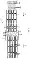
- the apparatus may use an unprecedented 38 mm (1.5 inch) wide graphite tape 20 wound onto the supply reels 14L and 14T, it is not limited to those widths, but may also be used advantageously for other tape widths, as well.
- the apparatus 10 of the present disclosure may thus be particularly suited for supplying the large quantities of material needed for high speed lamination.
- contoured parts wide swaths of material composed of a number of narrow strips may be laid in a single pass, as discussed above. This process is referred to herein as "fiber placement."
- fiber placement One of the difficulties with fiber placement experienced by conventional laminating apparatus may be in controlling the numerous individual tape supplies. Particularly, in maintaining the appropriate tension in the tapes during laminating so as to avoid tape bridging at sharp contours during adds, tape overruns at cuts and/or other undesirable situations.
- the apparatus 10 may supply consistently oriented graphite tapes 20L and 20T from respective supply reels 14L and 14T.
- the apparatus may remove and collect the respective backing papers 30L and 30T on respective separate take-up reels 16L and 16T.
- the apparatus may have actively controlled dancer rollers 22L and 22T, supply reel braking systems 32L and 32T and backing paper take-up reel tensioners 34L and 34T that may be adapted to precisely manage tape tension and reel inertia in the manner described below.
- the apparatus may thus provide a reliable means for supplying multiple swaths of relatively wide graphite tapes 20 to a laminating machine that employs high-speed, on-the-fly tape course adds and cuts.
- the apparatus 10 may use a simple on/off active control to manage the movement of the dancers 22L and 22T and to provide an appropriate braking of the supply reels 14L and 14T that may be independent of lamination speed or reel inertia.
- the tape supply spools that are used by existing solutions may also increase material costs.
- the graphite tape, or "slit material” is first removed from the backing paper, and a thin plastic "replacement" backing film is then re-applied to the tape prior to winding it onto the spool cores.
- the apparatus 10 of the present disclosure uses tape 20L, 20T to which the original backing paper 30 is still attached, thereby obviating the need for replacement backing films.
- the apparatus 10 may be designed to accept large, single wound supply reels 14L, 14T that are wound with relatively wide tapes 20L, 20T, i.e., tapes having a width that is three times or greater than the 13 mm (0.5 in.) wide tapes to which the prior art tape supply apparatuses are limited.
- the respective dancers 22L and 22T may be mounted in respective linear guides 40L and 40T on the support frame 18.
- Respective pneumatic actuators 36L and 36T may supply respective forces to the dancers 22L and 22T through respective pushrods 38L and 38T.
- a simple on/off control may change the force applied to the respective dancers 22L and 22T from a low value to a high value.
- This simple, active control mechanism ensures that the respective supply reels 14L and 14T stop without creating slack in the tapes 20L and 20T during an on-the-fly cut, and that the dancers 22L and 22T may be in the optimum position for an on-the-fly add.
- Properly positioned dancers ensure that adds may be accomplished without causing excessively high tension in the tapes, which may result in tape damage or course start inaccuracies, and that cuts may be accomplished without tape overrun.
- the pneumatic dancer actuation cylinders 36L and 36T, backing paper take-up spool tensioners 34L and 34T, and the braking forces applied to the supply reels 14L and 14T by the respective reel brakes 32L and 32T may combine to keep the tension in the tapes 20LS and 20TS at the respective compaction rollers 28L and 28T low and consistent. Excessive tension at the compaction rollers 28L and 28T can also cause bridging at step changes in the contour of the work piece forming tool (not illustrated).
- the apparatus 10 may also support all-sticky-side-down lamination.
- the side "S" of the graphite tape 20 that is adhered to the backing paper 30 may exhibit significantly more tack than a side that has been exposed to air and light for any length of time. Testing of the apparatus 10 has demonstrated that laminating performance may be improved if all the tapes are facing in one direction, in other words, with the sticky side "S" facing down.
- the exemplary configuration illustrated in Figs. 1 and 2 may enable the laminating machine to place all graphite tapes of a swath with the sticky side down.
- the leading supply reel 14L may be single wound with the backing paper 30L facing in ("paper in”), and the trailing reel 14T may be single wound with the backing paper 30T facing out (“paper out”).
- the backing paper take-up reels 16L and 16T may instead be respectively positioned as illustrated in Fig. 1 so as to take up the backing papers 30L and 30T respectively facing in and out, as the respective tapes 20L and 20T feed toward the laminating machine.
- the apparatus 10 of this disclosure may provide the active control needed to use large, high-inertia supply reels 14L and 14T that may be single-wound with a relatively wide tape.
- the existing solutions may be limited to using level-wound spools of 13 mm (0.5 inch) wide tape.
- the apparatus 10 may thus provide an essential element of a laminating system that may exhibit lower material costs and substantially higher lamination rates.
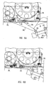
- Fig. 5 is an enlarged partial elevation view of a portion of the apparatus 10, showing only the leading supply reel 14L and associated take-up spool 16L thereof during a steady state tape laminating operation.
- the tape 20L is first re-directed around the dancer roller 22L before heading into the laminating head 12 of the laminating machine.
- the tension in the tape 20L may produce a force on the dancer carriage 42L that is directed toward the right of the figure.
- the pneumatic cylinder 36L may produce a force on the carriage 42L that is directed to the left and that may only partially balance the tape tension force.
- a pneumatic actuating cylinder 44L coupled to a brake lever 46L so as to selectively apply a high braking force to the rim of the supply reel 14T may be deactivated, which may cause an integral compression spring of the brake lever to produce a low, substantially constant braking force on the supply reel.
- the braking force may create a controlled tension in the moving tape 20L.
- the tape tension in turn, may hold the dancer roller 22L in a fully extended position, as illustrated in Fig. 5 .
- the backing paper 30L is peeled away from the tape 20L.
- the backing paper 30L may absorb some of the tension that was in the tape 20L upstream of the roller 24L, and the remaining, controlled tension in the tape 20LS extends down to the compaction roller 28L (not seen in Fig. 5 ).
- Fig. 6 is an enlarged partial elevation view of the leading supply and backing paper take-up reels 14L and 16L portion of the apparatus 10 of Fig. 5 , shown immediately after a cut operation S5 and poised for an add operation.
- the pneumatic dancer actuating cylinder 36L may be switched to a higher retraction force, which may cause the actuating rod 38L of the actuator to retract the dancer carriage 42L, and hence, the dancer 22L, to the left, relative to the support frame 18, as illustrated in Fig. 6 .
- This movement of the dancer 22L may take up the slack in the tape 20L as the supply reel 14L decelerates due to the constant drag force acting thereon by the reel brake 32L described above.
- a signal generated by a sensor 37 located in the pneumatic actuator 36L and adapted to sense the position of the dancer 22L relative to the actuator 36L may be used to actuate the high-force pneumatic braking cylinder 44L described above, which quickly stops the supply reel 14L from rotating.
- Fig. 7 is an enlarged partial elevation view of the leading supply and backing paper take-up reels 14L and 16L portion of the apparatus 10 of Fig. 5 , shown during an add operation.
- the force provided by the pneumatic actuation cylinder 36L on the dancer 22L may be reduced to the low setting.
- the tension in the tape 20L may then move the dancer 22L to the right, as indicated by the large arrow DT in Fig. 7 .
- Providing a minimum tension in the tape 20L during an add may improve the accuracy and consistency of the starting point.
- Figs. 8A and 8B are enlarged partial elevation views of the leading supply and backing paper take-up reels 14L and 16L portion of the apparatus 10 of Fig. 5 after a cut operation S5, at which the supply reel 24L may be braked against rotation. While laminating material on a work piece and during repositioning moves, the head 12 of the laminating machine may rock down, as shown in Fig. 8A , or up, as shown in Fig. 8B . After a cut S5, the reel brake 32L prevents rotation of the supply reel 14L.
- the dancer 22L may move appropriately to maintain constant tape tension constant during the rocking movement of the laminating head 12.
- rotation of the head 12 during lamination may affect the pay-out velocity of the tape 20L.
- Rotation of the head 12 when the supply reel 14L is stationary may cause the dancer 22L to move. Accordingly, the dancer 22L may not be retracted fully during the cut so that it may take up any slack in the tape immediately after the cut.
- the apparatus 10 may provide an important feature of a high-speed tape laminating machine.
- Current spool-based machines using level wound tape with widths of 13 mm (0.5 inches) cannot achieve lamination rates as high as machines equipped with large supply reels single-wound with wider tapes.
- the apparatus 10 may help move tape lamination technology to a higher level that reduces the costs of tooling, facilities, materials and equipment.
- exemplary method 900 may include specification and design 904 of the aircraft 902 and material procurement 906.
- component and subassembly manufacturing 908 and system integration 910 of the aircraft 902 takes place.
- the aircraft 902 may go through certification and delivery 912 in order to be placed in service 914.
- routine maintenance and service 916 which may also include modification, reconfiguration, refurbishment, and so on).
- Each of the processes of method 900 may be performed or carried out by a system integrator, a third party, and/or an operator (e.g ., a customer).
- a system integrator may include without limitation any number of aircraft manufacturers and major-system subcontractors
- a third party may include without limitation any number of venders, subcontractors, and suppliers
- an operator may be an airline, leasing company, military entity, service organization, and so on.
- the aircraft 902 produced by exemplary method 900 may include an airframe 918 with a plurality of systems 920 and an interior 922.
- high-level systems 920 include one or more of a propulsion system 924, an electrical system 926, a hydraulic system 928, and an environmental system 930. Any number of other systems may be included.
- an aerospace example is shown, the principles of the invention may be applied to other industries, such as the automotive industry.
- Apparatus and methods embodied herein may be employed during any one or more of the stages of the production and service method 900.
- components or subassemblies corresponding to production process 908 may be fabricated or manufactured in a manner similar to components or subassemblies produced while the aircraft 902 is in service.
- one or more apparatus embodiments, method embodiments, or a combination thereof may be utilized during the production stages 908 and 910, for example, by substantially expediting assembly of or reducing the cost of an aircraft 902.
- apparatus embodiments, method embodiments, or a combination thereof may be utilized while the aircraft 902 is in service, for example and without limitation, to maintenance and service 916.
Description
- This disclosure generally relates to tools used in the manufacture of composite structures, and in particular, to a graphite composite tape supply and backing paper take-up apparatus for use in conjunction with a high speed, composite tape laminating machine that enables the use of larger tape supply reels and substantially wider tapes, thereby achieving higher lamination rates and lower material costs in the lamination process.
- The demand for large, complex composite parts, such as are used, for example, in composite air frames, is growing rapidly. These parts are typically produced by laying parallel strips of a composite tape, e.g., unidirectional graphite fiber tape impregnated with an uncured resin (a "prepreg"), immediately adjacent to each other on a forming tool, then curing the resin. The growing demand is typically being satisfied by suppliers in one of two ways: 1) by purchasing multiple, current-technology laminating machines, or 2) by developing machines that can laminate parts at a higher rate. The second option, developing high speed laminating machines, can, in the long run, actually reduce tooling, facility, and equipment costs.
- Existing tape supply solutions all rely on a relatively narrow tape that is "level wound" onto long spools, i.e., in the same manner as a line is wound onto a fishing reel equipped with a reciprocating pawl. In order to level-wind the material, the tape width is limited to 13 mm (0.5 inch). The narrow tapes cannot be "single-wound:' i.e., in the manner of a movie film, onto reels of a corresponding width because the diameter of the reels would have to be increased substantially to accommodate a useful amount of tape thereon, and hence, would have an unacceptably high inertia.
- A "dancer," i.e., a secondary roller disposed adjacent to the spool and over which the tape unspools, is commonly used to absorb the shock applied to the tape by accelerating the spool, and a brake acting on the spool is used absorb the inertia of the spool when decelerating the spool. The existing solutions use active control of the braking force applied to the supply spool, and passive control of dancer movement. Because the existing solutions do not actively control the dancer position, they have great difficulty controlling large supply reels with varying inertias.
- Thus, the existing solutions are limited to the use of spools that are level-wound with laminating tape that is limited to a maximum width of 13 mm (0.5 inch). The total number of tape strips that a laminating machine can manage when laying a swath of tape is limited, and using a narrow tape creates a relatively small total swath width, thereby requiring a large number of passes of the laminating head of the machine over the layup tool to laminate a part having a relatively large area. Therefore, higher lamination rates could be achieved if multiple strips of wider strips of tape could be used reliably.
- Accordingly, there is a need in the industry for an apparatus that enables a composite tape laminating machine to lay multiple tapes having greater widths reliably, and thereby achieve a substantially increased laminating speed.
- Background art is provided in
EP 1 859 917 A2US 5 480 508 A . -
EP 1 859 917 A2claims -
US 5 480 508 A discloses a process in which a prepreg tape is firstly prepared by bonding a prepreg layer to a backing paper and then the prepreg tape is cut to a depth enough to cut the prepreg tape but not the backing paper. An unnecessary portion of the prepreg tape is removed from the backing paper to obtain a cut prepreg tape. A laminating attachment is moved in a predetermined direction while urging the prepreg tape against the surface of an operating table. The cut prepreg tape is peeled off from the backing paper and the peeled off prepreg tape is bonded to the operating table. - The present invention is an apparatus as defined in
Claim 1 of the appended claims, and a method as defined inClaim 10. - In accordance with the present disclosure, a graphite composite tape supply and backing paper take-up apparatus is provided for use in conjunction with a composite tape laminating machine that enables substantially larger tape supply reels and substantially wider tapes to be used on the machine reliably, thereby achieving higher laminating rates and lower material costs in the lamination process.
- In one exemplary embodiment, an apparatus comprises a rotatably mounted supply reel, a rotatably mounted take-up reel disposed adjacent to the supply reel, a dancer roller mounted for lateral movement relative to the supply and take-up reels, a rotatable compaction roller adapted for rolling movement over a surface of a work piece, and a rotatably mounted stripping roller disposed between the dancer roller and the laminating head. A tape comprising first and second strands adhered to each other is wound onto the supply reel. The first strand has an outer end extending from the supply reel, around the dancer roller and the stripping roller and below the compaction roller. The second strand has an outer end extending from the supply reel, around the dancer roller and the stripping roller and coupled to a core of the take-up reel. A mechanism is provided that actively controls the rotation of the supply and take-up reels and the lateral movement of the dancer roller such that tension in at least the first strand is maintained substantially constant during the movement of the compaction roller over the surface of the work piece and a subsequent cutting of the first strand.
- In another exemplary embodiment, a method comprises providing a rotatably mounted supply reel having a tape comprising first and second strands adhered to each other wound thereon; mounting a rotatably mounted take-up reel adjacent to the supply reel; mounting a dancer roller for lateral movement relative to the supply and take-up reels; mounting a rotatable compaction roller for rolling movement over a surface of a work piece; mounting a rotatable stripping roller between the dancer roller and the compaction roller; extending an outer end of the first strand from the supply reel, around the dancer roller and the stripping roller and below the compaction roller; extending an outer end of the second strand from the supply reel, around the dancer roller and the stripping roller and coupling it to a core of the take-up reel; rolling the compaction roller over the surface of the work piece such that a sticky side of the first strand is adhered to the work piece surface; cutting the second strand during the movement of the compaction roller; and, actively controlling the rotation of the supply and take-up reels and the lateral movement of the dancer roller such that tension in at least the first strand is maintained substantially constant during the movement of the compaction roller over the surface of the work piece and a subsequent cutting of the first strand.
- Further embodiments provide an apparatus, comprising:
- a supply reel;
- a take-up reel disposed adjacent to the supply reel;
- a dancer roller mounted for lateral movement relative to the supply and take-up reels;
- a compaction roller adapted for rolling movement over a surface of a work piece;
- a stripping roller disposed between the dancer roller and the laminating head;
- a tape comprising first and second strands adhered to each other and wound onto the supply reel, the first strand having an outer end extending from the supply reel, around the dancer roller and the stripping roller and below the compaction roller, the second strand having an outer end extending from the supply reel, around the dancer roller and the stripping roller and coupled to a core of the take-up reel; and,
- a mechanism for actively controlling the rotation of the supply and take-up reels and the lateral movement of the dancer roller such that tension in at least the first strand is maintained substantially constant during the movement of the compaction roller over the surface of the work piece and a subsequent cutting of the first strand.
- Optionally, the tape is single-wound on the supply reel.
- Optionally, the second strand is coated with a release agent on opposite sides thereof, and wherein the release property of the release agent on one side is stronger than the release property of the release agent on the other side.
- Optionally, the first strand comprises a matrix of graphite fibers impregnated with an uncured resin.
- Optionally, the apparatus supplies the first strand to the laminating head with an adhering side thereof facing toward the work piece.
- Optionally, the first strand tension control mechanism comprises:
- a sensor for sensing the lateral position of the dancer roller and for generating a signal corresponding to said position;
- an actuator coupled to the dancer roller and operative to move the dancer roller laterally in response to the signal generated by the sensor;
- a brake acting on the supply reel and operative to brake rotation of the supply reel in response to the signal generated by the sensor; and,
- a tensioner acting on the take-up reel and operative to maintain tension in the second strand substantially constant.
- Optionally, the sensor comprises a proximity sensor located in the actuator.
- Optionally, the actuator comprises a pneumatic actuator.
- Optionally, the apparatus is disposed on the support frame so as to lead the compaction roller during movement thereof across the surface of the work piece, and further comprising:
- a second apparatus disposed adjacent to the first apparatus so as to trail the compaction roller during movement thereof across the surface of the work piece and being offset transversely from the leading apparatus by the width of the first strand.
- Yet further embodiments provide a tape laminating machine for aircraft fabrication equipped with the apparatus described or a tape laminating machine equipped with the apparatus as described above.
- Yet further embodiments provide a method for supplying a tape comprising first and second strands to a laminating machine during a lamination of the second strand to a work piece, the method comprising:
- mounting the apparatus of
claim 1 on a support frame of the laminating machine - supplying the tape from the supply reel to a laminating head of the laminating machine;
- stripping the second strand from the tape before it reaches the laminating head;
- taking up the second strand with the take-up reel after it is stripped from the tape;
- rolling the compaction roller over the surface of the work piece such that a sticky side of the first strand is adhered to the surface;
- cutting the second strand during the movement of the compaction roller, and,
- controlling the rotation of the supply and take-up reels and the lateral movement of the dancer roller relative to the support frame such that the tension in the at least first strand is maintained substantially constant during the movement of the compaction roller over the surface of the work piece and the subsequent cutting of the first strand.
- Yet further embodiments provide a method, comprising:
- providing a rotatably mounted supply reel having a tape comprising first and second strands adhered to each other wound thereon;
- mounting a rotatable take-up reel adjacent to the supply reel;
- mounting a rotatable dancer roller for lateral movement relative to the supply and take-up reels;
- mounting a rotatable compaction roller for rolling movement over a surface of a work piece;
- mounting a rotatable stripping roller between the dancer roller and the compaction roller;
- extending an outer end of the first strand from the supply reel, around the dancer roller and the stripping roller and below the compaction roller;
- extending an outer end of the second strand from the supply reel, around the dancer roller and the stripping roller and coupling it to a core of the take-up reel;
- rolling the compaction roller over the surface of the work piece such that a sticky side of the first strand is adhered to the surface;
- cutting the second strand during the movement of the compaction roller and,
- actively controlling the rotation of the supply and take-up reels and the lateral movement of the dancer roller such that tension in at least the first strand is maintained substantially constant during the movement of the compaction roller over the surface of the work piece and a subsequent cutting of the first strand.
- Optionally, the rolling of the compaction roller comprises:
- tacking the outer end of the first strand to a first location on the work piece with the compaction roller;
- rolling the compaction roller over the surface of the work piece so as to strip the tape off of the supply reel; and,
- pressing the adhering side of the tape onto the surface of the work piece with the compaction roller during the movement of the compaction roller over the work piece.
- Optionally, the cutting of the first strand comprises cutting the first strand at a second location on the work piece.
- Optionally, the tape is single-wound onto the supply reel.
- Optionally, the pressing of the sticky side of the first strand to the surface of the work piece comprises supplying the tape to the compaction roller with the sticky side facing toward the surface of the work piece.
- Optionally, the controlling of the rotation of the supply and take-up reels and the lateral movement of the dancer roller comprises:
- sensing the lateral position of the dancer roller and generating a signal corresponding to said position;
- moving the dancer roller laterally in response to the signal;
- braking rotation of the supply reel in response to the signal; and,
- rotating the take-up reel so as to maintain tension in the second strand substantially constant after it is stripped from the tape.
- Yet further embodiments provide an apparatus for supplying graphite tape to a high speed graphite tape laminating machine, the apparatus comprising:
- a tape supply reel rotatably mounted on a support frame of the laminating machine;
- a backing paper take-up reel rotatably mounted on the support frame adjacent to the tape supply reel;
- a dancer roller mounted for lateral movement on the support frame;
- a stripping roller rotatably mounted between the dancer roller and a laminating head;
- a strand of graphite tape level-wound onto the supply reel,
the tape having a paper backing adhering to a sticky side thereof and an outer end extending from the supply reel, around the dancer roller and the stripping roller and to a laminating head of the laminating machine,
the paper backing having an outer end extending from the supply reel, around the dancer roller and the stripping roller and connected to a core of the take-up reel, and
wherein the stripping roller is arranged such that movement of the tape and backing paper over the stripping roller causes the tape and backing paper to move in different directions, thereby imparting a tension force on a plane of adhesion between the tape and backing paper and stripping the backing paper from the tape for winding onto the take-up reel; and, - a mechanism for actively controlling the rotation of the tape supply and backing paper take-up reels and the lateral movement of the dancer roller relative to the support frame such that tension in the tape is maintained substantially constant during both a tape add operation and a tape cut operation of the laminating machine.
- Optionally, the apparatus is disposed on the support frame so as to lead the laminating head during movement of the laminating head across a surface of a work piece, and further comprising:
- a second apparatus disposed adjacent to the first apparatus so as to trail the compaction roller during movement thereof across the surface of the work piece and being offset transversely from the leading apparatus by the width of the first strand.
- Optionally, the apparatus further comprises a plurality of leading and lagging apparatuses respectively offset transversely from each other such that the laminating machine is capable of simultaneously laminating a plurality of parallel, transversely abutting graphite tapes onto the surface of the work piece in a single pass of the compaction rollers over the surface.
- Yet further embodiments provide a method for supplying graphite tape to a laminating machine and for taking up a backing paper adhered to a sticky side of the tape during lamination of the tape to a surface of a work piece, the method comprising:
- mounting a rotatable tape supply reel on a support frame of the laminating machine;
- mounting a rotatable backing paper take-up reel on the support frame adjacent to the tape supply reel;
- mounting a dancer roller on the support frame for lateral movement relative thereto;
- single-winding a strand of the tape with the backing paper adhered thereto onto the supply reel;
- extending an outer end of the tape from the supply reel, around the dancer roller and below a compaction roller of the laminating machine;
- mounting a rotatable stripping roller between the dancer roller and the compaction roller such that movement of the tape and backing paper over the stripping roller causes the tape and backing paper to move in different directions, thereby imparting a tension force on a plane of adhesion between the tape and backing paper and stripping the backing paper from the tape for winding onto the take-up reel;
- stripping the backing paper from the tape with the stripping roller before the tape reaches the laminating head;
- winding the backing paper onto take-up reel;
- tacking the sticky side of the outer end of the tape to a first location on the surface of the work piece with the compaction roller;
- rolling the compaction roller over the surface of the work piece so as to pull the tape off of the supply reel;
- pressing the sticky side of the tape onto the surface of the work piece with the compaction roller during the movement of the compaction roller over the work piece;
- cutting the tape at a second location on the surface of the work piece and during the movement of the compaction roller; and,
- actively controlling the rotation of the tape supply and backing paper take-up reels and the lateral movement of the dancer roller relative to the support frame such that tension in the tape is maintained substantially constant during both the tape add operation and the tape cut operation of the laminating machine.
- Optionally, the laminating machine further comprises first and second pluralities of the tape supply and backing paper take-up reels, dancer rollers, stripping rollers and compaction rollers respectively offset transversely from each other by the width of the tape and respectively disposed so as to lead and trail the compaction rollers, and the method further comprises:
- laminating a plurality of parallel, transversely abutting graphite tapes onto the surface of the work piece in a single pass of the compaction rollers over the surface.
- A better understanding of the above and many other features and advantages of the apparatus of the present disclosure can be obtained from a consideration of the detailed description of an exemplary embodiment thereof below, particular if such consideration is made in conjunction with the appended drawings, wherein like reference numbers are used to refer to like elements in the respective figures thereof.
-
-
Fig. 1 is a partial elevation view of an exemplary embodiment of a graphite tape supply and backing paper take-up apparatus in accordance with the present disclosure, shown mounted on a graphite tape laminating machine and adjacent to the laminating head thereof; -
Fig. 2 is top plan cross-sectional view of the exemplary apparatus ofFig. 1 , as seen along a section line extending through the respective centers of leading and trailing tape supply and backing paper take-up reels of the apparatus; -
Fig. 3 is a functional block diagram of an exemplary tape supply and backing paper take-up portion of the exemplary apparatus ofFig. 1 ; -
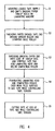
Fig. 4 is a process flow diagram showing successive steps in an exemplary embodiment of a method for supplying graphite tape to a tape laminating machine during a laminating process in accordance with the present disclosure; -
Fig. 5 is an enlarged partial elevation view of a leading supply reel and associated take up reel of the exemplary apparatus, shown during a steady state tape laminating operation; -
Fig. 6 is another enlarged partial elevation view of the supply and take up reels ofFig. 5 , shown immediately after a "cut" operation and prior to an "add" operation; -
Fig. 7 is another enlarged partial elevation view of the leading supply and take up reels, shown during an add operation; -
Figs. 8A and 8B are enlarged partial elevation views of the leading supply and take-up reels ofFig. 5 , showing movement of a dancer of the apparatus after a cut operation; -
Fig. 9 is a flow diagram of aircraft production and service methodology; and -
Fig. 10 is a block diagram of an aircraft. - An exemplary embodiment of a graphite tape supply and backing paper take-up
apparatus 10 in accordance with the present disclosure is illustrated in the partial elevation view ofFig. 1 .Fig. 2 is a cross-sectional view of theexemplary apparatus 10, as seen along the lines of the section 2-2 taken inFig. 1 .Fig. 3 is a functional block diagram of an exemplary tape supply and backing paper take-up portion of the apparatus ofFigs. 1 and2 . - As may be seen by reference to
Figs. 1-3 , theexemplary apparatus 10 comprises a pair of graphitetape supply reels reels support frame 18 of the laminating machine for independent rotation in the direction of the arrows DR respectively associated with eachreel - During the laminating process, the laminating machine (not illustrated), including the
tape laminating head 12 thereof, may move in the direction of the arrows DT inFig. 1 , i.e., to the left of the figure, relative to a work piece (not illustrated) located below the laminatinghead 12. During this movement, strands, or "tows," ofgraphite tape backing papers respective supply reels rollers rollers respective strands rollers respective backing papers respective strands reels respective backing papers respective guide rollers respective compaction rollers laminating head 12. Thecompaction rollers laminating head 12 respectively press a sticky side S of a respective one of the strands of tape down onto the surface of the work piece as the laminatinghead 12 of the machine passes over it in the direction of the arrows DT. - At the end of the pass of the
laminating head 12 over the work piece, the respective strands of tape 20LS and 20TS may be cut "on-the-fly," i.e., while the laminating machine is still moving. After the cutting operation, the laminating machine may be raised up relative to the work piece, rotated horizontally through a selected angle, e.g., 45°, 90°, 135°, 180°, to name a few, and lowered back down to the work piece. A next pass may then be made by the machine over the work piece in another direction, for example, in the opposite direction to the first pass, i.e., to the right inFig. 1 . - In the foregoing arrangement, the supply and backing paper take-up
reels laminating head 12 in the figure always "lead" thelaminating head 12 when laying tape, and hence, are referred to herein as "leading" components of theapparatus 10, whereas, the components to the right of thelaminating head 12 always "trail" the head, and are therefore referred to as the "trailing" components of the apparatus. - Additionally, as illustrated in the top plan cross-sectional view of
Fig. 2 , in the embodiment illustrated, the trailingcomponents apparatus 10 may be offset transversely to the direction of movement DT of the laminating machine relative to the leading components of the apparatus at a pitch equal to the width of a corresponding one of thetapes Fig. 2 , the laminating machine may comprise additional sets of both leading and trailing tape supply and backing paper take upcomponents apparatus 10 may comprise five suchadditional sets - The
graphite tape 20 employed with the laminating machine may comprise a matrix of unidirectional graphite fibers embedded within, or impregnated with, an uncured resin, of a type sometimes referred to a "prepreg." Since the resin is not cured, it is tacky, or sticky to the touch. To keep it tacky, and for ease of handling, the tape is manufactured with a liner of the backing paper 30 adhered to one side thereof. The backing paper 30 incorporates a release agent on its opposite surfaces that is different in strength, i.e., the releasing ability is stronger on one side of the backing paper than on the other. This difference in strength of adhesion with thegraphite tape 20 is provided so that the tape can be single-wound onto a supply reel. The tape may then be stripped off the reel easily, i.e., without adhering to the next inward layer of tape, but with the backing paper still adhering to one side of the graphite tape, referred to herein as the "sticky" side of the tape. The backing paper may remain adhered until just prior to the application of the tape to the work piece to maximize the adhesive properties of the sticky side of the tape. - Accordingly, it is necessary to remove and store the backing paper 30 prior to the application of the
tape 20 to the work piece. To store the backing paper after its removal, eachsupply reel apparatus 10 is provided with an associated backing paper take-upreel Fig. 1 and the process flow diagram ofFig. 4 , at S1, thesupply reels graphite tapes protective backing papers supply reels reels - At S2, the respective outer ends of the
tapes respective dancer rollers rollers respective backing papers respective tapes rollers respective guide rollers respective compaction rollers laminating head 12. - The stripping
rollers respective tapes adherent backing papers rollers rollers reels - Thus, during a laminating operation, the
tapes respective supply reels respective dancer rollers rollers respective backing papers reels Fig. 1 . The graphite tape strands 20LS and 20TS then pass respectively onto the corresponding guide andcompaction rollers backing papers respective compaction rollers - As illustrated in the process flow diagram of
Fig. 4 , the laminating process includes two steps S4 and S5. These steps may involve relatively sharp accelerations and decelerations of the graphite tape, and hence, the associated respective tape-supply and backing-paper take-upreels - In the add process S4, the laminating
head 12 of the laminating machine, and in particular, thecompaction rollers compaction rollers compaction rollers head 12 are moving relative to the work piece. The machine, including thetape supply apparatus 10, may then translate over the work piece in the direction DT of the arrows inFig. 1 at a high rate of speed, such that the compaction rollers press the sticky sides "S" of the multiple strands of tape 20LS and 20TS onto the work piece, causing the tape strands to adhere to it. During the add step, thetapes respective supply reels supply reels laminating head 12 from skidding on the tapes, causing damage, or adversely impacting the accuracy of the add. Because the adds are done on-the-fly (i.e., the laminating machine does not pause over the work piece at the add locations), the timing of the add and the tension in the tapes may need to be controlled very consistently. - The end of the pass may occur when the
compaction rollers respective supply reels - As those of skill in the art will appreciate, it may be necessary to maintain precise, accurate control over the tension in the graphite tapes 20LS and 20TS during both add and cut processes to obtain an accurate, reliable, high speed laminating process. The
exemplary apparatus 10 described herein may be adapted to provide such precise control. Also, although the apparatus may use an unprecedented 38 mm (1.5 inch)wide graphite tape 20 wound onto thesupply reels - The
apparatus 10 of the present disclosure may thus be particularly suited for supplying the large quantities of material needed for high speed lamination. When laminating contoured parts, wide swaths of material composed of a number of narrow strips may be laid in a single pass, as discussed above. This process is referred to herein as "fiber placement." One of the difficulties with fiber placement experienced by conventional laminating apparatus may be in controlling the numerous individual tape supplies. Particularly, in maintaining the appropriate tension in the tapes during laminating so as to avoid tape bridging at sharp contours during adds, tape overruns at cuts and/or other undesirable situations. Theapparatus 10 may supply consistently orientedgraphite tapes respective supply reels respective backing papers reels dancer rollers reel braking systems reel tensioners wide graphite tapes 20 to a laminating machine that employs high-speed, on-the-fly tape course adds and cuts. - The
apparatus 10 may use a simple on/off active control to manage the movement of thedancers supply reels apparatus 10 of the present disclosure usestape width supply reels apparatus 10 illustrated in, e.g.,Figs. 1 and2 herein. - As illustrated in
Fig. 1 , theapparatus 10 may be designed to accept large, singlewound supply reels wide tapes tape supply apparatus 10, therespective dancers linear guides support frame 18. Respectivepneumatic actuators dancers respective pushrods respective dancers respective supply reels tapes dancers - Thus, during steady state lamination, the pneumatic
dancer actuation cylinders spool tensioners supply reels respective reel brakes respective compaction rollers compaction rollers - The
apparatus 10 may also support all-sticky-side-down lamination. As discussed above, the side "S" of thegraphite tape 20 that is adhered to the backing paper 30 may exhibit significantly more tack than a side that has been exposed to air and light for any length of time. Testing of theapparatus 10 has demonstrated that laminating performance may be improved if all the tapes are facing in one direction, in other words, with the sticky side "S" facing down. As discussed above, the exemplary configuration illustrated inFigs. 1 and2 may enable the laminating machine to place all graphite tapes of a swath with the sticky side down. Accordingly, the leadingsupply reel 14L may be single wound with thebacking paper 30L facing in ("paper in"), and the trailingreel 14T may be single wound with thebacking paper 30T facing out ("paper out"). Instead of simply mirroring the position of the backing paper take-upreels Fig. 1 so as to take up thebacking papers respective tapes - Of importance, the
apparatus 10 of this disclosure may provide the active control needed to use large, high-inertia supply reels apparatus 10 may thus provide an essential element of a laminating system that may exhibit lower material costs and substantially higher lamination rates. -
Fig. 5 is an enlarged partial elevation view of a portion of theapparatus 10, showing only the leadingsupply reel 14L and associated take-upspool 16L thereof during a steady state tape laminating operation. As illustrated inFig. 5 , thetape 20L is first re-directed around thedancer roller 22L before heading into the laminatinghead 12 of the laminating machine. The tension in thetape 20L may produce a force on thedancer carriage 42L that is directed toward the right of the figure. Thepneumatic cylinder 36L may produce a force on thecarriage 42L that is directed to the left and that may only partially balance the tape tension force. During steady state lamination, apneumatic actuating cylinder 44L coupled to abrake lever 46L so as to selectively apply a high braking force to the rim of thesupply reel 14T may be deactivated, which may cause an integral compression spring of the brake lever to produce a low, substantially constant braking force on the supply reel. The braking force may create a controlled tension in the movingtape 20L. The tape tension, in turn, may hold thedancer roller 22L in a fully extended position, as illustrated inFig. 5 . As described above, as thetape 20L passes over the strippingroller 24L of the laminating machine, thebacking paper 30L is peeled away from thetape 20L. Thebacking paper 30L may absorb some of the tension that was in thetape 20L upstream of theroller 24L, and the remaining, controlled tension in the tape 20LS extends down to thecompaction roller 28L (not seen inFig. 5 ). -
Fig. 6 is an enlarged partial elevation view of the leading supply and backing paper take-upreels apparatus 10 ofFig. 5 , shown immediately after a cut operation S5 and poised for an add operation. When thetape 20L is cut, the pneumaticdancer actuating cylinder 36L may be switched to a higher retraction force, which may cause theactuating rod 38L of the actuator to retract thedancer carriage 42L, and hence, thedancer 22L, to the left, relative to thesupport frame 18, as illustrated inFig. 6 . This movement of thedancer 22L may take up the slack in thetape 20L as thesupply reel 14L decelerates due to the constant drag force acting thereon by thereel brake 32L described above. Once thecylinder 36L has retracted thedancer 22L by about 80% of its total travel, a signal generated by asensor 37 located in thepneumatic actuator 36L and adapted to sense the position of thedancer 22L relative to theactuator 36L may be used to actuate the high-forcepneumatic braking cylinder 44L described above, which quickly stops thesupply reel 14L from rotating. -
Fig. 7 is an enlarged partial elevation view of the leading supply and backing paper take-upreels apparatus 10 ofFig. 5 , shown during an add operation. At the beginning of the add, the force provided by thepneumatic actuation cylinder 36L on thedancer 22L may be reduced to the low setting. The tension in thetape 20L may then move thedancer 22L to the right, as indicated by the large arrow DT inFig. 7 . Providing a minimum tension in thetape 20L during an add may improve the accuracy and consistency of the starting point. -
Figs. 8A and 8B are enlarged partial elevation views of the leading supply and backing paper take-upreels apparatus 10 ofFig. 5 after a cut operation S5, at which thesupply reel 24L may be braked against rotation. While laminating material on a work piece and during repositioning moves, thehead 12 of the laminating machine may rock down, as shown inFig. 8A , or up, as shown inFig. 8B . After a cut S5, thereel brake 32L prevents rotation of thesupply reel 14L. Since the rocking movement of thehead 12 illustrated in the figures may change the length of tape between thesupply reel 14L and thehead 12, thedancer 22L may move appropriately to maintain constant tape tension constant during the rocking movement of thelaminating head 12. Thus, as respectively illustrated inFigs. 5A and 5B , rotation of thehead 12 during lamination may affect the pay-out velocity of thetape 20L. Rotation of thehead 12 when thesupply reel 14L is stationary may cause thedancer 22L to move. Accordingly, thedancer 22L may not be retracted fully during the cut so that it may take up any slack in the tape immediately after the cut. - In accordance with the exemplary embodiments described herein, the
apparatus 10 may provide an important feature of a high-speed tape laminating machine. Current spool-based machines using level wound tape with widths of 13 mm (0.5 inches) cannot achieve lamination rates as high as machines equipped with large supply reels single-wound with wider tapes. Accordingly, theapparatus 10 may help move tape lamination technology to a higher level that reduces the costs of tooling, facilities, materials and equipment. - Referring more particularly to the drawings, embodiments of the disclosure may be described in the context of an aircraft manufacturing and
service method 900 as shown inFig. 9 and anaircraft 902 as shown inFig. 10 . During pre-production,exemplary method 900 may include specification anddesign 904 of theaircraft 902 andmaterial procurement 906. During production, component andsubassembly manufacturing 908 andsystem integration 910 of theaircraft 902 takes place. Thereafter, theaircraft 902 may go through certification anddelivery 912 in order to be placed inservice 914. While in service by a customer, theaircraft 902 is scheduled for routine maintenance and service 916 (which may also include modification, reconfiguration, refurbishment, and so on). - Each of the processes of
method 900 may be performed or carried out by a system integrator, a third party, and/or an operator (e.g., a customer). For the purposes of this description, a system integrator may include without limitation any number of aircraft manufacturers and major-system subcontractors; a third party may include without limitation any number of venders, subcontractors, and suppliers; and an operator may be an airline, leasing company, military entity, service organization, and so on. - As shown in
Fig. 10 , theaircraft 902 produced byexemplary method 900 may include anairframe 918 with a plurality ofsystems 920 and an interior 922. Examples of high-level systems 920 include one or more of apropulsion system 924, anelectrical system 926, ahydraulic system 928, and anenvironmental system 930. Any number of other systems may be included. Although an aerospace example is shown, the principles of the invention may be applied to other industries, such as the automotive industry. - Apparatus and methods embodied herein may be employed during any one or more of the stages of the production and
service method 900. For example, components or subassemblies corresponding toproduction process 908 may be fabricated or manufactured in a manner similar to components or subassemblies produced while theaircraft 902 is in service. Also, one or more apparatus embodiments, method embodiments, or a combination thereof may be utilized during the production stages 908 and 910, for example, by substantially expediting assembly of or reducing the cost of anaircraft 902. Similarly, one or more of apparatus embodiments, method embodiments, or a combination thereof may be utilized while theaircraft 902 is in service, for example and without limitation, to maintenance andservice 916. - As those of skill in this art will appreciate, many modifications, substitutions and variations can be made in the applications and methods of implementation of the tape supply and backing paper take up apparatus of the present disclosure without departing from the scope of the invention as defined by the appended claims. In light of this, the scope of the present disclosure should not be limited to that of the particular embodiments illustrated and described herein, as they are only by way of some examples thereof, but instead, should be fully commensurate with that of the claims appended hereafter and their functional equivalents.
Claims (15)
- An apparatus (10), comprising:a supply reel (14L);a take-up reel (16L) disposed adjacent to the supply reel (14L);a dancer roller (22L) mounted for lateral movement relative to the supply and take-up reels (14L, 16L);a stripping member disposed between the dancer roller (22L) and a laminating head (12);a compaction roller (28L) adapted for rolling movement over a surface of a work piece; anda tape (20L) comprising first and second strands (20LS, 30L) adhered to each other and wound onto the supply reel (14L), the first strand member (20LS) having an outer end extending from the supply reel (14L), around the dancer roller (22L) and the stripping member and below the compaction roller (28L), the second strand (30L) having an outer end extending from the supply reel (14L), around the dancer roller (22L) and the stripping member and coupled to a core of the take-up reel (16L);characterised in that the stripping member is a stripping roller (24L), and in that the apparatus further comprises a mechanism for actively controlling the rotation of the supply and take-up reels (14L, 16L) and the lateral movement of the dancer roller (22L) such that tension in at least the first strand (20LS) is maintained substantially constant during the movement of the compaction roller (28L) over the surface of the work piece and a subsequent cutting of the first strand (20LS).
- The apparatus as claimed in claim 1, wherein the tape (20L) is single-wound on the supply reel (14L).
- The apparatus as claimed in claim 2, wherein the second strand (30L) is coated with a release agent on opposite sides thereof, and wherein the release property of the release agent on one side is stronger than the release property of the release agent on the other side.
- The apparatus as claimed in claim 1, wherein the first strand (20LS) comprises a matrix of graphite fibers impregnated with an uncured resin.
- The apparatus as claimed in claim 1, wherein the apparatus supplies the first strand (20LS) to the laminating head (12) with an adhering side thereof facing toward the work piece.
- The apparatus as claimed in claim 1, wherein the mechanism for actively controlling the rotation of the supply and take-up reels (14L, 16L) and the lateral movement of the dancer roller (22L) comprises:a sensor (37) for sensing the lateral position of the dancer roller (22L) and for generating a signal corresponding to said position;an actuator (36L) coupled to the dancer roller (22L) and operative to move the dancer roller (22L) laterally in response to the signal generated by the sensor (37);a brake (32L) acting on the supply reel (14L) and operative to brake rotation of the supply reel (14L) in response to the signal generated by the sensor (37); anda tensioner (34L) acting on the take-up reel (16L) and operative to maintain tension in the second strand (30L) substantially constant.
- The apparatus as claimed in claim 6, wherein the sensor (37) comprises a proximity sensor located in the actuator (36L).
- The apparatus as claimed in claim 6, wherein the actuator (36L) comprises a pneumatic actuator.
- The apparatus as claimed in claim 1, wherein the apparatus is disposed on the support frame so as to lead the compaction roller (28L) during movement thereof across the surface of the work piece, and further comprising:a second apparatus (14T, 16T, 20T, 22T, 24T, 28T) disposed adjacent to the first apparatus (14L, 16L, 20L, 22L, 24L, 28L) so as to trail the compaction roller (28T) during movement thereof across the surface of the work piece and being offset transversely from the leading apparatus (14L, 16L, 20L, 22L, 24L, 28L) by the width of the first strand (20LS).
- A method, comprising:providing a rotatably mounted supply reel (14L) having a tape (20L) comprising first and second strands (20LS, 30L) adhered to each other wound thereon;mounting a rotatable take-up reel (16L) adjacent to the supply reel (14L);mounting a rotatable dancer roller (22L) for lateral movement relative to the supply and take-up reels (14L, 16L);mounting a rotatable compaction roller (28L) for rolling movement over a surface of a work piece;mounting a stripping member between the dancer roller (22L) and the compaction roller (28L);extending an outer end of the first strand (20LS) from the supply reel (14L), around the dancer roller (22L) and the stripping member and below the compaction roller (28L);extending an outer end of the second strand (30L) from the supply reel (14L), around the dancer roller (22L) and the stripping member and coupling it to a core of the take-up reel (16L); androlling the compaction roller (28L) over the surface of the work piece such that a sticky side of the first strand (20LS) is adhered to the surface;characterised in that the stripping member is a rotatable stripping roller (24L), and in that the method further comprises:cutting the second strand (30L) during the movement of the compaction roller (28L); andactively controlling the rotation of the supply and take-up reels (14L, 16L) and the lateral movement of the dancer roller (22L) such that tension in at least the first strand (20LS) is maintained substantially constant during the movement of the compaction roller (28L) over the surface of the work piece and a subsequent cutting of the first strand (20LS).
- The method as claimed in claim 10, wherein the rolling of the compaction roller (28L) comprises:tacking the outer end of the first strand (20LS) to a first location on the work piece with the compaction roller (28L);rolling the compaction roller (28L) over the surface of the work piece so as to strip the tape (20L) off of the supply reel (14L); and,pressing the adhering side of the first strand (20LS) onto the surface of the work piece with the compaction roller (28L) during the movement of the compaction roller (28L) over the work piece.
- The method as claimed in claim 11, wherein the cutting of the first strand (20LS) comprises cutting the first strand (20LS) at a second location on the work piece.
- The method as claimed in claim 10, wherein the tape (20L) is single-wound onto the supply reel.
- The method as claimed in claim 11, wherein the pressing of the sticky side of the first strand (20LS) to the surface of the work piece comprises supplying the first strand (20LS) to the compaction roller (28L) with the sticky side facing toward the surface of the work piece.
- The method as claimed in claim 10, wherein the controlling of the rotation of the supply and take-up reels (14L, 16L) and the lateral movement of the dancer roller (22L) comprises:sensing the lateral position of the dancer roller (22L) and generating a signal corresponding to said position;moving the dancer roller (22L) laterally in response to the signal;braking rotation of the supply reel (14L) in response to the signal; androtating the take-up reel (16L) so as to maintain tension in the second strand (30L) substantially constant after it is stripped from the tape (20L).
Applications Claiming Priority (1)
| Application Number | Priority Date | Filing Date | Title |
|---|---|---|---|
| US11/968,542 US7922856B2 (en) | 2008-01-02 | 2008-01-02 | Graphite tape supply and backing paper take-up apparatus |
Publications (3)
| Publication Number | Publication Date |
|---|---|
| EP2077246A2 EP2077246A2 (en) | 2009-07-08 |
| EP2077246A3 EP2077246A3 (en) | 2011-01-12 |
| EP2077246B1 true EP2077246B1 (en) | 2012-05-16 |
Family
ID=40548637
Family Applications (1)
| Application Number | Title | Priority Date | Filing Date |
|---|---|---|---|
| EP08173139A Active EP2077246B1 (en) | 2008-01-02 | 2008-12-31 | Graphite tape supply and backing paper take-up apparatus |
Country Status (7)
| Country | Link |
|---|---|
| US (2) | US7922856B2 (en) |
| EP (1) | EP2077246B1 (en) |
| JP (1) | JP5225061B2 (en) |
| KR (1) | KR101494467B1 (en) |
| CN (1) | CN101486269B (en) |
| ES (1) | ES2388009T3 (en) |
| HK (1) | HK1128272A1 (en) |
Cited By (6)
| Publication number | Priority date | Publication date | Assignee | Title |
|---|---|---|---|---|
| US8272419B2 (en) | 2008-01-02 | 2012-09-25 | The Boeing Company | Graphite tape supply and backing paper take-up apparatus |
| US8308101B2 (en) | 2009-03-09 | 2012-11-13 | The Boeing Company | Simplified fiber tensioning for automated fiber placement machines |
| US8345269B2 (en) | 2007-09-22 | 2013-01-01 | The Boeing Company | Method and apparatus for measuring the width of composite tape |
| US8454788B2 (en) | 2009-03-13 | 2013-06-04 | The Boeing Company | Method and apparatus for placing short courses of composite tape |
| US8464773B2 (en) | 2007-07-27 | 2013-06-18 | The Boeing Company | Tape removal apparatus and process |
| US8986482B2 (en) | 2008-07-08 | 2015-03-24 | The Boeing Company | Method and apparatus for producing composite structures |
Families Citing this family (33)
| Publication number | Priority date | Publication date | Assignee | Title |
|---|---|---|---|---|
| US8465425B2 (en) * | 1998-04-30 | 2013-06-18 | Abbott Diabetes Care Inc. | Analyte monitoring device and methods of use |
| CA2552062C (en) | 2005-07-22 | 2016-06-28 | 4121856 Canada Inc. | System and methods for enhancing the experience of spectators attending a live sporting event |
| US8557074B2 (en) | 2008-02-27 | 2013-10-15 | The Boeing Company | Reduced complexity automatic fiber placement apparatus and method |
| ES2372843B1 (en) * | 2010-07-14 | 2012-09-17 | Manuel Torres Martínez | APPLICATOR HEAD OF FIBER STRIPS. |
| KR101196347B1 (en) | 2010-09-28 | 2012-11-01 | 주식회사 롤팩 | Film winding device |
| CN102039716A (en) * | 2010-11-02 | 2011-05-04 | 中科恒达石墨股份有限公司 | Method for manufacturing thermally and electrically conductive graphite ribbon |
| CN102039712B (en) * | 2010-11-02 | 2013-01-09 | 中科恒达石墨股份有限公司 | Method for manufacturing graphite foil capable of heat conduction and electricity conduction |
| CN102501536A (en) * | 2011-11-21 | 2012-06-20 | 成都彩虹环保科技有限公司 | Simple manufacturing device for multidirectional composite material |
| US8684720B2 (en) * | 2011-12-05 | 2014-04-01 | Fives Machining Systems, Inc. | Fiber delivery system for composite part manufacture |
| US10029876B2 (en) * | 2012-04-27 | 2018-07-24 | Web Industries, Inc. | Interliner method and apparatus |
| CN103332523A (en) * | 2013-05-16 | 2013-10-02 | 何春明 | Paper cutting machine adopting multiple paper injection modes |
| PL3045297T3 (en) | 2013-05-31 | 2018-06-29 | Lm Wind Power International Technology Ii Aps | Mould and method for assisting in the manufacture of a wind turbine blade shell |
| CN103722787B (en) * | 2013-12-04 | 2016-01-13 | 航天材料及工艺研究所 | A kind of Cylinder shape constructional element laying/winding integrated molding device |
| GB2561914B (en) * | 2017-04-28 | 2022-04-27 | Hexcel Reinforcements Uk Ltd | Apparatus for and method of fibre placement for the formation of fibre preforms |
| KR101926733B1 (en) * | 2017-08-31 | 2019-03-07 | 고대운 | Carbon fiber feeding apparatus for carbon fiber supplying device |
| CN108328390B (en) * | 2018-03-23 | 2024-02-09 | 深圳市领创精密机械有限公司 | Synchronous conveying mechanism for coiled material films |
| US11059235B2 (en) | 2018-09-28 | 2021-07-13 | The Boeing Company | Reconfigurable manufacturing system and method for manufacturing composite laminates |
| US10994502B2 (en) | 2018-11-01 | 2021-05-04 | The Boeing Company | Lamination system and method using a plurality of static lamination heads |
| US10926492B2 (en) * | 2018-11-01 | 2021-02-23 | The Boeing Company | Bi-directional lamination head and method |
| US10814570B2 (en) * | 2018-11-01 | 2020-10-27 | The Boeing Company | Self-threading lamination head and method |
| US10960615B2 (en) | 2018-11-13 | 2021-03-30 | The Boeing Company | System and method for laminating a composite laminate along a continuous loop lamination path |
| US11396143B2 (en) | 2019-06-21 | 2022-07-26 | The Boeing Company | System and method for manufacturing a composite assembly |
| US11148373B2 (en) | 2019-07-01 | 2021-10-19 | The Boeing Company | System and method for laying up a composite laminate having integrally laminated filler elements |
| US11052454B2 (en) | 2019-07-23 | 2021-07-06 | The Boeing Company | Dynamic collar swage conformance checking based on swage tool parameters |
| US11052618B2 (en) | 2019-07-29 | 2021-07-06 | The Boeing Company | Tape layup systems and associated methods |
| WO2021158261A1 (en) * | 2020-02-06 | 2021-08-12 | Fives Machining Systems, Inc. | Tape lamination head |
| CN115279677A (en) * | 2020-02-06 | 2022-11-01 | 法孚机械加工系统股份有限公司 | Belt laminating head with belt tension control system |
| US11872774B2 (en) * | 2020-09-29 | 2024-01-16 | Ford Global Technologies, Llc | Independent conductive tape dispensing system for manufacturing of electrical distribution circuits in vehicles |
| CN112590253B (en) * | 2020-11-30 | 2021-09-28 | 浙江大学 | Backing tape supporting device for laying thermosetting composite material prepreg tape |
| EP4008529B1 (en) | 2020-12-04 | 2024-01-31 | The Boeing Company | Lamination head having bi-directional capability |
| EP4008530A1 (en) | 2020-12-04 | 2022-06-08 | The Boeing Company | Lamination head having self-threading capability |
| CN114872314B (en) * | 2022-05-31 | 2023-07-25 | 安徽冠优新材料科技有限公司 | Label production equipment with laminating function |
| US20240034006A1 (en) * | 2022-07-26 | 2024-02-01 | The Boeing Company | Method and Apparatus for High Rate Production of Composite Laminate Structures |
Family Cites Families (209)
| Publication number | Priority date | Publication date | Assignee | Title |
|---|---|---|---|---|
| US1195554A (en) | 1916-08-22 | buurdinx | ||
| US799374A (en) | 1903-10-05 | 1905-09-12 | Christian Hamilton Gray | Rubber fabric. |
| US920776A (en) | 1908-12-18 | 1909-05-04 | Edward Pohl | Silk-thread-finishing machine. |
| US1132837A (en) | 1912-12-09 | 1915-03-23 | Nat Tape Company Inc | Apparatus for producing tape, string, and the like. |
| US1464632A (en) | 1918-04-15 | 1923-08-14 | Herbert N Wayne | Process of embedding cords in rubber |
| US1370339A (en) | 1919-12-10 | 1921-03-01 | Fisk Rubber Co | Method of covering strands with rubber |
| US1420271A (en) | 1921-03-30 | 1922-06-20 | Joseph A Mclane | Method and apparatus for producing weftless cloth |
| US1512096A (en) | 1923-11-03 | 1924-10-21 | Hopkinson Ernest | Process and apparatus for manufacturing weftless fabric |
| US1930733A (en) | 1930-12-30 | 1933-10-17 | Hoe & Co R | Web roll controlling mechanism |
| US2182358A (en) | 1934-12-22 | 1939-12-05 | Pittsburgh Plate Glass Co | Apparatus for making safety glass |
| US2220760A (en) | 1939-05-22 | 1940-11-05 | Gates Rubber Co | Machine for uniformly spacing parallel cords |
| US2345541A (en) | 1941-08-22 | 1944-03-28 | Robertson Bleachery & Dye Work | Polymerization of synthetic resin impregnated fabrics |
| US2722590A (en) | 1951-06-12 | 1955-11-01 | Gen Tire & Rubber Co | Tube joining apparatus |
| DE1155846B (en) | 1955-04-29 | 1963-10-17 | Herbert Lindner Fa | Device for setting measuring sections by limiting the adjustment movement of the slide on machine tools, for example coordinate drilling machines |
| US3037898A (en) | 1957-05-17 | 1962-06-05 | Wabor A G Fa | Manufacture of floor coverings |
| US3137452A (en) | 1961-09-14 | 1964-06-16 | Robert F Winders | Mechanism for delivering wire from a coil thereof |
| US3329181A (en) | 1965-01-08 | 1967-07-04 | Broyhill Furniture Factories | Apparatus and method for cutting assorted lengths from material having irregular and random defects |
| US3574040A (en) | 1967-06-29 | 1971-04-06 | Gen Dynamics Corp | Apparatus for making laminated structural shapes by the controlled detrusive placement and polymerization of tectonic filamentous tapes |
| US3602416A (en) | 1969-01-29 | 1971-08-31 | United Aircraft Corp | Method of collimating fibers |
| US3684278A (en) | 1969-12-16 | 1972-08-15 | Isao Takahaski | Apparatus for the automatic separation of a negative sheet and a photosensitive sheet from the stack of them on a photocopier |
| US3695977A (en) | 1970-03-17 | 1972-10-03 | David Georgievich Kandelaki | Device to produce nonwoven continuous ribbons from threads |
| US3775219A (en) * | 1971-04-05 | 1973-11-27 | Goldsworthy Eng Inc | Composite-tape placement head |
| US3844822A (en) * | 1971-12-23 | 1974-10-29 | Celanese Corp | Production of uniformly resin impregnated carbon fiber ribbon |
| US3810805A (en) * | 1972-04-14 | 1974-05-14 | Goldsworthy Eng Inc | Geodesic path length compensator for composite-tape placement head |
| US3970831A (en) * | 1974-02-11 | 1976-07-20 | Goldsworthy Engineering, Inc. | Digitizing system for tape placement apparatus |
| US3910522A (en) * | 1974-09-18 | 1975-10-07 | Worldwide Converting Mach | Web tension control system |
| DE2505223A1 (en) | 1975-02-06 | 1976-08-19 | Siemens Ag | Wire unreeling appts with hollow cylinder - has two flanges forming spool fitted with brake and rewind mechanism |
| US3992240A (en) | 1975-05-19 | 1976-11-16 | The Boeing Company | Method and apparatus for fabricating elongate laminated structures |
| US4091979A (en) * | 1976-03-29 | 1978-05-30 | Bell & Howell Company | Methods and apparatus for precision guiding a web |
| US4100004A (en) | 1976-05-11 | 1978-07-11 | Securicum S.A. | Method of making carbon fibers and resin-impregnated carbon fibers |
| US4051774A (en) * | 1976-05-17 | 1977-10-04 | Jack Barnes Engineering, Inc. | Machine for printing measuring tapes |
| US4133711A (en) | 1977-07-11 | 1979-01-09 | Grumman Aerospace Corporation | Automated integrated composite lamination system |
| US4208238A (en) | 1977-07-11 | 1980-06-17 | Grumman Aerospace Corporation | Gantry for use in the manufacture of laminar structures |
| US4328061A (en) * | 1977-10-25 | 1982-05-04 | Haggar Company | Apparatus for depositing adhesive strips |
| US4186861A (en) | 1978-08-03 | 1980-02-05 | Orion Machinery And Engineering Corporation | Wire accumulator tower |
| US4234374A (en) * | 1978-10-10 | 1980-11-18 | The Boeing Company | Bi-directional step-over tape applicator head |
| US4259144A (en) * | 1978-10-10 | 1981-03-31 | The Boeing Company | Bi-directional tape applicator head and method |
| US4241884A (en) | 1979-03-20 | 1980-12-30 | George Lynch | Powered device for controlling the rotation of a reel |
| US4267951A (en) * | 1979-07-16 | 1981-05-19 | Bell & Howell Company | Tape guiding method and apparatus |
| DE2932845C2 (en) | 1979-08-14 | 1981-04-09 | G. Siempelkamp Gmbh & Co, 4150 Krefeld | Device for folding packets of pressed material in the production of laminate panels |
| ES247679Y (en) | 1979-12-07 | 1981-01-16 | RULE | |
| US4292108A (en) * | 1979-12-10 | 1981-09-29 | General Dynamics Corporation | Composite tape laying apparatus including means for plural longitudinal and transverse cuts |
| US4351688A (en) * | 1979-12-10 | 1982-09-28 | General Dynamics Corporation | Composite tape laying machine |
| US4285752A (en) * | 1980-03-13 | 1981-08-25 | Camsco, Inc. | Automatic tape lay-up system |
| US4382836A (en) * | 1980-09-30 | 1983-05-10 | The Boeing Company | Bi-directional applicator head |
| US4591402A (en) * | 1981-06-22 | 1986-05-27 | Ltv Aerospace And Defense Company | Apparatus and method for manufacturing composite structures |
| SU1019227A1 (en) | 1982-01-05 | 1983-05-23 | Ивановский научно-исследовательский экспериментально-конструкторский машиностроительный институт | Material width measuring device |
| US4419170A (en) * | 1982-05-27 | 1983-12-06 | Lockheed Corporation | Automated lay-up machine |
| US4462551A (en) | 1982-08-13 | 1984-07-31 | Paul Bloch | Retractible fly tying bobbin |
| US4560433A (en) * | 1983-01-14 | 1985-12-24 | The Boeing Company | Bi-directional applicator head with dual tape supply |
| GB8305749D0 (en) | 1983-03-02 | 1983-04-07 | British Aerospace | Tape laying apparatus |
| US4531992A (en) * | 1983-04-08 | 1985-07-30 | Vektronics, Inc. | Composite tape preparation and application |
| US4491493A (en) | 1983-04-08 | 1985-01-01 | Eaton Homer L | Composite tape preparation and application |
| US4588466A (en) * | 1983-04-08 | 1986-05-13 | Vektronics Manufacturing, Inc. | Tape laying method and apparatus |
| JPS602570A (en) * | 1983-06-20 | 1985-01-08 | Dainippon Printing Co Ltd | Automatic sticking device for double-sided adhesive tape |
| US4461669A (en) | 1983-09-30 | 1984-07-24 | The Boeing Company | Pivotal mount for laminating head |
| US4508584A (en) * | 1983-12-01 | 1985-04-02 | The Ingersoll Milling Machine Company | Tape-laying head |
| US4557783A (en) * | 1983-12-05 | 1985-12-10 | Cincinnati Milacron Inc. | Composite tape laying machine and method |
| US4569716A (en) | 1984-03-05 | 1986-02-11 | Cincinnati Milacron Inc. | Strand laying head |
| US4506969A (en) | 1984-04-02 | 1985-03-26 | Pako Corporation | Film-width and transmittance scanner system |
| US4574029A (en) * | 1984-04-27 | 1986-03-04 | Ltv Aerospace And Defense Company | Apparatus for forming concave tape wrapped composite structures |
| US4557790A (en) * | 1984-07-12 | 1985-12-10 | Cincinnati Milacron Inc. | Tape laminator |
| US4877471A (en) | 1984-08-24 | 1989-10-31 | The Boeing Company | Method and apparatus for delivering a resin-impregnated, multifilament band |
| US4680806A (en) | 1984-12-04 | 1987-07-14 | Koenig & Bauer Aktiengesellschaft | Edge location measuring head |
| FR2582705B1 (en) | 1985-05-28 | 1990-04-20 | Cahors App Elec | POST IN PLASTIC MATERIAL FOR SUPPORTING IN PARTICULAR ELECTRIC LINES AND DEVICE FOR REALIZING A FIBER WINDING ON THIS POST |
| US4627886A (en) * | 1985-05-30 | 1986-12-09 | Cincinnati Milacron Inc. | Composite tape laying machine with pivoting presser member |
| DE3650181T2 (en) | 1985-08-16 | 1995-08-24 | Somar Corp | Method and device for peeling a film. |
| US4696707A (en) * | 1987-08-18 | 1987-09-29 | The Ingersoll Milling Machine Company | Composite tape placement apparatus with natural path generation means |
| US4699683A (en) | 1986-02-07 | 1987-10-13 | The Boeing Company | Multiroving fiber laminator |
| US4750965A (en) * | 1986-03-28 | 1988-06-14 | The Ingersoll Milling Machine Company | Adaptive control for tape laying head having natural path generation |
| US4867834A (en) | 1986-04-07 | 1989-09-19 | Hercules | Filament winding system |
| US4707212A (en) * | 1986-04-28 | 1987-11-17 | The United States Of America As Represented By The Secretary Of The Air Force | Automated tape laying machine for composite structures |
| US4706442A (en) | 1986-05-27 | 1987-11-17 | Highlight Industries, Inc. | Stretch film wrapping device |
| US4938824A (en) | 1987-01-23 | 1990-07-03 | Thiokol Corporation | Method for making a composite component using a transverse tape |
| US4781782A (en) * | 1987-04-06 | 1988-11-01 | Minnesota Mining And Manufacturing Company | Web applicator |
| JPH0173101U (en) | 1987-10-31 | 1989-05-17 | ||
| DE3740875A1 (en) | 1987-12-02 | 1989-06-15 | Ver Glaswerke Gmbh | METHOD AND DEVICE FOR COATING A GLASS DISC WITH A FLEXIBLE FILM |
| US4799981A (en) * | 1988-03-15 | 1989-01-24 | Cincinnati Milacron Inc. | Spool servo control for tape web positioning |
| FR2630420B1 (en) | 1988-04-25 | 1990-10-12 | Aerospatiale | PRESET TENSIONED WIRE OR RIBBON STORAGE AND DISTRIBUTION CASSETTE, ESPECIALLY USEABLE ON A MACHINE FOR MAKING HOLLOW PARTS BY FILAMENT WINDING |
| US4909880A (en) * | 1988-05-17 | 1990-03-20 | General Dynamics Corporation | Method and apparatus for tape winding on irregular shapes |
| JPH0725145B2 (en) * | 1988-05-24 | 1995-03-22 | 新日本工機株式会社 | Method for controlling tape moving direction in automatic tape sticking device |
| US4943338A (en) | 1988-09-26 | 1990-07-24 | Cincinnati Milacron Inc. | Multi-tow fiber placement machine with full band width clamp, cut, and restart capability |
| US5045147A (en) | 1988-11-23 | 1991-09-03 | Hercules Incorporated | Filament winding system |
| US4990213A (en) | 1988-11-29 | 1991-02-05 | Northrop Corporation | Automated tape laminator head for thermoplastic matrix composite material |
| US5213646A (en) | 1988-12-28 | 1993-05-25 | Andrew M. Zsolnay | Precision method for placing filaments |
| US5114519A (en) | 1989-07-17 | 1992-05-19 | Cincinnati Milacron Inc. | Method for laying cut composite tape on a mold having scrap removal |
| US4978417A (en) | 1989-07-17 | 1990-12-18 | Cincinnati Milacron Inc. | Composite tape laying machine having scrap removal and method |
| US5110395A (en) | 1989-12-04 | 1992-05-05 | Cincinnati Milacron Inc. | Fiber placement head |
| US5148572A (en) | 1989-12-20 | 1992-09-22 | Wells James M | Video game console and cartridge cleaning kit |
| US5120976A (en) | 1990-07-25 | 1992-06-09 | The Boeing Company | Strip lay-up verification system with width and centerline skew determination |
| DE4130269C2 (en) | 1990-09-13 | 1996-05-23 | Toshiba Machine Co Ltd | Method and device for manufacturing laminated prepreg parts |
| JP2647739B2 (en) | 1990-10-31 | 1997-08-27 | アルプス電気株式会社 | Initialization method of blade direction in cutting plotter |
| CA2057222C (en) | 1990-12-19 | 1998-05-19 | Keith G. Shupe | Fiber placement delivery system |
| CA2057225C (en) | 1990-12-19 | 1994-09-27 | John A. Johnson | Band fiber forming and placement delivery head |
| US5200018A (en) * | 1990-12-19 | 1993-04-06 | Hercules Incorporated | Ribbonizing apparatus for individually heating a plurality of laterally adjacent tows in a fiber placement device |
| CA2057201C (en) | 1990-12-19 | 1998-05-19 | Vernon M. Benson | Multiple axes fiber placement machine |
| US5249120A (en) | 1991-01-14 | 1993-09-28 | The Charles Stark Draper Laboratory, Inc. | Automated manufacturing costing system and method |
| US5209804A (en) | 1991-04-30 | 1993-05-11 | United Technologies Corporation | Integrated, automted composite material manufacturing system for pre-cure processing of preimpregnated composite materials |
| DE69213875D1 (en) * | 1991-07-31 | 1996-10-24 | Hercules Inc | In-situ curing system |
| US5294803A (en) | 1991-12-30 | 1994-03-15 | Tandberg Data A/S | System and a method for optically detecting an edge of a tape |
| US5345399A (en) | 1992-07-06 | 1994-09-06 | Union Camp Corporation | System and method for monitoring and controlling the width of a product |
| NO178909C (en) | 1993-04-19 | 1996-06-26 | Toni Rydningen | Measuring device |
| FR2705655B1 (en) | 1993-05-26 | 1995-08-25 | Aerospatiale | Machine for winding-deposited in simultaneous contact with a plurality of individual wires. |
| US5397523A (en) | 1993-07-20 | 1995-03-14 | Cincinnati Mliacron Inc. | Method and apparatus for sizing composite tows |
| JP2546610B2 (en) | 1993-08-25 | 1996-10-23 | 東芝機械株式会社 | Precut prepreg tape production method and apparatus |
| US5431749A (en) * | 1993-09-30 | 1995-07-11 | The Ingersoll Milling Machine Company | Tape laying head with curved tape laying capability and improved adaptive steering |
| US5448505A (en) | 1993-11-24 | 1995-09-05 | Tbe Boeing Company | Feed through dimensional measurement system |
| US5725175A (en) | 1994-06-20 | 1998-03-10 | The Miller Group, Ltd. | Single tension adjustment for dual wire rolls |
| US5562788A (en) | 1994-09-20 | 1996-10-08 | The Boeing Company | Composite material laser flaw detection |
| US5659229A (en) | 1995-01-31 | 1997-08-19 | Kimberly-Clark Worldwide, Inc. | Controlling web tension by actively controlling velocity of dancer roll |
| US5700347A (en) | 1996-01-11 | 1997-12-23 | The Boeing Company | Thermoplastic multi-tape application head |
| JPH09197549A (en) | 1996-01-17 | 1997-07-31 | Fuji Photo Film Co Ltd | Control method for microfilm scanner |
| DE69724190T2 (en) | 1996-06-18 | 2004-02-26 | Dainippon Screen Mfg. Co., Ltd. | Image recording device and method |
| US5627647A (en) | 1996-06-21 | 1997-05-06 | International Business Machines Corporation | High speed laser/air slide dimensional measurement tool |
| KR100195159B1 (en) * | 1996-10-24 | 1999-06-15 | 이해규 | Manufacture register adhere apparatus of lead frame |
| JPH10315257A (en) | 1997-05-22 | 1998-12-02 | Meiki Co Ltd | Apparatus and method for vacuum laminating |
| US5954917A (en) | 1997-06-02 | 1999-09-21 | Boeing North American, Inc. | Automated material delivery system |
| US6073670A (en) | 1997-10-31 | 2000-06-13 | Isogrid Composites, Inc. | Multiple fiber placement head arrangement for placing fibers into channels of a mold |
| US6164477A (en) | 1997-11-20 | 2000-12-26 | The Boeing Company | Combined mortise and tenon joint feature |
| US6869558B2 (en) | 1997-12-18 | 2005-03-22 | Thermoplastic Composite Designs, Inc. | Thermoplastic molding process and apparatus |
| US6748836B2 (en) | 1998-01-15 | 2004-06-15 | Gerber Technology, Inc. | Dual sharpener apparatus for maintaining the sharpness of the cutting edge on blades used to cut sheet-type work materials |
| US6391436B1 (en) | 1998-05-20 | 2002-05-21 | Cytec Technology Corp. | Manufacture of void-free laminates and use thereof |
| US6240333B1 (en) | 1998-06-19 | 2001-05-29 | Lockheed Martin Corporation | Method and system for fabrication of composite parts |
| US6436528B1 (en) * | 1998-10-24 | 2002-08-20 | Tesa Ag | Adhesive tape based on a binder-consolidated web |
| US6315235B1 (en) | 1998-11-03 | 2001-11-13 | Zih Corp. | Roll tensioner |
| US6112792A (en) * | 1998-11-19 | 2000-09-05 | The Boeing Company | Fiber placement mid-span redirect |
| GB2345131B (en) | 1998-12-24 | 2003-04-16 | Eastman Kodak Co | Width measurement of an image-bearing sheet |
| EP1148998B1 (en) | 1999-01-25 | 2003-07-16 | 3M Innovative Properties Company | Vacuum-assisted laminator and methods of using the same |
| US6312247B1 (en) | 1999-01-29 | 2001-11-06 | Alliant Techsystems Inc. | Vacuum debulking table for thermoplastic materials |
| US6544367B1 (en) | 1999-02-01 | 2003-04-08 | Alliant Techsystems Inc. | Overwrap tape end-effector for fiber placement/winding machines |
| US6459494B1 (en) | 1999-02-18 | 2002-10-01 | Fuji Photo Film Co., Ltd. | Width measuring apparatus |
| JP4322380B2 (en) | 1999-03-23 | 2009-08-26 | 株式会社山文電気 | Sheet thickness or waviness measuring method and apparatus |
| GB2360727B (en) | 2000-03-30 | 2004-02-04 | Tradewise Engineering Ltd | Modular unit for converting punching machines from single-punch to multiple-punch |
| US6706131B2 (en) | 2000-05-23 | 2004-03-16 | 3M Innovative Properties Company | Film lamination and removal system and methods of use |
| US6520234B1 (en) | 2000-05-23 | 2003-02-18 | 3M Innovative Properties Company | Steered vacuum-assisted laminating apparatus and methods of use |
| US6451152B1 (en) | 2000-05-24 | 2002-09-17 | The Boeing Company | Method for heating and controlling temperature of composite material during automated placement |
| US6638388B2 (en) * | 2000-08-11 | 2003-10-28 | Canon Kabushiki Kaisha | Laminating film and laminating method using it |
| US6799081B1 (en) | 2000-11-15 | 2004-09-28 | Mcdonnell Douglas Corporation | Fiber placement and fiber steering systems and corresponding software for composite structures |
| US6773537B2 (en) * | 2001-01-12 | 2004-08-10 | 3M Innovative Properties Company | Method for applying designs to a substrate |
| US6984429B2 (en) * | 2001-01-12 | 2006-01-10 | 3M Innovative Properties Company | Laminate from which decorative films can be applied to a substrate |
| US20050016671A1 (en) | 2001-03-05 | 2005-01-27 | Sharp Terrance M. | Robotic tape applicator and method |
| US6823342B2 (en) | 2001-05-15 | 2004-11-23 | Vykor, Inc. | Method and system for capturing, managing, and disseminating manufacturing knowledge |
| US20030102070A1 (en) | 2001-11-30 | 2003-06-05 | The Boeing Company | System, method, and computer program product for providing control for high speed fiber placement |
| DE20120792U1 (en) | 2001-12-21 | 2003-05-08 | Pleva Gmbh | Measurement of width of continuous flat material, e.g. textile fabric, involves traversing edge sensor linked to computer |
| JP3983053B2 (en) | 2002-01-17 | 2007-09-26 | 日東電工株式会社 | Protective tape cutting method and protective tape applying apparatus using the same |
| US6799619B2 (en) | 2002-02-06 | 2004-10-05 | The Boeing Company | Composite material collation machine and associated method for high rate collation of composite materials |
| US6860957B2 (en) | 2002-06-13 | 2005-03-01 | Kawasaki Jukogyo Kabushiki Kaisha | Automatic prepreg laminating method and apparatus for carrying out the same |
| ES2253005B1 (en) | 2002-06-27 | 2007-02-01 | Manuel Torres Martinez | ROTATING CUTTING SYSTEM FOR APPLICATION HEADS OF FIBER STRIPS. |
| US6968971B2 (en) | 2002-08-07 | 2005-11-29 | The Boeing Company | Endcap assembly for a stowage bin |
| WO2004035897A2 (en) * | 2002-09-12 | 2004-04-29 | David Groppe | Precision feed end-effector composite fabric tape-laying apparatus and method |
| EP1400339A1 (en) * | 2002-09-17 | 2004-03-24 | Siemens Aktiengesellschaft | Method for manufacturing a three-dimensional object |
| JP4071087B2 (en) * | 2002-10-31 | 2008-04-02 | 株式会社石井表記 | Peeling device, peeling / sticking method and peeling / sticking device |
| US8336596B2 (en) | 2002-11-22 | 2012-12-25 | The Boeing Company | Composite lamination using array of parallel material dispensing heads |
| US7137182B2 (en) * | 2002-11-22 | 2006-11-21 | The Boeing Company | Parallel configuration composite material fabricator |
| JP3990264B2 (en) | 2002-12-10 | 2007-10-10 | 富士フイルム株式会社 | Protective sheet peeling device |
| US6811120B1 (en) | 2003-04-15 | 2004-11-02 | Adam Aircraft Industries, Inc. | Modular spar tunnel |
| US7213629B2 (en) | 2003-05-14 | 2007-05-08 | The Boeing Company | Vacuum assisted ply placement shoe and method |
| US6764754B1 (en) | 2003-07-15 | 2004-07-20 | The Boeing Company | Composite material with improved damping characteristics and method of making same |
| US7282107B2 (en) | 2003-08-22 | 2007-10-16 | The Boeing Company | Multiple head automated composite laminating machine for the fabrication of large barrel section components |
| US7048024B2 (en) | 2003-08-22 | 2006-05-23 | The Boeing Company | Unidirectional, multi-head fiber placement |
| DE10342658A1 (en) | 2003-09-16 | 2005-04-14 | Dat Automatisierungstechnik Gmbh | Adhesive tape application method in which adhesive tape is automatically fed from reserve roll to feeder and guidance unit when reserve threshold is undershot |
| US7293590B2 (en) * | 2003-09-22 | 2007-11-13 | Adc Acquisition Company | Multiple tape laying apparatus and method |
| US7063118B2 (en) | 2003-11-20 | 2006-06-20 | Adc Acquisition Company | Composite tape laying apparatus and method |
| WO2005090709A1 (en) | 2004-03-05 | 2005-09-29 | Tajima Incorporated | Sheet material, block-like sheet material, method of manufacturing sheet material, and method of separating fiber-formed layer unit and backing layer from tile carpet and recovering the unit and the layer |
| US20050194210A1 (en) | 2004-03-08 | 2005-09-08 | The Boeing Company | Apparatus and method for aircraft cabin noise attenuation via non-obstructive particle damping |
| US6979501B2 (en) | 2004-04-13 | 2005-12-27 | Imation Corp. | Magnetic recording medium having a smooth biaxially tensilized film substrate |
| CA2563663A1 (en) | 2004-04-21 | 2005-11-10 | Ingersoll Machine Tools, Inc. | Automated fiber placement using multiple placement heads, replaceable creels, and replaceable placement heads |
| ES2246713B1 (en) | 2004-07-27 | 2006-12-01 | Manuel Torres Martinez | "IMPROVEMENTS IN A MULTI-APPLICATOR HEAD OF FIBER STRIPS". |
| CN1302920C (en) * | 2004-08-10 | 2007-03-07 | 富士普拉株式会社 | Laminating machine |
| US7527084B2 (en) | 2004-08-19 | 2009-05-05 | Krzysztof Kaczkowski | Apparatus and process for placement of sealing adhesives on containers |
| US7105068B2 (en) * | 2004-08-20 | 2006-09-12 | Ged Integrated Solutions, Inc. | Method and apparatus for applying aligned tape patterns |
| US7326312B1 (en) * | 2004-09-09 | 2008-02-05 | Magus Intellectual Property Gmbh | Process for laying fiber tape |
| US7842145B2 (en) | 2004-10-05 | 2010-11-30 | The Boeing Company | Method for laying composite tape |
| US7341086B2 (en) | 2004-10-29 | 2008-03-11 | The Boeing Company | Automated fabric layup system and method |
| US7419031B2 (en) | 2005-11-04 | 2008-09-02 | The Boeing Company | Integrally damped composite aircraft floor panels |
| US7536242B2 (en) | 2004-11-12 | 2009-05-19 | The Boeing Company | Optical laser guidance system apparatus and method |
| US20060118244A1 (en) | 2004-12-02 | 2006-06-08 | The Boeing Company | Device for laying tape materials for aerospace applications |
| US7472736B2 (en) | 2005-02-14 | 2009-01-06 | The Boeing Company | Modular head lamination device and method |
| US7455742B2 (en) | 2005-02-16 | 2008-11-25 | The Boeing Company | Slit-course ply placement device and method |
| WO2006101379A2 (en) | 2005-03-25 | 2006-09-28 | Bong Ryeol Cha | A tapying machine of head unit |
| US20060226651A1 (en) | 2005-03-30 | 2006-10-12 | Robertshaw Controls Company | Tamper proof, push-in, quick-connection of a tube to a fluid port |
| US7766063B2 (en) | 2005-04-28 | 2010-08-03 | The Boeing Company | Machine assisted laminator and method |
| JP2006347121A (en) | 2005-06-20 | 2006-12-28 | Mitsuboshi Belting Ltd | Belt core wire supply apparatus |
| US7681615B2 (en) | 2005-08-04 | 2010-03-23 | The Boeing Company | Tow width adaptable placement head device and method |
| US8205532B2 (en) | 2005-08-16 | 2012-06-26 | The Boeing Company | Method of cutting tow |
| US20070044896A1 (en) | 2005-08-25 | 2007-03-01 | Ingersoll Machine Tools, Inc. | Auto-splice apparatus and method for a fiber placement machine |
| EP1757550A3 (en) | 2005-08-25 | 2014-12-31 | Ingersoll Machine Tools, Inc. | Backing film wind-up in a fiber placement machine |
| US20070069080A1 (en) | 2005-09-28 | 2007-03-29 | The Boeing Company | Laminated passenger window with a vacuum layer for reduced noise transmission |
| US7643970B2 (en) | 2005-11-09 | 2010-01-05 | The Boeing Company | Tape course generation method and apparatus for programming a composite tape lamination machine |
| US7376480B2 (en) | 2005-11-09 | 2008-05-20 | The Boeing Company | Multihead composite material application machine programming method and apparatus for manufacturing composite structures |
| US7747421B2 (en) | 2005-12-23 | 2010-06-29 | The Boeing Company | Head assignment modeling and simulation |
| US7769481B2 (en) | 2005-12-23 | 2010-08-03 | The Boeing Company | Head assignment system and method |
| US7867352B2 (en) | 2006-02-13 | 2011-01-11 | The Boeing Company | Composite material placement method and system |
| JP4884075B2 (en) | 2006-05-22 | 2012-02-22 | 株式会社東京精密 | Tape sticking method and tape sticking apparatus |
| US9511571B2 (en) | 2007-01-23 | 2016-12-06 | The Boeing Company | Composite laminate having a damping interlayer and method of making the same |
| DE102008016989A1 (en) | 2007-04-02 | 2008-10-09 | Cetex Institut für Textil- und Verarbeitungsmaschinen gemeinnützige GmbH | Method and device for partially reinforcing a web |
| US8327743B2 (en) | 2007-05-17 | 2012-12-11 | The Boeing Company | Mechanism and method for predetermined angular cutting of a plurality of ply strips |
| US7849903B2 (en) | 2007-06-06 | 2010-12-14 | Cincinnati Machine, Llc | Motorized cut and feed head |
| US8029642B2 (en) | 2007-07-27 | 2011-10-04 | The Boeing Company | Tape removal apparatus and process |
| US7809454B2 (en) | 2007-09-17 | 2010-10-05 | The Boeing Company | Method and apparatus for simulating composite panel manufacturing |
| US8345269B2 (en) | 2007-09-22 | 2013-01-01 | The Boeing Company | Method and apparatus for measuring the width of composite tape |
| US7717151B2 (en) * | 2007-11-29 | 2010-05-18 | Spirit Aerosystems, Inc. | Material placement method and apparatus |
| US7591294B2 (en) * | 2007-11-29 | 2009-09-22 | Spirit Aerosystems, Inc. | Material placement method and apparatus |
| US7922856B2 (en) | 2008-01-02 | 2011-04-12 | The Boeing Company | Graphite tape supply and backing paper take-up apparatus |
| US8557074B2 (en) | 2008-02-27 | 2013-10-15 | The Boeing Company | Reduced complexity automatic fiber placement apparatus and method |
| US8986482B2 (en) | 2008-07-08 | 2015-03-24 | The Boeing Company | Method and apparatus for producing composite structures |
| US20100193103A1 (en) | 2009-01-31 | 2010-08-05 | The Boeing Company | Automated fiber placement using networked autonomous vehicles |
| US8308101B2 (en) | 2009-03-09 | 2012-11-13 | The Boeing Company | Simplified fiber tensioning for automated fiber placement machines |
| US8454788B2 (en) | 2009-03-13 | 2013-06-04 | The Boeing Company | Method and apparatus for placing short courses of composite tape |
-
2008
- 2008-01-02 US US11/968,542 patent/US7922856B2/en active Active
- 2008-12-26 JP JP2008332213A patent/JP5225061B2/en active Active
- 2008-12-31 ES ES08173139T patent/ES2388009T3/en active Active
- 2008-12-31 EP EP08173139A patent/EP2077246B1/en active Active
- 2008-12-31 KR KR20080138595A patent/KR101494467B1/en active IP Right Grant
-
2009
- 2009-01-04 CN CN200910126723.5A patent/CN101486269B/en active Active
- 2009-07-30 HK HK09107005.9A patent/HK1128272A1/en unknown
-
2011
- 2011-01-24 US US13/012,617 patent/US8272419B2/en active Active
Cited By (7)
| Publication number | Priority date | Publication date | Assignee | Title |
|---|---|---|---|---|
| US8464773B2 (en) | 2007-07-27 | 2013-06-18 | The Boeing Company | Tape removal apparatus and process |
| US8345269B2 (en) | 2007-09-22 | 2013-01-01 | The Boeing Company | Method and apparatus for measuring the width of composite tape |
| US8272419B2 (en) | 2008-01-02 | 2012-09-25 | The Boeing Company | Graphite tape supply and backing paper take-up apparatus |
| US8986482B2 (en) | 2008-07-08 | 2015-03-24 | The Boeing Company | Method and apparatus for producing composite structures |
| US8308101B2 (en) | 2009-03-09 | 2012-11-13 | The Boeing Company | Simplified fiber tensioning for automated fiber placement machines |
| US8490910B2 (en) | 2009-03-09 | 2013-07-23 | The Boeing Company | Simplified fiber tensioning for automated fiber placement machines |
| US8454788B2 (en) | 2009-03-13 | 2013-06-04 | The Boeing Company | Method and apparatus for placing short courses of composite tape |
Also Published As
| Publication number | Publication date |
|---|---|
| KR101494467B1 (en) | 2015-02-17 |
| CN101486269A (en) | 2009-07-22 |
| KR20090074685A (en) | 2009-07-07 |
| EP2077246A2 (en) | 2009-07-08 |
| ES2388009T3 (en) | 2012-10-05 |
| JP2009161352A (en) | 2009-07-23 |
| JP5225061B2 (en) | 2013-07-03 |
| US20110114265A1 (en) | 2011-05-19 |
| US8272419B2 (en) | 2012-09-25 |
| US7922856B2 (en) | 2011-04-12 |
| US20090166467A1 (en) | 2009-07-02 |
| CN101486269B (en) | 2014-03-05 |
| EP2077246A3 (en) | 2011-01-12 |
| HK1128272A1 (en) | 2009-10-23 |
Similar Documents
| Publication | Publication Date | Title |
|---|---|---|
| EP2077246B1 (en) | Graphite tape supply and backing paper take-up apparatus | |
| KR100967494B1 (en) | Modular head lamination device | |
| EP2823954B1 (en) | Short course fiber placement head | |
| EP2193017B1 (en) | Tape removal apparatus and process for use with an automated composite tape laying machine | |
| EP2106338B1 (en) | Backing film removal system and method using a passive (non powered) take up roller for fiber placement machine | |
| EP2228333B1 (en) | Simplified fiber tensioning for automated fiber placement machine | |
| EP2130666A2 (en) | Tight constellation composite tape-laying machine | |
| WO2014051706A1 (en) | Improved prepreg tape slitting method and apparatus | |
| US20200215767A1 (en) | Production system for laying fiber tapes | |
| CA2808293A1 (en) | Apparatus for composite tape dispensing | |
| CA2880919A1 (en) | Apparatus for composite tape dispensing | |
| EP4008529B1 (en) | Lamination head having bi-directional capability |
Legal Events
| Date | Code | Title | Description |
|---|---|---|---|
| PUAI | Public reference made under article 153(3) epc to a published international application that has entered the european phase |
Free format text: ORIGINAL CODE: 0009012 |
|
| 17P | Request for examination filed |
Effective date: 20090102 |
|
| AK | Designated contracting states |
Kind code of ref document: A2 Designated state(s): AT BE BG CH CY CZ DE DK EE ES FI FR GB GR HR HU IE IS IT LI LT LU LV MC MT NL NO PL PT RO SE SI SK TR |
|
| AX | Request for extension of the european patent |
Extension state: AL BA MK RS |
|
| REG | Reference to a national code |
Ref country code: HK Ref legal event code: DE Ref document number: 1128272 Country of ref document: HK |
|
| RIN1 | Information on inventor provided before grant (corrected) |
Inventor name: BUNKER, MARK S Inventor name: HAGMAN, THOMAS J |
|
| PUAL | Search report despatched |
Free format text: ORIGINAL CODE: 0009013 |
|
| AK | Designated contracting states |
Kind code of ref document: A3 Designated state(s): AT BE BG CH CY CZ DE DK EE ES FI FR GB GR HR HU IE IS IT LI LT LU LV MC MT NL NO PL PT RO SE SI SK TR |
|
| AX | Request for extension of the european patent |
Extension state: AL BA MK RS |
|
| AKX | Designation fees paid |
Designated state(s): AT BE BG CH CY CZ DE DK EE ES FI FR GB GR HR HU IE IS IT LI LT LU LV MC MT NL NO PL PT RO SE SI SK TR |
|
| GRAP | Despatch of communication of intention to grant a patent |
Free format text: ORIGINAL CODE: EPIDOSNIGR1 |
|
| GRAS | Grant fee paid |
Free format text: ORIGINAL CODE: EPIDOSNIGR3 |
|
| GRAA | (expected) grant |
Free format text: ORIGINAL CODE: 0009210 |
|
| AK | Designated contracting states |
Kind code of ref document: B1 Designated state(s): AT BE BG CH CY CZ DE DK EE ES FI FR GB GR HR HU IE IS IT LI LT LU LV MC MT NL NO PL PT RO SE SI SK TR |
|
| REG | Reference to a national code |
Ref country code: GB Ref legal event code: FG4D |
|
| REG | Reference to a national code |
Ref country code: CH Ref legal event code: EP |
|
| REG | Reference to a national code |
Ref country code: AT Ref legal event code: REF Ref document number: 558003 Country of ref document: AT Kind code of ref document: T Effective date: 20120615 |
|
| REG | Reference to a national code |
Ref country code: IE Ref legal event code: FG4D |
|
| REG | Reference to a national code |
Ref country code: DE Ref legal event code: R096 Ref document number: 602008015571 Country of ref document: DE Effective date: 20120712 |
|
| REG | Reference to a national code |
Ref country code: NL Ref legal event code: VDEP Effective date: 20120516 |
|
| REG | Reference to a national code |
Ref country code: ES Ref legal event code: FG2A Ref document number: 2388009 Country of ref document: ES Kind code of ref document: T3 Effective date: 20121005 |
|
| REG | Reference to a national code |
Ref country code: LT Ref legal event code: MG4D Effective date: 20120516 |
|
| PG25 | Lapsed in a contracting state [announced via postgrant information from national office to epo] |
Ref country code: PL Free format text: LAPSE BECAUSE OF FAILURE TO SUBMIT A TRANSLATION OF THE DESCRIPTION OR TO PAY THE FEE WITHIN THE PRESCRIBED TIME-LIMIT Effective date: 20120516 Ref country code: CY Free format text: LAPSE BECAUSE OF FAILURE TO SUBMIT A TRANSLATION OF THE DESCRIPTION OR TO PAY THE FEE WITHIN THE PRESCRIBED TIME-LIMIT Effective date: 20120516 Ref country code: FI Free format text: LAPSE BECAUSE OF FAILURE TO SUBMIT A TRANSLATION OF THE DESCRIPTION OR TO PAY THE FEE WITHIN THE PRESCRIBED TIME-LIMIT Effective date: 20120516 Ref country code: IS Free format text: LAPSE BECAUSE OF FAILURE TO SUBMIT A TRANSLATION OF THE DESCRIPTION OR TO PAY THE FEE WITHIN THE PRESCRIBED TIME-LIMIT Effective date: 20120916 Ref country code: LT Free format text: LAPSE BECAUSE OF FAILURE TO SUBMIT A TRANSLATION OF THE DESCRIPTION OR TO PAY THE FEE WITHIN THE PRESCRIBED TIME-LIMIT Effective date: 20120516 Ref country code: SE Free format text: LAPSE BECAUSE OF FAILURE TO SUBMIT A TRANSLATION OF THE DESCRIPTION OR TO PAY THE FEE WITHIN THE PRESCRIBED TIME-LIMIT Effective date: 20120516 Ref country code: NO Free format text: LAPSE BECAUSE OF FAILURE TO SUBMIT A TRANSLATION OF THE DESCRIPTION OR TO PAY THE FEE WITHIN THE PRESCRIBED TIME-LIMIT Effective date: 20120816 |
|
| REG | Reference to a national code |
Ref country code: AT Ref legal event code: MK05 Ref document number: 558003 Country of ref document: AT Kind code of ref document: T Effective date: 20120516 |
|
| PG25 | Lapsed in a contracting state [announced via postgrant information from national office to epo] |
Ref country code: LV Free format text: LAPSE BECAUSE OF FAILURE TO SUBMIT A TRANSLATION OF THE DESCRIPTION OR TO PAY THE FEE WITHIN THE PRESCRIBED TIME-LIMIT Effective date: 20120516 Ref country code: GR Free format text: LAPSE BECAUSE OF FAILURE TO SUBMIT A TRANSLATION OF THE DESCRIPTION OR TO PAY THE FEE WITHIN THE PRESCRIBED TIME-LIMIT Effective date: 20120817 Ref country code: PT Free format text: LAPSE BECAUSE OF FAILURE TO SUBMIT A TRANSLATION OF THE DESCRIPTION OR TO PAY THE FEE WITHIN THE PRESCRIBED TIME-LIMIT Effective date: 20120917 Ref country code: HR Free format text: LAPSE BECAUSE OF FAILURE TO SUBMIT A TRANSLATION OF THE DESCRIPTION OR TO PAY THE FEE WITHIN THE PRESCRIBED TIME-LIMIT Effective date: 20120516 Ref country code: SI Free format text: LAPSE BECAUSE OF FAILURE TO SUBMIT A TRANSLATION OF THE DESCRIPTION OR TO PAY THE FEE WITHIN THE PRESCRIBED TIME-LIMIT Effective date: 20120516 |
|
| REG | Reference to a national code |
Ref country code: HK Ref legal event code: GR Ref document number: 1128272 Country of ref document: HK |
|
| PG25 | Lapsed in a contracting state [announced via postgrant information from national office to epo] |
Ref country code: BE Free format text: LAPSE BECAUSE OF FAILURE TO SUBMIT A TRANSLATION OF THE DESCRIPTION OR TO PAY THE FEE WITHIN THE PRESCRIBED TIME-LIMIT Effective date: 20120516 |
|
| PG25 | Lapsed in a contracting state [announced via postgrant information from national office to epo] |
Ref country code: RO Free format text: LAPSE BECAUSE OF FAILURE TO SUBMIT A TRANSLATION OF THE DESCRIPTION OR TO PAY THE FEE WITHIN THE PRESCRIBED TIME-LIMIT Effective date: 20120516 Ref country code: NL Free format text: LAPSE BECAUSE OF FAILURE TO SUBMIT A TRANSLATION OF THE DESCRIPTION OR TO PAY THE FEE WITHIN THE PRESCRIBED TIME-LIMIT Effective date: 20120516 Ref country code: DK Free format text: LAPSE BECAUSE OF FAILURE TO SUBMIT A TRANSLATION OF THE DESCRIPTION OR TO PAY THE FEE WITHIN THE PRESCRIBED TIME-LIMIT Effective date: 20120516 Ref country code: CZ Free format text: LAPSE BECAUSE OF FAILURE TO SUBMIT A TRANSLATION OF THE DESCRIPTION OR TO PAY THE FEE WITHIN THE PRESCRIBED TIME-LIMIT Effective date: 20120516 Ref country code: EE Free format text: LAPSE BECAUSE OF FAILURE TO SUBMIT A TRANSLATION OF THE DESCRIPTION OR TO PAY THE FEE WITHIN THE PRESCRIBED TIME-LIMIT Effective date: 20120516 Ref country code: AT Free format text: LAPSE BECAUSE OF FAILURE TO SUBMIT A TRANSLATION OF THE DESCRIPTION OR TO PAY THE FEE WITHIN THE PRESCRIBED TIME-LIMIT Effective date: 20120516 Ref country code: SK Free format text: LAPSE BECAUSE OF FAILURE TO SUBMIT A TRANSLATION OF THE DESCRIPTION OR TO PAY THE FEE WITHIN THE PRESCRIBED TIME-LIMIT Effective date: 20120516 |
|
| PLBE | No opposition filed within time limit |
Free format text: ORIGINAL CODE: 0009261 |
|
| STAA | Information on the status of an ep patent application or granted ep patent |
Free format text: STATUS: NO OPPOSITION FILED WITHIN TIME LIMIT |
|
| 26N | No opposition filed |
Effective date: 20130219 |
|
| REG | Reference to a national code |
Ref country code: DE Ref legal event code: R097 Ref document number: 602008015571 Country of ref document: DE Effective date: 20130219 |
|
| PG25 | Lapsed in a contracting state [announced via postgrant information from national office to epo] |
Ref country code: BG Free format text: LAPSE BECAUSE OF FAILURE TO SUBMIT A TRANSLATION OF THE DESCRIPTION OR TO PAY THE FEE WITHIN THE PRESCRIBED TIME-LIMIT Effective date: 20120816 Ref country code: MC Free format text: LAPSE BECAUSE OF NON-PAYMENT OF DUE FEES Effective date: 20121231 |
|
| REG | Reference to a national code |
Ref country code: CH Ref legal event code: PL |
|
| REG | Reference to a national code |
Ref country code: IE Ref legal event code: MM4A |
|
| PG25 | Lapsed in a contracting state [announced via postgrant information from national office to epo] |
Ref country code: LI Free format text: LAPSE BECAUSE OF NON-PAYMENT OF DUE FEES Effective date: 20121231 Ref country code: IE Free format text: LAPSE BECAUSE OF NON-PAYMENT OF DUE FEES Effective date: 20121231 Ref country code: CH Free format text: LAPSE BECAUSE OF NON-PAYMENT OF DUE FEES Effective date: 20121231 |
|
| PG25 | Lapsed in a contracting state [announced via postgrant information from national office to epo] |
Ref country code: MT Free format text: LAPSE BECAUSE OF FAILURE TO SUBMIT A TRANSLATION OF THE DESCRIPTION OR TO PAY THE FEE WITHIN THE PRESCRIBED TIME-LIMIT Effective date: 20120516 |
|
| PG25 | Lapsed in a contracting state [announced via postgrant information from national office to epo] |
Ref country code: TR Free format text: LAPSE BECAUSE OF FAILURE TO SUBMIT A TRANSLATION OF THE DESCRIPTION OR TO PAY THE FEE WITHIN THE PRESCRIBED TIME-LIMIT Effective date: 20120516 |
|
| PG25 | Lapsed in a contracting state [announced via postgrant information from national office to epo] |
Ref country code: LU Free format text: LAPSE BECAUSE OF NON-PAYMENT OF DUE FEES Effective date: 20121231 |
|
| PG25 | Lapsed in a contracting state [announced via postgrant information from national office to epo] |
Ref country code: HU Free format text: LAPSE BECAUSE OF FAILURE TO SUBMIT A TRANSLATION OF THE DESCRIPTION OR TO PAY THE FEE WITHIN THE PRESCRIBED TIME-LIMIT Effective date: 20081231 |
|
| REG | Reference to a national code |
Ref country code: FR Ref legal event code: PLFP Year of fee payment: 8 |
|
| REG | Reference to a national code |
Ref country code: FR Ref legal event code: PLFP Year of fee payment: 9 |
|
| PG25 | Lapsed in a contracting state [announced via postgrant information from national office to epo] |
Ref country code: IT Free format text: LAPSE BECAUSE OF NON-PAYMENT OF DUE FEES Effective date: 20151231 |
|
| PG25 | Lapsed in a contracting state [announced via postgrant information from national office to epo] |
Ref country code: IT Free format text: LAPSE BECAUSE OF NON-PAYMENT OF DUE FEES Effective date: 20151231 |
|
| PGRI | Patent reinstated in contracting state [announced from national office to epo] |
Ref country code: IT Effective date: 20170710 |
|
| REG | Reference to a national code |
Ref country code: FR Ref legal event code: PLFP Year of fee payment: 10 |
|
| PGFP | Annual fee paid to national office [announced via postgrant information from national office to epo] |
Ref country code: ES Payment date: 20230102 Year of fee payment: 15 |
|
| PGFP | Annual fee paid to national office [announced via postgrant information from national office to epo] |
Ref country code: DE Payment date: 20221228 Year of fee payment: 15 |
|
| P01 | Opt-out of the competence of the unified patent court (upc) registered |
Effective date: 20230516 |
|
| PGFP | Annual fee paid to national office [announced via postgrant information from national office to epo] |
Ref country code: GB Payment date: 20231227 Year of fee payment: 16 |
|
| PGFP | Annual fee paid to national office [announced via postgrant information from national office to epo] |
Ref country code: IT Payment date: 20231220 Year of fee payment: 16 Ref country code: FR Payment date: 20231227 Year of fee payment: 16 |
|
| PGFP | Annual fee paid to national office [announced via postgrant information from national office to epo] |
Ref country code: ES Payment date: 20240102 Year of fee payment: 16 |