EP4008529B1 - Lamination head having bi-directional capability - Google Patents
Lamination head having bi-directional capability Download PDFInfo
- Publication number
- EP4008529B1 EP4008529B1 EP20383065.8A EP20383065A EP4008529B1 EP 4008529 B1 EP4008529 B1 EP 4008529B1 EP 20383065 A EP20383065 A EP 20383065A EP 4008529 B1 EP4008529 B1 EP 4008529B1
- Authority
- EP
- European Patent Office
- Prior art keywords
- horn
- compaction
- separation device
- layup material
- backing layer
- Prior art date
- Legal status (The legal status is an assumption and is not a legal conclusion. Google has not performed a legal analysis and makes no representation as to the accuracy of the status listed.)
- Active
Links
- 238000003475 lamination Methods 0.000 title claims description 247
- 239000000463 material Substances 0.000 claims description 372
- 238000005056 compaction Methods 0.000 claims description 295
- 238000000926 separation method Methods 0.000 claims description 199
- 239000000758 substrate Substances 0.000 claims description 90
- 239000002131 composite material Substances 0.000 claims description 38
- 238000000034 method Methods 0.000 claims description 35
- 238000004519 manufacturing process Methods 0.000 description 23
- 238000005520 cutting process Methods 0.000 description 7
- 230000007246 mechanism Effects 0.000 description 5
- 239000000853 adhesive Substances 0.000 description 4
- 230000001070 adhesive effect Effects 0.000 description 4
- 229920000049 Carbon (fiber) Polymers 0.000 description 3
- 238000005452 bending Methods 0.000 description 3
- 239000004917 carbon fiber Substances 0.000 description 3
- 238000013459 approach Methods 0.000 description 2
- 230000008030 elimination Effects 0.000 description 2
- 238000003379 elimination reaction Methods 0.000 description 2
- 239000000835 fiber Substances 0.000 description 2
- 239000002657 fibrous material Substances 0.000 description 2
- 239000011159 matrix material Substances 0.000 description 2
- 239000007769 metal material Substances 0.000 description 2
- VNWKTOKETHGBQD-UHFFFAOYSA-N methane Chemical compound C VNWKTOKETHGBQD-UHFFFAOYSA-N 0.000 description 2
- 238000012545 processing Methods 0.000 description 2
- 239000012783 reinforcing fiber Substances 0.000 description 2
- 229920005989 resin Polymers 0.000 description 2
- 239000011347 resin Substances 0.000 description 2
- 238000013519 translation Methods 0.000 description 2
- ZOXJGFHDIHLPTG-UHFFFAOYSA-N Boron Chemical compound [B] ZOXJGFHDIHLPTG-UHFFFAOYSA-N 0.000 description 1
- 229920002430 Fibre-reinforced plastic Polymers 0.000 description 1
- 229920000914 Metallic fiber Polymers 0.000 description 1
- 239000004698 Polyethylene Substances 0.000 description 1
- 239000004809 Teflon Substances 0.000 description 1
- 230000004913 activation Effects 0.000 description 1
- 239000004760 aramid Substances 0.000 description 1
- 229920003235 aromatic polyamide Polymers 0.000 description 1
- 230000015572 biosynthetic process Effects 0.000 description 1
- 229910052796 boron Inorganic materials 0.000 description 1
- 239000000919 ceramic Substances 0.000 description 1
- 239000011248 coating agent Substances 0.000 description 1
- 238000000576 coating method Methods 0.000 description 1
- 230000000295 complement effect Effects 0.000 description 1
- 230000008602 contraction Effects 0.000 description 1
- 238000005260 corrosion Methods 0.000 description 1
- 230000007797 corrosion Effects 0.000 description 1
- 230000008021 deposition Effects 0.000 description 1
- 239000003822 epoxy resin Substances 0.000 description 1
- 239000004744 fabric Substances 0.000 description 1
- 230000002349 favourable effect Effects 0.000 description 1
- 239000011151 fibre-reinforced plastic Substances 0.000 description 1
- 239000011152 fibreglass Substances 0.000 description 1
- 239000012530 fluid Substances 0.000 description 1
- 239000011888 foil Substances 0.000 description 1
- 239000003365 glass fiber Substances 0.000 description 1
- 238000012986 modification Methods 0.000 description 1
- 230000004048 modification Effects 0.000 description 1
- 239000002985 plastic film Substances 0.000 description 1
- 229920006255 plastic film Polymers 0.000 description 1
- 229920000647 polyepoxide Polymers 0.000 description 1
- -1 polyethylene Polymers 0.000 description 1
- 229920000573 polyethylene Polymers 0.000 description 1
- 229920001296 polysiloxane Polymers 0.000 description 1
- 238000002360 preparation method Methods 0.000 description 1
- 230000008569 process Effects 0.000 description 1
- 230000000135 prohibitive effect Effects 0.000 description 1
- 230000009467 reduction Effects 0.000 description 1
- 230000003068 static effect Effects 0.000 description 1
- 229920005992 thermoplastic resin Polymers 0.000 description 1
- 229920001187 thermosetting polymer Polymers 0.000 description 1
Images


Classifications
-
- B—PERFORMING OPERATIONS; TRANSPORTING
- B29—WORKING OF PLASTICS; WORKING OF SUBSTANCES IN A PLASTIC STATE IN GENERAL
- B29C—SHAPING OR JOINING OF PLASTICS; SHAPING OF MATERIAL IN A PLASTIC STATE, NOT OTHERWISE PROVIDED FOR; AFTER-TREATMENT OF THE SHAPED PRODUCTS, e.g. REPAIRING
- B29C70/00—Shaping composites, i.e. plastics material comprising reinforcements, fillers or preformed parts, e.g. inserts
- B29C70/04—Shaping composites, i.e. plastics material comprising reinforcements, fillers or preformed parts, e.g. inserts comprising reinforcements only, e.g. self-reinforcing plastics
- B29C70/28—Shaping operations therefor
- B29C70/54—Component parts, details or accessories; Auxiliary operations, e.g. feeding or storage of prepregs or SMC after impregnation or during ageing
-
- B—PERFORMING OPERATIONS; TRANSPORTING
- B29—WORKING OF PLASTICS; WORKING OF SUBSTANCES IN A PLASTIC STATE IN GENERAL
- B29C—SHAPING OR JOINING OF PLASTICS; SHAPING OF MATERIAL IN A PLASTIC STATE, NOT OTHERWISE PROVIDED FOR; AFTER-TREATMENT OF THE SHAPED PRODUCTS, e.g. REPAIRING
- B29C70/00—Shaping composites, i.e. plastics material comprising reinforcements, fillers or preformed parts, e.g. inserts
- B29C70/04—Shaping composites, i.e. plastics material comprising reinforcements, fillers or preformed parts, e.g. inserts comprising reinforcements only, e.g. self-reinforcing plastics
- B29C70/28—Shaping operations therefor
- B29C70/30—Shaping by lay-up, i.e. applying fibres, tape or broadsheet on a mould, former or core; Shaping by spray-up, i.e. spraying of fibres on a mould, former or core
- B29C70/38—Automated lay-up, e.g. using robots, laying filaments according to predetermined patterns
- B29C70/386—Automated tape laying [ATL]
- B29C70/388—Tape placement heads, e.g. component parts, details or accessories
-
- B—PERFORMING OPERATIONS; TRANSPORTING
- B29—WORKING OF PLASTICS; WORKING OF SUBSTANCES IN A PLASTIC STATE IN GENERAL
- B29C—SHAPING OR JOINING OF PLASTICS; SHAPING OF MATERIAL IN A PLASTIC STATE, NOT OTHERWISE PROVIDED FOR; AFTER-TREATMENT OF THE SHAPED PRODUCTS, e.g. REPAIRING
- B29C70/00—Shaping composites, i.e. plastics material comprising reinforcements, fillers or preformed parts, e.g. inserts
- B29C70/04—Shaping composites, i.e. plastics material comprising reinforcements, fillers or preformed parts, e.g. inserts comprising reinforcements only, e.g. self-reinforcing plastics
- B29C70/28—Shaping operations therefor
- B29C70/54—Component parts, details or accessories; Auxiliary operations, e.g. feeding or storage of prepregs or SMC after impregnation or during ageing
- B29C70/56—Tensioning reinforcements before or during shaping
Definitions
- the present disclosure relates generally to manufacturing systems and, more particularly, to a lamination head for laying up composite laminates, and which has bi-directional layup capability.
- Composite materials are used in a wide variety of applications due to their favorable properties such as high specific strength, high specific stiffness, and high corrosion resistance.
- the manufacturing of a composite structure typically involves laying up multiple plies of layup material in a stacked formation on a lamination surface to form a composite laminate.
- the layup material is typically a fibrous material that is pre-impregnated with uncured resin (e.g., prepreg).
- the layup material may be epoxy-impregnated carbon fiber prepreg.
- a tape lamination head is one type of automated layup machine in which a continuous strip of layup material such as prepreg tape is dispensed from the lamination head onto a lamination surface as the lamination head is moved relative to the lamination surface.
- a lamination head may dispense layup material while moving over a stationary lamination surface.
- the lamination head may be stationary, and the lamination surface may move underneath the lamination head while the lamination head dispenses layup material.
- a lamination head may form each composite ply by successively laying up rows or courses of tape in side-by-side parallel relation to each other.
- a conventional lamination head may lay up each new course of tape while moving in a first direction of travel relative to the lamination surface. At the end of a course, the lamination head lifts off of the lamination surface and moves back over the lamination surface in a second direction of travel opposite the first direction of travel, and starts applying another course of tape along the first direction.
- the off-part movement of the lamination head each time it moves along the second direction undesirably adds to production flow time.
- certain types of lamination heads may be configured to rotate 180 degrees at the end of laying up a first course of layup material, and then reverse direction to lay up a second course of layup material alongside or over the first course.
- the capability for rotating the lamination head adds complexity to the manufacturing system due to the need to rotate the entire weight of the lamination head, the material supply, support cabling, and other associated components. Further adding to the complexity is the need to temporarily lift the lamination head off of the lamination surface prior to rotation, and then lower the lamination head back down onto the lamination surface once rotation is complete.
- some conventional manufacturing systems include a first lamination head configured to dispense layup material while moving along a first direction of travel, and a second lamination head configured to dispense layup material while moving along a second direction of travel.
- a manufacturing system doubles the quantity of lamination heads, and therefore increases the cost, complexity, and overall size of the manufacturing system.
- EP3647029-A1 in accordance with its abstract, states a lamination head has a material supply drum, a backing layer collection drum, and a backing layer separation assembly. The material supply drum supports a material roll of backed material comprising layup material backed by a backing layer.
- the backing layer collection drum moves from a collection drum home position to a collection drum engagement position proximate the material supply drum, engage a backing layer leading edge on the material roll, and moves back to the collection drum home position while dispensing a threadable portion of at least the backing layer.
- the backing layer separation assembly has a backing layer separation device and a backing layer separation mechanism. The backing layer separation device translates from a separation device home position to a separation device engagement position and pulls the threadable portion into proximity to the backing layer separation mechanism for separating the backing layer from the layup material.
- a lamination head having a bi-directional layup capability for laying up a composite laminate according to claim 1 and a method of bi-directionally applying a layup onto a substrate according to claim 9 are provided.
- the above-noted needs associated with manufacturing composite laminates are specifically addressed and alleviated by the present disclosure which provides a lamination head having bi-directional layup capability for laying up a composite laminate.
- the lamination head includes a material supply drum configured to support a material roll of backed material.
- the backed material comprises layup material backed by a backing layer.
- the lamination head also includes a first separation device and a second separation device respectively having a first horn and a second horn each movable between a separation device retracted position and a separation device extended position respectively associated with the first separation device and second separation device.
- the lamination head additionally includes a first compaction device and a second compaction device configured to alternatingly apply compaction pressure onto the layup material against a substrate at a layup material compaction point.
- the first horn When the first separation device is in the separation device extended position, the first horn is in close proximity to the layup material compaction point associated with the first compaction device, and the first horn is configured to cause the layup material to separate from the backing layer and direct the layup material toward the substrate and underneath the first compaction device as the lamination head moves along a first direction of travel.
- the second separation device When the second separation device is in the separation device extended position, the second horn is in close proximity to the layup material compaction point associated with the second compaction device, and the second horn is configured to cause the layup material to separate from the backing layer and direct the layup material toward the substrate and underneath the second compaction device as the lamination head moves along a second direction of travel opposite the first direction of travel.
- a lamination head having bi-directional layup capability, including a material supply drum, first and second separation devices, and first and second compaction devices, as described above.
- first separation device When the first separation device is in the separation device extended position and the second separation device is in the separation device retracted position, the first horn is in close proximity to the layup material compaction point associated with the first compaction device for separating the layup material from the backing layer as the lamination head moves along a first direction of travel.
- the second horn When the second separation device is in the separation device extended position and the first separation device is in the separation device retracted position, the second horn is in close proximity to the layup material compaction point associated with the second compaction device for separating the layup material from the backing layer as the lamination head moves along a second direction of travel opposite the first direction of travel.
- the method includes feeding a backed material from a material roll to a backing layer separation assembly of a lamination head.
- the material roll is mounted on a material supply drum.
- the backed material comprises layup material backed by a backing layer.
- the backing layer separation assembly has a first separation device and a second separation device respectively having a first horn and a second horn.
- the method includes moving the first horn into close proximity to a layup material compaction point associated with a first compaction device.
- the method includes separating, using the first horn, the layup material from the backing layer and directing the layup material toward the layup material compaction point associated with the first compaction device while moving the lamination head along a first direction of travel. Furthermore, the method includes retracting the first horn away from the first compaction device, and moving the second horn into close proximity to a layup material compaction point associated with a second compaction device. The method also includes separating, using the second horn, the layup material from the backing layer and directing the layup material toward the layup material compaction point associated with the second compaction device while moving the lamination head along a second direction of travel opposite the first direction of travel.
- Figure 1 is top view of an example of a manufacturing system 100 having a lamination station 140 containing an end-to-end series of lamination heads 142 (e.g., fiber placement heads) for laying up an uncured composite laminate 196 ( Figure 5 ).
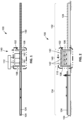
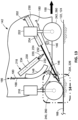
- Figure 2 is a side view of the manufacturing system 100.
- Figures 3 and 4 are respectively top and side views of the lamination station 140 showing the series of lamination heads 142.
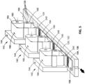
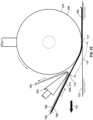
- Figure 5 is a perspective view of an example of a series of lamination heads 142 applying courses 194 of layup material 168 onto a substrate 122 or lamination surface 120 such as lamination mandrel 124, moving underneath the lamination heads 142.
- Each of the lamination heads 142 has bi-directional layup capability for dispensing layup material 168 onto the substrate 122.
- each lamination head 142 is configured to dispense layup material 168 during movement relative to the substrate 122 (e.g., lamination mandrel 124) along a first direction of travel 150 ( Figure 12 ), and also dispense layup material 168 during movement relative to the substrate 122 along a second direction of travel 152 ( Figure 18 ) opposite the first direction of travel 150.
- the bi-directional layup capability of the lamination heads 142 enables a relatively higher rate of manufacturing than is achievable with lamination heads that are limited to dispensing layup material 168 along a single direction of travel.
- the bi-directional capability of the lamination heads 142 reduces off-part movement of the lamination heads 142 that would otherwise be required if each lamination head were limited to dispensing layup material 168 while moving in a single direction of travel.
- lamination heads that are limited to dispensing layup material 168 in a single direction of travel require the lamination heads to lift off of the substrate 122 at the end of each course 194 of layup material 168, move back over the substrate 122 in a second direction of travel 152 opposite the first direction of travel 150, and start applying another course 194 of layup material 168 over or parallel to the previous course 194 of layup material 168 while moving along the first direction of travel 150.
- the elimination of off-part movement of the presently-disclosed bi-directional lamination heads 142 significantly reduces the amount of time required to lay up the composite laminate 196.
- the bi-directional layup capability of the presently-disclosed lamination heads 142 also provides advantages relative to lamination heads (not shown) configured to rotate 180 degrees at the end of a first course of layup material 168, and then reverse direction to lay up a second course of layup material 168 alongside or over the first course.
- a rotating lamination head may be more complex and heavier than a non-rotating lamination head.
- rotation of the individual lamination heads may be prohibitive due to proximity of adjacent lamination heads, which may limit clearance of the lamination heads during rotation.
- avoiding the need for rotating the presently-disclosed lamination heads 142 may significantly reduce cost and complexity.
- the layup material 168 ( Figure 13 ) dispensed by each lamination head 142 is initially supported by a backing layer 180 ( Figure 13 ) and is wound on a material roll 164 ( Figure 12 ).
- the backing layer 180 may be formed of a material that prevents adjacent wraps of layup material 168 from sticking to each other on the material roll 164.
- the backing layer 180 may provide a means for carrying tension when pulling (e.g., via the backing layer collection drum 190) the layup material 168 through the lamination head 142 without applying tension to the layup material 168.
- the backing layer 180 may be a paper material that is silicone-coated on one side, or the backing layer 180 may be a thin plastic film such as polyethylene film, or another material for releasably supporting the layup material 168.
- Each lamination head 142 includes a backing layer separation assembly 200 ( Figure 6 ) as described below for separating the layup material 168 from the backing layer 180 just prior to the layup material 168 being applied onto the substrate 122.
- each lamination head 142 is configured such that the separation of the layup material 168 from the backing layer 180 occurs at a relatively short distance (e.g., see Figures 16 and 22 ) from a compaction device 240, 242, and in a manner which reduces or eliminates tension in an unsupported section of the layup material 174 (e.g., Figures 16 and 22 ) just prior to compaction of the layup material 168 onto the substrate 122 by a compaction device 240, 242.
- the reduction or elimination of tension in the layup material 168 prior to compaction onto the substrate 122 advantageously reduces stretching of the layup material 168, relative to an increased amount of stretching that may occur in layup material 168 dispensed from a conventional lamination head.
- stretched layup material When stretched layup material (not shown) is applied to the substrate 122 (e.g., previously-applied layup material), the stretched layup material will attempt to contract back its nominal or unstretched length.
- the previously-applied layup material such as 0-degree composite tape (not shown) having axially-oriented reinforcing fibers, resists the contraction of the stretched layup material, and which results in bunching or local lifting of the composite plies or courses of the composite laminate. The bunching and/or local lifting may accumulate with subsequently applied layup material, unless the composite laminate is reworked.
- the presently-disclosed lamination head 142 improves the quality of the final composite laminate (not shown).
- the lamination heads 142 are stationary, and are configured to sequentially apply layup material 168 onto a movable lamination mandrel 124 and onto previously applied layup material 168 ( Figure 5 ) during one or more passes of the lamination mandrel 124 through the lamination station 140.
- the lamination heads 142 collectively dispense multiple courses 194 ( Figure 5 ) of layup material 168 as the lamination mandrel 124 passes underneath the lamination heads 142 along the first direction of travel 150 ( Figure 12 ), and along the second direction of travel 152 ( Figure 18 ).
- Each one of the lamination heads 142 in the series may be assigned a layup material 168 having a material configuration that corresponds to a desired ply stacking sequence of the final composite laminate.
- the outer surface of the lamination mandrel 124 may include a plurality of apertures 126 ( Figure 5 ) that may be coupled (e.g., via internal fluid conduits - not shown) to a vacuum pressure source 128 ( Figure 4 ). Activation of the vacuum pressure source 128 may generate vacuum pressure via the apertures 126 at the outer surface of the lamination mandrel 124 as a means to secure the layup material 168 in position on the lamination mandrel 124 during dispensing of the layup material 168 by the lamination heads 142.
- a release film (not shown) may be applied (e.g., via the lamination head 142) onto the lamination surface (e.g., lamination mandrel 124).
- the release film may be perforated to allow the vacuum pressure at the apertures 126 to vacuum couple to the composite laminate 196 being laid up on top of the release film.
- the manufacturing system 100 may include a base member 104 supported on a surface such as a factory floor.
- the lamination surface 120 may be configured as a lamination mandrel 124.
- the lamination mandrel 124 may be movable or slidable along longitudinal rails 130 extending along the length of the base member 104.
- the manufacturing system 100 may include a mandrel translation mechanism (not shown) such as a screw drive coupled to a drive motor for autonomously moving the lamination mandrel 124 under control of the controller 112.
- the mandrel translation mechanism may move the lamination mandrel 124 between a lamination surface home position 132 on one side of the lamination station 140, and a lamination surface aft position 134 on an opposite side of the lamination station 140.
- the lamination heads 142 may be supported by a lamination head support structure 102.
- the lamination head support structure 102 may include a longitudinal beam 110 to which the lamination heads 142 may be mounted. Opposing ends of the longitudinal beam 110 may be respectively coupled to a pair of crossbeams 108. The opposing ends of each crossbeam 108 may be supported by vertically-oriented posts 106 which may extend upwardly from a factory floor.
- the lamination head support structure 102 may be provided in any one of a variety of alternative configurations, and is not limited to the configuration shown in Figures 1-4 .
- the lamination surface 120 may be configured as a continuous loop lamination belt (not shown) supported by a series of internal belt rollers (not shown), and rotatably driven by a drive motor (not shown).
- the lamination belt may include an outer surface onto which layup material 168 may be dispensed by the lamination heads 142.
- the lamination surface 120 may be stationary, and the lamination heads 142 may be movable over the lamination surface 120 for dispensing layup material 168 for laying up a composite laminate 196.
- the lamination heads 142 may be supported by a gantry (not shown), a rail-mounted system (not shown), or a cantilevered support system (not shown) for moving the lamination heads 142 along the first direction of travel 150 and along the second direction of travel 152 while dispensing layup material 168 onto the lamination surface 120.
- the manufacturing system 100 may include one or more robotic devices (not shown) for moving the lamination heads 142 over a lamination surface 120.
- the manufacturing system 100 is not limited to a series of end-to-end lamination heads 142, but may include a single lamination head 142 that may be moved relative to a lamination surface 120 along the first direction of travel 150 and along the second direction of travel 152 for laying up a composite laminate 196.
- the lamination surface 120 is not limited to a generally planar elongated lamination surface 120, such as the presently-disclosed lamination mandrel 124.
- the lamination surface 120 may be a movable layup tool such as a rotatable layup mandrel (not shown).
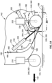
- the lamination head 142 includes a material supply drum 160, a cutter assembly 270, a backing layer separation assembly 200, first and second compaction devices 240, 242, and a backing layer collection drum 190, each of which may be supported by a mounting frame 144.
- the mounting frame 144 may be configured as a plate structure or a truss structure, and may coupled to the lamination head support structure 102 in a mechanically stable manner.
- the material supply drum 160 is configured to support a material roll 164 of backed material 166.
- the backing layer separation assembly 200 is configured to separate the layup material 168 from the backing layer 180, and guide the layup material 168 toward the substrate 122.
- the cutter assembly 270 is configured to cut the layup material 168 as the lamination head 142 approaches a designated start location and end location of a course 194 of layup material 168 being dispensed by the lamination head 142.
- the backing layer collection drum 190 is configured to take up or wind the backing layer 180 onto the backing layer collection drum 190 after separation of the layup material 168 from the backing layer 180 by the backing layer separation assembly 200.
- the lamination head 142 is shown prior to the threading of the backed material 166 ( Figure 12 ) through the above-mentioned components of the lamination head 142.
- the backed material 166 comprises a continuous length or strip of layup material 168 ( Figure 12 ) backed by a continuous backing layer 180 ( Figure 12 ).
- the layup material 168 may be a composite material, such as a continuous strip of fiber-reinforced polymer matrix material (e.g., prepreg tape).
- the matrix material may be a thermosetting resin or a thermoplastic resin.
- the reinforcing fibers may be glass fibers (e.g., fiberglass), carbon fibers, boron, aramid, metallic fibers, ceramic fibers, or other fiber materials.
- the composite layup material 168 may be a carbon-fiber epoxy-resin prepreg tape.
- the composite material may be unidirectional tape or multidirectional tape (e.g., woven or fabric tape).
- the layup material 168 may have a width of up to 12 inches or more
- the layup material 168 may be a continuous strip of non-composite material backed by a backing layer 180.
- the layup material 168 may be a metallic foil or a metallic mesh backed by a backing layer 180.
- the layup material 168 may be a processing material to assist in the processing (e.g., forming, consolidating, curing, handling) of the composite laminate 196.
- non-composite layup material examples include a release film, a tackifier film, a breather layer, a bleeder layer, peel ply, or any one of a variety of other types of non-composite layers, films, or adhesives that may be dispensed by the lamination head 142 prior to, during, or after the laying up of the composite laminate 196.
- the lamination head 142 may further include one or more guide rollers 146 mounted to the mounting frame 144.
- the lamination may include one or more guide surfaces 148 which may have a larger radius of curvature than the guide rollers 146. The larger radius of curvature of the guide surfaces 148 may facilitate the initial threading of the backed material 166 through the lamination head 142.
- the lamination head 142 includes two guide surfaces 148, each having an approximately quarter-circular shape. The guide rollers 146 and guide surfaces 148 may guide the backed material 166 ( Figure 12 ) through the cutter assembly 270 ( Figure 12 ) and the backing layer separation assembly 200 of the lamination head 142.
- the guide surfaces 148 respectively located above and below the cutter assembly 270 may facilitate the tensioning of the backed material 166 ( Figure 12 ) to enable precise control of the cutting of the layup material 168 ( Figure 12 ) without severing the backing layer 180.
- the guide rollers 146 and guide surfaces 148 may define a path for the backed material 166 through the lamination head 142 that prevents contact of the backed material 166 with the first and second compaction devices 240, 242, the first and second separation devices 202, 218, and other components of the lamination head 142 during dispensing of layup material 168 when the lamination head 142 is moving in the first direction of travel 150 ( Figure 12 ) and when the lamination head 142 is moving and the second direction of travel 152 ( Figure 18 ).
- the cutter assembly 270 may include a cutter module 272 and a cutter platen 274.
- the cutter platen 274 may be fixedly mounted to the mounting frame 144.
- the cutter module 272 may have at least one cutter blade 276 ( Figure 8 ).
- the cutter module 272 may be configured to horizontally translate away from the cutter platen 274 to a module home position (not shown) in which the cutter module 272 and the cutter platen 274 are spaced apart from each other.
- the cutter module 272 may horizontally translate back toward the cutter platen 274 to a module engagement position in which the backed material 166 is sandwiched between the cutter module 272 and the cutter platen 274, as shown in Figure 12 .
- the depth of the cutter blade 276 may be precisely controlled to cut only the layup material 168 without cutting the backing layer 180.
- the processor may control the cutter assembly 270 in a manner to cut the layup material 168 immediately prior to the start of each course 194 ( Figure 5 ) of layup material 168 to be dispensed by the lamination head 142, and also cut the layup material 168 immediately prior to the lamination head 142 arriving at the predetermined end of the course 194.
- the cut line 282 (e.g., Figures 9-11 ) in the layup material 168 creates a layup material leading edge 176 and a layup material trailing edge 178 abutting the layup material leading edge 176.
- the layup material leading edge 176 arrives at the horn distal end 206 of the first horn 204 ( Figure 15 ) or second horn 220 ( Figure 21 )
- the layup material leading edge 176 peels away from the backing layer 180 and is directed toward the substrate 122 and respectively underneath the first compaction device 240 ( Figure 15 ) or second compaction device 242 ( Figure 21 ), depending on whether the lamination head 142 is moving along the first direction of travel 150 ( Figure 13 ) or second direction of travel 152 ( Figure 19 ), as described in greater detail below.
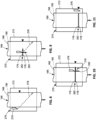
- FIG. 8 shown is the progression of a cut line 282 being formed in the layup material 168 as the backed material 166 moves at a material feed rate through the cutter assembly 270.
- Figure 8 shows the cutter blade 276 at a start location of the intended cut line 282 prior to the cutter blade 276 moving across the backed material 166 along a blade path angle.
- the cutter blade 276 may be configured to cut the layup material 168 as the backed material 166 moves along the cutter platen 274.
- Figures 9-10 shows the cutter blade 276 moving along the plate path angle at a blade speed defining a blade travel vector 278 for cutting the layup material 168 along the intended cut line 282.
- the blade travel vector 278 may have a longitudinal component 282 that is parallel to the lengthwise direction of the backed material 166.
- the longitudinal component 282 of the blade travel vector 278 is proportional to the material feed rate.
- Figure 11 shows the cut line 282 formed in the layup material 168.
- the depth of the cutter blade 276 may be precisely controlled such that the backing layer 180 remains at least partially intact after cutting the layup material 168.
- the intended cut line 282 is oriented perpendicular to the lengthwise direction of the backed material 166.
- the longitudinal component 282 of the blade travel vector 278 is equivalent to the material feed rate.
- the longitudinal component 282 of the blade travel vector 278 is either less than or greater than the material feed rate.
- moving the cutter blade 276 along the above-described blade travel vector 278 enables the layup material 168 to be cut without stopping the application of layup material 168 onto the substrate 122.
- the backing layer separation assembly 200 (e.g., Figure 12 ) is configured to receive the backed material 166 after being threaded through the cutter assembly 270, as mentioned above.
- the backing layer separation assembly 200 includes a first separation device 202 and a second separation device 218.
- the first separation device 202 includes a first horn 204 which is movable between a separation device retracted position 224 ( Figure 7 ) and a separation device extended position 226 ( Figures 12-13 ) associated with the first separation device 202.
- the second separation device 218 includes a second horn 220 which is also movable between a separation device retracted position 224 ( Figure 7 ) and a separation device extended position 226 ( Figures 18-19 ) associated with the second separation device 218.
- the first separation device 202 may include a first separation device actuator 216 configured as a linear actuator 228 to move the first horn 204 between the separation device retracted position 224 and the separation device extended position 226 ( Figures 12-13 ) associated with the first separation device 202.
- the second separation device 218 may include a second separation device actuator 222 which may also be configured as a linear actuator 228 to move the second separation device 218 between the separation device retracted position 224 and the separation device extended position 226 ( Figures 18-19 ) associated with the second separation device 218.
- each linear actuator 228 may be configured as a pneumatic actuator having a cylinder 230 and a rod 232 that is extensible from the cylinder 230.
- the linear actuator 228 may be a single-acting actuator or a double-acting actuator.
- the linear actuator 228 may be a hydraulic actuator or an electromechanical actuator.
- the first separation device 202 and the second separation device actuator 222 each provide a simple mechanism for respectively moving the first horn 204 and the second horn 220 into close proximity respectively to the first compaction device 240 and second compaction device 242.
- the ability to position the first horn 204 and second horn 220 in close proximity respectively to the first compaction device 240 and second compaction device 242 advantageously reduces the length of an unsupported section of layup material 174 between the horn distal end 206 and the substrate 122 (e.g., see Figures 16 and 22 ), and which reduces or minimizes undesirable tensioning and stretching of the layup material 168 prior to compaction onto the substrate 122.
- the unsupported section of layup material 174 is located between a layup material compaction point 172 respectively associated with the first or second compaction device 240, 242, and a layup material separation point 170 on the horn distal end 206 (i.e., respectively of the first or second horn 204, 220) where the layup material 168 separates from the backing layer 180.
- the lamination head 142 also includes the first compaction device 240 and the second compaction device 242, each of which is configured to apply compaction pressure onto the layup material 168 against the substrate 122 as the layup material 168 is dispensed by the lamination head 142.
- the first compaction device 240 is configured to apply compaction pressure onto the layup material 168 against the substrate 122 at a layup material compaction point 172 ( Figure 16 ) underneath the first compaction device 240 as the lamination head 142 moves along the first direction of travel 150 ( Figure 16 ).
- the second compaction device 242 is configured to apply compaction pressure onto the layup material 168 against the substrate 122 at a layup material compaction point 172 ( Figure 22 ) underneath the second compaction device 242 when the lamination head 142 is moving along the second direction of travel 152 ( Figure 22 ).
- the first and second compaction devices 240, 242 may be provided in alternative configurations.
- the first and second compaction devices 240, 242 may each be configured as a compaction shoe (not shown), or as a resiliently compressible compaction bladder (not shown) for glide-forming of the layup material 168 onto a contoured lamination mandrel (not shown) having an outer surface that has a non-planar cross-sectional shape.
- the first compaction device 240 may include a first compaction device actuator 248 configured as a linear actuator 228 to move the first compaction device 240 between a compaction device retracted position 260 (e.g., a raised position) and a compaction device extended position 262 (e.g., a lowered position - Figures 12-13 ) associated with the first compaction device 240.
- a compaction device actuator 248 configured as a linear actuator 228 to move the first compaction device 240 between a compaction device retracted position 260 (e.g., a raised position) and a compaction device extended position 262 (e.g., a lowered position - Figures 12-13 ) associated with the first compaction device 240.
- the second compaction device 242 may include a second compaction device actuator 250 also configured as a linear actuator 228 to move the second compaction device 242 between a compaction device retracted position 260 (e.g., a raised position) and a compaction device extended position 262 (e.g., a lowered position - Figures 18-19 ) associated with the second compaction device 242.
- a compaction device retracted position 260 e.g., a raised position
- a compaction device extended position 262 e.g., a lowered position - Figures 18-19
- the first or second compaction device 240, 242 When in the compaction device retracted position 260, the first or second compaction device 240, 242 may be in noncontacting relation to the substrate 122.
- the first or second compaction device 240, 242 may be in contact with the substrate 122.
- the substrate 122 may be described as the surface of the lamination mandrel 124 or the recently dispensed course 194
- the first compaction device 240 may include a first compaction device actuator 248.
- the second compaction device 242 may include a second compaction device actuator 250.
- the first compaction device actuator 248 and/or the second compaction device actuator 250 may be configured as a linear actuator 228 to respectively move the first compaction device 240 and the second compaction device 242 between the compaction device retracted position 260 and the compaction device extended position 262.
- the first compaction device 240 when the first compaction device 240 is in the compaction device extended position 262, the second compaction device 242 may be in the compaction device retracted position 260.
- the first compaction device 240 may be in the compaction device retracted position 260.
- the first compaction device actuator 248 and the second compaction device actuator 250 are each configured as a linear actuator 228.
- the linear actuator 228 may be a pneumatic actuator having a cylinder 230 and a rod 232 which may be extensible from the cylinder 230.
- the first and second compaction device actuators 248, 250 may be hydraulic actuators or electromechanical actuators.
- the first compaction device actuator 248 and the second compaction device actuator 250 may be oriented such that the rod 232 of the linear actuator 228 is vertically oriented, which may simplify the mounting and operation of the linear actuator 228.
- the first horn 204 when the first separation device 202 is in the separation device extended position 226, the first horn 204 is in close proximity to the layup material compaction point 172 ( Figure 16 ) associated with the first compaction device 240.
- the first horn 204 is configured to cause the layup material 168 to separate from the backing layer 180 and direct the layup material 168 toward the substrate 122 and underneath the first compaction device 240 as the lamination head 142 moves along the first direction of travel 150.
- the second separation device 218 when the second separation device 218 is in the separation device extended position 226, the second horn 220 is in close proximity to the layup material compaction point 172 ( Figure 22 ) associated with the second compaction device 242.
- the second horn 220 is configured to cause the layup material 168 to separate from the backing layer 180 and direct the layup material 168 toward the substrate 122 and underneath the second compaction device 242 as the lamination head 142 moves along the second direction of travel 152 opposite the first direction of travel 150.
- first horn 204 and the second horn 220 each have a horn distal end 206.
- the horn distal end 206 may have a relatively small radius of curvature 214 to cause the layup material leading edge 176 to separate from the backing layer 180 as the backing layer 180 moves around the horn distal end 206.
- the first horn 204 and second horn 220 are each configured such that the separation of the layup material leading edge 176 from the backing layer 180 (e.g., Figures 15 and 21 ) results in the layup material leading edge 176 moving toward the substrate 122 and respectively underneath the first and second compaction devices 240, 242 ( Figures 16 and 22 ).
- the radius of curvature 214 of the horn distal end 206 is such that the bending stiffness of the layup material 168 (i.e., in the axial direction) results in a peel force which urges the layup material 168 away from the backing layer 180 as the backing layer 180 moves around the horn distal end 206.
- the relatively small radius of curvature 214 is such that the peel force of the layup material 168 exceeds the strength of the adhesive bond between the layup material 168 and the backing layer 180, and results in the separation of the layup material 168 from the backing layer 180.
- a relatively small radius of curvature 214 allows the horn distal end 206 of the first horn 204 and second horn 220 to be positioned in close proximity to the compaction device outer surface 246 (e.g., of the compaction roller 244) respectively of the first and second compaction devices 240, 242.
- the length of the unsupported section of layup material 174 ( Figures 16 and 22 ) between the horn distal end 206 and the layup material compaction point 172 may be reduced, relative to the length of unsupported section of layup material 174 that would otherwise occur if the horn distal end 206 had a large radius of curvature 214.
- the first separation device actuator 216 and the second separation device actuator 222 may each include an actuator axis 234.
- the actuator axis 234 of the first separation device actuator 216 may be oriented in crossing relation to the actuator axis 234 of the second separation device actuator 222, which may allow for positioning the first and second separation devices 202, 218 in close proximity to each other.
- the first horn 204 when the first horn 204 is in the separation device retracted position 224, the first horn 204 is on a side of the actuator axis 234 of the second separation device actuator 222 at a location providing clearance for the second horn 220 to move between the separation device retracted position 224 and the separation device extended position 226 of the second horn 220.
- the second horn 220 When the second horn 220 is in the separation device retracted position 224, the second horn 220 is on a side of the actuator axis 234 of the first separation device actuator 216 at a location providing clearance for the first horn 204 to move between the separation device retracted position 224 and the separation device extended position 226 of the first horn 204.
- the first separation device 202 is configured to move the first horn 204 from the separation device retracted position 224 ( Figure 7 ) to the separation device extended position 226 ( Figures 12-13 ) to allow the lamination head 142 to dispense layup material 168 while moving along the first direction of travel 150.
- the second separation device 218 is configured to move the second horn 220 from the separation device retracted position 224 ( Figure 7 ) to the separation device extended position 226 ( Figures 18-19 ) to allow the lamination head 142 to dispense layup material 168 while moving along the second direction of travel 152.
- the actuator axis 234 of the first separation device actuator 216 and the second separation device actuator 222 may be oriented at an angle of less than 60 degrees relative to the substrate 122 surface.
- the angle of orientation of the actuator axes 234 of the first and second separation device actuators 216, 222 may be respectively measured relative to the first direction of travel 150 ( Figure 13 ) and the second direction of travel 152 ( Figure 19 ).
- each actuator axis 234 may be oriented at an angle of less than 30 degrees relative to the surface of the substrate 122.
- the actuator axis 234 of the first separation device actuator 216 may be oriented at an angle that points the horn distal end 206 of the first horn 204 in a downstream direction (e.g., relative to the first direction of travel 150 of the lamination head) and toward the layup material compaction point 172 of the first compaction device 240.
- the actuator axis 234 of the second separation device actuator 222 may be oriented at an angle that points the horn distal end 206 respectively of the second horn 220 in a downstream direction (e.g., relative to the second direction of travel 152 of the lamination head) and toward the layup material compaction point 172 respectively of the second compaction device 242.
- the first horn 204 and second horn 220 may each be positioned at a relatively small distance to the layup material compaction point 172 respectively associated with the first and second compaction devices 240, 242, and which results in a shorter length of unsupported section of layup material 174 ( Figures 16 and 22 ).
- the term "unsupported section of layup material” refers to the lengthwise section of layup material 168 that is unsupported by backing layer 180 and which is not in contact with the substrate 122.
- the combination of the relatively small radius of curvature 214 of the horn distal end 206, and the relatively small angle of the actuator axis 234 of the first and second separation device actuators 216, 222, allows the first and second horns 204, 220 to be positioned in close proximity to the layup material compaction point 172 respectively of the first and second compaction devices 240, 242, and which allows for a relatively short length of the unsupported section of layup material 174.
- the lamination head 142 dispensing layup material 168 during movement of the lamination head 142 relative to the lamination surface 120 along the first direction of travel 150.
- the first compaction device 240 e.g., compaction roller 244
- the substrate 122 e.g., the outer surface of the lamination mandrel 124
- the first horn 204 of the first separation device 202 is extended toward the first compaction device 240.
- the layup material 168 separates from the backing layer 180 and is compacted onto the substrate 122 by the first compaction device 240 while the lamination moves along the first direction of travel 150.
- the second compaction device 242 is in the compaction device retracted position 260 (e.g., raised position).
- the second horn 220 of the second separation device 218 is in the separation device retracted position 224 (e.g., raised position).
- the first notch region 256 may be bounded by the compaction device outer surface 246 of the first compaction device 240, a horizontal tangent 252 to the lowest point on the compaction device outer surface 246 (e.g., coincident with the substrate 122), and a vertical tangent 254 to the compaction device outer surface 246.
- the first horn 204 is oriented and configured in a manner to facilitate the separation of the layup material 168 from the backing layer 180, and for guiding the layup material 168 toward the substrate 122 and underneath the first compaction device 240.
- the first horn 204 may have a generally triangular cross-sectional shape with a rounded horn distal end 206. One side of the triangular cross-sectional shape of the first horn 204 may direct the layup material 168 toward the substrate 122 for compaction underneath the first compaction device 240.
- the horn distal end 206 may have a relatively small radius of curvature 214 that causes the layup material 168 to separate from the backing layer 180.
- the opposite side of the triangular cross-sectional shape of the first horn 204 may be oriented in general alignment with the backing layer collection drum 190, as shown in Figure 12 .
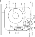
- FIG. 16 shown is an enlarged view of the first horn 204 in the separation device extended position 226 while layup material 168 is dispensed from the lamination head 142 moving relative to the lamination mandrel 124 along the first direction of travel 150.
- the horn distal end 206 is in close proximity to the compaction device outer surface 246.
- the relatively small radius of curvature 214 of the horn distal end 206 is such that the bending stiffness of the layup material 168 (i.e., in the axial direction) results in a peel force that exceeds the adhesive strength between the layup material 168 and the backing layer 180, resulting in separation of the layup material 168 from the backing layer 180 at the layup material separation point 170 on the horn distal end 206.
- the radius of curvature 214 of the horn distal end 206 of the first horn 204 and/or the second horn 220 may be in the range of approximately 0.25-1.0 inch.
- the horn distal end 206 may have a radius of curvature 214 that is less than 0.25 inch, or a radius of curvature 214 that is greater than 1.0 inch.
- the unsupported section of layup material 174 which extends between the layup material separation point 170 on the horn distal end 206, and the layup material compaction point 172 between the first compaction device 240 and the substrate 122.
- the ability to position the horn distal end 206 into close proximity to the substrate 122 and the compaction device outer surface 246 results in a relatively short length of the unsupported section of layup material 174, which reduces undesirable stretching of the unsupported section of layup material 174.
- reducing stretching of the layup material 168 reduces or eliminates local bunching and/or lifting of the layup material 174 that may accumulate in successively-applied courses 194 ( Figure 5 ) of the composite laminate 196, unless the composite laminate 196 is reworked.
- the horn distal end 206 includes a roller 210 configured to freely rotate about a roller axis 212 while the backing layer 180 moves over the horn distal end 206.
- the roller 210 in Figure 17 is an alternative to the horn distal end 206 shown in Figure 16 , which is configured as a sliding surface 208 or low-friction surface to facilitate free sliding of the backing layer 180 over the horn distal end 206.
- the sliding surface 208 may be a relatively smooth or polished surface, and may be formed of a metallic material or a non-metallic material.
- the sliding surface 208 of the horn distal end 206 may include a low-friction coating such as Teflon TM .
- the cutter assembly 270 forms a cut line 282 ( Figure 11 ) across the width of the layup material 168 while the backed material 166 is moving through the cutter assembly 270.
- the cut line 282 defines a layup material leading edge 176 and a layup material trailing edge 178.
- the rotation of the backing layer collection drum 190 may be temporarily halted to stop the movement of the backed material 166 through the lamination head 142, thereby preventing the layup material leading edge 176 ( Figure 11 ) from following the layup material trailing edge 178 ( Figure 11 ) toward the substrate 122.
- the lamination head 142 continues to move along the first direction of travel 150 until the layup material trailing edge 178 has been compacted onto the substrate 122 by the first compaction device 240.
- the layup material trailing edge 178 defines the end of the course 194 of layup material 168.
- the movement of the lamination head 142 may then stop, the first compaction device 240 retracts away from the substrate 122, and the first horn 204 retracts away from the first compaction device 240, as shown in Figure 18 .
- the second compaction device 242 is lowered into its compaction device extended position 262 onto the substrate 122, and the second horn 220 is extended to its separation device extended position 226 proximate the second compaction device 242.
- the lamination head 142 starts moving along the second direction of travel 152 opposite the first direction of travel 150, and the rotation of the backing layer collection drum 190 is restarted to thereby resume pulling the backed material 166 through the lamination head 142.
- layup material leading edge 176 When the previously-mentioned layup material leading edge 176 ( Figure 11 ) reaches the layup material separation point 170 ( Figure 22 ) on the second horn 220, the layup material leading edge 176 separates from the backing layer 180 and moves toward the substrate 122 ( Figure 21 ) underneath the second compaction device 242 to start another course 194 of layup material 168. The process continues until a predetermined number of courses 194 ( Figure 5 ) of layup material 168 are applied to the substrate 122, thereby resulting in the uncured composite laminate 196 ( Figure 5 ).
- the horn distal end 206 of the second horn 220 in the separation device extended position 226 may extend into a second notch region 258 associated with the second compaction device 242, similar to the above-described the first notch region 256 associated with the first horn 204 as shown in Figure 14 .
- the second notch region 258 for the second horn 220 may be bounded by the compaction device outer surface 246 of the second compaction device 242, the horizontal tangent 252 to the lowest point of the compaction device outer surface 246 (e.g., coincident with the substrate 122), and the vertical tangent 254 to the compaction device outer surface 246 of the second compaction device 242.
- Figure 21 shows the layup material leading edge 176 after separation from the backing layer 180 and moving toward the substrate 122 as the backing layer 180 moves around the horn distal end 206 of the second horn 220.
- the second horn 220 may be configured similar to the above-described first horn 204.
- the second horn 220 may have a triangular cross-sectional shape in which one side of the triangular cross-sectional shape directs the layup material 168 toward the substrate 122 for compaction underneath the second compaction device 242.
- the opposite side of the triangular cross-sectional shape of the second horn 220 may orient the backing layer 180 toward the guide roller 146 ( Figure 19 ) located immediately adjacent to the second compaction device 242.
- the guide roller 146 may redirect the backing layer 180 toward the backing layer collection drum 190 ( Figure 18 ).
- the horn distal end 206 of the second horn 220 may have a relatively small radius of curvature 214, and may be configured in any one the above-described configurations of the first horn 204.
- the small radius of curvature 214 of the horn distal end 206 of the second horn 220 may cause the layup material 168 to separate from the backing layer 180 at the layup material separation point 170 on the horn distal end 206, similar to the configuration of the first horn 204.
- the close proximity of the second horn 220 to the second compaction device 242 results in a relatively short length of unsupported section of layup material 174 between the layup material separation point 170, and the layup material compaction point 172 underneath the second compaction device 242, and which may prevent undesirable stretching of the unsupported section of layup material 174, thereby reducing or avoiding local bunching or lifting of the layup material 174 of the composite laminate 196 ( Figure 5 ).
- the movement of the lamination head 142 relative to the lamination surface 120 may be controlled by the controller 112 ( Figure 1 ) executing computer-readable program instructions (e.g., a numerical control program).
- the controller 112 may also control the operation of the cutter assembly 270 ( Figure 6 ), the rotation of the material supply drum 160 ( Figure 6 ), the rotation of the backing layer collection drum 190 ( Figure 6 ), the extension and retraction of the first and second horns 204, 220 ( Figure 6 ), and the extension and retraction of the first and second compaction devices 240, 242 ( Figure 6 ).
- the controller 112 may translate the lamination mandrel 124 ( Figure 1 ) in synchronization with the operation the collection drum drive motor 192 ( Figure 6 ) to rotate the backing layer collection drum 190 (e.g., optionally in coordination with the rotational speed of the supply drum drive motor 162) for pulling the backed material 166 through the lamination head 142 while maintaining a constant tension load in the backing layer 180 during dispensing of layup material 168 from the lamination head 142.
- controller 112 may control the movement of the lamination mandrel 124 and the rotational speed of the backing layer collection drum 190 and/or the material supply drum 160 in a manner such that any tension load in the unsupported section of layup material 174 (e.g., Figures 16 and 22 ) is lower than the tension load in the backing layer 180.
- the method 300 may include supporting on a mounting frame 144 the material supply drum 160, the backing layer collection drum 190, the backing layer separation assembly 200, the first compaction device 240, and the second compaction device 242.
- the mounting frame 144 may be supported by a lamination head support structure 102 configured to suspend the lamination head 142 above a movable lamination surface 120 such as a lamination mandrel 124.
- the mounting frame 144 may be supported on a movable system such as a gantry (not shown) or a robotic device (not shown) for moving the lamination head 142 over a stationary lamination surface (not shown) or a moving lamination surface 120.
- a movable system such as a gantry (not shown) or a robotic device (not shown) for moving the lamination head 142 over a stationary lamination surface (not shown) or a moving lamination surface 120.
- Step 302 of the method 300 includes feeding a backed material 166 from a material roll 164 to the backing layer separation assembly 200 of the lamination head 142.
- the material roll 164 is mounted on the material supply drum 160.
- the backed material 166 comprises the layup material 168 backed by a backing layer 180.
- the backing layer separation assembly 200 has a first separation device 202 and a second separation device 218 respectively having a first horn 204 and a second horn 220.
- Step 304 of the method 300 includes moving the first horn 204 into close proximity to a layup material compaction point 172 associated with a first compaction device 240.
- the method 300 may comprise retracting the second horn 220 away from the second compaction device 242 to a location providing clearance for the first horn 204 to move between the separation device retracted position 224 and the separation device extended position 226 of the first horn 204.
- Step 304 may include actuating a first separation device actuator 216 to move the first horn 204 between a separation device retracted position 224 and a separation device extended position 226 associated with the first horn 204.
- the first horn 204 may be mounted on the end of a rod 232 extending from a cylinder 230 of the first separation device actuator 216. Movement of the first horn 204 may be performed by extending the rod 232 from the cylinder 230, wherein the rod 232 defines an actuator axis 234 of the first separation device actuator 216.
- step 304 may comprise moving the first horn 204 along the actuator axis 234, which may be oriented at an angle of less than 60 degrees relative to the first direction of travel 150.
- the relatively shallow angle of orientation of the actuator axis 234 may allow the first horn 204 to be positioned in relatively close proximity to the substrate 122 and the compaction device outer surface 246 of the first compaction device 240.
- Step 304 of moving the first horn 204 into close proximity to the layup material compaction point 172 associated with the first compaction device 240 may comprise moving the horn distal end 206 of the first horn 204 to within 0.5 inch of the substrate 122 and/or the compaction device outer surface 246 of the first compaction device 240.
- the method 300 may include moving the horn distal end 206 of the first horn 204 into a first notch region 256 defined by the substrate 122 and the compaction device outer surface 246.
- the first notch region 256 may be bounded by the substrate 122, the compaction device outer surface 246 of the first compaction device 240, and a vertical tangent 254 to the compaction device outer surface 246.
- Step 306 of the method 300 includes separating, using the first horn 204, the layup material 168 from the backing layer 180, and directing the layup material 168 toward the layup material compaction point 172 associated with the first compaction device 240 while moving the lamination head 142 along a first direction of travel 150.
- Step 306 of separating, using the first horn 204, the layup material 168 from the backing layer 180 may comprise pulling the backing layer 180 over a generally triangular cross-sectional shape of the first horn 204.
- the triangular cross-sectional shape of the first horn 204 may direct the layup material 168 generally toward the layup material compaction point 172 underneath the first compaction device 240, and may also orient the backing layer 180 into general alignment with the backing layer collection drum 190.
- Step 306 of separating, using the first horn 204, the layup material 168 from the backing layer 180 comprises pulling the backing layer 180 around a relatively small radius of curvature 214 of the horn distal end 206 of the first horn 204, thereby causing the layup material leading edge 176 to separate from the backing layer 180 as the backing layer 180 moves around the horn distal end 206.
- the relatively small radius of curvature 214 of the horn distal end 206 is such that the bending stiffness of the layup material 168 results in a peel force that exceeds the strength of the adhesive bond between the layup material 168 and the backing layer 180, and results in the separation of the layup material 168 from the backing layer 180.
- Step 306 may optionally include pulling the backing layer 180 around a sliding surface 208 of the horn distal end 206.
- the sliding surface 208 may have a static (i.e., non-movable) outer surface, which may be a low-friction surface or a coated surface.
- step 306 may include pulling the backing layer 180 around a roller 210 configured to freely rotate about a roller axis 212 as the backing layer 180 moves over the roller 210.
- the method 300 may comprise moving the first compaction device 240 into the compaction device extended position 262 in which the first compaction device 240 is in contact with the substrate 122.
- the first compaction device 240 may be moved into contact with the substrate 122 prior to, during, or immediately after moving the first horn 204 into close proximity to the first compaction device 240.
- the first compaction device 240 may be moved into the compaction device extended position 262 by extending a rod 232 from a cylinder 230 of a first separation device actuator 216 mounted to the lamination head 142.
- the method 300 may include compacting, using the first compaction device 240, the layup material 168 onto the substrate 122 as the layup material 168 is dispensed from the lamination head 142 while moving along the first direction of travel 150.
- the first compaction device 240 may be configured as a compaction roller 244, a compaction shoe, a compaction bladder, or another compaction device configuration.
- the method 300 includes step 308 of retracting the first horn 204 away from the first compaction device 240. As mentioned above, relative movement of the lamination head 142 along the first direction of travel 150 may be halted once the layup material trailing edge 178 is compacted onto the substrate 122 by the first compaction device 240.
- Step 310 of the method 300 includes moving the second horn 220 into close proximity to a layup material compaction point 172 associated with a second compaction device 242.
- the second horn 220 may be extended into close proximity with the second compaction device 242 at approximately the same time or immediately after the first horn 204 is retracted away from the first compaction device 240.
- Step 310 of moving the second horn 220 may include actuating a second separation device actuator 222 to move the second horn 220 between the separation device retracted position 224 and the separation device extended position 226 associated with the second horn 220.
- step 310 may include extending a rod 232 from a cylinder 230 of a second separation device actuator 222, wherein the second horn 220 may be mounted on the end of the rod.
- the actuator axis 234 of the second separation device actuator 222 may be oriented at an angle of less than 60 degrees relative to the second direction of travel 152.
- step 310 may include retracting the first horn 204 away from the second compaction device 242 to a location providing clearance for the second horn 220 to move between the separation device retracted position 224 and the separation device extended position 226 of the second horn 220.
- Step 310 of moving the second horn 220 into close proximity to the layup material compaction point 172 associated with the second compaction device 242 may comprise moving the horn distal end 206 of the second horn 220 into a second notch region 258 associated with the second compaction device 242. Similar to the above-described first notch region 256 of the first compaction device 240, the second notch region 258 of the second compaction device 242 may be bounded by the substrate 122, the compaction device outer surface 246 of the second compaction device 242, and a vertical tangent 254 to the compaction device outer surface 246 of the second compaction device 242. In some examples, step 310 may include moving the second horn 220 to within 0.5 inch of the substrate 122 and/or the compaction device outer surface 246 of the second compaction device 242.
- Step 312 of the method 300 includes separating, using the second horn 220, the layup material 168 from the backing layer 180, and directing the layup material 168 toward the layup material compaction point 172 associated with the second compaction device 242 while moving the lamination head 142 along a second direction of travel 152 opposite the first direction of travel 150.
- Step 312 of separating, using the second horn 220, the layup material 168 from the backing layer 180 may comprise pulling the backing layer 180 over a generally triangular cross-sectional shape of the second horn 220.
- the triangular cross-sectional shape of the second horn 220 may direct the layup material 168 generally toward the layup material compaction point 172 underneath the second compaction device 242, and may also orient the backing layer 180 toward a guide roller 146 which may be redirect the backing layer 180 toward the backing layer collection drum 190.
- Step 312 may include pulling the backing layer 180 around a relatively small radius of curvature 214 of the horn distal end 206 of the second horn 220 to cause the layup material leading edge 176 to separate from the backing layer 180, similar to above-described separation of the layup material 168 from the backing layer 180 moving around the first horn 204.
- the backing layer 180 may be pulled around a sliding surface 208 of the horn distal end 206 of the second horn 220, or the backing layer 180 may be pulled around a freely-rotatable roller 210 mounted on the horn distal end 206 of the second horn 220.
- the method 300 may comprise moving the second compaction device 242 into contact with the substrate 122 prior to the layup material 168 contacting the substrate 122.
- the second compaction device 242 may be configured as a compaction roller 244, a compaction shoe, a compaction bladder, or other compaction device configuration.
- the second compaction device 242 may be moved into contact with the substrate 122 prior to, during, or immediately after moving the second horn 220 into close proximity to the second compaction device 242. Similar to the above-described operation of the first compaction device 240, the second compaction device 242 may be moved into the compaction device extended position 262 by extending a rod 232 from a cylinder 230 of the second separation device actuator 222.
- the method 300 may include compacting, using the second compaction device 242, the layup material 168 onto the substrate 122 as the layup material 168 is dispensed from the lamination head 142 while moving along the second direction of travel 152.
- the method 300 may include defining a path for the backed material 166 through the lamination head 142 using one or more guide rollers 146 and/or guide surfaces 148.
- the guide rollers 146 and/or guide surfaces 148 may help to maintain tension in the backing layer 180.
- the method 300 may include pulling, using the backing layer collection drum 190, the backed material 166 through the lamination head 142 while maintaining constant tension load in the backing layer 180 during application of the layup material 168 onto the substrate 122.
- the lamination head 142 may include a collection drum drive motor 192 for rotating the backing layer collection drum 190.
- the method 300 may include controlling the rotational speed of the collection drum drive motor 192 in coordination with the speed of movement of the lamination surface 120 (e.g., lamination mandrel 124) in a manner causing the layup material 168 to be dispensed onto the substrate 122 with a tension load in the unsupported section of layup material 174 ( Figures 16 and 22 ) that is lower than the tension load in the backing layer 180.
- reducing or eliminating tension in the unsupported section of the layup material 174 may avoid undesirable stretching of the layup material 168, which may thereby improve the quality of the final composite laminate (not shown).
Description
- The present disclosure relates generally to manufacturing systems and, more particularly, to a lamination head for laying up composite laminates, and which has bi-directional layup capability.
- Composite materials are used in a wide variety of applications due to their favorable properties such as high specific strength, high specific stiffness, and high corrosion resistance. The manufacturing of a composite structure typically involves laying up multiple plies of layup material in a stacked formation on a lamination surface to form a composite laminate. The layup material is typically a fibrous material that is pre-impregnated with uncured resin (e.g., prepreg). For example, the layup material may be epoxy-impregnated carbon fiber prepreg.
- Automated layup machines enable the layup of composite laminates at relatively high production rates due to the relatively high layup material deposition rates of automated layup machines. A tape lamination head is one type of automated layup machine in which a continuous strip of layup material such as prepreg tape is dispensed from the lamination head onto a lamination surface as the lamination head is moved relative to the lamination surface. For example, a lamination head may dispense layup material while moving over a stationary lamination surface. Alternatively the lamination head may be stationary, and the lamination surface may move underneath the lamination head while the lamination head dispenses layup material. A lamination head may form each composite ply by successively laying up rows or courses of tape in side-by-side parallel relation to each other.
- A conventional lamination head may lay up each new course of tape while moving in a first direction of travel relative to the lamination surface. At the end of a course, the lamination head lifts off of the lamination surface and moves back over the lamination surface in a second direction of travel opposite the first direction of travel, and starts applying another course of tape along the first direction. The off-part movement of the lamination head each time it moves along the second direction undesirably adds to production flow time.
- In attempts to reduce off-part movement, certain types of lamination heads may be configured to rotate 180 degrees at the end of laying up a first course of layup material, and then reverse direction to lay up a second course of layup material alongside or over the first course. The capability for rotating the lamination head adds complexity to the manufacturing system due to the need to rotate the entire weight of the lamination head, the material supply, support cabling, and other associated components. Further adding to the complexity is the need to temporarily lift the lamination head off of the lamination surface prior to rotation, and then lower the lamination head back down onto the lamination surface once rotation is complete.
- In another attempt to reduce off-part movement, some conventional manufacturing systems include a first lamination head configured to dispense layup material while moving along a first direction of travel, and a second lamination head configured to dispense layup material while moving along a second direction of travel. However, such a manufacturing system doubles the quantity of lamination heads, and therefore increases the cost, complexity, and overall size of the manufacturing system.
EP3647029-A1 , in accordance with its abstract, states a lamination head has a material supply drum, a backing layer collection drum, and a backing layer separation assembly. The material supply drum supports a material roll of backed material comprising layup material backed by a backing layer. The backing layer collection drum moves from a collection drum home position to a collection drum engagement position proximate the material supply drum, engage a backing layer leading edge on the material roll, and moves back to the collection drum home position while dispensing a threadable portion of at least the backing layer. The backing layer separation assembly has a backing layer separation device and a backing layer separation mechanism. The backing layer separation device translates from a separation device home position to a separation device engagement position and pulls the threadable portion into proximity to the backing layer separation mechanism for separating the backing layer from the layup material. - As can be seen, there exists a need in the art for a lamination head that reduces off-part movement of the lamination head, and which avoids the costs and complexities associated with conventional manufacturing systems.
- A lamination head having a bi-directional layup capability for laying up a composite laminate according to
claim 1 and a method of bi-directionally applying a layup onto a substrate according to claim 9 are provided. The above-noted needs associated with manufacturing composite laminates are specifically addressed and alleviated by the present disclosure which provides a lamination head having bi-directional layup capability for laying up a composite laminate. The lamination head includes a material supply drum configured to support a material roll of backed material. The backed material comprises layup material backed by a backing layer. The lamination head also includes a first separation device and a second separation device respectively having a first horn and a second horn each movable between a separation device retracted position and a separation device extended position respectively associated with the first separation device and second separation device. The lamination head additionally includes a first compaction device and a second compaction device configured to alternatingly apply compaction pressure onto the layup material against a substrate at a layup material compaction point. When the first separation device is in the separation device extended position, the first horn is in close proximity to the layup material compaction point associated with the first compaction device, and the first horn is configured to cause the layup material to separate from the backing layer and direct the layup material toward the substrate and underneath the first compaction device as the lamination head moves along a first direction of travel. When the second separation device is in the separation device extended position, the second horn is in close proximity to the layup material compaction point associated with the second compaction device, and the second horn is configured to cause the layup material to separate from the backing layer and direct the layup material toward the substrate and underneath the second compaction device as the lamination head moves along a second direction of travel opposite the first direction of travel. - Also disclosed is a lamination head having bi-directional layup capability, including a material supply drum, first and second separation devices, and first and second compaction devices, as described above. When the first separation device is in the separation device extended position and the second separation device is in the separation device retracted position, the first horn is in close proximity to the layup material compaction point associated with the first compaction device for separating the layup material from the backing layer as the lamination head moves along a first direction of travel. When the second separation device is in the separation device extended position and the first separation device is in the separation device retracted position, the second horn is in close proximity to the layup material compaction point associated with the second compaction device for separating the layup material from the backing layer as the lamination head moves along a second direction of travel opposite the first direction of travel.
- In addition, disclosed is a method of bi-directionally applying layup material onto a substrate. The method includes feeding a backed material from a material roll to a backing layer separation assembly of a lamination head. The material roll is mounted on a material supply drum. The backed material comprises layup material backed by a backing layer. The backing layer separation assembly has a first separation device and a second separation device respectively having a first horn and a second horn. The method includes moving the first horn into close proximity to a layup material compaction point associated with a first compaction device. In addition, the method includes separating, using the first horn, the layup material from the backing layer and directing the layup material toward the layup material compaction point associated with the first compaction device while moving the lamination head along a first direction of travel. Furthermore, the method includes retracting the first horn away from the first compaction device, and moving the second horn into close proximity to a layup material compaction point associated with a second compaction device. The method also includes separating, using the second horn, the layup material from the backing layer and directing the layup material toward the layup material compaction point associated with the second compaction device while moving the lamination head along a second direction of travel opposite the first direction of travel.
- The features, functions and advantages that have been discussed can be achieved independently in various examples of the present disclosure or may be combined in yet other examples, further details of which can be seen with reference to the following description and drawings below.
- These and other features of the present disclosure will become more apparent upon reference to the drawings wherein like numbers refer to like parts throughout and wherein:
-
Figure 1 is top view of an example of a manufacturing system for laying up a composite laminate, and which includes a series of lamination heads, each having bi-directional layup capability for dispensing layup material onto a substrate during relative movement of the lamination head along a first direction of travel, and along a second direction of travel opposite the first direction of travel; -
Figure 2 is a side view of the manufacturing system ofFigure 1 ; -
Figure 3 is a magnified view of the portion of the manufacturing system identified byreference numeral 3 ofFigure 1 , and illustrating the series of lamination heads supported by a lamination head support structure; -
Figure 4 is a magnified view of the portion of the manufacturing system identified by reference numeral 4 ofFigure 2 , and illustrating the lamination heads supported above a lamination mandrel that is movable relative to the lamination heads, which are stationary; -
Figure 5 is a perspective view of an example of a series of lamination heads applying layup material onto a substrate (e.g., a lamination mandrel) moving underneath the lamination heads; -
Figure 6 is a magnified view of the lamination head identified byreference numeral 6 ofFigure 4 , and illustrating a material supply drum supporting a material roll of layup material backed by a backing layer, and further illustrating a backing layer separation assembly for separating the layup material from the backing layer, and additionally illustrating first and second compaction devices for compacting the layup material onto the substrate during relative movement of the lamination head while a backing layer collection drum collects the backing layer; -
Figure 7 is a magnified view of the portion of the lamination head identified by reference numeral 7 ofFigure 6 , and illustrating the first and second separation devices each in a separation device retracted position, and illustrating the first and second compaction devices each in a compaction device retracted position; -
Figure 8 is a view of the cutter assembly taken along line 8-8 ofFigure 6 , and illustrating an example of a cutter blade configured to cut the layup material along a blade angle path that is complementary to the material feed rate of the backed material; -
Figure 9 is a view of the cutter assembly showing further progression of the cutter blade moving along the blade path angle to cut the layup material along an intended cut line; -
Figure 10 is a view of the cutter assembly showing still further progression of the cutter blade during cutting of the layup material along the intended cut line which, in the example shown, is oriented perpendicular to the lengthwise direction of the backed material; -
Figure 11 is a view of the cutter assembly after cutting the layup material along the intended cut line; -
Figure 12 shows the lamination head dispensing layup material onto the substrate during movement relative to the substrate along the first direction of travel; -
Figure 13 is a magnified view of the portion of the lamination head identified byreference numeral 13 ofFigure 12 , and illustrating the first separation device in a separation device extended position for separating the layup material from the backing layer and directing the layup material toward the substrate and underneath the first compaction device; -
Figure 14 is a magnified view of the portion of the lamination head identified byreference numeral 14 ofFigure 13 , and illustrating a horn distal end of the first horn located within a first notch region defined between the compaction device outer surface of the first compaction device, a horizontal tangent to the compaction device outer surface, and a vertical tangent to the compaction device outer surface; -
Figure 15 shows the horn distal end separating the layup material from the backing layer, and directing the layup material toward the substrate and underneath the first compaction device during relative movement of the lamination head along the first direction of travel; -
Figure 16 shows the horn distal end in close proximity to the compaction device outer surface, and resulting in a relatively short length of the unsupported section of layup material extending between a layup material separation point on the horn distal end, and a layup material compaction point underneath the first compaction device; -
Figure 17 shows an example of the horn distal end having a roller which is freely rotatable as the backing layer moves over the horn distal end; -
Figure 18 shows the lamination head dispensing layup material onto the substrate during movement relative to the substrate along the second direction of travel; -
Figure 19 is a magnified view of the portion of the lamination head identified byreference numeral 19 ofFigure 18 , and illustrating the second separation device in the separation device extended position for separating the layup material from the backing layer and directing the layup material toward the substrate and underneath the second compaction device; -
Figure 20 is a magnified view of the portion of the lamination head identified byreference numeral 20 ofFigure 19 , and illustrating the horn distal end of the second horn located within a second notch region defined between the compaction device outer surface of the second compaction device, the horizontal tangent to the compaction device outer surface, and the vertical tangent to the compaction device outer surface; -
Figure 21 shows the horn distal end of the second compaction device separating the layup material from the backing layer, and directing the layup material toward the substrate and underneath the second compaction device during relative movement of the lamination head along the second direction of travel; -
Figure 22 shows the horn distal end in close proximity to the compaction device outer surface of the second compaction device, and resulting in a relatively short length of the unsupported section of layup material extending between the horn distal end and the layup material compaction point underneath the second compaction device; -
Figure 23 is a flowchart of a method of bi-directionally applying layup material onto a substrate. - Referring now to the drawings which illustrate preferred and various examples of the disclosure, shown in
Figure 1 is top view of an example of amanufacturing system 100 having alamination station 140 containing an end-to-end series of lamination heads 142 (e.g., fiber placement heads) for laying up an uncured composite laminate 196 (Figure 5 ).Figure 2 is a side view of themanufacturing system 100.Figures 3 and 4 are respectively top and side views of thelamination station 140 showing the series of lamination heads 142.Figure 5 is a perspective view of an example of a series of lamination heads 142 applyingcourses 194 oflayup material 168 onto asubstrate 122 or lamination surface 120 such aslamination mandrel 124, moving underneath the lamination heads 142. Each of the lamination heads 142 has bi-directional layup capability for dispensinglayup material 168 onto thesubstrate 122. In this regard, eachlamination head 142 is configured to dispenselayup material 168 during movement relative to the substrate 122 (e.g., lamination mandrel 124) along a first direction of travel 150 (Figure 12 ), and also dispenselayup material 168 during movement relative to thesubstrate 122 along a second direction of travel 152 (Figure 18 ) opposite the first direction oftravel 150. - The bi-directional layup capability of the lamination heads 142 enables a relatively higher rate of manufacturing than is achievable with lamination heads that are limited to dispensing
layup material 168 along a single direction of travel. In this regard, the bi-directional capability of the lamination heads 142 reduces off-part movement of the lamination heads 142 that would otherwise be required if each lamination head were limited to dispensinglayup material 168 while moving in a single direction of travel. For example, lamination heads (not shown) that are limited to dispensinglayup material 168 in a single direction of travel require the lamination heads to lift off of thesubstrate 122 at the end of eachcourse 194 oflayup material 168, move back over thesubstrate 122 in a second direction oftravel 152 opposite the first direction oftravel 150, and start applying anothercourse 194 oflayup material 168 over or parallel to theprevious course 194 oflayup material 168 while moving along the first direction oftravel 150. As may be appreciated, the elimination of off-part movement of the presently-disclosed bi-directional lamination heads 142 significantly reduces the amount of time required to lay up the composite laminate 196. - As mentioned above, the bi-directional layup capability of the presently-disclosed lamination heads 142 also provides advantages relative to lamination heads (not shown) configured to rotate 180 degrees at the end of a first course of
layup material 168, and then reverse direction to lay up a second course oflayup material 168 alongside or over the first course. As indicated above, a rotating lamination head may be more complex and heavier than a non-rotating lamination head. In the case of multiple lamination heads (not shown) arranged in series, rotation of the individual lamination heads may be prohibitive due to proximity of adjacent lamination heads, which may limit clearance of the lamination heads during rotation. Advantageously, avoiding the need for rotating the presently-disclosed lamination heads 142 may significantly reduce cost and complexity. - As described in greater detail below, the layup material 168 (
Figure 13 ) dispensed by eachlamination head 142 is initially supported by a backing layer 180 (Figure 13 ) and is wound on a material roll 164 (Figure 12 ). Thebacking layer 180 may be formed of a material that prevents adjacent wraps oflayup material 168 from sticking to each other on thematerial roll 164. In addition, thebacking layer 180 may provide a means for carrying tension when pulling (e.g., via the backing layer collection drum 190) thelayup material 168 through thelamination head 142 without applying tension to thelayup material 168. Thebacking layer 180 may be a paper material that is silicone-coated on one side, or thebacking layer 180 may be a thin plastic film such as polyethylene film, or another material for releasably supporting thelayup material 168. Eachlamination head 142 includes a backing layer separation assembly 200 (Figure 6 ) as described below for separating thelayup material 168 from thebacking layer 180 just prior to thelayup material 168 being applied onto thesubstrate 122. - Advantageously, each
lamination head 142 is configured such that the separation of thelayup material 168 from thebacking layer 180 occurs at a relatively short distance (e.g., seeFigures 16 and22 ) from acompaction device Figures 16 and22 ) just prior to compaction of thelayup material 168 onto thesubstrate 122 by acompaction device layup material 168 prior to compaction onto thesubstrate 122 advantageously reduces stretching of thelayup material 168, relative to an increased amount of stretching that may occur inlayup material 168 dispensed from a conventional lamination head. When stretched layup material (not shown) is applied to the substrate 122 (e.g., previously-applied layup material), the stretched layup material will attempt to contract back its nominal or unstretched length. However, the previously-applied layup material, such as 0-degree composite tape (not shown) having axially-oriented reinforcing fibers, resists the contraction of the stretched layup material, and which results in bunching or local lifting of the composite plies or courses of the composite laminate. The bunching and/or local lifting may accumulate with subsequently applied layup material, unless the composite laminate is reworked. Advantageously, in the presently-disclosedlamination head 142, reduced stretching of thelayup material 168 prior to compaction onto thesubstrate 122 reduces or eliminates local bunching that may otherwise occur in the composite laminate 196 (Figure 5 ). In this regard, the presently-disclosedlamination head 142 improves the quality of the final composite laminate (not shown). - As mentioned above, in the
example manufacturing system 100 ofFigures 1-5 , the lamination heads 142 are stationary, and are configured to sequentially applylayup material 168 onto amovable lamination mandrel 124 and onto previously applied layup material 168 (Figure 5 ) during one or more passes of thelamination mandrel 124 through thelamination station 140. The lamination heads 142 collectively dispense multiple courses 194 (Figure 5 ) oflayup material 168 as thelamination mandrel 124 passes underneath the lamination heads 142 along the first direction of travel 150 (Figure 12 ), and along the second direction of travel 152 (Figure 18 ). Each one of the lamination heads 142 in the series may be assigned alayup material 168 having a material configuration that corresponds to a desired ply stacking sequence of the final composite laminate. The outer surface of thelamination mandrel 124 may include a plurality of apertures 126 (Figure 5 ) that may be coupled (e.g., via internal fluid conduits - not shown) to a vacuum pressure source 128 (Figure 4 ). Activation of thevacuum pressure source 128 may generate vacuum pressure via theapertures 126 at the outer surface of thelamination mandrel 124 as a means to secure thelayup material 168 in position on thelamination mandrel 124 during dispensing of thelayup material 168 by the lamination heads 142. In some examples, a release film (not shown) may be applied (e.g., via the lamination head 142) onto the lamination surface (e.g., lamination mandrel 124). The release film may be perforated to allow the vacuum pressure at theapertures 126 to vacuum couple to the composite laminate 196 being laid up on top of the release film. - Referring to
Figures 1-4 , themanufacturing system 100 may include abase member 104 supported on a surface such as a factory floor. As mentioned above, the lamination surface 120 may be configured as alamination mandrel 124. Thelamination mandrel 124 may be movable or slidable alonglongitudinal rails 130 extending along the length of thebase member 104. For example, themanufacturing system 100 may include a mandrel translation mechanism (not shown) such as a screw drive coupled to a drive motor for autonomously moving thelamination mandrel 124 under control of thecontroller 112. The mandrel translation mechanism may move thelamination mandrel 124 between a laminationsurface home position 132 on one side of thelamination station 140, and a lamination surface aftposition 134 on an opposite side of thelamination station 140. - In the example shown, the lamination heads 142 may be supported by a lamination
head support structure 102. The laminationhead support structure 102 may include alongitudinal beam 110 to which the lamination heads 142 may be mounted. Opposing ends of thelongitudinal beam 110 may be respectively coupled to a pair ofcrossbeams 108. The opposing ends of eachcrossbeam 108 may be supported by vertically-orientedposts 106 which may extend upwardly from a factory floor. However, the laminationhead support structure 102 may be provided in any one of a variety of alternative configurations, and is not limited to the configuration shown inFigures 1-4 . - As an alternative to a
movable lamination mandrel 124, the lamination surface 120 may be configured as a continuous loop lamination belt (not shown) supported by a series of internal belt rollers (not shown), and rotatably driven by a drive motor (not shown). The lamination belt may include an outer surface onto whichlayup material 168 may be dispensed by the lamination heads 142. In a still further example of themanufacturing system 100, the lamination surface 120 may be stationary, and the lamination heads 142 may be movable over the lamination surface 120 for dispensinglayup material 168 for laying up a composite laminate 196. For example, the lamination heads 142 may be supported by a gantry (not shown), a rail-mounted system (not shown), or a cantilevered support system (not shown) for moving the lamination heads 142 along the first direction oftravel 150 and along the second direction oftravel 152 while dispensinglayup material 168 onto the lamination surface 120. In another example, themanufacturing system 100 may include one or more robotic devices (not shown) for moving the lamination heads 142 over a lamination surface 120. In any one of the above-described examples, themanufacturing system 100 is not limited to a series of end-to-end lamination heads 142, but may include asingle lamination head 142 that may be moved relative to a lamination surface 120 along the first direction oftravel 150 and along the second direction oftravel 152 for laying up a composite laminate 196. Furthermore, the lamination surface 120 is not limited to a generally planar elongated lamination surface 120, such as the presently-disclosedlamination mandrel 124. For example, the lamination surface 120 may be a movable layup tool such as a rotatable layup mandrel (not shown). - Referring to
Figures 6-7 , shown is an example of alamination head 142 having bi-directional layup capability for laying up a composite laminate 196 (Figure 5 ). Thelamination head 142 includes amaterial supply drum 160, acutter assembly 270, a backinglayer separation assembly 200, first andsecond compaction devices layer collection drum 190, each of which may be supported by a mountingframe 144. The mountingframe 144 may be configured as a plate structure or a truss structure, and may coupled to the laminationhead support structure 102 in a mechanically stable manner. - The
material supply drum 160 is configured to support amaterial roll 164 of backedmaterial 166. The backinglayer separation assembly 200 is configured to separate thelayup material 168 from thebacking layer 180, and guide thelayup material 168 toward thesubstrate 122. Thecutter assembly 270 is configured to cut thelayup material 168 as thelamination head 142 approaches a designated start location and end location of acourse 194 oflayup material 168 being dispensed by thelamination head 142. The backinglayer collection drum 190 is configured to take up or wind thebacking layer 180 onto the backinglayer collection drum 190 after separation of thelayup material 168 from thebacking layer 180 by the backinglayer separation assembly 200. - In
Figures 6-7 , thelamination head 142 is shown prior to the threading of the backed material 166 (Figure 12 ) through the above-mentioned components of thelamination head 142. The backedmaterial 166 comprises a continuous length or strip of layup material 168 (Figure 12 ) backed by a continuous backing layer 180 (Figure 12 ). In some examples, thelayup material 168 may be a composite material, such as a continuous strip of fiber-reinforced polymer matrix material (e.g., prepreg tape). The matrix material may be a thermosetting resin or a thermoplastic resin. The reinforcing fibers may be glass fibers (e.g., fiberglass), carbon fibers, boron, aramid, metallic fibers, ceramic fibers, or other fiber materials. In one example, thecomposite layup material 168 may be a carbon-fiber epoxy-resin prepreg tape. The composite material may be unidirectional tape or multidirectional tape (e.g., woven or fabric tape). Thelayup material 168 may have a width of up to 12 inches or more - As an alternative to composite material, the
layup material 168 may be a continuous strip of non-composite material backed by abacking layer 180. For example, thelayup material 168 may be a metallic foil or a metallic mesh backed by abacking layer 180. In still other examples, thelayup material 168 may be a processing material to assist in the processing (e.g., forming, consolidating, curing, handling) of the composite laminate 196. Examples of non-composite layup material include a release film, a tackifier film, a breather layer, a bleeder layer, peel ply, or any one of a variety of other types of non-composite layers, films, or adhesives that may be dispensed by thelamination head 142 prior to, during, or after the laying up of the composite laminate 196. - Referring still to
Figures 6-7 , thelamination head 142 may further include one ormore guide rollers 146 mounted to the mountingframe 144. In addition, the lamination may include one or more guide surfaces 148 which may have a larger radius of curvature than theguide rollers 146. The larger radius of curvature of the guide surfaces 148 may facilitate the initial threading of the backedmaterial 166 through thelamination head 142. In example shown, thelamination head 142 includes twoguide surfaces 148, each having an approximately quarter-circular shape. Theguide rollers 146 and guidesurfaces 148 may guide the backed material 166 (Figure 12 ) through the cutter assembly 270 (Figure 12 ) and the backinglayer separation assembly 200 of thelamination head 142. For example, the guide surfaces 148 respectively located above and below thecutter assembly 270 may facilitate the tensioning of the backed material 166 (Figure 12 ) to enable precise control of the cutting of the layup material 168 (Figure 12 ) without severing thebacking layer 180. - In this regard, the
guide rollers 146 and guidesurfaces 148 may define a path for the backedmaterial 166 through thelamination head 142 that prevents contact of the backedmaterial 166 with the first andsecond compaction devices second separation devices lamination head 142 during dispensing oflayup material 168 when thelamination head 142 is moving in the first direction of travel 150 (Figure 12 ) and when thelamination head 142 is moving and the second direction of travel 152 (Figure 18 ). - As shown in
Figure 6 , thecutter assembly 270 may include acutter module 272 and acutter platen 274. Thecutter platen 274 may be fixedly mounted to the mountingframe 144. Thecutter module 272 may have at least one cutter blade 276 (Figure 8 ). To provide clearance for threading the backed material 166 (e.g., at least the backing layer 180) through thecutter assembly 270, thecutter module 272 may be configured to horizontally translate away from thecutter platen 274 to a module home position (not shown) in which thecutter module 272 and thecutter platen 274 are spaced apart from each other. In preparation for cutting thelayup material 168, thecutter module 272 may horizontally translate back toward thecutter platen 274 to a module engagement position in which the backedmaterial 166 is sandwiched between thecutter module 272 and thecutter platen 274, as shown inFigure 12 . The depth of thecutter blade 276 may be precisely controlled to cut only thelayup material 168 without cutting thebacking layer 180. The processor may control thecutter assembly 270 in a manner to cut thelayup material 168 immediately prior to the start of each course 194 (Figure 5 ) oflayup material 168 to be dispensed by thelamination head 142, and also cut thelayup material 168 immediately prior to thelamination head 142 arriving at the predetermined end of thecourse 194. - As described below, the cut line 282 (e.g.,
Figures 9-11 ) in thelayup material 168 creates a layupmaterial leading edge 176 and a layupmaterial trailing edge 178 abutting the layupmaterial leading edge 176. When the layupmaterial leading edge 176 arrives at the horndistal end 206 of the first horn 204 (Figure 15 ) or second horn 220 (Figure 21 ), the layupmaterial leading edge 176 peels away from thebacking layer 180 and is directed toward thesubstrate 122 and respectively underneath the first compaction device 240 (Figure 15 ) or second compaction device 242 (Figure 21 ), depending on whether thelamination head 142 is moving along the first direction of travel 150 (Figure 13 ) or second direction of travel 152 (Figure 19 ), as described in greater detail below. - Referring to
Figures 8-11 , shown is the progression of acut line 282 being formed in thelayup material 168 as the backedmaterial 166 moves at a material feed rate through thecutter assembly 270.Figure 8 shows thecutter blade 276 at a start location of the intendedcut line 282 prior to thecutter blade 276 moving across the backedmaterial 166 along a blade path angle. Thecutter blade 276 may be configured to cut thelayup material 168 as the backedmaterial 166 moves along thecutter platen 274.Figures 9-10 shows thecutter blade 276 moving along the plate path angle at a blade speed defining ablade travel vector 278 for cutting thelayup material 168 along the intendedcut line 282. Theblade travel vector 278 may have alongitudinal component 282 that is parallel to the lengthwise direction of the backedmaterial 166. Thelongitudinal component 282 of theblade travel vector 278 is proportional to the material feed rate.Figure 11 shows thecut line 282 formed in thelayup material 168. - As mentioned earlier, the depth of the
cutter blade 276 may be precisely controlled such that thebacking layer 180 remains at least partially intact after cutting thelayup material 168. In the example shown, the intendedcut line 282 is oriented perpendicular to the lengthwise direction of the backedmaterial 166. As such, thelongitudinal component 282 of theblade travel vector 278 is equivalent to the material feed rate. For an intendedcut line 282 that is oriented non-perpendicular (not shown) to the lengthwise direction of the backedmaterial 166, thelongitudinal component 282 of theblade travel vector 278 is either less than or greater than the material feed rate. Advantageously, moving thecutter blade 276 along the above-describedblade travel vector 278 enables thelayup material 168 to be cut without stopping the application oflayup material 168 onto thesubstrate 122. - The backing layer separation assembly 200 (e.g.,
Figure 12 ) is configured to receive the backedmaterial 166 after being threaded through thecutter assembly 270, as mentioned above. As shown inFigures 6-7 , the backinglayer separation assembly 200 includes afirst separation device 202 and asecond separation device 218. Thefirst separation device 202 includes afirst horn 204 which is movable between a separation device retracted position 224 (Figure 7 ) and a separation device extended position 226 (Figures 12-13 ) associated with thefirst separation device 202. Thesecond separation device 218 includes asecond horn 220 which is also movable between a separation device retracted position 224 (Figure 7 ) and a separation device extended position 226 (Figures 18-19 ) associated with thesecond separation device 218. - As shown in
Figure 7 , thefirst separation device 202 may include a firstseparation device actuator 216 configured as alinear actuator 228 to move thefirst horn 204 between the separation device retracted position 224 and the separation device extended position 226 (Figures 12-13 ) associated with thefirst separation device 202. Thesecond separation device 218 may include a secondseparation device actuator 222 which may also be configured as alinear actuator 228 to move thesecond separation device 218 between the separation device retracted position 224 and the separation device extended position 226 (Figures 18-19 ) associated with thesecond separation device 218. In the example shown, eachlinear actuator 228 may be configured as a pneumatic actuator having acylinder 230 and arod 232 that is extensible from thecylinder 230. Thelinear actuator 228 may be a single-acting actuator or a double-acting actuator. As an alternative to a pneumatic actuator, thelinear actuator 228 may be a hydraulic actuator or an electromechanical actuator. - Regardless of their specific configuration, the
first separation device 202 and the secondseparation device actuator 222 each provide a simple mechanism for respectively moving thefirst horn 204 and thesecond horn 220 into close proximity respectively to thefirst compaction device 240 andsecond compaction device 242. As mentioned above, the ability to position thefirst horn 204 andsecond horn 220 in close proximity respectively to thefirst compaction device 240 andsecond compaction device 242 advantageously reduces the length of an unsupported section oflayup material 174 between the horndistal end 206 and the substrate 122 (e.g., seeFigures 16 and22 ), and which reduces or minimizes undesirable tensioning and stretching of thelayup material 168 prior to compaction onto thesubstrate 122. As shown inFigures 16 and22 and described below, the unsupported section oflayup material 174 is located between a layupmaterial compaction point 172 respectively associated with the first orsecond compaction device material separation point 170 on the horn distal end 206 (i.e., respectively of the first orsecond horn 204, 220) where thelayup material 168 separates from thebacking layer 180. - The
lamination head 142 also includes thefirst compaction device 240 and thesecond compaction device 242, each of which is configured to apply compaction pressure onto thelayup material 168 against thesubstrate 122 as thelayup material 168 is dispensed by thelamination head 142. For example, thefirst compaction device 240 is configured to apply compaction pressure onto thelayup material 168 against thesubstrate 122 at a layup material compaction point 172 (Figure 16 ) underneath thefirst compaction device 240 as thelamination head 142 moves along the first direction of travel 150 (Figure 16 ). Thesecond compaction device 242 is configured to apply compaction pressure onto thelayup material 168 against thesubstrate 122 at a layup material compaction point 172 (Figure 22 ) underneath thesecond compaction device 242 when thelamination head 142 is moving along the second direction of travel 152 (Figure 22 ). Although shown ascompaction rollers 244, the first andsecond compaction devices second compaction devices layup material 168 onto a contoured lamination mandrel (not shown) having an outer surface that has a non-planar cross-sectional shape. - Referring to
Figure 7 , thefirst compaction device 240 may include a firstcompaction device actuator 248 configured as alinear actuator 228 to move thefirst compaction device 240 between a compaction device retracted position 260 (e.g., a raised position) and a compaction device extended position 262 (e.g., a lowered position -Figures 12-13 ) associated with thefirst compaction device 240. Similarly, thesecond compaction device 242 may include a secondcompaction device actuator 250 also configured as alinear actuator 228 to move thesecond compaction device 242 between a compaction device retracted position 260 (e.g., a raised position) and a compaction device extended position 262 (e.g., a lowered position -Figures 18-19 ) associated with thesecond compaction device 242. When in the compaction device retracted position 260, the first orsecond compaction device substrate 122. When in the compaction device extended position 262, the first orsecond compaction device substrate 122. In the present disclosure, thesubstrate 122 may be described as the surface of thelamination mandrel 124 or the recently dispensedcourse 194 oflayup material 168. - The
first compaction device 240 may include a firstcompaction device actuator 248. Thesecond compaction device 242 may include a secondcompaction device actuator 250. The firstcompaction device actuator 248 and/or the secondcompaction device actuator 250 may be configured as alinear actuator 228 to respectively move thefirst compaction device 240 and thesecond compaction device 242 between the compaction device retracted position 260 and the compaction device extended position 262. For example, as shown inFigure 13 and described below, when thefirst compaction device 240 is in the compaction device extended position 262, thesecond compaction device 242 may be in the compaction device retracted position 260. As shown inFigure 19 , when thesecond compaction device 242 is in the compaction device extended position 262, thefirst compaction device 240 may be in the compaction device retracted position 260. - In the example of
Figure 7 , the firstcompaction device actuator 248 and the secondcompaction device actuator 250 are each configured as alinear actuator 228. Thelinear actuator 228 may be a pneumatic actuator having acylinder 230 and arod 232 which may be extensible from thecylinder 230. However, as mentioned above with regard to the first and secondseparation device actuators compaction device actuators compaction device actuator 248 and the secondcompaction device actuator 250 may be oriented such that therod 232 of thelinear actuator 228 is vertically oriented, which may simplify the mounting and operation of thelinear actuator 228. - As shown in
Figures 12-13 and described in greater detail below, when thefirst separation device 202 is in the separation device extended position 226, thefirst horn 204 is in close proximity to the layup material compaction point 172 (Figure 16 ) associated with thefirst compaction device 240. Thefirst horn 204 is configured to cause thelayup material 168 to separate from thebacking layer 180 and direct thelayup material 168 toward thesubstrate 122 and underneath thefirst compaction device 240 as thelamination head 142 moves along the first direction oftravel 150. As shown inFigures 18-19 and described in greater detail below, when thesecond separation device 218 is in the separation device extended position 226, thesecond horn 220 is in close proximity to the layup material compaction point 172 (Figure 22 ) associated with thesecond compaction device 242. Thesecond horn 220 is configured to cause thelayup material 168 to separate from thebacking layer 180 and direct thelayup material 168 toward thesubstrate 122 and underneath thesecond compaction device 242 as thelamination head 142 moves along the second direction oftravel 152 opposite the first direction oftravel 150. - In
Figure 7 , thefirst horn 204 and thesecond horn 220 each have a horndistal end 206. The horndistal end 206 may have a relatively small radius ofcurvature 214 to cause the layupmaterial leading edge 176 to separate from thebacking layer 180 as thebacking layer 180 moves around the horndistal end 206. As described in greater detail below, thefirst horn 204 andsecond horn 220 are each configured such that the separation of the layupmaterial leading edge 176 from the backing layer 180 (e.g.,Figures 15 and21 ) results in the layupmaterial leading edge 176 moving toward thesubstrate 122 and respectively underneath the first andsecond compaction devices 240, 242 (Figures 16 and22 ). The radius ofcurvature 214 of the horndistal end 206 is such that the bending stiffness of the layup material 168 (i.e., in the axial direction) results in a peel force which urges thelayup material 168 away from thebacking layer 180 as thebacking layer 180 moves around the horndistal end 206. In this regard, the relatively small radius ofcurvature 214 is such that the peel force of thelayup material 168 exceeds the strength of the adhesive bond between thelayup material 168 and thebacking layer 180, and results in the separation of thelayup material 168 from thebacking layer 180. - In addition to causing the layup material leading edge 176 (
Figures 15 and21 ) to separate from thebacking layer 180 as thebacking layer 180 moves around the horndistal end 206, a relatively small radius ofcurvature 214 allows the horndistal end 206 of thefirst horn 204 andsecond horn 220 to be positioned in close proximity to the compaction device outer surface 246 (e.g., of the compaction roller 244) respectively of the first andsecond compaction devices distal end 206 in close proximity to the compaction deviceouter surface 246, the length of the unsupported section of layup material 174 (Figures 16 and22 ) between the horndistal end 206 and the layupmaterial compaction point 172 may be reduced, relative to the length of unsupported section oflayup material 174 that would otherwise occur if the horndistal end 206 had a large radius ofcurvature 214. - Referring still to
Figure 7 , the firstseparation device actuator 216 and the secondseparation device actuator 222 may each include anactuator axis 234. Theactuator axis 234 of the firstseparation device actuator 216 may be oriented in crossing relation to theactuator axis 234 of the secondseparation device actuator 222, which may allow for positioning the first andsecond separation devices first horn 204 is in the separation device retracted position 224, thefirst horn 204 is on a side of theactuator axis 234 of the secondseparation device actuator 222 at a location providing clearance for thesecond horn 220 to move between the separation device retracted position 224 and the separation device extended position 226 of thesecond horn 220. When thesecond horn 220 is in the separation device retracted position 224, thesecond horn 220 is on a side of theactuator axis 234 of the firstseparation device actuator 216 at a location providing clearance for thefirst horn 204 to move between the separation device retracted position 224 and the separation device extended position 226 of thefirst horn 204. As described below, thefirst separation device 202 is configured to move thefirst horn 204 from the separation device retracted position 224 (Figure 7 ) to the separation device extended position 226 (Figures 12-13 ) to allow thelamination head 142 to dispenselayup material 168 while moving along the first direction oftravel 150. Similarly, thesecond separation device 218 is configured to move thesecond horn 220 from the separation device retracted position 224 (Figure 7 ) to the separation device extended position 226 (Figures 18-19 ) to allow thelamination head 142 to dispenselayup material 168 while moving along the second direction oftravel 152. - In
Figure 7 , theactuator axis 234 of the firstseparation device actuator 216 and the secondseparation device actuator 222 may be oriented at an angle of less than 60 degrees relative to thesubstrate 122 surface. Alternatively, the angle of orientation of the actuator axes 234 of the first and secondseparation device actuators Figure 13 ) and the second direction of travel 152 (Figure 19 ). In one example, eachactuator axis 234 may be oriented at an angle of less than 30 degrees relative to the surface of thesubstrate 122. Theactuator axis 234 of the firstseparation device actuator 216 may be oriented at an angle that points the horndistal end 206 of thefirst horn 204 in a downstream direction (e.g., relative to the first direction oftravel 150 of the lamination head) and toward the layupmaterial compaction point 172 of thefirst compaction device 240. Similarly, theactuator axis 234 of the secondseparation device actuator 222 may be oriented at an angle that points the horndistal end 206 respectively of thesecond horn 220 in a downstream direction (e.g., relative to the second direction oftravel 152 of the lamination head) and toward the layupmaterial compaction point 172 respectively of thesecond compaction device 242. - By orienting each
actuator axis 234 of the first andsecond separation devices substrate 122 surface, thefirst horn 204 andsecond horn 220 may each be positioned at a relatively small distance to the layupmaterial compaction point 172 respectively associated with the first andsecond compaction devices Figures 16 and22 ). In the present disclosure, the term "unsupported section of layup material" refers to the lengthwise section oflayup material 168 that is unsupported bybacking layer 180 and which is not in contact with thesubstrate 122. As described below, the combination of the relatively small radius ofcurvature 214 of the horndistal end 206, and the relatively small angle of theactuator axis 234 of the first and secondseparation device actuators second horns material compaction point 172 respectively of the first andsecond compaction devices layup material 174. - Referring now to
Figures 12-13 , shown is an example of thelamination head 142dispensing layup material 168 during movement of thelamination head 142 relative to the lamination surface 120 along the first direction oftravel 150. As thelamination head 142 prepares to move in the first direction oftravel 150, the first compaction device 240 (e.g., compaction roller 244) is lowered into the compaction device extended position 262 and into contact with the substrate 122 (e.g., the outer surface of the lamination mandrel 124), and thefirst horn 204 of thefirst separation device 202 is extended toward thefirst compaction device 240. With thefirst horn 204 in the separation device extended position 226, thelayup material 168 separates from thebacking layer 180 and is compacted onto thesubstrate 122 by thefirst compaction device 240 while the lamination moves along the first direction oftravel 150. Thesecond compaction device 242 is in the compaction device retracted position 260 (e.g., raised position). Thesecond horn 220 of thesecond separation device 218 is in the separation device retracted position 224 (e.g., raised position). - Referring to
Figure 14 , shown is thefirst horn 204 in the separation device extended position 226, which places the horndistal end 206 within afirst notch region 256 defined by thefirst compaction device 240 and thesubstrate 122. More specifically, thefirst notch region 256 may be bounded by the compaction deviceouter surface 246 of thefirst compaction device 240, ahorizontal tangent 252 to the lowest point on the compaction device outer surface 246 (e.g., coincident with the substrate 122), and avertical tangent 254 to the compaction deviceouter surface 246. - Referring to
Figure 15 , shown is the layupmaterial leading edge 176 after separation from thebacking layer 180 and moving toward thesubstrate 122 as thebacking layer 180 moves around the horndistal end 206 of thefirst horn 204. Thefirst horn 204 is oriented and configured in a manner to facilitate the separation of thelayup material 168 from thebacking layer 180, and for guiding thelayup material 168 toward thesubstrate 122 and underneath thefirst compaction device 240. In this regard, thefirst horn 204 may have a generally triangular cross-sectional shape with a rounded horndistal end 206. One side of the triangular cross-sectional shape of thefirst horn 204 may direct thelayup material 168 toward thesubstrate 122 for compaction underneath thefirst compaction device 240. As mentioned above, the horndistal end 206 may have a relatively small radius ofcurvature 214 that causes thelayup material 168 to separate from thebacking layer 180. The opposite side of the triangular cross-sectional shape of thefirst horn 204 may be oriented in general alignment with the backinglayer collection drum 190, as shown inFigure 12 . - Referring to
Figure 16 , shown is an enlarged view of thefirst horn 204 in the separation device extended position 226 whilelayup material 168 is dispensed from thelamination head 142 moving relative to thelamination mandrel 124 along the first direction oftravel 150. The horndistal end 206 is in close proximity to the compaction deviceouter surface 246. The relatively small radius ofcurvature 214 of the horndistal end 206 is such that the bending stiffness of the layup material 168 (i.e., in the axial direction) results in a peel force that exceeds the adhesive strength between thelayup material 168 and thebacking layer 180, resulting in separation of thelayup material 168 from thebacking layer 180 at the layupmaterial separation point 170 on the horndistal end 206. In some examples of thelamination head 142, the radius ofcurvature 214 of the horndistal end 206 of thefirst horn 204 and/or thesecond horn 220 may be in the range of approximately 0.25-1.0 inch. However, in other examples of thelamination head 142, the horndistal end 206 may have a radius ofcurvature 214 that is less than 0.25 inch, or a radius ofcurvature 214 that is greater than 1.0 inch. - Also shown in
Figure 16 is the unsupported section oflayup material 174, which extends between the layupmaterial separation point 170 on the horndistal end 206, and the layupmaterial compaction point 172 between thefirst compaction device 240 and thesubstrate 122. As mentioned above, the ability to position the horndistal end 206 into close proximity to thesubstrate 122 and the compaction deviceouter surface 246 results in a relatively short length of the unsupported section oflayup material 174, which reduces undesirable stretching of the unsupported section oflayup material 174. As mentioned above, reducing stretching of thelayup material 168 reduces or eliminates local bunching and/or lifting of thelayup material 174 that may accumulate in successively-applied courses 194 (Figure 5 ) of the composite laminate 196, unless the composite laminate 196 is reworked. - Referring to
Figure 17 , shown is in an arrangement of thefirst horn 204 in which the horndistal end 206 includes aroller 210 configured to freely rotate about aroller axis 212 while thebacking layer 180 moves over the horndistal end 206. Theroller 210 inFigure 17 is an alternative to the horndistal end 206 shown inFigure 16 , which is configured as a slidingsurface 208 or low-friction surface to facilitate free sliding of thebacking layer 180 over the horndistal end 206. The slidingsurface 208 may be a relatively smooth or polished surface, and may be formed of a metallic material or a non-metallic material. For example, the slidingsurface 208 of the horndistal end 206 may include a low-friction coating such as Teflon™. - As mentioned above, when the
lamination head 142 approaches the end of a pass, the cutter assembly 270 (Figure 12 ) forms a cut line 282 (Figure 11 ) across the width of thelayup material 168 while the backedmaterial 166 is moving through thecutter assembly 270. Thecut line 282 defines a layupmaterial leading edge 176 and a layupmaterial trailing edge 178. When thecut line 282 in thelayup material 168 reaches the layup material separation point 170 (Figure 16 ) on thefirst horn 204, the rotation of the backing layer collection drum 190 (Figure 12 ) may be temporarily halted to stop the movement of the backedmaterial 166 through thelamination head 142, thereby preventing the layup material leading edge 176 (Figure 11 ) from following the layup material trailing edge 178 (Figure 11 ) toward thesubstrate 122. Thelamination head 142 continues to move along the first direction oftravel 150 until the layupmaterial trailing edge 178 has been compacted onto thesubstrate 122 by thefirst compaction device 240. The layupmaterial trailing edge 178 defines the end of thecourse 194 oflayup material 168. The movement of thelamination head 142 may then stop, thefirst compaction device 240 retracts away from thesubstrate 122, and thefirst horn 204 retracts away from thefirst compaction device 240, as shown inFigure 18 . - Referring to
Figures 18-19 , at approximately the same time that thefirst compaction device 240 and thefirst separation device 202 are retracted, thesecond compaction device 242 is lowered into its compaction device extended position 262 onto thesubstrate 122, and thesecond horn 220 is extended to its separation device extended position 226 proximate thesecond compaction device 242. As thesecond horn 220 moves into the separation device extended position 226, thelamination head 142 starts moving along the second direction oftravel 152 opposite the first direction oftravel 150, and the rotation of the backinglayer collection drum 190 is restarted to thereby resume pulling the backedmaterial 166 through thelamination head 142. When the previously-mentioned layup material leading edge 176 (Figure 11 ) reaches the layup material separation point 170 (Figure 22 ) on thesecond horn 220, the layupmaterial leading edge 176 separates from thebacking layer 180 and moves toward the substrate 122 (Figure 21 ) underneath thesecond compaction device 242 to start anothercourse 194 oflayup material 168. The process continues until a predetermined number of courses 194 (Figure 5 ) oflayup material 168 are applied to thesubstrate 122, thereby resulting in the uncured composite laminate 196 (Figure 5 ). - As shown in
Figure 20 , the horndistal end 206 of thesecond horn 220 in the separation device extended position 226 may extend into asecond notch region 258 associated with thesecond compaction device 242, similar to the above-described thefirst notch region 256 associated with thefirst horn 204 as shown inFigure 14 . InFigure 20 , thesecond notch region 258 for thesecond horn 220 may be bounded by the compaction deviceouter surface 246 of thesecond compaction device 242, thehorizontal tangent 252 to the lowest point of the compaction device outer surface 246 (e.g., coincident with the substrate 122), and thevertical tangent 254 to the compaction deviceouter surface 246 of thesecond compaction device 242. -
Figure 21 shows the layupmaterial leading edge 176 after separation from thebacking layer 180 and moving toward thesubstrate 122 as thebacking layer 180 moves around the horndistal end 206 of thesecond horn 220. Thesecond horn 220 may be configured similar to the above-describedfirst horn 204. For example, thesecond horn 220 may have a triangular cross-sectional shape in which one side of the triangular cross-sectional shape directs thelayup material 168 toward thesubstrate 122 for compaction underneath thesecond compaction device 242. The opposite side of the triangular cross-sectional shape of thesecond horn 220 may orient thebacking layer 180 toward the guide roller 146 (Figure 19 ) located immediately adjacent to thesecond compaction device 242. Theguide roller 146 may redirect thebacking layer 180 toward the backing layer collection drum 190 (Figure 18 ). - Referring to
Figure 22 , the horndistal end 206 of thesecond horn 220 may have a relatively small radius ofcurvature 214, and may be configured in any one the above-described configurations of thefirst horn 204. The small radius ofcurvature 214 of the horndistal end 206 of thesecond horn 220 may cause thelayup material 168 to separate from thebacking layer 180 at the layupmaterial separation point 170 on the horndistal end 206, similar to the configuration of thefirst horn 204. The close proximity of thesecond horn 220 to thesecond compaction device 242 results in a relatively short length of unsupported section oflayup material 174 between the layupmaterial separation point 170, and the layupmaterial compaction point 172 underneath thesecond compaction device 242, and which may prevent undesirable stretching of the unsupported section oflayup material 174, thereby reducing or avoiding local bunching or lifting of thelayup material 174 of the composite laminate 196 (Figure 5 ). - The movement of the
lamination head 142 relative to the lamination surface 120 (e.g., lamination mandrel 124) may be controlled by the controller 112 (Figure 1 ) executing computer-readable program instructions (e.g., a numerical control program). In addition, thecontroller 112 may also control the operation of the cutter assembly 270 (Figure 6 ), the rotation of the material supply drum 160 (Figure 6 ), the rotation of the backing layer collection drum 190 (Figure 6 ), the extension and retraction of the first andsecond horns 204, 220 (Figure 6 ), and the extension and retraction of the first andsecond compaction devices 240, 242 (Figure 6 ). For example, thecontroller 112 may translate the lamination mandrel 124 (Figure 1 ) in synchronization with the operation the collection drum drive motor 192 (Figure 6 ) to rotate the backing layer collection drum 190 (e.g., optionally in coordination with the rotational speed of the supply drum drive motor 162) for pulling the backedmaterial 166 through thelamination head 142 while maintaining a constant tension load in thebacking layer 180 during dispensing oflayup material 168 from thelamination head 142. Further in this regard, thecontroller 112 may control the movement of thelamination mandrel 124 and the rotational speed of the backinglayer collection drum 190 and/or thematerial supply drum 160 in a manner such that any tension load in the unsupported section of layup material 174 (e.g.,Figures 16 and22 ) is lower than the tension load in thebacking layer 180. - Referring to
Figure 23 , shown is amethod 300 of bi-directionally applyinglayup material 168 onto asubstrate 122 using alamination head 142. Themethod 300 may include supporting on a mountingframe 144 thematerial supply drum 160, the backinglayer collection drum 190, the backinglayer separation assembly 200, thefirst compaction device 240, and thesecond compaction device 242. In the example shown, the mountingframe 144 may be supported by a laminationhead support structure 102 configured to suspend thelamination head 142 above a movable lamination surface 120 such as alamination mandrel 124. Alternatively, the mountingframe 144 may be supported on a movable system such as a gantry (not shown) or a robotic device (not shown) for moving thelamination head 142 over a stationary lamination surface (not shown) or a moving lamination surface 120. - Step 302 of the
method 300 includes feeding a backedmaterial 166 from amaterial roll 164 to the backinglayer separation assembly 200 of thelamination head 142. As mentioned above, thematerial roll 164 is mounted on thematerial supply drum 160. The backedmaterial 166 comprises thelayup material 168 backed by abacking layer 180. As described above, the backinglayer separation assembly 200 has afirst separation device 202 and asecond separation device 218 respectively having afirst horn 204 and asecond horn 220. - Step 304 of the
method 300 includes moving thefirst horn 204 into close proximity to a layupmaterial compaction point 172 associated with afirst compaction device 240. Prior to performingstep 304 of moving thefirst horn 204, themethod 300 may comprise retracting thesecond horn 220 away from thesecond compaction device 242 to a location providing clearance for thefirst horn 204 to move between the separation device retracted position 224 and the separation device extended position 226 of thefirst horn 204. Step 304 may include actuating a firstseparation device actuator 216 to move thefirst horn 204 between a separation device retracted position 224 and a separation device extended position 226 associated with thefirst horn 204. In the example described above, thefirst horn 204 may be mounted on the end of arod 232 extending from acylinder 230 of the firstseparation device actuator 216. Movement of thefirst horn 204 may be performed by extending therod 232 from thecylinder 230, wherein therod 232 defines anactuator axis 234 of the firstseparation device actuator 216. In such an arrangement, step 304 may comprise moving thefirst horn 204 along theactuator axis 234, which may be oriented at an angle of less than 60 degrees relative to the first direction oftravel 150. The relatively shallow angle of orientation of theactuator axis 234 may allow thefirst horn 204 to be positioned in relatively close proximity to thesubstrate 122 and the compaction deviceouter surface 246 of thefirst compaction device 240. - Step 304 of moving the
first horn 204 into close proximity to the layupmaterial compaction point 172 associated with thefirst compaction device 240 may comprise moving the horndistal end 206 of thefirst horn 204 to within 0.5 inch of thesubstrate 122 and/or the compaction deviceouter surface 246 of thefirst compaction device 240. In some examples, themethod 300 may include moving the horndistal end 206 of thefirst horn 204 into afirst notch region 256 defined by thesubstrate 122 and the compaction deviceouter surface 246. As described above and shown inFigure 14 , thefirst notch region 256 may be bounded by thesubstrate 122, the compaction deviceouter surface 246 of thefirst compaction device 240, and avertical tangent 254 to the compaction deviceouter surface 246. - Step 306 of the
method 300 includes separating, using thefirst horn 204, thelayup material 168 from thebacking layer 180, and directing thelayup material 168 toward the layupmaterial compaction point 172 associated with thefirst compaction device 240 while moving thelamination head 142 along a first direction oftravel 150. Step 306 of separating, using thefirst horn 204, thelayup material 168 from thebacking layer 180 may comprise pulling thebacking layer 180 over a generally triangular cross-sectional shape of thefirst horn 204. As mentioned above, the triangular cross-sectional shape of thefirst horn 204 may direct thelayup material 168 generally toward the layupmaterial compaction point 172 underneath thefirst compaction device 240, and may also orient thebacking layer 180 into general alignment with the backinglayer collection drum 190. - Step 306 of separating, using the
first horn 204, thelayup material 168 from thebacking layer 180, comprises pulling thebacking layer 180 around a relatively small radius ofcurvature 214 of the horndistal end 206 of thefirst horn 204, thereby causing the layupmaterial leading edge 176 to separate from thebacking layer 180 as thebacking layer 180 moves around the horndistal end 206. As mentioned above, the relatively small radius ofcurvature 214 of the horndistal end 206 is such that the bending stiffness of thelayup material 168 results in a peel force that exceeds the strength of the adhesive bond between thelayup material 168 and thebacking layer 180, and results in the separation of thelayup material 168 from thebacking layer 180. Step 306 may optionally include pulling thebacking layer 180 around a slidingsurface 208 of the horndistal end 206. As mentioned above, the slidingsurface 208 may have a static (i.e., non-movable) outer surface, which may be a low-friction surface or a coated surface. Alternatively, step 306 may include pulling thebacking layer 180 around aroller 210 configured to freely rotate about aroller axis 212 as thebacking layer 180 moves over theroller 210. - Prior to the
layup material 168 contacting thesubstrate 122 after separating from thebacking layer 180, themethod 300 may comprise moving thefirst compaction device 240 into the compaction device extended position 262 in which thefirst compaction device 240 is in contact with thesubstrate 122. Thefirst compaction device 240 may be moved into contact with thesubstrate 122 prior to, during, or immediately after moving thefirst horn 204 into close proximity to thefirst compaction device 240. Thefirst compaction device 240 may be moved into the compaction device extended position 262 by extending arod 232 from acylinder 230 of a firstseparation device actuator 216 mounted to thelamination head 142. Themethod 300 may include compacting, using thefirst compaction device 240, thelayup material 168 onto thesubstrate 122 as thelayup material 168 is dispensed from thelamination head 142 while moving along the first direction oftravel 150. Thefirst compaction device 240 may be configured as acompaction roller 244, a compaction shoe, a compaction bladder, or another compaction device configuration. - When the
lamination head 142, moving along the first direction oftravel 150, arrives at the end of thecourse 194 oflayup material 168 being applied to thesubstrate 122, themethod 300 includesstep 308 of retracting thefirst horn 204 away from thefirst compaction device 240. As mentioned above, relative movement of thelamination head 142 along the first direction oftravel 150 may be halted once the layupmaterial trailing edge 178 is compacted onto thesubstrate 122 by thefirst compaction device 240. - Step 310 of the
method 300 includes moving thesecond horn 220 into close proximity to a layupmaterial compaction point 172 associated with asecond compaction device 242. Thesecond horn 220 may be extended into close proximity with thesecond compaction device 242 at approximately the same time or immediately after thefirst horn 204 is retracted away from thefirst compaction device 240. Step 310 of moving thesecond horn 220 may include actuating a secondseparation device actuator 222 to move thesecond horn 220 between the separation device retracted position 224 and the separation device extended position 226 associated with thesecond horn 220. For example, step 310 may include extending arod 232 from acylinder 230 of a secondseparation device actuator 222, wherein thesecond horn 220 may be mounted on the end of the rod. Similar to the above-described arrangement of thefirst horn 204, theactuator axis 234 of the secondseparation device actuator 222 may be oriented at an angle of less than 60 degrees relative to the second direction oftravel 152. - As mentioned above, the relatively shallow angle of orientation of the
actuator axis 234 of the secondseparation device actuator 222 may allow thesecond horn 220 to be positioned in close proximity to thesubstrate 122 and the compaction deviceouter surface 246 of thesecond compaction device 242. Prior to moving thesecond horn 220 into the separation device extended position 226,step 310 may include retracting thefirst horn 204 away from thesecond compaction device 242 to a location providing clearance for thesecond horn 220 to move between the separation device retracted position 224 and the separation device extended position 226 of thesecond horn 220. - Step 310 of moving the
second horn 220 into close proximity to the layupmaterial compaction point 172 associated with thesecond compaction device 242 may comprise moving the horndistal end 206 of thesecond horn 220 into asecond notch region 258 associated with thesecond compaction device 242. Similar to the above-describedfirst notch region 256 of thefirst compaction device 240, thesecond notch region 258 of thesecond compaction device 242 may be bounded by thesubstrate 122, the compaction deviceouter surface 246 of thesecond compaction device 242, and avertical tangent 254 to the compaction deviceouter surface 246 of thesecond compaction device 242. In some examples,step 310 may include moving thesecond horn 220 to within 0.5 inch of thesubstrate 122 and/or the compaction deviceouter surface 246 of thesecond compaction device 242. - Step 312 of the
method 300 includes separating, using thesecond horn 220, thelayup material 168 from thebacking layer 180, and directing thelayup material 168 toward the layupmaterial compaction point 172 associated with thesecond compaction device 242 while moving thelamination head 142 along a second direction oftravel 152 opposite the first direction oftravel 150. Step 312 of separating, using thesecond horn 220, thelayup material 168 from thebacking layer 180 may comprise pulling thebacking layer 180 over a generally triangular cross-sectional shape of thesecond horn 220. The triangular cross-sectional shape of thesecond horn 220 may direct thelayup material 168 generally toward the layupmaterial compaction point 172 underneath thesecond compaction device 242, and may also orient thebacking layer 180 toward aguide roller 146 which may be redirect thebacking layer 180 toward the backinglayer collection drum 190. - Step 312 may include pulling the
backing layer 180 around a relatively small radius ofcurvature 214 of the horndistal end 206 of thesecond horn 220 to cause the layupmaterial leading edge 176 to separate from thebacking layer 180, similar to above-described separation of thelayup material 168 from thebacking layer 180 moving around thefirst horn 204. In step 312, thebacking layer 180 may be pulled around a slidingsurface 208 of the horndistal end 206 of thesecond horn 220, or thebacking layer 180 may be pulled around a freely-rotatable roller 210 mounted on the horndistal end 206 of thesecond horn 220. - The
method 300 may comprise moving thesecond compaction device 242 into contact with thesubstrate 122 prior to thelayup material 168 contacting thesubstrate 122. Thesecond compaction device 242 may be configured as acompaction roller 244, a compaction shoe, a compaction bladder, or other compaction device configuration. Thesecond compaction device 242 may be moved into contact with thesubstrate 122 prior to, during, or immediately after moving thesecond horn 220 into close proximity to thesecond compaction device 242. Similar to the above-described operation of thefirst compaction device 240, thesecond compaction device 242 may be moved into the compaction device extended position 262 by extending arod 232 from acylinder 230 of the secondseparation device actuator 222. Themethod 300 may include compacting, using thesecond compaction device 242, thelayup material 168 onto thesubstrate 122 as thelayup material 168 is dispensed from thelamination head 142 while moving along the second direction oftravel 152. - As the backed
material 166 moves through thelamination head 142, themethod 300 may include defining a path for the backedmaterial 166 through thelamination head 142 using one ormore guide rollers 146 and/or guide surfaces 148. In addition, theguide rollers 146 and/or guidesurfaces 148 may help to maintain tension in thebacking layer 180. In this regard, themethod 300 may include pulling, using the backinglayer collection drum 190, the backedmaterial 166 through thelamination head 142 while maintaining constant tension load in thebacking layer 180 during application of thelayup material 168 onto thesubstrate 122. As mentioned above, thelamination head 142 may include a collectiondrum drive motor 192 for rotating the backinglayer collection drum 190. Themethod 300 may include controlling the rotational speed of the collectiondrum drive motor 192 in coordination with the speed of movement of the lamination surface 120 (e.g., lamination mandrel 124) in a manner causing thelayup material 168 to be dispensed onto thesubstrate 122 with a tension load in the unsupported section of layup material 174 (Figures 16 and22 ) that is lower than the tension load in thebacking layer 180. As mentioned above, reducing or eliminating tension in the unsupported section of thelayup material 174 may avoid undesirable stretching of thelayup material 168, which may thereby improve the quality of the final composite laminate (not shown). - Additional modifications and improvements of the present disclosure may be apparent to those of ordinary skill in the art. Thus, the particular combination of parts described and illustrated herein is intended to represent only certain examples of the present disclosure and is not intended to serve as limitations of alternative examples or devices within the scope of the disclosure.
Claims (15)
- A lamination head (142) having bi-directional layup capability for laying up a composite laminate (196), the lamination head (142) comprising:a material supply drum (160) configured to support a material roll (164) of backed material (166), the backed material (166) comprising layup material (168) backed by a backing layer (180);a first separation device (202) and a second separation device (218) respectively having a first horn (204) and a second horn (220) each movable between a separation device retracted position (224) and a separation device extended position (226);a first compaction device (240) and a second compaction device (242) configured to alternately apply compaction pressure onto the layup material (168) against a substrate (122) at a layup material compaction point (172);wherein:when the first separation device (202) is in the separation device extended position (226) and the first horn (204) is in close proximity to the layup material compaction point (172) associated with the first compaction device (240), the first horn (204) is configured to cause the layup material (168) to separate from the backing layer (180) and direct the layup material (168) toward the substrate (122) and underneath the first compaction device (240) as the lamination head (142) moves along a first direction of travel (150); andwhen the second separation device (218) is in the separation device extended position (226) and the second horn (220) is in close proximity to the layup material compaction point (172) associated with the second compaction device (242), the second horn (220) is configured to cause the layup material (168) to separate from the backing layer (180) and direct the layup material (168) toward the substrate (122) and underneath the second compaction device (242) as the lamination head (142) moves along a second direction of travel (152) opposite the first direction of travel (150).
- The lamination head (142) of Claim 1, wherein:
the first separation device (202) and the second separation device (218) respectively having a first separation device actuator (216) and a second separation device actuator (222) configured as a linear actuator (228) to respectively move the first separation device (202) and the second separation device (218) between the separation device retracted position (224) and the separation device extended position (226). - The lamination head (142) of Claim 2, wherein:
the first separation device actuator (216) and the second separation device actuator (222) each have an actuator axis (234) oriented at an angle of less than 60 degrees respectively relative to the first direction of travel (150) and the second direction of travel (152). - The lamination head (142) of Claim 2 or 3, wherein:the first separation device actuator (216) and the second separation device actuator (222) each have an actuator axis (234);the actuator axis (234) of the first separation device actuator (216) is oriented in crossing relation to the actuator axis (234) of the second separation device actuator (222);when the first separation device (202) is in the separation device retracted position (224), the first horn (204) is on a side of the actuator axis (234) of the second separation device actuator (222) at a location providing clearance for the second horn (220) to move between the separation device retracted position (224) and the separation device extended position (226) of the second separation device actuator (222); andwhen the second separation device (218) is in the separation device retracted position (224), the second horn (220) is on a side of the actuator axis (234) of the first separation device actuator (216) at a location providing clearance for the first horn (204) to move between the separation device retracted position (224) and the separation device extended position (226) of the first separation device actuator (216).
- The lamination head (142) of any one of Claims 1 to 4, wherein:the first horn (204) and the second horn (220) each have a horn distal end (206); andthe horn distal end (206) having a radius of curvature (214) configured to cause the layup material (168) to separate from the backing layer (180) as the backing layer (180) moves around the radius of curvature (214) of the horn distal end (206).
- The lamination head (142) of Claim 5, wherein the horn distal end (206) includes:one of a sliding surface (208) and a roller (210) at the horn distal end (206);the sliding surface (208) being a low-friction surface (208) configured to facilitate free sliding of the backing layer (180) over the horn distal end (206); andthe roller (210) configured to freely rotate about a roller axis (212) as the backing layer (180) moves over the horn distal end (206).
- The lamination head (142) of any one of Claims 1 to 6, wherein:
the first compaction device (240) and the second compaction device (242) respectively include a first compaction device actuator (248) and a second compaction device actuator (250) configured as a linear actuator (228) to alternately move the first compaction device (240) and the second compaction device (242) between a compaction device retracted position (260) and a compaction device extended position (262). - The lamination head (142) of any one of Claims 1 to 7, further comprising:a controller (112);a backing layer collection drum (190) rotatably driven by a collection drum drive motor (192); andthe controller (112) configured to control a rotational speed of the collection drum drive motor (192) to cause the backing layer collection drum (190) to pull the backed material (166) through the lamination head (142) to dispense the layup material (168) onto the substrate (122) in a manner such that a tension load in an unsupported section of the layup material (174) is lower than the tension load in the backing layer (180), the unsupported section of the layup material (174) being located between the layup material compaction point (172) respectively associated with the first or second compaction device (240, 242), and a layup material separation point (170) respectively of the first or second horn (204, 220).
- A method (300) of bi-directionally applying layup material (168) onto a substrate (122), comprising:feeding a backed material (166) from a material roll (164) to a backing layer separation assembly (200) of a lamination head (142), the material roll (164) mounted on a material supply drum (160), the backed material (166) comprising the layup material (168) backed by a backing layer (180), the backing layer separation assembly (200) having a first separation device (202) and a second separation device (218) respectively having a first horn (204) and a second horn (220);moving the first horn (204) into close proximity to a layup material compaction point (172) associated with a first compaction device (240);separating, using the first horn (204), the layup material (168) from the backing layer (180) and directing the layup material (168) toward the layup material compaction point (172) associated with the first compaction device (240) while moving the lamination head (142) along a first direction of travel (150);retracting the first horn (204) away from the first compaction device (240);moving the second horn (220) into close proximity to a layup material compaction point (172) associated with a second compaction device (242); andseparating, using the second horn (220), the layup material (168) from the backing layer (180) and directing the layup material (168) toward the layup material compaction point (172) associated with the second compaction device (242) while moving the lamination head (142) along a second direction of travel (152) opposite the first direction of travel (150).
- The method (300) of Claim 9, wherein moving the first horn (204) and moving the second horn (220) respectively comprise:
actuating a first separation device actuator (216) and a second separation device actuator (222) to respectively move the first horn (204) and the second horn (220) between a separation device retracted position (224) and a separation device extended position (226) respectively associated with the first horn (204) and the second horn (220). - The method (300) of Claim 9 or 10, wherein moving the first horn (204) and moving the second horn (220) respectively comprise:
respectively moving the first horn (204) and the second horn (220) along an actuator axis (234) oriented at an angle of less than 60 degrees respectively relative to the first direction of travel (150) and the second direction of travel (152). - The method (300) of Claim 9, 10 or 11, wherein prior to moving the first horn (204) and prior to moving the second horn (220), the method (300) respectively comprises:retracting the second horn (220) away from the second compaction device (242) to a location providing clearance for the first horn (204) to move between a separation device retracted position (224) and a separation device extended position (226) of the first horn (204); andretracting the first horn (204) away from the first compaction device (240) to a location providing clearance for the second horn (220) to move between the separation device retracted position (224) and the separation device extended position (226) of the second horn (220).
- The method (300) of any one of Claims 9 to 12, wherein separating, respectively using the first horn (204) and the second horn (220), the layup material (168) from the backing layer (180) comprise:
pulling the backing layer (180) around a radius of curvature (214) of a horn distal end (206) configured to cause the layup material (168) to separate from the backing layer (180). - The method (300) of any one of Claims 9 to 13, wherein moving respectively the first horn (204) and the second horn (220) into close proximity to the layup material compaction point (172) respectively associated with the first compaction device (240) and the second compaction device (242) respectively comprise:moving a horn distal end (206) of the first horn (204) into a first notch region (256) defined between a compaction device outer surface (246) of the first compaction device (240), a horizontal tangent (252) to the compaction device outer surface (246) of the first compaction device (240), and a vertical tangent (254) to the compaction device outer surface (246) of the first compaction device (240); andmoving a horn distal end (206) of the second horn (220) into a second notch region (258) defined between the compaction device outer surface (246) of the second compaction device (242), a horizontal tangent (252) to the compaction device outer surface (246) of the second compaction device (242), and a vertical tangent (254) to the compaction device outer surface (246) of the second compaction device (242).
- The method (300) of any one of Claims 9 to 14, wherein the lamination head (142) includes a backing layer collection drum (190) driven by a collection drum drive motor (192), the method (300) further comprising:controlling a rotational speed of the collection drum drive motor (192) in coordination with linear speed of the lamination head (142) along the first direction of travel (150) and the second direction of travel (152) in a manner causing the backing layer collection drum (190) to pull the backed material (166) through the lamination head (142), and cause the layup material (168) to be dispensed onto the substrate (122) with a tension load in an unsupported section of the layup material (174) that is lower than the tension load in the backing layer (180);wherein the unsupported section of layup material (174) is located between the layup material compaction point (172) respectively associated with the first compaction device (240) or the second compaction device (242), and a layup material separation point (170) on a horn distal end (206) respectively of the first or second horn (204, 220).
Priority Applications (3)
| Application Number | Priority Date | Filing Date | Title |
|---|---|---|---|
| EP20383065.8A EP4008529B1 (en) | 2020-12-04 | 2020-12-04 | Lamination head having bi-directional capability |
| US17/456,248 US11660831B2 (en) | 2020-12-04 | 2021-11-23 | Lamination head having bi-directional capability |
| CN202111471654.9A CN114589940A (en) | 2020-12-04 | 2021-12-06 | Laminating head with bi-directional capability |
Applications Claiming Priority (1)
| Application Number | Priority Date | Filing Date | Title |
|---|---|---|---|
| EP20383065.8A EP4008529B1 (en) | 2020-12-04 | 2020-12-04 | Lamination head having bi-directional capability |
Publications (2)
| Publication Number | Publication Date |
|---|---|
| EP4008529A1 EP4008529A1 (en) | 2022-06-08 |
| EP4008529B1 true EP4008529B1 (en) | 2024-01-31 |
Family
ID=73834420
Family Applications (1)
| Application Number | Title | Priority Date | Filing Date |
|---|---|---|---|
| EP20383065.8A Active EP4008529B1 (en) | 2020-12-04 | 2020-12-04 | Lamination head having bi-directional capability |
Country Status (3)
| Country | Link |
|---|---|
| US (1) | US11660831B2 (en) |
| EP (1) | EP4008529B1 (en) |
| CN (1) | CN114589940A (en) |
Family Cites Families (25)
| Publication number | Priority date | Publication date | Assignee | Title |
|---|---|---|---|---|
| US4259144A (en) | 1978-10-10 | 1981-03-31 | The Boeing Company | Bi-directional tape applicator head and method |
| US4234374A (en) | 1978-10-10 | 1980-11-18 | The Boeing Company | Bi-directional step-over tape applicator head |
| US4285752A (en) | 1980-03-13 | 1981-08-25 | Camsco, Inc. | Automatic tape lay-up system |
| US4382836A (en) | 1980-09-30 | 1983-05-10 | The Boeing Company | Bi-directional applicator head |
| DE4130269C2 (en) | 1990-09-13 | 1996-05-23 | Toshiba Machine Co Ltd | Method and device for manufacturing laminated prepreg parts |
| US5979531A (en) | 1997-10-01 | 1999-11-09 | Mcdonnell Douglas Corporation | Bi-directional fiber placement head |
| US6860957B2 (en) | 2002-06-13 | 2005-03-01 | Kawasaki Jukogyo Kabushiki Kaisha | Automatic prepreg laminating method and apparatus for carrying out the same |
| US7137182B2 (en) | 2002-11-22 | 2006-11-21 | The Boeing Company | Parallel configuration composite material fabricator |
| US8336596B2 (en) | 2002-11-22 | 2012-12-25 | The Boeing Company | Composite lamination using array of parallel material dispensing heads |
| US20050238892A1 (en) | 2004-04-22 | 2005-10-27 | The Boeing Company | Backing film and method for ply materials |
| US7527759B2 (en) | 2005-04-13 | 2009-05-05 | The Boeing Company | Method and apparatus for forming structural members |
| US7655168B2 (en) | 2006-01-31 | 2010-02-02 | The Boeing Company | Tools for manufacturing composite parts and methods for using such tools |
| US7879177B2 (en) | 2006-11-20 | 2011-02-01 | The Boeing Company | Apparatus and method for composite material trim-on-the-fly |
| US8012291B2 (en) | 2006-12-11 | 2011-09-06 | The Boeing Company | Backing film removal system and method for fiber placement machine |
| US7922856B2 (en) | 2008-01-02 | 2011-04-12 | The Boeing Company | Graphite tape supply and backing paper take-up apparatus |
| US8465613B2 (en) | 2011-08-24 | 2013-06-18 | The Boeing Company | Method and apparatus for fabricating variable gauge, contoured composite stiffeners |
| US20090301648A1 (en) | 2008-06-05 | 2009-12-10 | Merrill Wilson Hogg | Tight constellation composite tape-laying machine |
| US8758538B2 (en) | 2010-05-12 | 2014-06-24 | Fives Machining Systems, Inc. | Robotic based fiber placement cell with stationary dispensing head and creel |
| US8808490B2 (en) | 2011-08-04 | 2014-08-19 | The Boeing Company | Methods for laminating composites |
| US9067374B2 (en) | 2012-11-30 | 2015-06-30 | The Boeing Company | Method and apparatus for applying film material to elongate members |
| US9399338B1 (en) | 2014-03-11 | 2016-07-26 | The Boeing Company | Systems and methods for constructing complex composite structures |
| JP6313115B2 (en) | 2014-05-14 | 2018-04-18 | 津田駒工業株式会社 | Lamination position correction method in automatic laminator |
| AT517938B1 (en) | 2015-11-16 | 2017-06-15 | Fill Gmbh | Production plant for laying slivers |
| US10814570B2 (en) * | 2018-11-01 | 2020-10-27 | The Boeing Company | Self-threading lamination head and method |
| US10926492B2 (en) | 2018-11-01 | 2021-02-23 | The Boeing Company | Bi-directional lamination head and method |
-
2020
- 2020-12-04 EP EP20383065.8A patent/EP4008529B1/en active Active
-
2021
- 2021-11-23 US US17/456,248 patent/US11660831B2/en active Active
- 2021-12-06 CN CN202111471654.9A patent/CN114589940A/en active Pending
Also Published As
| Publication number | Publication date |
|---|---|
| EP4008529A1 (en) | 2022-06-08 |
| CN114589940A (en) | 2022-06-07 |
| US11660831B2 (en) | 2023-05-30 |
| US20220176656A1 (en) | 2022-06-09 |
Similar Documents
| Publication | Publication Date | Title |
|---|---|---|
| CA3053465C (en) | System and method for laminating a composite laminate along a continuousloop lamination path | |
| US8641847B2 (en) | Composite lamination using array of parallel material dispensing heads | |
| US9162434B2 (en) | System and method for making advanced composite laminates | |
| EP2077246B1 (en) | Graphite tape supply and backing paper take-up apparatus | |
| EP1922209B1 (en) | Tow cutting device, system and method | |
| EP3647029B1 (en) | Self-threading lamination head and method | |
| EP3647031B1 (en) | Bi-directional lamination head and method | |
| KR20140097212A (en) | Self supporting prepreg with tack for use in automatic process for laying up prepreg to form three dimensional parts | |
| CA2880919A1 (en) | Apparatus for composite tape dispensing | |
| EP4008529B1 (en) | Lamination head having bi-directional capability | |
| CN111136996B (en) | System and method for simultaneously laminating and finishing composite laminates | |
| US20130126095A1 (en) | Apparatus for composite tape dispensing | |
| US11780182B2 (en) | Lamination head having self-threading capability |
Legal Events
| Date | Code | Title | Description |
|---|---|---|---|
| PUAI | Public reference made under article 153(3) epc to a published international application that has entered the european phase |
Free format text: ORIGINAL CODE: 0009012 |
|
| STAA | Information on the status of an ep patent application or granted ep patent |
Free format text: STATUS: THE APPLICATION HAS BEEN PUBLISHED |
|
| AK | Designated contracting states |
Kind code of ref document: A1 Designated state(s): AL AT BE BG CH CY CZ DE DK EE ES FI FR GB GR HR HU IE IS IT LI LT LU LV MC MK MT NL NO PL PT RO RS SE SI SK SM TR |
|
| STAA | Information on the status of an ep patent application or granted ep patent |
Free format text: STATUS: REQUEST FOR EXAMINATION WAS MADE |
|
| 17P | Request for examination filed |
Effective date: 20221208 |
|
| RBV | Designated contracting states (corrected) |
Designated state(s): AL AT BE BG CH CY CZ DE DK EE ES FI FR GB GR HR HU IE IS IT LI LT LU LV MC MK MT NL NO PL PT RO RS SE SI SK SM TR |
|
| RAP3 | Party data changed (applicant data changed or rights of an application transferred) |
Owner name: THE BOEING COMPANY |
|
| GRAP | Despatch of communication of intention to grant a patent |
Free format text: ORIGINAL CODE: EPIDOSNIGR1 |
|
| STAA | Information on the status of an ep patent application or granted ep patent |
Free format text: STATUS: GRANT OF PATENT IS INTENDED |
|
| RIC1 | Information provided on ipc code assigned before grant |
Ipc: B29C 70/56 20060101ALI20230315BHEP Ipc: B29C 70/38 20060101AFI20230315BHEP |
|
| INTG | Intention to grant announced |
Effective date: 20230403 |
|
| GRAJ | Information related to disapproval of communication of intention to grant by the applicant or resumption of examination proceedings by the epo deleted |
Free format text: ORIGINAL CODE: EPIDOSDIGR1 |
|
| STAA | Information on the status of an ep patent application or granted ep patent |
Free format text: STATUS: REQUEST FOR EXAMINATION WAS MADE |
|
| GRAP | Despatch of communication of intention to grant a patent |
Free format text: ORIGINAL CODE: EPIDOSNIGR1 |
|
| STAA | Information on the status of an ep patent application or granted ep patent |
Free format text: STATUS: GRANT OF PATENT IS INTENDED |
|
| INTC | Intention to grant announced (deleted) | ||
| INTG | Intention to grant announced |
Effective date: 20230712 |
|
| P01 | Opt-out of the competence of the unified patent court (upc) registered |
Effective date: 20230802 |
|
| GRAS | Grant fee paid |
Free format text: ORIGINAL CODE: EPIDOSNIGR3 |
|
| GRAA | (expected) grant |
Free format text: ORIGINAL CODE: 0009210 |
|
| STAA | Information on the status of an ep patent application or granted ep patent |
Free format text: STATUS: THE PATENT HAS BEEN GRANTED |
|
| AK | Designated contracting states |
Kind code of ref document: B1 Designated state(s): AL AT BE BG CH CY CZ DE DK EE ES FI FR GB GR HR HU IE IS IT LI LT LU LV MC MK MT NL NO PL PT RO RS SE SI SK SM TR |
|
| REG | Reference to a national code |
Ref country code: GB Ref legal event code: FG4D Ref country code: CH Ref legal event code: EP |
|
| REG | Reference to a national code |
Ref country code: DE Ref legal event code: R096 Ref document number: 602020024979 Country of ref document: DE |
|
| REG | Reference to a national code |
Ref country code: IE Ref legal event code: FG4D |