EP2076308B1 - Common bond, double-balloon catheter - Google Patents
Common bond, double-balloon catheter Download PDFInfo
- Publication number
- EP2076308B1 EP2076308B1 EP07843661A EP07843661A EP2076308B1 EP 2076308 B1 EP2076308 B1 EP 2076308B1 EP 07843661 A EP07843661 A EP 07843661A EP 07843661 A EP07843661 A EP 07843661A EP 2076308 B1 EP2076308 B1 EP 2076308B1
- Authority
- EP
- European Patent Office
- Prior art keywords
- balloon
- reduced diameter
- diameter portion
- elongate
- bonding
- Prior art date
- Legal status (The legal status is an assumption and is not a legal conclusion. Google has not performed a legal analysis and makes no representation as to the accuracy of the status listed.)
- Active
Links
Images


Classifications
-
- A—HUMAN NECESSITIES
- A61—MEDICAL OR VETERINARY SCIENCE; HYGIENE
- A61M—DEVICES FOR INTRODUCING MEDIA INTO, OR ONTO, THE BODY; DEVICES FOR TRANSDUCING BODY MEDIA OR FOR TAKING MEDIA FROM THE BODY; DEVICES FOR PRODUCING OR ENDING SLEEP OR STUPOR
- A61M25/00—Catheters; Hollow probes
- A61M25/10—Balloon catheters
- A61M25/1011—Multiple balloon catheters
-
- A—HUMAN NECESSITIES
- A61—MEDICAL OR VETERINARY SCIENCE; HYGIENE
- A61M—DEVICES FOR INTRODUCING MEDIA INTO, OR ONTO, THE BODY; DEVICES FOR TRANSDUCING BODY MEDIA OR FOR TAKING MEDIA FROM THE BODY; DEVICES FOR PRODUCING OR ENDING SLEEP OR STUPOR
- A61M25/00—Catheters; Hollow probes
- A61M25/10—Balloon catheters
-
- A—HUMAN NECESSITIES
- A61—MEDICAL OR VETERINARY SCIENCE; HYGIENE
- A61B—DIAGNOSIS; SURGERY; IDENTIFICATION
- A61B18/00—Surgical instruments, devices or methods for transferring non-mechanical forms of energy to or from the body
- A61B18/02—Surgical instruments, devices or methods for transferring non-mechanical forms of energy to or from the body by cooling, e.g. cryogenic techniques
-
- A—HUMAN NECESSITIES
- A61—MEDICAL OR VETERINARY SCIENCE; HYGIENE
- A61M—DEVICES FOR INTRODUCING MEDIA INTO, OR ONTO, THE BODY; DEVICES FOR TRANSDUCING BODY MEDIA OR FOR TAKING MEDIA FROM THE BODY; DEVICES FOR PRODUCING OR ENDING SLEEP OR STUPOR
- A61M25/00—Catheters; Hollow probes
- A61M25/10—Balloon catheters
- A61M25/1027—Making of balloon catheters
- A61M25/1034—Joining of shaft and balloon
-
- A—HUMAN NECESSITIES
- A61—MEDICAL OR VETERINARY SCIENCE; HYGIENE
- A61B—DIAGNOSIS; SURGERY; IDENTIFICATION
- A61B18/00—Surgical instruments, devices or methods for transferring non-mechanical forms of energy to or from the body
- A61B2018/00053—Mechanical features of the instrument of device
- A61B2018/00214—Expandable means emitting energy, e.g. by elements carried thereon
- A61B2018/0022—Balloons
-
- A—HUMAN NECESSITIES
- A61—MEDICAL OR VETERINARY SCIENCE; HYGIENE
- A61B—DIAGNOSIS; SURGERY; IDENTIFICATION
- A61B18/00—Surgical instruments, devices or methods for transferring non-mechanical forms of energy to or from the body
- A61B2018/00571—Surgical instruments, devices or methods for transferring non-mechanical forms of energy to or from the body for achieving a particular surgical effect
- A61B2018/00577—Ablation
-
- A—HUMAN NECESSITIES
- A61—MEDICAL OR VETERINARY SCIENCE; HYGIENE
- A61B—DIAGNOSIS; SURGERY; IDENTIFICATION
- A61B18/00—Surgical instruments, devices or methods for transferring non-mechanical forms of energy to or from the body
- A61B18/02—Surgical instruments, devices or methods for transferring non-mechanical forms of energy to or from the body by cooling, e.g. cryogenic techniques
- A61B2018/0212—Surgical instruments, devices or methods for transferring non-mechanical forms of energy to or from the body by cooling, e.g. cryogenic techniques using an instrument inserted into a body lumen, e.g. catheter
-
- A—HUMAN NECESSITIES
- A61—MEDICAL OR VETERINARY SCIENCE; HYGIENE
- A61B—DIAGNOSIS; SURGERY; IDENTIFICATION
- A61B18/00—Surgical instruments, devices or methods for transferring non-mechanical forms of energy to or from the body
- A61B18/02—Surgical instruments, devices or methods for transferring non-mechanical forms of energy to or from the body by cooling, e.g. cryogenic techniques
- A61B2018/0231—Characteristics of handpieces or probes
- A61B2018/0262—Characteristics of handpieces or probes using a circulating cryogenic fluid
-
- A—HUMAN NECESSITIES
- A61—MEDICAL OR VETERINARY SCIENCE; HYGIENE
- A61M—DEVICES FOR INTRODUCING MEDIA INTO, OR ONTO, THE BODY; DEVICES FOR TRANSDUCING BODY MEDIA OR FOR TAKING MEDIA FROM THE BODY; DEVICES FOR PRODUCING OR ENDING SLEEP OR STUPOR
- A61M25/00—Catheters; Hollow probes
- A61M25/10—Balloon catheters
- A61M25/1011—Multiple balloon catheters
- A61M2025/1013—Multiple balloon catheters with concentrically mounted balloons, e.g. being independently inflatable
-
- A—HUMAN NECESSITIES
- A61—MEDICAL OR VETERINARY SCIENCE; HYGIENE
- A61M—DEVICES FOR INTRODUCING MEDIA INTO, OR ONTO, THE BODY; DEVICES FOR TRANSDUCING BODY MEDIA OR FOR TAKING MEDIA FROM THE BODY; DEVICES FOR PRODUCING OR ENDING SLEEP OR STUPOR
- A61M25/00—Catheters; Hollow probes
- A61M25/10—Balloon catheters
- A61M2025/1043—Balloon catheters with special features or adapted for special applications
- A61M2025/1079—Balloon catheters with special features or adapted for special applications having radio-opaque markers in the region of the balloon
Definitions
- a catheter with a common-bond, double-balloon is generally described.
- Atrial fibrillation a serious medical condition that results from abnormal electrical activity within the heart.
- This abnormal electrical activity may originate from various focal centers of the heart and generally decreases the efficiency with which the heart pumps blood. It is believed that some of these focal centers reside in the pulmonary veins of the left atrium. It is further believed that atrial fibrillation can be reduced or controlled by structurally altering or ablating the tissue at or near the focal centers of the abnormal electrical activity.
- Cryotherapy is one method of ablating tissue of the heart and pulmonary veins to control atrial fibrillation.
- Cryotherapy may be delivered to appropriate treatment sites inside a patient's heart and circulatory system by a cryotherapy catheter.
- a cryotherapy catheter generally includes a treatment member at its distal end, such as an expandable balloon having a cooling chamber inside.
- a cryotherapy agent may be provided by a source external to the patient at the proximal end of the cryotherapy catheter and delivered distally through a lumen in an elongate member to the cooling chamber where it is released. Release of the cryotherapy agent into the chamber cools the chamber, and hence the balloon's outer surface that is put in contact with tissue to perform ablation.
- the cryotherapy agent may be exhausted proximally through an exhaust lumen in the elongate member to a reservoir external to the patient.
- US-A-5,447,497 describes a balloon catheter having a non-linear compliance curve, made up of a dual layered balloon, one balloon being a compliant balloon and the other balloon being a non-compliant balloon.
- US-A-3,173,418 discloses a double-wall endotracheal cuff providing for continuous or intermittent local endotracheal anesthesia around the endotracheal tube.
- the present invention is defined by the independent claims 1 and 5. Embodiment are defined in the dependent claims 1.
- the method of manufacturing a catheter of claim 1 includes assembling an inner balloon within a separate outer balloon.
- the inner and outer balloons each are open on opposing longitudinal ends and have a central radially expandable portion, and proximal and distal reduced diameter portions on opposite longitudinal end portions of the balloon.
- the method further includes bonding a portion of an inner surface of the outer balloon proximal reduced diameter portion to a portion of an outer surface of the inner balloon proximal reduced diameter portion and bonding a distal end portion of an elongate catheter shaft to a proximal portion of the bonded inner and outer balloons.
- the catheter is a catheter for providing cryotherapy.
- the method further includes placing an elongate lumen structure between the inner surface and the outer surface; bonding of the inner and outer surfaces is performed with the elongate lumen structure between the inner surface and the outer surface. Bonding of the distal end portion to the bonded inner and outer balloon includes bonding an inner surface of the outer balloon proximal reduced diameter portion to a portion of an outer surface of a distal portion of the elongate catheter shaft.
- the elongate catheter shaft is a tubular structure.
- the method further includes introducing an assembly comprising an elongate guidewire lumen structure and a cryotherapy fluid delivery apparatus into an inner chamber of the elongate catheter shaft and inner balloon and bonding the assembly to at least one of the elongate catheter shaft or the inner or outer balloon.
- Bonding of the inner surface portion to the outer surface portion can be performed with a rigid elongate cylindrical structure positioned to extend through a passageway within the inner balloon proximal reduced portion so that the passageway does not collapse during the bonding. Bonding can include exerting pressure on an outer surface of the outer balloon proximal reduced diameter portion.
- a catheter according to claim 5 includes a balloon assembly having an inner balloon within a separate outer balloon, the inner and outer balloons each having a central radially expandable portion, and proximal and distal reduced diameter portions on opposite longitudinal end portions of the balloon; wherein a portion of an inner surface of the outer balloon proximal reduced diameter portion is bonded to a portion of an outer surface of the inner balloon proximal reduced diameter portion; and an elongate catheter shaft having a distal end portion bonded to a proximal portion of the balloon assembly. A portion of the inner surface of the outer balloon distal reduced diameter portion is bonded to a portion of the outer surface of the inner balloon distal reduced diameter portion.
- the catheter further include a cryo fluid delivery apparatus disposed inside the inner balloon.
- the catheter can further include a guidewire lumen.
- the catheter further includes elongate an lumen structure extending through the elongate catheter shaft and in fluid communication with a chamber between the inner and outer balloons.
- the catheter can further include a guidewire lumen that extends through the inner balloon.
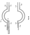
- FIG. 1 illustrates one portion of an example process for manufacturing a double-balloon catheter.
- the process begins with two balloons-an inner balloon 101A and a separate outer balloon 101B.
- a longitudinal cross-section of the two balloons 101A and 101B is provided in FIG. 1 .
- Each balloon 101A and 101B has opposite, open longitudinal ends 104A-D and a central radially expandable portion 107A and 107B.
- Each balloon also has a proximal reduced diameter portion 110A and 110B (e.g., neck portion), a distal reduced diameter portion 113A and 113B, and an inner surface 114A and 114B and outer surface 115A and 115B.
- the inner balloon 10 1 A is inserted within the outer balloon 101B to form a balloon assembly 102 that is further illustrated in FIG. 2 .
- the inner balloon 101A is at least partially deflated or radially compressed and the outer balloon 101B is at least partially inflated or radially expanded.
- the outer balloon 101B may be secured by its proximal reduced diameter portion 110B and/or the distal reduced diameter portion 113B to manufacturing equipment (not shown).
- the inner balloon 101A may be temporarily secured to other manufacturing equipment, such as a mandrel 117 (shown in FIG 2 ) to facilitate insertion into the outer balloon 101B.
- the inner balloon 101A is radially compressed by being twisted.
- the distal reduced diameter portion 113A can be twisted relative to the proximal reduced diameter portion 110A by the manufacturing equipment.
- a rigid guide such as the mandrel 117 can seal against the proximal reduced diameter 110A and the distal reduced diameter portion 113A, and the mandrel 117 can provide a pressure source (depicted in FIG. 2 ) that radially compresses the central radially expandable portion 107A of the inner balloon 101A.
- FIG 2 illustrates an example balloon assembly 102 formed by inserting the inner balloon 101A into the outer balloon 101B.
- the central radially expandable portion 107A of the inner balloon 101A is at least partially re-expanded, although re-expansion is not required.
- the example mandrel 117 can include a pressure source that either draws a vacuum to compress the central radially expandable portion 107A, or exerts pressure to expand the radially expandable portion 107A.
- the pressure source can be coupled to the interior of the inner balloon via a mandrel lumen 119 and mandrel orifices 121.
- the mandrel 117 can have a distal tip portion 124 that rotates relative to a body portion 127, and the distal tip portion 124 can be rotated to either twist and radially compress the inner balloon or untwist and radially expand the inner balloon 101A.
- the balloons 101A and 101B are bonded together to form the balloon assembly 102.
- Both of the proximal reduced diameter portions 110A and 110B and the distal reduced diameter portions 113A or 113B are bonded together by applying pressure to the outer surface 115A of the outer balloon 101B (e.g., with clamps 130A or 130B), such that a reduced diameter portion 110B and 113B of the outer balloon 101B is brought into contact with a corresponding reduced diameter portion 110A and 113A of the inner balloon 101A.
- the two balloons 101A and 101B are in contact, they and bonded with an adhesive or through application of thermal energy.
- thermal energy is applied directly, for example, by heating elements 133 in the mandrel 117 and/or clamps 130B.
- thermal energy is applied by a laser source 136, for example, through channel 139 in the clamp 130A to laser bond the inner balloon 101A and the outer balloon 101B together.
- a vacuum lumen 142 is disposed between the inner balloon 101A and the outer balloon 101B, and the balloons 101A and 101B are subsequently bonded together around the vacuum lumen 142.
- the vacuum lumen 142 can provide a way to evacuate any liquids or gases that escape from a chamber 144 defined by the inner balloon 101A.
- the vacuum lumen 142 can be used to evacuate cryotherapy fluid from the balloon assembly in the case of a rupture of the inner balloon 101A.
- the vacuum lumen 142 can also facilitate control of the space between the inner balloon 101A and the outer balloon 101B.
- a vacuum source can be applied to the vacuum lumen 142 in order to draw the outer balloon 101B against the inner balloon 101A, or a pressure source may be applied to force the outer balloon 101B away from the inner balloon 101A.
- regulating spacing between the inner balloon 101A and the outer balloon 101 B can have the effect of indirectly controlling temperature of the outer surface 115A of the outer balloon 101B.
- the inner balloon 101A and outer balloon 101B are bonded together and around the vacuum lumen 142 in a manner similar to that described with reference to FIG. 2 . That is, a reduced diameter portion 110B of the outer balloon 101B is brought into contact with a corresponding reduced diameter portion 110A of the inner balloon 101A and with the exterior of the vacuum lumen 142.
- the inner balloon 101A and outer balloon 101B are then bonded together (e.g., with adhesive or thermal or laser bonds).
- the inner balloon 101A and outer balloon 101B can be completely bonded together and sealed about the circumference of the corresponding reduced diameter portions 110 and 110B (or 113A and 113B).
- FIG. 4A is a cross-section showing additional details of an exemplary bond between a reduced diameter portion of the inner balloon ("inner balloon 101A") and a corresponding reduced diameter portion of the outer balloon (“outer balloon 101B").
- a vacuum lumen 142 is included between the inner balloon 101A and outer balloon 101 B; in other implementations, the vacuum lumen is omitted.
- heating elements 133 in the mandrel 117 and/or a corresponding clamp portion 130B provide thermal energy that softens or melts the material of the inner balloon 101A and outer balloon 101B such that the balloons 101A and 101B bond.
- a laser source 136 provides thermal energy to the inner balloon 101A and outer balloon 101B such that the balloons 101A and 101B are bonded together.
- the laser energy can be delivered via channel 139 in the clamp 130A.
- materials of the inner balloon 101A and the outer balloon 101B are selected such that the outer balloon 101B allows much of the laser energy to pass through, while the inner balloon 101A absorbs substantially all of the laser energy, thereby generating heat at the inner surface 114 of the outer balloon 101B and the outer surface 115A of the inner balloon 101A such that the balloons 101A and 101B bond.
- the clamps 130A, 130B or 130C are segmented, as shown, to facilitate radially expansion or compression capable of applying pressure to the outer balloon 101B around substantially all of the circumference.
- other techniques are used to bring the outer balloon 101 B into contact with the inner balloon 101A.
- some implementations can employ a vacuum source or pressure source to bring the balloons 101 A and 101B into contact.
- FIG. 4B illustrates a longitudinal cross-section of the balloon assembly 102A not being part of the present invention.
- the proximal reduced diameter portions 110A and 110B are bonded together, and the distal reduced diameter portions 113A and 113B are not bonded together.
- the invention required that, both reduced diameter portions 110A and 110B and 113A and 113B are bonded together. In other examples, only the distal reduced diameter portions 113A and 113B are bonded together (at this stage in the manufacturing process).
- the balloon assembly 102 is bonded to an elongate catheter shaft 146, as shown in FIG. 5 .
- the balloon assembly 102 is bonded to the elongate catheter shaft 146 in a similar manner as the balloons 101A and 101B are bonded together.
- the balloon assembly 102 can be secured against the elongate catheter shaft 146 via clamps 148, and once secured, a laser source 136 can be employed to laser bond the balloon assembly 102 to the elongate catheter shaft 146.
- the balloon assembly 102 can be secured to the elongate catheter shaft 146 with adhesive or by direct thermal bonding (e.g., with heat provided by a heating element).
- a mandrel (not shown in FIG. 5 ) is inserted into the balloon assembly 102 to facilitate bonding between the balloon assembly 102 and elongate catheter shaft 146.
- the elongate catheter shaft 146 includes a stiff region 151 that resists compression by the clamps to facilitate bonding without a mandrel.
- a guidewire lumen 154 is added.
- the guidewire lumen 154 includes a stiffening wire 155 that is removed after assembly. Steerable catheters that are not "over-the-wire" may omit the guidewire lumen 154.
- cryo fluid delivery apparatus 157 (shown in three dimensions rather than as a longitudinal cross section) is added.
- cryo fluid can be delivered from a source external to the catheter (shown in FIG. 7 ) via cryotherapy fluid delivery lumen 159 to a cooling chamber 144 inside the inner balloon 101A, where it is released to cool tissue that is adjacent to the outer balloon 101B.
- the cryo fluid is released from a coiled portion of the cryotherapy fluid deliver lumen 159 via orifices 162 where the cryo fluid undergoes a phase change, to a gas, within the cooling chamber 144 (the so-called Joule-Thomson effect).
- the gas can then be exhausted though an exhaust lumen 165, which, in some implementations, is simply the internal lumen formed by the body of the elongate catheter shaft 146.
- the catheter includes a pressure-sensing lumen 168 by which pressure inside the cooling chamber 144 can be sensed by devices external to the catheter.
- a thermocouple 171 or other temperature-sensing device can also be added to the catheter.
- the thermocouple 171 is integrated in the pressure-sensing lumen 168.
- the cryo fluid delivery apparatus 157 and guidewire lumen 154 may be preassembled and added to the catheter as a single assembly.
- the end of the catheter is sealed, and the distal reduced diameter portion 113B of the outer balloon 101B is bonded to the distal reduced diameter portion 113A of the inner balloon 101A, if this has not already been done.
- the distal regions of the inner balloon 101A and outer balloon 101B are laser bonded together.
- the distal portions of the outer balloon 101B and inner balloon 101A are laser bonded to the cryotherapy fluid deliver apparatus 157 and/or the guidewire lumen 154.
- an adhesive "plug" 174 is used to bond the inner balloon 101A to the guidewire lumen 154 and cryotherapy fluid deliver apparatus 157 and to seal off the distal portion of the cooling chamber 144.
- An example cryotherapy catheter 700 shown in FIG. 7 , includes the elongate member 146 with the inflatable balloon assembly 102 at a distal end 701.
- the balloon assembly 102 has an internal chamber 144 to which cryotherapy fluid is delivered to cool the internal chamber 144, the external surface 115B of the balloon assembly 102, and adjacent body tissue.
- a port device 702 is attached to a proximal end 704 of the elongate member 146.
- the port device 702 provides connections to various external equipment, including a cryotherapy fluid source 707 and an exhaust reservoir 710.
- the catheter's elongate member 146 has multiple internal lumens (not shown in FIG. 7 ).
- the internal lumens allow cryotherapy fluid to be delivered distally from the external cryotherapy fluid source 707 to the internal chamber 144 of the balloon assembly 102.
- the internal lumens of the elongate member 146 allow exhaust resulting from delivery of cryotherapy fluid to the internal chamber 144 to be delivered proximally from the internal chamber 144 to the external exhaust reservoir 720.
- the example catheter 700 shown in FIG. 7 is an over-the-wire type catheter.
- a catheter employs a guidewire 712 (and corresponding guidewire lumen 154, not shown in FIG. 7 ), which is shown as extending from the distal end 701 of the catheter 700.
- the guidewire 712 can be pre-positioned inside a patient's body; once the guidewire 712 is properly positioned, the balloon assembly 102 (in a deflated state) and the elongate member 146 can be routed over the guidewire 712 to a treatment site.
- the guidewire 712 and balloon assembly 102 portion of the catheter 700 can be advanced together to a treatment site inside a patient's body, with the guidewire portion 712 leading the balloon assembly 102 by some distance (e.g., several inches).
- some distance e.g., several inches.
- the balloon can then be advanced over the guidewire 712 until it also reaches the treatment site.
- the catheter 700 includes a manipulator 716, by which a medical practitioner can navigate the guidewire 712 and balloon assembly 102 through a patient's body to a treatment site.
- release of cryotherapy fluid into the cooling chamber 144 inflates the balloon assembly 102 to a shape similar to that shown in FIG. 7 .
- a pressure source 724 can be used to inflate the balloon assembly 102 independently of the release of cryotherapy fluid into the internal chamber 144 of the balloon assembly 102.
- the pressure source 724 can also be used to inflate an anchor member on the end of the guidewire 712 (not shown).
- the catheter 700 includes a connector 727 for connecting monitoring equipment 730.
- the monitoring equipment 730 can be used, for example, to monitor temperature or pressure at the distal end 701 of the catheter 700.
- various marker bands 733 are also disposed at the distal end 701 of the catheter 700.
- the marker bands 733 may be opaque when the catheter 700 is viewed by x-ray or other imaging techniques.
- the balloons 101A and 101B in the balloon assembly 102 are formed from a polymer including, but not limited to, polyolefin copolymer, polyester, polyethylene teraphthalate, polyethylene, polyether-block-amide, polyamide, polyimide, nylon, latex, or urethane.
- a polymer including, but not limited to, polyolefin copolymer, polyester, polyethylene teraphthalate, polyethylene, polyether-block-amide, polyamide, polyimide, nylon, latex, or urethane.
- certain implementations of the balloon assembly 102 include PEBAX® 7033 material (70D poly ether amide block).
- the individual balloons 101A and 101 B in the balloon assembly 102 can be made by blow-molding a polymer extrusion into the desired shape.
- one or both of the balloons 101A or 101B can be constructed to expand to a desired shape when pressurized without elastically deforming substantially beyond the desired shape.
- a number of ancillary processes can be used to affect the material properties of the balloons 101Aor 101B.
- the polymer extrusion can be exposed to gamma radiation which may alter the polymer infrastructure to provide uniform expansion during blow molding and additional burst strength when in use.
- a balloon 101A or 101 B can be exposed to a low temperature plasma field which may alter the surface properties to provide enhanced adhesion characteristics.
- Those skilled in the art will recognize that other materials and manufacturing processes may be used to provide a balloon assembly 102 suitable for use with the catheter.
Landscapes
- Health & Medical Sciences (AREA)
- Life Sciences & Earth Sciences (AREA)
- Heart & Thoracic Surgery (AREA)
- Animal Behavior & Ethology (AREA)
- General Health & Medical Sciences (AREA)
- Engineering & Computer Science (AREA)
- Biomedical Technology (AREA)
- Veterinary Medicine (AREA)
- Public Health (AREA)
- Pulmonology (AREA)
- Child & Adolescent Psychology (AREA)
- Biophysics (AREA)
- Anesthesiology (AREA)
- Hematology (AREA)
- Surgery (AREA)
- Nuclear Medicine, Radiotherapy & Molecular Imaging (AREA)
- Molecular Biology (AREA)
- Medical Informatics (AREA)
- Otolaryngology (AREA)
- Media Introduction/Drainage Providing Device (AREA)
- Surgical Instruments (AREA)
Applications Claiming Priority (2)
| Application Number | Priority Date | Filing Date | Title |
|---|---|---|---|
| US11/541,735 US8617149B2 (en) | 2006-10-02 | 2006-10-02 | Common bond, double-balloon catheter |
| PCT/US2007/080167 WO2008042890A1 (en) | 2006-10-02 | 2007-10-02 | Common bond, double-balloon catheter |
Publications (2)
| Publication Number | Publication Date |
|---|---|
| EP2076308A1 EP2076308A1 (en) | 2009-07-08 |
| EP2076308B1 true EP2076308B1 (en) | 2013-02-27 |
Family
ID=39032351
Family Applications (1)
| Application Number | Title | Priority Date | Filing Date |
|---|---|---|---|
| EP07843661A Active EP2076308B1 (en) | 2006-10-02 | 2007-10-02 | Common bond, double-balloon catheter |
Country Status (6)
| Country | Link |
|---|---|
| US (1) | US8617149B2 (enExample) |
| EP (1) | EP2076308B1 (enExample) |
| JP (1) | JP5225282B2 (enExample) |
| KR (1) | KR20090092757A (enExample) |
| CA (1) | CA2667101A1 (enExample) |
| WO (1) | WO2008042890A1 (enExample) |
Cited By (2)
| Publication number | Priority date | Publication date | Assignee | Title |
|---|---|---|---|---|
| US11400205B2 (en) | 2016-11-23 | 2022-08-02 | Biosense Webster (Israel) Ltd. | Balloon-in-balloon irrigation balloon catheter |
| US11813419B2 (en) | 2016-11-23 | 2023-11-14 | Biosense Webster (Israel) Ltd. | Double balloon catheter having a lobed inner balloon |
Families Citing this family (109)
| Publication number | Priority date | Publication date | Assignee | Title |
|---|---|---|---|---|
| US7756583B2 (en) | 2002-04-08 | 2010-07-13 | Ardian, Inc. | Methods and apparatus for intravascularly-induced neuromodulation |
| US8347891B2 (en) | 2002-04-08 | 2013-01-08 | Medtronic Ardian Luxembourg S.A.R.L. | Methods and apparatus for performing a non-continuous circumferential treatment of a body lumen |
| ES2564694T3 (es) | 2003-09-12 | 2016-03-28 | Vessix Vascular, Inc. | Sistema de remodelación y / o ablación excéntrica seleccionable de material ateroesclerótico |
| US9713730B2 (en) | 2004-09-10 | 2017-07-25 | Boston Scientific Scimed, Inc. | Apparatus and method for treatment of in-stent restenosis |
| US8396548B2 (en) | 2008-11-14 | 2013-03-12 | Vessix Vascular, Inc. | Selective drug delivery in a lumen |
| US8019435B2 (en) | 2006-05-02 | 2011-09-13 | Boston Scientific Scimed, Inc. | Control of arterial smooth muscle tone |
| ES2560006T3 (es) | 2006-10-18 | 2016-02-17 | Vessix Vascular, Inc. | Inducción de efectos de temperatura deseables sobre tejido corporal |
| EP2076193A4 (en) | 2006-10-18 | 2010-02-03 | Minnow Medical Inc | MATCHED RF-ENERGY AND ELECTRO-TISSUE CHARACTERIZATION FOR THE SELECTIVE TREATMENT OF TARGET TISSUE |
| WO2008049087A2 (en) | 2006-10-18 | 2008-04-24 | Minnow Medical, Inc. | System for inducing desirable temperature effects on body tissue |
| US20080312644A1 (en) | 2007-06-14 | 2008-12-18 | Boston Scientific Scimed, Inc. | Cryogenic balloon ablation instruments and systems |
| EP2265205B1 (en) * | 2008-03-13 | 2016-04-27 | Boston Scientific Scimed, Inc. | Cryo-ablation refrigerant distribution catheter |
| WO2009140067A1 (en) * | 2008-05-15 | 2009-11-19 | Boston Scientific Scimed, Inc. | Apparatus for cryogenically ablating tissue and adjusting cryogenic ablation regions |
| US10729464B1 (en) * | 2008-08-15 | 2020-08-04 | Viatechmd Llc | Cervical stabilization device |
| US10463530B2 (en) | 2008-08-15 | 2019-11-05 | Viatechmd Llc | Cervical stabilization device |
| US11607248B1 (en) | 2008-08-15 | 2023-03-21 | Via Techmd Llc | Cervical stabilization device |
| US10695126B2 (en) | 2008-10-06 | 2020-06-30 | Santa Anna Tech Llc | Catheter with a double balloon structure to generate and apply a heated ablative zone to tissue |
| KR20110104504A (ko) | 2008-11-17 | 2011-09-22 | 미노우 메디컬, 인코포레이티드 | 조직 토폴로지의 지식 여하에 따른 에너지의 선택적 축적 |
| US8382746B2 (en) * | 2008-11-21 | 2013-02-26 | C2 Therapeutics, Inc. | Cryogenic ablation system and method |
| US20110270238A1 (en) * | 2009-12-31 | 2011-11-03 | Raed Rizq | Compliant Cryoballoon Apparatus for Denervating Ostia of the Renal Arteries |
| CN103068330B (zh) | 2010-04-09 | 2016-06-29 | Vessix血管股份有限公司 | 用于治疗组织的功率发生和控制装置 |
| US9192790B2 (en) | 2010-04-14 | 2015-11-24 | Boston Scientific Scimed, Inc. | Focused ultrasonic renal denervation |
| US8473067B2 (en) | 2010-06-11 | 2013-06-25 | Boston Scientific Scimed, Inc. | Renal denervation and stimulation employing wireless vascular energy transfer arrangement |
| US9463062B2 (en) | 2010-07-30 | 2016-10-11 | Boston Scientific Scimed, Inc. | Cooled conductive balloon RF catheter for renal nerve ablation |
| US9084609B2 (en) | 2010-07-30 | 2015-07-21 | Boston Scientific Scime, Inc. | Spiral balloon catheter for renal nerve ablation |
| US9408661B2 (en) | 2010-07-30 | 2016-08-09 | Patrick A. Haverkost | RF electrodes on multiple flexible wires for renal nerve ablation |
| US9155589B2 (en) | 2010-07-30 | 2015-10-13 | Boston Scientific Scimed, Inc. | Sequential activation RF electrode set for renal nerve ablation |
| US9358365B2 (en) | 2010-07-30 | 2016-06-07 | Boston Scientific Scimed, Inc. | Precision electrode movement control for renal nerve ablation |
| CA2807277C (en) | 2010-08-05 | 2020-05-12 | Medtronic Ardian Luxembourg S.A.R.L. | Cryoablation apparatuses, systems, and methods for renal neuromodulation |
| US8974451B2 (en) | 2010-10-25 | 2015-03-10 | Boston Scientific Scimed, Inc. | Renal nerve ablation using conductive fluid jet and RF energy |
| US9066713B2 (en) | 2010-10-26 | 2015-06-30 | Medtronic Ardian Luxembourg S.A.R.L. | Neuromodulation cryotherapeutic devices and associated systems and methods |
| US9220558B2 (en) | 2010-10-27 | 2015-12-29 | Boston Scientific Scimed, Inc. | RF renal denervation catheter with multiple independent electrodes |
| US9028485B2 (en) | 2010-11-15 | 2015-05-12 | Boston Scientific Scimed, Inc. | Self-expanding cooling electrode for renal nerve ablation |
| US9668811B2 (en) | 2010-11-16 | 2017-06-06 | Boston Scientific Scimed, Inc. | Minimally invasive access for renal nerve ablation |
| US9089350B2 (en) | 2010-11-16 | 2015-07-28 | Boston Scientific Scimed, Inc. | Renal denervation catheter with RF electrode and integral contrast dye injection arrangement |
| US9326751B2 (en) | 2010-11-17 | 2016-05-03 | Boston Scientific Scimed, Inc. | Catheter guidance of external energy for renal denervation |
| US9060761B2 (en) | 2010-11-18 | 2015-06-23 | Boston Scientific Scime, Inc. | Catheter-focused magnetic field induced renal nerve ablation |
| US9192435B2 (en) | 2010-11-22 | 2015-11-24 | Boston Scientific Scimed, Inc. | Renal denervation catheter with cooled RF electrode |
| US9023034B2 (en) | 2010-11-22 | 2015-05-05 | Boston Scientific Scimed, Inc. | Renal ablation electrode with force-activatable conduction apparatus |
| US20120157993A1 (en) | 2010-12-15 | 2012-06-21 | Jenson Mark L | Bipolar Off-Wall Electrode Device for Renal Nerve Ablation |
| WO2012100095A1 (en) | 2011-01-19 | 2012-07-26 | Boston Scientific Scimed, Inc. | Guide-compatible large-electrode catheter for renal nerve ablation with reduced arterial injury |
| US12201340B2 (en) | 2011-03-25 | 2025-01-21 | Medtronic Cryocath Lp | Spray nozzle design for a catheter |
| US9439707B2 (en) * | 2011-03-25 | 2016-09-13 | Medtronic Cryocath Lp | Spray nozzle design for a catheter |
| EP2694150A1 (en) | 2011-04-08 | 2014-02-12 | Covidien LP | Iontophoresis drug delivery system and method for denervation of the renal sympathetic nerve and iontophoretic drug delivery |
| TW201242570A (en) | 2011-04-25 | 2012-11-01 | Medtronic Ardian Luxembourg | Apparatus and methods related to constrained deployment of cryogenic balloons for limited cryogenic ablation of vessel walls |
| WO2013013156A2 (en) | 2011-07-20 | 2013-01-24 | Boston Scientific Scimed, Inc. | Percutaneous devices and methods to visualize, target and ablate nerves |
| EP2734264B1 (en) | 2011-07-22 | 2018-11-21 | Boston Scientific Scimed, Inc. | Nerve modulation system with a nerve modulation element positionable in a helical guide |
| WO2013055826A1 (en) | 2011-10-10 | 2013-04-18 | Boston Scientific Scimed, Inc. | Medical devices including ablation electrodes |
| US9420955B2 (en) | 2011-10-11 | 2016-08-23 | Boston Scientific Scimed, Inc. | Intravascular temperature monitoring system and method |
| EP2765940B1 (en) | 2011-10-11 | 2015-08-26 | Boston Scientific Scimed, Inc. | Off-wall electrode device for nerve modulation |
| US9364284B2 (en) | 2011-10-12 | 2016-06-14 | Boston Scientific Scimed, Inc. | Method of making an off-wall spacer cage |
| EP2768563B1 (en) | 2011-10-18 | 2016-11-09 | Boston Scientific Scimed, Inc. | Deflectable medical devices |
| EP2768568B1 (en) | 2011-10-18 | 2020-05-06 | Boston Scientific Scimed, Inc. | Integrated crossing balloon catheter |
| US8951251B2 (en) | 2011-11-08 | 2015-02-10 | Boston Scientific Scimed, Inc. | Ostial renal nerve ablation |
| US9119600B2 (en) | 2011-11-15 | 2015-09-01 | Boston Scientific Scimed, Inc. | Device and methods for renal nerve modulation monitoring |
| US9119632B2 (en) | 2011-11-21 | 2015-09-01 | Boston Scientific Scimed, Inc. | Deflectable renal nerve ablation catheter |
| US9265969B2 (en) | 2011-12-21 | 2016-02-23 | Cardiac Pacemakers, Inc. | Methods for modulating cell function |
| AU2012358143B2 (en) | 2011-12-23 | 2015-06-11 | Boston Scientific Scimed, Inc. | Expandable balloon or an electrode pad with a heat sensing device |
| EP2797534A1 (en) | 2011-12-28 | 2014-11-05 | Boston Scientific Scimed, Inc. | Device and methods for nerve modulation using a novel ablation catheter with polymeric ablative elements |
| US9050106B2 (en) | 2011-12-29 | 2015-06-09 | Boston Scientific Scimed, Inc. | Off-wall electrode device and methods for nerve modulation |
| US9220556B2 (en) | 2012-01-27 | 2015-12-29 | Medtronic Cryocath Lp | Balloon design to enhance cooling uniformity |
| US9241752B2 (en) | 2012-04-27 | 2016-01-26 | Medtronic Ardian Luxembourg S.A.R.L. | Shafts with pressure relief in cryotherapeutic catheters and associated devices, systems, and methods |
| EP2840991B1 (en) | 2012-04-27 | 2019-05-15 | Medtronic Ardian Luxembourg S.à.r.l. | Cryotherapeutic devices for renal neuromodulation |
| WO2013169927A1 (en) | 2012-05-08 | 2013-11-14 | Boston Scientific Scimed, Inc. | Renal nerve modulation devices |
| CN104540465A (zh) | 2012-08-24 | 2015-04-22 | 波士顿科学西美德公司 | 带有含单独微孔隙区域的球囊的血管内导管 |
| US9173696B2 (en) | 2012-09-17 | 2015-11-03 | Boston Scientific Scimed, Inc. | Self-positioning electrode system and method for renal nerve modulation |
| US10549127B2 (en) | 2012-09-21 | 2020-02-04 | Boston Scientific Scimed, Inc. | Self-cooling ultrasound ablation catheter |
| WO2014047411A1 (en) | 2012-09-21 | 2014-03-27 | Boston Scientific Scimed, Inc. | System for nerve modulation and innocuous thermal gradient nerve block |
| EP2906135A2 (en) | 2012-10-10 | 2015-08-19 | Boston Scientific Scimed, Inc. | Renal nerve modulation devices and methods |
| US9956033B2 (en) | 2013-03-11 | 2018-05-01 | Boston Scientific Scimed, Inc. | Medical devices for modulating nerves |
| WO2014143571A1 (en) | 2013-03-11 | 2014-09-18 | Boston Scientific Scimed, Inc. | Medical devices for modulating nerves |
| US9808311B2 (en) | 2013-03-13 | 2017-11-07 | Boston Scientific Scimed, Inc. | Deflectable medical devices |
| US10265122B2 (en) | 2013-03-15 | 2019-04-23 | Boston Scientific Scimed, Inc. | Nerve ablation devices and related methods of use |
| US9827039B2 (en) | 2013-03-15 | 2017-11-28 | Boston Scientific Scimed, Inc. | Methods and apparatuses for remodeling tissue of or adjacent to a body passage |
| WO2014149690A2 (en) | 2013-03-15 | 2014-09-25 | Boston Scientific Scimed, Inc. | Medical devices and methods for treatment of hypertension that utilize impedance compensation |
| US9943365B2 (en) | 2013-06-21 | 2018-04-17 | Boston Scientific Scimed, Inc. | Renal denervation balloon catheter with ride along electrode support |
| WO2014205399A1 (en) | 2013-06-21 | 2014-12-24 | Boston Scientific Scimed, Inc. | Medical devices for renal nerve ablation having rotatable shafts |
| US9707036B2 (en) | 2013-06-25 | 2017-07-18 | Boston Scientific Scimed, Inc. | Devices and methods for nerve modulation using localized indifferent electrodes |
| AU2014284558B2 (en) | 2013-07-01 | 2017-08-17 | Boston Scientific Scimed, Inc. | Medical devices for renal nerve ablation |
| US10660698B2 (en) | 2013-07-11 | 2020-05-26 | Boston Scientific Scimed, Inc. | Devices and methods for nerve modulation |
| US10413357B2 (en) | 2013-07-11 | 2019-09-17 | Boston Scientific Scimed, Inc. | Medical device with stretchable electrode assemblies |
| WO2015010074A1 (en) | 2013-07-19 | 2015-01-22 | Boston Scientific Scimed, Inc. | Spiral bipolar electrode renal denervation balloon |
| EP3024406B1 (en) | 2013-07-22 | 2019-06-19 | Boston Scientific Scimed, Inc. | Medical devices for renal nerve ablation |
| EP3024405A1 (en) | 2013-07-22 | 2016-06-01 | Boston Scientific Scimed, Inc. | Renal nerve ablation catheter having twist balloon |
| JP6159888B2 (ja) | 2013-08-22 | 2017-07-05 | ボストン サイエンティフィック サイムド,インコーポレイテッドBoston Scientific Scimed,Inc. | 腎神経変調バルーンへの接着性を向上させたフレキシブル回路 |
| US9895194B2 (en) | 2013-09-04 | 2018-02-20 | Boston Scientific Scimed, Inc. | Radio frequency (RF) balloon catheter having flushing and cooling capability |
| EP3043733A1 (en) | 2013-09-13 | 2016-07-20 | Boston Scientific Scimed, Inc. | Ablation balloon with vapor deposited cover layer |
| US9687288B2 (en) | 2013-09-30 | 2017-06-27 | Arrinex, Inc. | Apparatus and methods for treating rhinitis |
| US11246654B2 (en) | 2013-10-14 | 2022-02-15 | Boston Scientific Scimed, Inc. | Flexible renal nerve ablation devices and related methods of use and manufacture |
| US9687166B2 (en) | 2013-10-14 | 2017-06-27 | Boston Scientific Scimed, Inc. | High resolution cardiac mapping electrode array catheter |
| US9770606B2 (en) | 2013-10-15 | 2017-09-26 | Boston Scientific Scimed, Inc. | Ultrasound ablation catheter with cooling infusion and centering basket |
| WO2015057584A1 (en) | 2013-10-15 | 2015-04-23 | Boston Scientific Scimed, Inc. | Medical device balloon |
| EP3057521B1 (en) | 2013-10-18 | 2020-03-25 | Boston Scientific Scimed, Inc. | Balloon catheters with flexible conducting wires |
| JP2016534842A (ja) | 2013-10-25 | 2016-11-10 | ボストン サイエンティフィック サイムド,インコーポレイテッドBoston Scientific Scimed,Inc. | 除神経フレックス回路における埋め込み熱電対 |
| CN105899157B (zh) | 2014-01-06 | 2019-08-09 | 波士顿科学国际有限公司 | 抗撕裂柔性电路组件 |
| US11000679B2 (en) | 2014-02-04 | 2021-05-11 | Boston Scientific Scimed, Inc. | Balloon protection and rewrapping devices and related methods of use |
| US9907609B2 (en) | 2014-02-04 | 2018-03-06 | Boston Scientific Scimed, Inc. | Alternative placement of thermal sensors on bipolar electrode |
| US10492842B2 (en) | 2014-03-07 | 2019-12-03 | Medtronic Ardian Luxembourg S.A.R.L. | Monitoring and controlling internally administered cryotherapy |
| US10709490B2 (en) | 2014-05-07 | 2020-07-14 | Medtronic Ardian Luxembourg S.A.R.L. | Catheter assemblies comprising a direct heating element for renal neuromodulation and associated systems and methods |
| US9763743B2 (en) | 2014-07-25 | 2017-09-19 | Arrinex, Inc. | Apparatus and method for treating rhinitis |
| US9414878B1 (en) | 2015-05-15 | 2016-08-16 | C2 Therapeutics, Inc. | Cryogenic balloon ablation system |
| EP3413822B1 (en) | 2016-02-11 | 2023-08-30 | Arrinex, Inc. | Device for image guided post-nasal nerve ablation |
| US12364537B2 (en) | 2016-05-02 | 2025-07-22 | Santa Anna Tech Llc | Catheter with a double balloon structure to generate and apply a heated ablative zone to tissue |
| US11331140B2 (en) | 2016-05-19 | 2022-05-17 | Aqua Heart, Inc. | Heated vapor ablation systems and methods for treating cardiac conditions |
| CN109414284B (zh) | 2016-05-20 | 2021-08-10 | 美国宾得公司 | 具有可旋转并且可平移的导管的低温消融系统 |
| EP3471638B1 (en) | 2016-06-15 | 2025-01-29 | Arrinex, Inc. | Devices for treating a lateral surface of a nasal cavity |
| US10939965B1 (en) | 2016-07-20 | 2021-03-09 | Arrinex, Inc. | Devices and methods for treating a nerve of the nasal cavity using image guidance |
| US11253312B2 (en) | 2016-10-17 | 2022-02-22 | Arrinex, Inc. | Integrated nasal nerve detector ablation-apparatus, nasal nerve locator, and methods of use |
| US11890044B2 (en) | 2016-12-09 | 2024-02-06 | St. Jude Medical, Cardiology Division, Inc. | Pulmonary vein isolation balloon catheter |
| JP7300999B2 (ja) | 2017-04-28 | 2023-06-30 | アリネックス, インコーポレイテッド | 鼻炎の治療において血管を位置特定するためのシステムおよび方法 |
Citations (1)
| Publication number | Priority date | Publication date | Assignee | Title |
|---|---|---|---|---|
| US20030060762A1 (en) * | 2001-09-27 | 2003-03-27 | Galil Medical Ltd. | Cryoplasty apparatus and method |
Family Cites Families (16)
| Publication number | Priority date | Publication date | Assignee | Title |
|---|---|---|---|---|
| US3173418A (en) | 1961-01-10 | 1965-03-16 | Ostap E Baran | Double-wall endotracheal cuff |
| US4763654A (en) * | 1986-09-10 | 1988-08-16 | Jang G David | Tandem independently inflatable/deflatable multiple diameter balloon angioplasty catheter systems and method of use |
| DK0420488T3 (da) | 1989-09-25 | 1993-08-30 | Schneider Usa Inc | Flerlags-ekstrusion som fremgangsmåde til fremstilling af angioplastik-balloner |
| US5195969A (en) | 1991-04-26 | 1993-03-23 | Boston Scientific Corporation | Co-extruded medical balloons and catheter using such balloons |
| US5569184A (en) | 1992-04-29 | 1996-10-29 | Cardiovascular Dynamics, Inc. | Delivery and balloon dilatation catheter and method of using |
| US5447497A (en) | 1992-08-06 | 1995-09-05 | Scimed Life Systems, Inc | Balloon catheter having nonlinear compliance curve and method of using |
| DE69433506T2 (de) | 1993-10-01 | 2004-06-24 | Boston Scientific Corp., Natick | Medizinische, thermoplastische elastomere enthaltende ballone |
| US5843116A (en) * | 1996-05-02 | 1998-12-01 | Cardiovascular Dynamics, Inc. | Focalized intraluminal balloons |
| US5868776A (en) | 1996-09-03 | 1999-02-09 | Ideas For Medicine, Inc. | Overlay dual balloon catheter and method for use thereof |
| US5868735A (en) | 1997-03-06 | 1999-02-09 | Scimed Life Systems, Inc. | Cryoplasty device and method |
| AU742942B2 (en) | 1997-04-07 | 2002-01-17 | Cook Urological Inc. | Back-up retention member drainage catheter |
| US5913813A (en) | 1997-07-24 | 1999-06-22 | Proxima Therapeutics, Inc. | Double-wall balloon catheter for treatment of proliferative tissue |
| US6905494B2 (en) * | 1998-03-31 | 2005-06-14 | Innercool Therapies, Inc. | Method and device for performing cooling- or cryo-therapies for, e.g., angioplasty with reduced restenosis or pulmonary vein cell necrosis to inhibit atrial fibrillation employing tissue protection |
| DK1158906T3 (da) | 1999-02-10 | 2008-12-08 | Swaminathan Jayaraman | Ballonkateter til kryoterapi |
| US6740191B2 (en) * | 2001-02-22 | 2004-05-25 | Medtronic Ave, Inc. | Through-transmission welding of catheter components |
| WO2006055941A1 (en) * | 2004-11-18 | 2006-05-26 | Cordis Corporation | Complex medical balloons |
-
2006
- 2006-10-02 US US11/541,735 patent/US8617149B2/en active Active
-
2007
- 2007-10-02 KR KR1020097007822A patent/KR20090092757A/ko not_active Withdrawn
- 2007-10-02 CA CA002667101A patent/CA2667101A1/en not_active Abandoned
- 2007-10-02 WO PCT/US2007/080167 patent/WO2008042890A1/en not_active Ceased
- 2007-10-02 JP JP2009530676A patent/JP5225282B2/ja active Active
- 2007-10-02 EP EP07843661A patent/EP2076308B1/en active Active
Patent Citations (1)
| Publication number | Priority date | Publication date | Assignee | Title |
|---|---|---|---|---|
| US20030060762A1 (en) * | 2001-09-27 | 2003-03-27 | Galil Medical Ltd. | Cryoplasty apparatus and method |
Cited By (3)
| Publication number | Priority date | Publication date | Assignee | Title |
|---|---|---|---|---|
| US11400205B2 (en) | 2016-11-23 | 2022-08-02 | Biosense Webster (Israel) Ltd. | Balloon-in-balloon irrigation balloon catheter |
| US11813419B2 (en) | 2016-11-23 | 2023-11-14 | Biosense Webster (Israel) Ltd. | Double balloon catheter having a lobed inner balloon |
| US11963715B2 (en) | 2016-11-23 | 2024-04-23 | Biosense Webster (Israel) Ltd. | Balloon-in-balloon irrigation balloon catheter |
Also Published As
| Publication number | Publication date |
|---|---|
| JP2010505470A (ja) | 2010-02-25 |
| US8617149B2 (en) | 2013-12-31 |
| EP2076308A1 (en) | 2009-07-08 |
| CA2667101A1 (en) | 2008-04-10 |
| JP5225282B2 (ja) | 2013-07-03 |
| KR20090092757A (ko) | 2009-09-01 |
| WO2008042890A1 (en) | 2008-04-10 |
| US20080171974A1 (en) | 2008-07-17 |
Similar Documents
| Publication | Publication Date | Title |
|---|---|---|
| EP2076308B1 (en) | Common bond, double-balloon catheter | |
| US8465481B2 (en) | Providing cryotherapy with a balloon catheter having a non-uniform thermal profile | |
| US8790300B2 (en) | Dual balloon catheter | |
| US8333757B2 (en) | Biasing a catheter balloon | |
| US8827952B2 (en) | Biasing mechanism for a balloon catheter | |
| US9888953B2 (en) | Nested balloon cryotherapy | |
| US7785289B2 (en) | Catheter with flexible, non-kinking elongate member | |
| US20230000536A1 (en) | Systems and methods to block or inhibit gas progression during spray cryotherapy | |
| US20180199981A1 (en) | Systems and methods to prevent or significantly inhibit gas progression during spray cryotherapy | |
| US20200129220A1 (en) | Cryoballoon for intravascular catheter system | |
| US20230346450A1 (en) | Cryoablation Devices And Related Methods | |
| WO2013133183A1 (ja) | バルーンカテーテル | |
| JP2025532432A (ja) | 低温アブレーション装置 | |
| KR20240044925A (ko) | 이중 풍선 카테터 및 그의 제조 방법 | |
| WO2019023185A1 (en) | METHOD FOR MANUFACTURING CRYOGENIC BALLOON FOR INTRAVASCULAR CATHETER SYSTEM | |
| WO2011146085A1 (en) | Rapid response balloon catheter |
Legal Events
| Date | Code | Title | Description |
|---|---|---|---|
| PUAI | Public reference made under article 153(3) epc to a published international application that has entered the european phase |
Free format text: ORIGINAL CODE: 0009012 |
|
| 17P | Request for examination filed |
Effective date: 20090428 |
|
| AK | Designated contracting states |
Kind code of ref document: A1 Designated state(s): AT BE BG CH CY CZ DE DK EE ES FI FR GB GR HU IE IS IT LI LT LU LV MC MT NL PL PT RO SE SI SK TR |
|
| 17Q | First examination report despatched |
Effective date: 20090827 |
|
| DAX | Request for extension of the european patent (deleted) | ||
| GRAP | Despatch of communication of intention to grant a patent |
Free format text: ORIGINAL CODE: EPIDOSNIGR1 |
|
| GRAS | Grant fee paid |
Free format text: ORIGINAL CODE: EPIDOSNIGR3 |
|
| GRAA | (expected) grant |
Free format text: ORIGINAL CODE: 0009210 |
|
| AK | Designated contracting states |
Kind code of ref document: B1 Designated state(s): AT BE BG CH CY CZ DE DK EE ES FI FR GB GR HU IE IS IT LI LT LU LV MC MT NL PL PT RO SE SI SK TR |
|
| REG | Reference to a national code |
Ref country code: GB Ref legal event code: FG4D |
|
| REG | Reference to a national code |
Ref country code: CH Ref legal event code: EP |
|
| REG | Reference to a national code |
Ref country code: AT Ref legal event code: REF Ref document number: 598163 Country of ref document: AT Kind code of ref document: T Effective date: 20130315 |
|
| REG | Reference to a national code |
Ref country code: IE Ref legal event code: FG4D |
|
| REG | Reference to a national code |
Ref country code: DE Ref legal event code: R096 Ref document number: 602007028800 Country of ref document: DE Effective date: 20130425 |
|
| REG | Reference to a national code |
Ref country code: NL Ref legal event code: T3 |
|
| REG | Reference to a national code |
Ref country code: AT Ref legal event code: MK05 Ref document number: 598163 Country of ref document: AT Kind code of ref document: T Effective date: 20130227 |
|
| REG | Reference to a national code |
Ref country code: LT Ref legal event code: MG4D |
|
| PG25 | Lapsed in a contracting state [announced via postgrant information from national office to epo] |
Ref country code: SE Free format text: LAPSE BECAUSE OF FAILURE TO SUBMIT A TRANSLATION OF THE DESCRIPTION OR TO PAY THE FEE WITHIN THE PRESCRIBED TIME-LIMIT Effective date: 20130227 Ref country code: BG Free format text: LAPSE BECAUSE OF FAILURE TO SUBMIT A TRANSLATION OF THE DESCRIPTION OR TO PAY THE FEE WITHIN THE PRESCRIBED TIME-LIMIT Effective date: 20130527 Ref country code: IS Free format text: LAPSE BECAUSE OF FAILURE TO SUBMIT A TRANSLATION OF THE DESCRIPTION OR TO PAY THE FEE WITHIN THE PRESCRIBED TIME-LIMIT Effective date: 20130627 Ref country code: LT Free format text: LAPSE BECAUSE OF FAILURE TO SUBMIT A TRANSLATION OF THE DESCRIPTION OR TO PAY THE FEE WITHIN THE PRESCRIBED TIME-LIMIT Effective date: 20130227 Ref country code: AT Free format text: LAPSE BECAUSE OF FAILURE TO SUBMIT A TRANSLATION OF THE DESCRIPTION OR TO PAY THE FEE WITHIN THE PRESCRIBED TIME-LIMIT Effective date: 20130227 Ref country code: ES Free format text: LAPSE BECAUSE OF FAILURE TO SUBMIT A TRANSLATION OF THE DESCRIPTION OR TO PAY THE FEE WITHIN THE PRESCRIBED TIME-LIMIT Effective date: 20130607 |
|
| PG25 | Lapsed in a contracting state [announced via postgrant information from national office to epo] |
Ref country code: PT Free format text: LAPSE BECAUSE OF FAILURE TO SUBMIT A TRANSLATION OF THE DESCRIPTION OR TO PAY THE FEE WITHIN THE PRESCRIBED TIME-LIMIT Effective date: 20130627 Ref country code: PL Free format text: LAPSE BECAUSE OF FAILURE TO SUBMIT A TRANSLATION OF THE DESCRIPTION OR TO PAY THE FEE WITHIN THE PRESCRIBED TIME-LIMIT Effective date: 20130227 Ref country code: SI Free format text: LAPSE BECAUSE OF FAILURE TO SUBMIT A TRANSLATION OF THE DESCRIPTION OR TO PAY THE FEE WITHIN THE PRESCRIBED TIME-LIMIT Effective date: 20130227 Ref country code: FI Free format text: LAPSE BECAUSE OF FAILURE TO SUBMIT A TRANSLATION OF THE DESCRIPTION OR TO PAY THE FEE WITHIN THE PRESCRIBED TIME-LIMIT Effective date: 20130227 Ref country code: BE Free format text: LAPSE BECAUSE OF FAILURE TO SUBMIT A TRANSLATION OF THE DESCRIPTION OR TO PAY THE FEE WITHIN THE PRESCRIBED TIME-LIMIT Effective date: 20130227 Ref country code: LV Free format text: LAPSE BECAUSE OF FAILURE TO SUBMIT A TRANSLATION OF THE DESCRIPTION OR TO PAY THE FEE WITHIN THE PRESCRIBED TIME-LIMIT Effective date: 20130227 Ref country code: GR Free format text: LAPSE BECAUSE OF FAILURE TO SUBMIT A TRANSLATION OF THE DESCRIPTION OR TO PAY THE FEE WITHIN THE PRESCRIBED TIME-LIMIT Effective date: 20130528 |
|
| PG25 | Lapsed in a contracting state [announced via postgrant information from national office to epo] |
Ref country code: CZ Free format text: LAPSE BECAUSE OF FAILURE TO SUBMIT A TRANSLATION OF THE DESCRIPTION OR TO PAY THE FEE WITHIN THE PRESCRIBED TIME-LIMIT Effective date: 20130227 Ref country code: RO Free format text: LAPSE BECAUSE OF FAILURE TO SUBMIT A TRANSLATION OF THE DESCRIPTION OR TO PAY THE FEE WITHIN THE PRESCRIBED TIME-LIMIT Effective date: 20130227 Ref country code: DK Free format text: LAPSE BECAUSE OF FAILURE TO SUBMIT A TRANSLATION OF THE DESCRIPTION OR TO PAY THE FEE WITHIN THE PRESCRIBED TIME-LIMIT Effective date: 20130227 Ref country code: EE Free format text: LAPSE BECAUSE OF FAILURE TO SUBMIT A TRANSLATION OF THE DESCRIPTION OR TO PAY THE FEE WITHIN THE PRESCRIBED TIME-LIMIT Effective date: 20130227 Ref country code: SK Free format text: LAPSE BECAUSE OF FAILURE TO SUBMIT A TRANSLATION OF THE DESCRIPTION OR TO PAY THE FEE WITHIN THE PRESCRIBED TIME-LIMIT Effective date: 20130227 |
|
| PG25 | Lapsed in a contracting state [announced via postgrant information from national office to epo] |
Ref country code: CY Free format text: LAPSE BECAUSE OF FAILURE TO SUBMIT A TRANSLATION OF THE DESCRIPTION OR TO PAY THE FEE WITHIN THE PRESCRIBED TIME-LIMIT Effective date: 20130227 |
|
| PG25 | Lapsed in a contracting state [announced via postgrant information from national office to epo] |
Ref country code: IT Free format text: LAPSE BECAUSE OF FAILURE TO SUBMIT A TRANSLATION OF THE DESCRIPTION OR TO PAY THE FEE WITHIN THE PRESCRIBED TIME-LIMIT Effective date: 20130227 |
|
| PLBE | No opposition filed within time limit |
Free format text: ORIGINAL CODE: 0009261 |
|
| STAA | Information on the status of an ep patent application or granted ep patent |
Free format text: STATUS: NO OPPOSITION FILED WITHIN TIME LIMIT |
|
| 26N | No opposition filed |
Effective date: 20131128 |
|
| REG | Reference to a national code |
Ref country code: DE Ref legal event code: R097 Ref document number: 602007028800 Country of ref document: DE Effective date: 20131128 |
|
| PG25 | Lapsed in a contracting state [announced via postgrant information from national office to epo] |
Ref country code: MC Free format text: LAPSE BECAUSE OF FAILURE TO SUBMIT A TRANSLATION OF THE DESCRIPTION OR TO PAY THE FEE WITHIN THE PRESCRIBED TIME-LIMIT Effective date: 20130227 |
|
| REG | Reference to a national code |
Ref country code: CH Ref legal event code: PL |
|
| REG | Reference to a national code |
Ref country code: FR Ref legal event code: CA Effective date: 20140513 |
|
| GBPC | Gb: european patent ceased through non-payment of renewal fee |
Effective date: 20131002 |
|
| PG25 | Lapsed in a contracting state [announced via postgrant information from national office to epo] |
Ref country code: CH Free format text: LAPSE BECAUSE OF NON-PAYMENT OF DUE FEES Effective date: 20131031 Ref country code: GB Free format text: LAPSE BECAUSE OF NON-PAYMENT OF DUE FEES Effective date: 20131002 Ref country code: LI Free format text: LAPSE BECAUSE OF NON-PAYMENT OF DUE FEES Effective date: 20131031 |
|
| REG | Reference to a national code |
Ref country code: DE Ref legal event code: R082 Ref document number: 602007028800 Country of ref document: DE Representative=s name: VOSSIUS & PARTNER PATENTANWAELTE RECHTSANWAELT, DE |
|
| REG | Reference to a national code |
Ref country code: DE Ref legal event code: R081 Ref document number: 602007028800 Country of ref document: DE Owner name: BOSTON SCIENTIFIC LIMITED, BM Free format text: FORMER OWNER: BOSTON SCIENTIFIC LIMITED, CHRIST CHURCH, BB Effective date: 20150202 Ref country code: DE Ref legal event code: R082 Ref document number: 602007028800 Country of ref document: DE Representative=s name: VOSSIUS & PARTNER PATENTANWAELTE RECHTSANWAELT, DE Effective date: 20150202 |
|
| PG25 | Lapsed in a contracting state [announced via postgrant information from national office to epo] |
Ref country code: TR Free format text: LAPSE BECAUSE OF FAILURE TO SUBMIT A TRANSLATION OF THE DESCRIPTION OR TO PAY THE FEE WITHIN THE PRESCRIBED TIME-LIMIT Effective date: 20130227 |
|
| PG25 | Lapsed in a contracting state [announced via postgrant information from national office to epo] |
Ref country code: LU Free format text: LAPSE BECAUSE OF NON-PAYMENT OF DUE FEES Effective date: 20131002 Ref country code: HU Free format text: LAPSE BECAUSE OF FAILURE TO SUBMIT A TRANSLATION OF THE DESCRIPTION OR TO PAY THE FEE WITHIN THE PRESCRIBED TIME-LIMIT; INVALID AB INITIO Effective date: 20071002 |
|
| PG25 | Lapsed in a contracting state [announced via postgrant information from national office to epo] |
Ref country code: MT Free format text: LAPSE BECAUSE OF FAILURE TO SUBMIT A TRANSLATION OF THE DESCRIPTION OR TO PAY THE FEE WITHIN THE PRESCRIBED TIME-LIMIT Effective date: 20130227 |
|
| REG | Reference to a national code |
Ref country code: FR Ref legal event code: PLFP Year of fee payment: 10 |
|
| REG | Reference to a national code |
Ref country code: FR Ref legal event code: PLFP Year of fee payment: 11 |
|
| REG | Reference to a national code |
Ref country code: FR Ref legal event code: PLFP Year of fee payment: 12 |
|
| REG | Reference to a national code |
Ref country code: DE Ref legal event code: R081 Ref document number: 602007028800 Country of ref document: DE Owner name: BOSTON SCIENTIFIC MEDICAL DEVICE LIMITED, IE Free format text: FORMER OWNER: BOSTON SCIENTIFIC LIMITED, HAMILTON, BM |
|
| REG | Reference to a national code |
Ref country code: FR Ref legal event code: PLFP Year of fee payment: 16 |
|
| REG | Reference to a national code |
Ref country code: NL Ref legal event code: PD Owner name: BOSTON SCIENTIFIC MEDICAL DEVICE LIMITED; IE Free format text: DETAILS ASSIGNMENT: CHANGE OF OWNER(S), ASSIGNMENT; FORMER OWNER NAME: BOSTON SCIENTIFIC LIMITED Effective date: 20230929 |
|
| PGFP | Annual fee paid to national office [announced via postgrant information from national office to epo] |
Ref country code: DE Payment date: 20240919 Year of fee payment: 18 |
|
| PGFP | Annual fee paid to national office [announced via postgrant information from national office to epo] |
Ref country code: NL Payment date: 20250923 Year of fee payment: 19 |
|
| PGFP | Annual fee paid to national office [announced via postgrant information from national office to epo] |
Ref country code: FR Payment date: 20250924 Year of fee payment: 19 |
|
| PGFP | Annual fee paid to national office [announced via postgrant information from national office to epo] |
Ref country code: IE Payment date: 20250925 Year of fee payment: 19 |