EP2075652B1 - Antriebs- und Übertragungsorgan für einen Hemmungsmechanimus, damit ausgestattete Platte und Hemmung und mit diesen ausgestattetes Uhrwerk - Google Patents
Antriebs- und Übertragungsorgan für einen Hemmungsmechanimus, damit ausgestattete Platte und Hemmung und mit diesen ausgestattetes Uhrwerk Download PDFInfo
- Publication number
- EP2075652B1 EP2075652B1 EP20070025169 EP07025169A EP2075652B1 EP 2075652 B1 EP2075652 B1 EP 2075652B1 EP 20070025169 EP20070025169 EP 20070025169 EP 07025169 A EP07025169 A EP 07025169A EP 2075652 B1 EP2075652 B1 EP 2075652B1
- Authority
- EP
- European Patent Office
- Prior art keywords
- driving
- roller table
- transmitting element
- anchor
- plate
- Prior art date
- Legal status (The legal status is an assumption and is not a legal conclusion. Google has not performed a legal analysis and makes no representation as to the accuracy of the status listed.)
- Active
Links
- 230000005540 biological transmission Effects 0.000 title description 58
- 230000003993 interaction Effects 0.000 claims description 11
- 239000002210 silicon-based material Substances 0.000 claims description 9
- 239000000463 material Substances 0.000 claims description 6
- 230000001747 exhibiting effect Effects 0.000 claims 1
- PXHVJJICTQNCMI-UHFFFAOYSA-N Nickel Chemical compound [Ni] PXHVJJICTQNCMI-UHFFFAOYSA-N 0.000 description 2
- 238000004519 manufacturing process Methods 0.000 description 2
- 239000002184 metal Substances 0.000 description 2
- 229910052751 metal Inorganic materials 0.000 description 2
- 238000000034 method Methods 0.000 description 2
- 241001272720 Medialuna californiensis Species 0.000 description 1
- 229910000831 Steel Inorganic materials 0.000 description 1
- 210000003423 ankle Anatomy 0.000 description 1
- 239000002223 garnet Substances 0.000 description 1
- 238000003780 insertion Methods 0.000 description 1
- 230000037431 insertion Effects 0.000 description 1
- 238000005461 lubrication Methods 0.000 description 1
- 238000012423 maintenance Methods 0.000 description 1
- 229910052759 nickel Inorganic materials 0.000 description 1
- 230000010355 oscillation Effects 0.000 description 1
- 239000010979 ruby Substances 0.000 description 1
- 229910001750 ruby Inorganic materials 0.000 description 1
- 239000010959 steel Substances 0.000 description 1
Images


Classifications
-
- G—PHYSICS
- G04—HOROLOGY
- G04B—MECHANICALLY-DRIVEN CLOCKS OR WATCHES; MECHANICAL PARTS OF CLOCKS OR WATCHES IN GENERAL; TIME PIECES USING THE POSITION OF THE SUN, MOON OR STARS
- G04B15/00—Escapements
- G04B15/14—Component parts or constructional details, e.g. construction of the lever or the escape wheel
-
- G—PHYSICS
- G04—HOROLOGY
- G04B—MECHANICALLY-DRIVEN CLOCKS OR WATCHES; MECHANICAL PARTS OF CLOCKS OR WATCHES IN GENERAL; TIME PIECES USING THE POSITION OF THE SUN, MOON OR STARS
- G04B17/00—Mechanisms for stabilising frequency
- G04B17/04—Oscillators acting by spring tension
- G04B17/06—Oscillators with hairsprings, e.g. balance
Definitions
- the present invention relates to watch movements and more particularly to escapements. It aims in particular a drive and transmission member for, on the one hand, driving the escape anchor when it rotates with the driven plate on the balance shaft and, secondly, transmit to the plateau a pulse from the anchor. It also aims a tray comprising such a drive and transmission member. It also aims an exhaust with such a drive member and transmission and / or such a tray. Finally, it relates to a timepiece comprising such a drive and transmission member and / or such a plate and / or such an exhaust.
- an anchor escapement comprises a plate, single or double, driven on the axis of the balance.
- a plateau pin is driven on the underside of the board. In the presence of a double plateau, it is hunted on the underside of the large plateau.
- the tray anchor may also be placed in an elastic clamping portion of the tray, as described in the document DE 482 913 .
- the plateau peg is a piece, generally ruby or garnet, having an ellipse or half-moon or triangular shape, and which cooperates, in use, with the fork of the anchor.
- the balance shaft rotates in one direction and drives the plate in rotation.
- the plateau pin driven on the plate, rotates with it and cooperates with one of the horns of the fork to drive the anchor in a rotational movement about the axis of the anchor.
- one of its lifts releases a tooth of the escape wheel which starts to rotate.
- this same tooth imparts an impulse to the anchor, via the same lifted.
- the fork of the anchor which is still in contact with the plateau pin, communicates its impulse to said plateau pin. This transmits the impulse to the plate, which in turn transmits it to the balance shaft on which it is driven.
- the same functions occur inversely when the balance shaft is rotated in the other direction.
- the plateau pin plays two roles: on the one hand it rotates with the plate and drives the anchor in rotation to release the escape wheel, and on the other hand it transmits an impulse from the anchor to the plate. It therefore has a rotational drive function and a power transmission function.
- An object of the present invention is to provide a drive and transmission member for an escapement, which can fulfill the function of rotating the anchor and the energy transmission function of the anchor to the plate and to the balance shaft, during operation of the exhaust, and which can be made of a silicon-based material or other brittle material.
- the invention relates to a drive and transmission member for an escapement of a timepiece, said escapement comprising an escape wheel, an anchor and at least one tray driven on an axis. beam, said drive member and transmission being intended firstly to rotate said anchor when it rotates with said plate and secondly to transmit a pulse of said anchor to said plate.
- Said drive and transmission member comprises an elastic clamping means adapted to act in a clamping plane and intended to be arranged, in use, such that said clamping plane is substantially perpendicular to said balance shaft, and comprises a means of interaction extending from said clamping means and for interacting with said anchor to drive it.
- Said drive and transmission member is characterized in that it consists of a one-piece piece made of a material having no plastic field.
- the elastic clamping means is a split ring and the interaction means is a lug extending radially from said ring.
- the invention relates to a plate for an anchor escapement, said plate comprising a central hole intended to be traversed by a balance shaft to rigidly fix said plate to said balance shaft.
- Said plate comprises a drive and transmission member according to the first aspect of the invention and holding means for maintaining the angular position of said drive member and transmission.
- said plate further comprises a flange extending around said central hole.
- the invention relates to an anchor escapement, of the type comprising an escape wheel, an anchor and at least one plate, which comprises a drive and transmission member according to the first aspect and / or a tray according to the second aspect.
- the invention relates to a timepiece, in particular a watch, comprising a drive and transmission member according to the first aspect and / or a plate according to the second aspect and / or an anchor escapement according to the third aspect.
- a first embodiment of a drive and transmission member 10 having an elastic clamping means and an interaction means.
- the elastic clamping means is in the form of a ring 20 having an axis 100, an inner face 22 and an outer face 32, and open by a slot 30.
- a lug 40 extends radially from said outer face 32, diametrically opposite to the slot 30.
- the slot 30 is axial. She could be oblique. The presence of the slot 30 imparts elasticity to the ring 20.
- the lug 40 and the slot 30 define a first direction 11 of the drive and transmission member 10, which forms with the axis 100 of the ring 20 a plane of symmetry for the drive member and transmission 10.
- the plane of the ring 20, perpendicular to the axis 100, defines an elastic clamping plane.
- the inner face 22 of the ring 20 has two portions 26 adjacent the slot 30 and a portion 28 diametrically opposed to the slot 30. It also comprises two recessed portions 24 which are each located between one of the adjacent portions 26 and the opposite portion 28. The two recessed portions 24 are spaced from the axis 100 of a radius which is slightly greater than the common radius of the other three portions 26, 26, 28.
- the lug 40 has a shape that tapers from its end in connection with the outer surface 32 of the ring 20 towards its free end.
- the lug 40 has a substantially triangular profile, its free end having an end face 46 substantially flat and perpendicular to the first direction 11.
- the lug 40 has two lateral faces 44 connecting the face of end 46 to the outer face 32 of the ring 20.
- the junction between each of the side faces 44 and the end face 46 consists of an edge 48 which is preferably slightly rounded.
- FIG. 2 there is shown a second embodiment of a drive and transmission member 50, which differs from the first embodiment of the drive and transmission member 10 in that the lug 40 is provided with a through hole 54 extending in a second direction 12 which intersects the clamping plane of the ring 20.
- the second direction 12 is parallel to the axis 100 of the ring 20.
- the through hole 54 is disposed near the free end of the lug 40.
- the lug 40 of the drive and transmission member 50 according to the second embodiment may have narrow lateral faces 42, similarly to the lug 40 of the drive and transmission member 10 according to the first embodiment. This gives the same general shape to the drive and transmission members 10, 50 according to the two embodiments. It is thus possible to implement common manufacturing steps for the two embodiments of the drive and transmission member 10, 50, by providing an additional manufacturing step to make the through hole 54 for the body drive and transmission 50 according to the second embodiment.
- the drive and transmission member 10, 50 is made of a material that does not have a plastic field, for example a silicon-based material.
- a material that does not have a plastic field for example a silicon-based material.
- the ring 20 and the lug 40 that it carries are made in one piece.
- the figure 3 illustrates a plate 60 according to a first embodiment equipped with a drive and transmission member 10 according to the first embodiment.
- the plate 60 has a central hole 62 by means of which it is driven, in use, on a balance shaft 2, in order to achieve a rigid attachment of said plate 60 on said rocker shaft 2.
- the ring 20 of the drive and transmission member 10 is installed on the plate 60 around the balance shaft 2.
- the balance shaft 2 is shown in broken lines to prevent part of the ring 20 is hidden.
- the ring 20 is held in place by the presence of the slot 30 which allows it to ensure, in use, a resilient clamping on the balance shaft 2, which avoids a possible sliding of the ring 20 in the axial direction 100.
- the contact between the inner face 22 and the balance shaft 2 is only on the three portions which are not not recessed, that is to say on the two portions 26 adjacent the slot 30 and the portion 28 diametrically opposite the slot 30.
- Such arrangement in three contact zones improves the elastic clamping of the ring 20 on the balance shaft.
- the figure 4 illustrates a plate 70 according to a second embodiment equipped with a drive and transmission member 50 according to the second embodiment.
- the plate 70 has a central hole 72 by means of which it is driven, in use, on the balance shaft (not shown).
- the plate 70 further comprises an annular rim 74 which extends around the central hole 72 in a direction perpendicular to the plane of the plate 70. The presence of the rim 74 makes it possible to increase the contact area between the plate 70 and the balance shaft.
- the flange 74 also has a support function for the drive and transmission member 50. Indeed, the ring 20 of the drive and transmission member 50 is installed on the plate 70 around the flange 74.
- the angular holding of the drive and transmission member 10, 50 is achieved by holding means 4, 4, 6 of the plate 60, 70.
- a first embodiment of the holding means is illustrated on the figure 3 , in relation with a plate 60 according to the first embodiment and a drive and transmission member according to the first embodiment 10.
- Said holding means consist of two studs 4, 4 fixed on the face of the plate 60 which receives the drive and transmission member 10.
- the pads 4, 4 are arranged on the face of the plate 60 so that the lug 40 is immobilized between them when, in use, the ring 20 is in position around the axis of pendulum 2.
- the lateral faces 42 of the lug 40 are tightened in the zone of contact with the two pads 4, 4, so that said pads 4, 4 do not interfere with the cooperation of the free end of the lug 40 with the anchor during operation of the exhaust which will be described later in reference to Figures 5 and 6 .
- This first embodiment of the holding means is also compatible with a plate 70 according to the second embodiment, although such a variant is not shown in the figures for the sake of simplification.
- the ring 20 is, in use, immobilized against the rim 74 of the plate 70 by the studs 4, 4.
- FIG. figure 4 A second embodiment of the holding means, particularly adapted to the drive and transmission member 50 according to the second embodiment, is illustrated in FIG. figure 4 , in relation to a plate 70 according to the second embodiment.
- Said holding means consist of a single stud 6 fixed on the face of the plate 70 which receives the drive and transmission member 50.
- the stud 6 is disposed on the face of the plate 70 so that the pin 40 is immobilized by insertion of this stud 6 into the through hole 54 when, in use, the ring 20 is in position around the rim 74 of the plate 70.
- the diameter of the stud 6 is adjusted to the diameter of the through hole 54 so that the stud 6 does not exert stress in the lug 40 of the drive and transmission member 50.
- This second embodiment of the holding means is also compatible with a plate 60 according to the first embodiment, although such a variant is not shown in the figures for the sake of simplification.
- the ring 20 is, in use, immobilized directly against the balance shaft 2 by the stud 6.
- the plate 60, 70 is preferably made of metal, for example steel or nickel.
- the plate 60, 70 and the pads 4, 4, 6 are made in one piece. More preferably, the pads 4, 4, 6 are obtained by galvanic growth by means of a process known as the LIGA process.
- FIGS. 5 and 6 illustrate two configurations of an exhaust according to the third aspect of the invention during its operation. They show an anchor escapement 80 comprising, in known manner, an escape wheel 82 with teeth 822 and an anchor 84 rotatable about an anchor axis 806. The oscillation movement of the anchor 84 around the anchor axis 806 is limited by two stops 802, 804.
- the anchor 84 comprises, in known manner, a stinger which is not shown to simplify the figure and a fork 840 carried by a rod 842
- the fork 840 of the anchor 84 has two horns 844, 846 and the other end of the anchor 84 has two lifts 848.
- the exhaust 80 further comprises a plate 60 according to the first embodiment, driven on a balance shaft 2 and provided with a drive and transmission member 10 according to the first aspect of the invention, which comprises a ring 20 and a lug 40 immobilized on the plate 60 by two studs 4, 4 as described with reference to the figure 3 .
- the balance shaft 2 rotates in the direction indicated by the arrow 200.
- the plate 60 driven on the balance shaft 2, rotates in the same direction.
- the drive and transmission member 10, immobilized on the plate 60 by means of the studs 4, 4, rotates with it, until it meets the one 844 of the horns 844, 846 of the fork 840 and causes it to rotate, thereby rotating the anchor 84 about the anchor axis 806.
- one of the lifts 848 releases the tooth 822, which leaves turn the escape wheel 82.
- the tooth 822 transmits a pulse from the escape wheel 82 to the anchor 84, which transmits it, via the drive member and 10, the plate 60 and the balance shaft 2 on which is driven said plate 60.
- the cooperation between the lug 40 and the respective horns 844, 846 of the fork 840 is formed by the ridges 48 of the lug 40.
- the contact between the ridges 48 and horns 844, 846 is improved.
- the lug 40 of the drive and transmission member 10 advantageously fulfills the conventional functions of the plateau pin of a conventional exhaust.
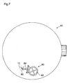
- the figure 7 schematically illustrates a timepiece 90, typically a watch, with an exhaust 80 such as that just described with reference to Figures 5 and 6 , comprising an escape wheel 82, an anchor 84, a plate 60 and a drive and transmission member 10.
- the exhaust 80 and the timepiece 90 according to the invention could comprise a plate 60 according to the first embodiment and provided with a drive and transmission member 50 according to the second embodiment, or a plate 70 according to the second embodiment and provided with a drive and transmission member 10 according to the first embodiment, or a plate 70 according to the second embodiment and provided with a drive member and transmission 50 according to the second embodiment.
- the invention is not limited to the embodiments that have been illustrated in the figures and covers alternative embodiments within the reach of those skilled in the art without departing from the scope defined by the appended claims.
- the end face 46 of the lug 40 of the drive and transmission member could be concave or convex instead of being flat.
- the resilient clamping means could have a shape different from that of a split ring, and the clamping could be performed on two points instead of three points.
Landscapes
- Physics & Mathematics (AREA)
- General Physics & Mathematics (AREA)
- Mechanical Operated Clutches (AREA)
- Gears, Cams (AREA)
Claims (18)
- Antriebs- und Übertragungsorgan (10, 50) für eine Hemmung (80) einer Uhr (90), welche ein Hemmungsrad (82), einen Anker (84) und mindestens eine Hebelscheibe (60, 70), die auf eine Unruhwelle (2) aufgepresst ist, aufweist, wobei das Antriebs- und Übertragungsorgan (10, 50) dazu bestimmt ist, einerseits den Anker (84) in Drehung zu versetzen, wenn es mit der Hebelscheibe (60, 70) rotiert, und andererseits einen Impuls des Ankers (84) auf die Hebelscheibe (60, 70) zu übertragen,
wobei das Antriebs- und Übertragungsorgan (10, 50) ein elastisches Klemmmittel (20), das geeignet ist, in einer Klemmebene zu wirken, und dazu bestimmt ist, im Betrieb derart angeordnet zu werden, dass die Klemmebene im Wesentlichen senkrecht zu der Unruhwelle (2) ist, und ein Interaktionsmittel (40), das sich von dem Klemmmittel (20) aus erstreckt und dazu bestimmt ist, mit dem Anker (84) zusammenzuwirken, um diesen anzutreiben, aufweist,
dadurch gekennzeichnet, dass es aus einem einstückigen Teil besteht, das aus einem Material hergestellt ist, das keinen plastischen Bereich aufweist. - Antriebs- und Übertragungsorgan (10, 50) nach Anspruch 1, wobei das Klemmmittel (20) als ein elastischer Ring (20) ausgebildet ist.
- Antriebs- und Übertragungsorgan (10, 50) nach Anspruch 2, wobei der Ring (20) durch einen Spalt (30) geöffnet ist.
- Antriebs- und Übertragungsorgan (10, 50) nach Anspruch 3, wobei der Spalt (30) und das Interaktionsmittel (40) diametral gegenüberliegend bezüglich der Achse (100) des Ringes (20) sind.
- Antriebs- und Übertragungsorgan (10, 50) nach einem der Ansprüche 2 bis 4, wobei der Ring (20) eine Innenseite (22) aufweist, welche zwei zurückspringende Abschnitte (24) aufweist.
- Antriebs- und Übertragungsorgan (10, 50) nach Anspruch 5 und Anspruch 4, wobei jeder zurückspringende Abschnitt (24) zwischen dem Spalt (30) und dem Interaktionsmittel (40) positioniert ist.
- Antriebs- und Übertragungsorgan (10, 50) nach einem der Ansprüche 1 bis 6, wobei das Interaktionsmittel (40) eine Form hat, die sich mit zunehmendem Abstand von dem Klemmmittel (20) erweitert.
- Antriebs- und Übertragungsorgan (10, 50) nach einem der Ansprüche 1 bis 7, wobei das Interaktionsmittel (40) ein Durchgangsloch (54) aufweist, das sich entlang einer Richtung (12) erstreckt, welche die Klemmebene schneidet.
- Antriebs- und Übertragungsorgan (10, 50) nach einem der Ansprüche 1 bis 8, wobei das Material ein Material auf Siliziumbasis ist.
- Hebelscheibe (60, 70) für eine Ankerhemmung (80), wobei die Hebelscheibe (60, 70) eine Zentralbohrung (62, 72) aufweist, die dazu bestimmt ist, von einer Unruhwelle (2) durchquert zu werden, um die Hebelscheibe (60, 70) starr an der Unruhwelle (2) zu befestigen,
dadurch gekennzeichnet, dass sie ein Antriebs- und Übertragungsorgan (10, 50) nach einem der Ansprüche 1 bis 9 und Haltemittel (4, 4, 6) zum Aufrechterhalten der Winkelposition des Antriebs- und Übertragungsorgans (10, 50) aufweist. - Hebelscheibe (60, 70) nach Anspruch 10, dadurch gekennzeichnet, dass sie außerdem einen Ansatz (74) aufweist, der sich um die Zentralbohrung (72) herum erstreckt.
- Hebelscheibe (60) nach Anspruch 10 oder 11, wobei die Haltemittel aus zwei Klötzchen (4, 4) bestehen, die an der Hebelscheibe (60) befestigt sind, derart, dass das Interaktionsmittel (40) des Antriebs- und Übertragungsorgans (10, 50) zwischen den Klötzchen (4, 4) fixiert ist.
- Hebelscheibe (70) nach Anspruch 10 oder 11, wobei die Haltemittel aus einem einzigen Klötzchen (6) bestehen, das an der Hebelscheibe (70) befestigt ist, derart, dass das Interaktionsmittel (40) des Antriebs- und Übertragungsorgans (10, 50) dadurch fixiert ist, dass das Klötzchen (6) in ein Durchgangsloch (54) des Interaktionsmittels (40) eingesetzt ist.
- Hebelscheibe (60, 70) nach Anspruch 12 oder 13, wobei jedes Klötzchen (4, 4, 6) einstückig mit der Hebelscheibe (60, 70) ausgebildet ist.
- Ankerhemmung (80) des Typs, welcher ein Hemmungsrad (82), einen Anker (84) und mindestens eine Hebelscheibe (60, 70), die starr auf einer Unruhwelle (2) befestigt ist, aufweist, dadurch gekennzeichnet, dass sie ein Antriebs- und Übertragungsorgan (10, 50) nach einem der Ansprüche 1 bis 9 und/oder eine Hebelscheibe (60) nach einem der Ansprüche 10 bis 14 aufweist.
- Ankerhemmung (80) nach Anspruch 15 und eine Hebelscheibe (60) nach einem der Ansprüche 10 bis 14 außer 11 aufweisend, wobei das elastische Klemmmittel (20) eine elastische Klemmkraft auf die Unruhwelle (2) ausübt.
- Ankerhemmung (80) nach Anspruch 15 und eine Hebelscheibe (70) nach Anspruch 11 oder nach einem der Ansprüche 12 bis 14, wenn dieser von Anspruch 11 abhängt, aufweisend, wobei das elastische Klemmmittel (20) eine elastische Klemmkraft auf den Ansatz (74) der Hebelscheibe (70) ausübt.
- Uhr (90), dadurch gekennzeichnet, dass sie ein Antriebs- und Übertragungsorgan (10, 50) nach einem der Ansprüche 1 bis 9 und/oder eine Hebelscheibe (60, 70) nach einem der Ansprüche 10 bis 14 und/oder eine Ankerhemmung (80) nach einem der Ansprüche 15 bis 17 aufweist.
Priority Applications (3)
| Application Number | Priority Date | Filing Date | Title |
|---|---|---|---|
| DE200760008121 DE602007008121D1 (de) | 2007-12-28 | 2007-12-28 | Antriebs- und Übertragungsorgan für einen Hemmungsmechanimus, damit ausgestattete Platte und Hemmung und mit diesen ausgestattetes Uhrwerk |
| EP20070025169 EP2075652B1 (de) | 2007-12-28 | 2007-12-28 | Antriebs- und Übertragungsorgan für einen Hemmungsmechanimus, damit ausgestattete Platte und Hemmung und mit diesen ausgestattetes Uhrwerk |
| HK09106722.3A HK1127648A1 (en) | 2007-12-28 | 2009-07-22 | Driving and transmission element for an escapement, plate and escapement ; equipped with it, and timepiece comprising them |
Applications Claiming Priority (1)
| Application Number | Priority Date | Filing Date | Title |
|---|---|---|---|
| EP20070025169 EP2075652B1 (de) | 2007-12-28 | 2007-12-28 | Antriebs- und Übertragungsorgan für einen Hemmungsmechanimus, damit ausgestattete Platte und Hemmung und mit diesen ausgestattetes Uhrwerk |
Publications (2)
| Publication Number | Publication Date |
|---|---|
| EP2075652A1 EP2075652A1 (de) | 2009-07-01 |
| EP2075652B1 true EP2075652B1 (de) | 2010-07-28 |
Family
ID=39744892
Family Applications (1)
| Application Number | Title | Priority Date | Filing Date |
|---|---|---|---|
| EP20070025169 Active EP2075652B1 (de) | 2007-12-28 | 2007-12-28 | Antriebs- und Übertragungsorgan für einen Hemmungsmechanimus, damit ausgestattete Platte und Hemmung und mit diesen ausgestattetes Uhrwerk |
Country Status (3)
| Country | Link |
|---|---|
| EP (1) | EP2075652B1 (de) |
| DE (1) | DE602007008121D1 (de) |
| HK (1) | HK1127648A1 (de) |
Families Citing this family (5)
| Publication number | Priority date | Publication date | Assignee | Title |
|---|---|---|---|---|
| CH704256A2 (fr) * | 2010-12-22 | 2012-06-29 | Eta Sa Mft Horlogere Suisse | Assemblage d'une pièce ne comportant pas de domaine plastique. |
| EP2469353A1 (de) * | 2010-12-22 | 2012-06-27 | ETA SA Manufacture Horlogère Suisse | Zusammenbau eines Teils, das keinen Plastikbereich enthält |
| CH704258A2 (fr) * | 2010-12-22 | 2012-06-29 | Nivarox Sa | Assemblage d'une pièce ne comportant pas de domaine plastique. |
| CH703573A3 (fr) * | 2011-03-22 | 2012-02-29 | Lvmh Swiss Mft Sa | Organe régulateur pour montre-bracelet mécanique et chronographe muni d'un tel organe régulateur. |
| EP2924517B1 (de) * | 2014-03-24 | 2016-11-09 | Nivarox-FAR S.A. | Monoblock-Verbundteil, bestehend aus Dübel und kleine Rolle |
Family Cites Families (4)
| Publication number | Priority date | Publication date | Assignee | Title |
|---|---|---|---|---|
| DE482913C (de) * | 1927-04-04 | 1929-09-23 | Tavannes Watch Co Sa | Ankerhemmungsscheibe mit durch Klemmwirkung festgehaltenem Hebestift |
| CH484463A (fr) * | 1967-10-10 | 1969-09-15 | Far Fab Assortiments Reunies | Axe de balancier pour montre Roskopf |
| FR2067206A1 (de) * | 1969-11-25 | 1971-08-20 | Bayard Reveils | |
| US3678683A (en) * | 1971-02-26 | 1972-07-25 | Gen Time Corp | One-piece roller-impulse member for timepiece escapement |
-
2007
- 2007-12-28 DE DE200760008121 patent/DE602007008121D1/de active Active
- 2007-12-28 EP EP20070025169 patent/EP2075652B1/de active Active
-
2009
- 2009-07-22 HK HK09106722.3A patent/HK1127648A1/xx not_active IP Right Cessation
Also Published As
| Publication number | Publication date |
|---|---|
| DE602007008121D1 (de) | 2010-09-09 |
| HK1127648A1 (en) | 2009-10-02 |
| EP2075652A1 (de) | 2009-07-01 |
Similar Documents
| Publication | Publication Date | Title |
|---|---|---|
| CH705276B1 (fr) | Organe d'entraînement et de transmission pour un échappement à ancre, plateau et échappement en étant équipés, et pièce d'horlogerie les comportant. | |
| EP2977829B1 (de) | Anordnung mit beweglichem Bremselement einer Uhr | |
| EP2142965B1 (de) | Schwenkeinrichtung für eine welle in einer uhr | |
| EP0957414B1 (de) | Schwungmasse für Uhren mit selbstaufziehendem Uhrwerk und damit ausgestattete Uhr | |
| EP2075652B1 (de) | Antriebs- und Übertragungsorgan für einen Hemmungsmechanimus, damit ausgestattete Platte und Hemmung und mit diesen ausgestattetes Uhrwerk | |
| EP1918789A1 (de) | Schwingmasse zum Wiederaufladen der Energiequelle eines tragbaren Instruments | |
| EP3543800B1 (de) | System eines drehbaren aussenrings einer armbanduhr, das einen federring umfasst | |
| EP3179315A1 (de) | Spiralklötzchenträger mit gesicherter montage | |
| EP2219083A1 (de) | Uhrwerksbestandteil | |
| EP1923754A1 (de) | Mit einem Anzeigemodul ausgerüstetes Uhrwerk | |
| EP3719583B1 (de) | Mechanische bremsvorrichtung für triebfeder einer uhr | |
| EP3032353B1 (de) | Ausbaubarer Spiralklötzchenträger | |
| EP2816423A1 (de) | Stoßsicheres System mit gesicherter Montage | |
| FR2764021A1 (fr) | Embrayage a friction a dispositif de rattrapage d'usure equipe de moyens permettant sa mise a zero et outil adapte a la mise a zero dudit dispositif | |
| EP2506093B1 (de) | Unruh für Uhrwerk | |
| EP3779606B1 (de) | Armbanduhr mit automatischem aufzug | |
| EP3543798B1 (de) | System eines drehbaren aussenrings einer armbanduhr, das mit mindestens einem federnden arm ausgestattet ist | |
| EP3432080A1 (de) | Uhrwerksbestandteil | |
| EP3428738B1 (de) | Antriebs- und positioniersystem, und raste für die umsetzung dieses systems | |
| FR2771147A1 (fr) | Frein a disque a etrier flottant a une seule colonnette | |
| CH707343B1 (fr) | Palier antichoc pour pièce d'horlogerie. | |
| CH711900A2 (fr) | Porte-piton à montage sécurisé. | |
| EP3916489A1 (de) | Dämpfungsfeder, lagerkörper und lager für uhr | |
| EP4160322A1 (de) | Bremsfeder für trägerwelle einer anzeige, uhrwerk mit dieser bremsfeder und einbauverfahren dieser bremsfeder | |
| CH706756A2 (fr) | Ancre d'un échappement pour pièce d'horlogerie. |
Legal Events
| Date | Code | Title | Description |
|---|---|---|---|
| PUAI | Public reference made under article 153(3) epc to a published international application that has entered the european phase |
Free format text: ORIGINAL CODE: 0009012 |
|
| AK | Designated contracting states |
Kind code of ref document: A1 Designated state(s): AT BE BG CH CY CZ DE DK EE ES FI FR GB GR HU IE IS IT LI LT LU LV MC MT NL PL PT RO SE SI SK TR |
|
| AX | Request for extension of the european patent |
Extension state: AL BA HR MK RS |
|
| REG | Reference to a national code |
Ref country code: HK Ref legal event code: DE Ref document number: 1127648 Country of ref document: HK |
|
| 17Q | First examination report despatched |
Effective date: 20090925 |
|
| 17P | Request for examination filed |
Effective date: 20090827 |
|
| AKX | Designation fees paid |
Designated state(s): CH DE GB LI |
|
| GRAP | Despatch of communication of intention to grant a patent |
Free format text: ORIGINAL CODE: EPIDOSNIGR1 |
|
| GRAS | Grant fee paid |
Free format text: ORIGINAL CODE: EPIDOSNIGR3 |
|
| GRAA | (expected) grant |
Free format text: ORIGINAL CODE: 0009210 |
|
| AK | Designated contracting states |
Kind code of ref document: B1 Designated state(s): CH DE GB LI |
|
| REG | Reference to a national code |
Ref country code: GB Ref legal event code: FG4D Free format text: NOT ENGLISH |
|
| REG | Reference to a national code |
Ref country code: CH Ref legal event code: EP Ref country code: CH Ref legal event code: NV Representative=s name: MICHELI & CIE SA |
|
| REF | Corresponds to: |
Ref document number: 602007008121 Country of ref document: DE Date of ref document: 20100909 Kind code of ref document: P |
|
| REG | Reference to a national code |
Ref country code: HK Ref legal event code: GR Ref document number: 1127648 Country of ref document: HK |
|
| PLBE | No opposition filed within time limit |
Free format text: ORIGINAL CODE: 0009261 |
|
| STAA | Information on the status of an ep patent application or granted ep patent |
Free format text: STATUS: NO OPPOSITION FILED WITHIN TIME LIMIT |
|
| 26N | No opposition filed |
Effective date: 20110429 |
|
| REG | Reference to a national code |
Ref country code: DE Ref legal event code: R097 Ref document number: 602007008121 Country of ref document: DE Effective date: 20110429 |
|
| PGFP | Annual fee paid to national office [announced via postgrant information from national office to epo] |
Ref country code: DE Payment date: 20131220 Year of fee payment: 7 Ref country code: GB Payment date: 20131219 Year of fee payment: 7 |
|
| REG | Reference to a national code |
Ref country code: DE Ref legal event code: R119 Ref document number: 602007008121 Country of ref document: DE |
|
| GBPC | Gb: european patent ceased through non-payment of renewal fee |
Effective date: 20141228 |
|
| PG25 | Lapsed in a contracting state [announced via postgrant information from national office to epo] |
Ref country code: GB Free format text: LAPSE BECAUSE OF NON-PAYMENT OF DUE FEES Effective date: 20141228 Ref country code: DE Free format text: LAPSE BECAUSE OF NON-PAYMENT OF DUE FEES Effective date: 20150701 |
|
| PGFP | Annual fee paid to national office [announced via postgrant information from national office to epo] |
Ref country code: CH Payment date: 20240101 Year of fee payment: 17 |