EP2075604A1 - Connexion à fiches hybride electrique-optique du type RJ-45 - Google Patents
Connexion à fiches hybride electrique-optique du type RJ-45 Download PDFInfo
- Publication number
- EP2075604A1 EP2075604A1 EP08021955A EP08021955A EP2075604A1 EP 2075604 A1 EP2075604 A1 EP 2075604A1 EP 08021955 A EP08021955 A EP 08021955A EP 08021955 A EP08021955 A EP 08021955A EP 2075604 A1 EP2075604 A1 EP 2075604A1
- Authority
- EP
- European Patent Office
- Prior art keywords
- pof
- transceiver
- optical
- connector according
- hybrid connector
- Prior art date
- Legal status (The legal status is an assumption and is not a legal conclusion. Google has not performed a legal analysis and makes no representation as to the accuracy of the status listed.)
- Withdrawn
Links
Images


Classifications
-
- G—PHYSICS
- G02—OPTICS
- G02B—OPTICAL ELEMENTS, SYSTEMS OR APPARATUS
- G02B6/00—Light guides; Structural details of arrangements comprising light guides and other optical elements, e.g. couplings
- G02B6/24—Coupling light guides
- G02B6/36—Mechanical coupling means
- G02B6/38—Mechanical coupling means having fibre to fibre mating means
- G02B6/3807—Dismountable connectors, i.e. comprising plugs
- G02B6/381—Dismountable connectors, i.e. comprising plugs of the ferrule type, e.g. fibre ends embedded in ferrules, connecting a pair of fibres
- G02B6/3817—Dismountable connectors, i.e. comprising plugs of the ferrule type, e.g. fibre ends embedded in ferrules, connecting a pair of fibres containing optical and electrical conductors
-
- G—PHYSICS
- G02—OPTICS
- G02B—OPTICAL ELEMENTS, SYSTEMS OR APPARATUS
- G02B6/00—Light guides; Structural details of arrangements comprising light guides and other optical elements, e.g. couplings
- G02B6/24—Coupling light guides
- G02B6/36—Mechanical coupling means
- G02B6/38—Mechanical coupling means having fibre to fibre mating means
- G02B6/3807—Dismountable connectors, i.e. comprising plugs
- G02B6/3887—Anchoring optical cables to connector housings, e.g. strain relief features
- G02B6/3888—Protection from over-extension or over-compression
-
- G—PHYSICS
- G02—OPTICS
- G02B—OPTICAL ELEMENTS, SYSTEMS OR APPARATUS
- G02B6/00—Light guides; Structural details of arrangements comprising light guides and other optical elements, e.g. couplings
- G02B6/24—Coupling light guides
- G02B6/36—Mechanical coupling means
- G02B6/38—Mechanical coupling means having fibre to fibre mating means
- G02B6/3807—Dismountable connectors, i.e. comprising plugs
- G02B6/3833—Details of mounting fibres in ferrules; Assembly methods; Manufacture
- G02B6/3855—Details of mounting fibres in ferrules; Assembly methods; Manufacture characterised by the method of anchoring or fixing the fibre within the ferrule
-
- G—PHYSICS
- G02—OPTICS
- G02B—OPTICAL ELEMENTS, SYSTEMS OR APPARATUS
- G02B6/00—Light guides; Structural details of arrangements comprising light guides and other optical elements, e.g. couplings
- G02B6/24—Coupling light guides
- G02B6/42—Coupling light guides with opto-electronic elements
- G02B6/4201—Packages, e.g. shape, construction, internal or external details
- G02B6/4246—Bidirectionally operating package structures
Definitions
- the invention relates to a hybrid connector with a housing having a cavity for receiving a normalized RJ-45 connector, which can be inserted along a plug-in direction, and an additional receptacle for at least one further optical cable, preferably a polymer optical fiber (POF), which is connectable to a transceiver by a pushing movement along the same plugging direction.
- a hybrid connector with a housing having a cavity for receiving a normalized RJ-45 connector, which can be inserted along a plug-in direction, and an additional receptacle for at least one further optical cable, preferably a polymer optical fiber (POF), which is connectable to a transceiver by a pushing movement along the same plugging direction.
- POF polymer optical fiber
- Such a connector is for example from the WO 03/093888 A1 known.
- Ethernet transmission technology In the field of computer networking technology a variety of electrical and optical connectors are common. In the home and office sector, Ethernet transmission technology has become established on electrical lines.
- the twisted pair cables used here transport the standardized data rates Fast, Gigabit and 10 Gigabit Ethernet over a length of up to 100 m on up to 4 core pairs. This range and data rates are sufficient in the home and in the small office building.
- optical fibers For larger building complexes with ranges greater than 300 m, optical fibers must be used.
- the hybrid cabling with optical fibers in the riser and copper cables in the floors has prevailed.
- access to the individual houses is also made possible by means of fiber optic cables.
- Copper cables have considerable disadvantages compared with optical fibers, namely a high weight, a large space requirement and an electromagnetic sensitivity. Although fiber optic cables do not have such disadvantages, they have not been able to displace the copper-based networks. This is mainly due to the small glass fiber diameters, which lead to a higher assembly effort in the connector assembly and splicing. The optical connectors are more expensive than comparable copper connectors due to the accuracy requirements in the sub-micron range. Added to this are the costs for complex measuring systems, which are used by experienced fitters with appropriate know-how in optical transmission technology.
- Polymer optical fibers are plastic optical waveguides, which consist for example of polymethyl methacrylate (PMMA).
- PMMA polymethyl methacrylate
- they have the advantages of glass fibers, d. H. a low weight, a relatively high flexibility and insensitivity to electromagnetic influences, on the other hand, they can be produced in a larger thickness of about 1 mm, which outweighs the disadvantage of a higher compared to glass fibers attenuation. Due to the larger outer diameter in the millimeter range, the requirements for the end surface quality of clamping, plug-in and splice connections are significantly lower and lead to cheaper connections, which can also be produced by non-specialists. Previous areas of application of the POF are the automotive industry as well as the audio transmission technology. It is foreseeable that a further improvement in the transmission parameters of the standard SI (step index) POF will lead to an even wider use of the POF conductors, which can increasingly replace the wireless or wired networks in the home.
- SI step index
- POF media converter which are connected via an RJ-45 patch cable to an existing Ethernet copper interface and internally perform the electro-optical conversion of the Ethernet data signal.
- the converted Ethernet data signal is provided as a light signal at a POF interface in plug-in or clamping technology.
- two conventional end devices can be connected to RJ-45 Ethernet interfaces via a POF cable.
- This POF application is used in particular for data connection between DSL modem in the wiring room and wireless router in the living room.
- the thin flexible POF cable is also suitable for retrospective unobtrusive installation in living areas.
- First hybrid connection systems are used for example in the EP 1 102 099 described.
- a female housing is proposed in which both optical fiber cable and cable for the transmission of electrical signals are performed side by side.
- this hybrid connection system is relatively bulky. It is not possible to use RJ-45 plugs.
- the hydride socket described therein has a housing with a cavity for receiving a normalized RJ-45 connector, further mounted on the housing additional cable guide plate for receiving electrical and / or optical components, which recesses or feedthrough channels for receiving electrical or optical Lead plug.
- the hybrid socket designed in this way both the RJ-45 plug and fiber optic plug can be pushed simultaneously into correspondingly provided receptacles.
- the disadvantage of such a construction is still in a relatively large size and a complex construction.
- additional POF ports can be used.
- a hybrid connector according to claim 1 which is characterized according to the invention in that the RJ-45 connector and the cavity has a reaching up to a arranged behind the housing transceiver implementation in which a POF by means of a clamping element without another connector is releasably fixable.
- a POF transceiver is arranged behind an RJ-45 socket, the light-emitting or light-receiving diode is accessible through an opening in the RJ-45 socket rear wall.
- This arrangement of the POF transceiver does not restrict the use of the RJ-45 jack as a copper LAN port. The user can use the "electrical" RJ-45 copper interface or alternatively the optical POF interface.
- IC Integrated Circuit
- full parallel use of the POF and RJ-45 copper ports is possible, but this would require switch ICs with twice as many LAN ports, increasing price and power consumption accordingly.
- the hybrid connector described herein according to the invention can alternatively be used with glass fibers or thin POF conductors.
- an optical collimator to a glass fiber or POF end, which transforms the divergent optical beam from the thin waveguide into a parallel beam in the millimeter range.
- Multimode fibers usually have core diameters of 50 or 62.5 ⁇ m and a cladding diameter of 125 ⁇ m. With the same outer diameter singlemode fibers have a core diameter in the range of 3 to 9 microns, most standard fibers today work at 9 ⁇ m. Even with the POF ladders, there are those with a significantly thinner core and sheath diameter and then usually better transmission properties.
- All thin optical waveguides have the disadvantage of poor handling and make high-precision and therefore expensive connectors required at the coupling points.
- the better transmission properties of thinner optical waveguides are largely retained when one or two collimators are interposed.
- the collimator transforms the small diameter divergent beam of light into a millimeter-diameter parallel beam of light, dramatically reducing the precision requirements of the coupling point between the collimator face and the optical transceiver's receiving or receiving diode.
- the POF is located with a cable sheath in a tube open towards the transceiver, which is broken at at least one point of its jacket, so that the clamping element pass through there and preferably on the cable sheath can act as a pinch.
- the clamping element in the locked state exerts on the POF a force acting in the insertion direction, which presses the fiber end faces against the POF transceiver. The clamping element ensures that the POF face is always applied to the transceiver signal input.
- the POF tube or the adapter containing this tube at its front end on a cooperating with the transceiver housing latching closure can be manufactured inexpensively and provides a safe for each user handling.
- the clamping element itself can be designed as a pivotable plastic spring with clamping fingers or as a rotatable eccentric with a rough or threaded surface having. In both cases, the clamping fingers or the thread exert a pressure on the POF cable sheath which prevents longitudinal or transverse displacements of the POF.
- a monolithically integrated Ethernet switch module is connected to the socket, which has an optical FX and a copper TX PHY whose output signals are connected via an analog multiplexer optionally to the respective connection legs of the respective Ethernet port.
- an Ethernet switch module can be used which, for each POF / RJ-45 port, has two Ethernet MACs with downstream TX or RJ-45 copper interfaces Provides FX-PHY.
- the RJ-45 socket is then connected to the TX-PHY via a transformer and the optical POF transceiver via the FX-PHY.
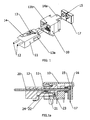
- the basic principle of the hybrid connector is Fig. 1 and Fig. 1a to c which shows an RJ-45 socket 10 and a POF adapter 11 with a polymer optical fiber 12 arranged in a tube.
- the POF adapter on one side a pin 13 and a spring 14 as a locking means for a corresponding recess of a receptacle in the socket 10, which has a spring clip 14a, which holds the transceiver 15, ie a transceiver.
- the transmitter / receiver IC 16 is located directly on the front side of the POF 12, so that via the POF or the two existing POF lines, which are guided side by side, each receiving light signals and can be sent via a light emitting diode (LED) again.
- LED light emitting diode
- guides 13a are provided on the side of the adapter 11, which are longitudinally movable in corresponding grooves of the bushing 10 accurately executable.
- Reference numerals 17 and 18 designate the respective electrical connection legs of the transceiver and the RJ-45 interface.
- the electrical connection legs 18 are about eight adjacent contact springs 19 led to the copper cables of the RJ-45 jack.
- the peculiarity of the present invention lies in the fact that in the middle of the RJ-45 socket, a connection for POF ports has been created, without having to use housing or additional plug-in connections. This can be exploited that many Ethernet switch ICs are already offered in a version in which each Ethernet LAN port can be configured either as a copper or optical port.
- each Ethernet MAC Medial Access Control
- the arrangement of the POF transceiver 15 behind the RJ-45 socket 10, the use as a copper LAN port is not limited.
- the transceiver 15 and the inserted adapter 11 form a releasable tongue and groove connection.
- the guided in respective tubes two POF 12 will form an optical coupling point between the POF end faces and the transmitting or receiving diodes of the POF transceiver 15 after snapping the connection 13, 14, which has a minimum coupling attenuation.
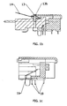
- the implementation of the two existing POF 12 shows the Fig. 1 a.
- the POF 12 has a cable sheath 20, act on the clamping fingers 21 which are part of a plastic spring 22 which are pivotable about a pivot point 23 by actuation of the lever 24.
- the plastic spring is preferably in the position in which the shell of the POF 12 is clamped, latched.
- a POF transceiver is used, which passes the transmit and receive signal to a common POF via an integrated splitter or wavelength multiplexer.
- POF ribbon cables with more than two fibers (4/8), which are either separated into individual fibers through several individual tubes to the multichannel transceiver or in combination by a rectangular in cross-section or one of the POF jacket silhouette adapted channel to the multi-channel Transceiver be led.
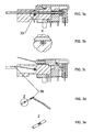
- FIG. 2a An operable by displacement along a double arrow 26 lever 25 shows Fig. 2a in which additional spring elements 27 and a latching nose 28 are provided to effect a release or clamping of the clamping spring 22.
- the plastic spring 28 operates on pressure (see Fig. 2b , Arrow 29) on the actuator plate 30th
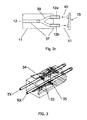
- Figure 2c shows a splitter or wavelength division multiplexer, which is integrated into an adapter 11.
- the two the transceiver 15 facing POF 12a, 12b are inserted with the adapter 11 in the RJ-45 socket.
- Both the POF 12 and the POF 12a, 12b are each plugged into a tube 37.
- splitter 39, transmit signal 40 and receive signal 41 are each plugged into a tube 37.
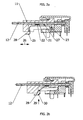
- Fig. 3 and 3a to e illustrate a clamping mechanism in which a clamping element with a rotatable eccentric 33 which is mounted in two bearings and is pivotable about a lever 36 about its longitudinal axis.
- the eccentric 33 rotates, with its rough coat or threaded surface acting on the coat of the two POF, which are marked as TX and RX lines, fixing acts.
- TX and RX lines marking as TX and RX lines
- the advantages of the clamping element after Fig. 3 consist in that the metal lever 33, 36 can be designed to save space and yet has a high stability. Optimum force transmission is possible by means of the lever 36, the metal surface of the eccentric 33 optimally cutting into the edge zone region of the plastic sheath of the POF 12 during clamping.
- the clamping element requires a minimum of space.
- Fig. 4 is shown in the form of a block diagram a monolithic integrated Ethernet switch module whose Ethernet ports are designed universally, so that over the same connection legs either an Ethernet transformer with downstream RJ-45 connector or an optical transceiver with optical interface are controlled can.
- the Ethernet switch modules have one optical FX and one copper TX-PHY per Ethernet port, whose output signals are optionally switched to the connection legs of the respective Ethernet port via an analogue multiplexer (MUX).
- MUX analogue multiplexer
- the switch position of the analogue multiplexer can be selected and thus the Ethernet port can be defined as an optical or electrical port.
- the common-multiplexed Ethernet signals can not simultaneously supply the RJ-45 copper interface and in parallel the POF transceiver via an Ethernet transformer.
- Different terminations of the differential transmit (TX + / TX-) and receive (RX + / RX-) lines are necessary.
- the optical transceivers are usually connected via a capacitor to the PHY (AC coupling), while the copper PHY are connected by DC coupling to the Ethernet transformer.
- the Ethernet switch module in Fig. 4 shows an example of the wiring of an Ethernet MAC port with a TX and an FX PHY.
- Common switch devices have at least two, but typically five, six, eight, twelve, twenty-four, or forty-eight Ethernet ports.
- MAC is in parallel with a TX and connected to an FX-PHY, which in turn supply a downstream analog multiplexer.
- the differential transmission signals of the two PHYs are switched to the common transmission lines (TX- / TX +) via the upper multiplex channel and the differential reception signals reach the copper or optical interface via the common switch connection legs (RX- / RX +) and the lower multiplex channel.
- PHY If one wishes to feed an optical POF transceiver via this multiplexed connection legs and an RJ-45 port with Ethernet data packets in parallel via a transformer, it is necessary to use a further analogue multiplexer to connect the Ethernet signals of the copper or optics -PHY again separately available.
- the signals common to the switch-multiplexed signals are split again via a broadband analogue multiplexer.
- the differential transmit and receive signals from the switch to the analog multiplexer these signals depending on the logic level of the control signal (/ SEL_POF) via the POF termination network to the POF transceiver (POF TRX) or over the RJ-45 termination network and connect the Ethernet transformer to the RJ-45 jack.
- control signal / SEL_POF
- POF TRX logic level of the control signal
- the RJ-45 jack and the POF transceiver are drawn on top of each other, like Fig. 1 can be seen, however, are the two parts in a row, the POF passes through the plugged into the RJ-45 socket POF adapter to the POF transceiver 15.
- the transceiver 15 is integrated into the RJ-45 jack, ie, fixedly mounted in the rear of the RJ-45 plastic housing.
- the transceiver 15 has several advantages. On the one hand, a cost-effective production is made possible by saving a separate component. Furthermore, only one common shield plate is required for the RJ-45 jack and the POF transceiver, so that contacting problems between the RJ-45 and the transceiver shield are avoided.
- the plastic body of an existing RJ-45 socket is extended to the rear and receives there two chambers into which a POF transmitter and a POF receiver can be inserted and locked.
- Such transmitters and receivers can be built as small-volume, cast in plastic wired components.
- the prior art shield plates customary with prior art RJ-45 are extended to include the entire plastic body of the POF transmitter or receiver. In this solution, the dimensions of the RJ-45 front and the position of the connecting legs or the RJ-45-Foot print are compatible with the RJ-45 socket without integrated POF transceiver.
- the advantage for the device manufacturer is that he can offer RJ-45 LAN ports or hybrid RJ-45 / POF ports without any changes to an existing terminal housing simply by changing the configuration of the printed circuit board.
- the hybrid RJ-45 sockets with integrated POF transceiver are realized as usual with RJ-45 sockets in single, double, quadruple and eightfold versions. These hybrid multiple sockets make it possible to build Ethernet switches that realize up to 48 hybrid RJ-45 POF ports in a 19 inch height unit.
- the required analog multiplexer is placed on the circuit board between the switch module and the hybrid connector system.
- analog multiplexer can be combined with the POF transceiver, the Ethernet transformer and the RJ-45 socket to form a single component.
- the advantage of this solution lies in the smaller number of connection legs, the elimination of individual components and the possibility of complete shielding over all integrated components, which in turn leads to better electromagnetic compatibility.
Landscapes
- Physics & Mathematics (AREA)
- General Physics & Mathematics (AREA)
- Optics & Photonics (AREA)
- Optical Couplings Of Light Guides (AREA)
Applications Claiming Priority (1)
| Application Number | Priority Date | Filing Date | Title |
|---|---|---|---|
| DE102007062658A DE102007062658A1 (de) | 2007-12-24 | 2007-12-24 | Hybrid-Steckverbindung |
Publications (1)
| Publication Number | Publication Date |
|---|---|
| EP2075604A1 true EP2075604A1 (fr) | 2009-07-01 |
Family
ID=40470003
Family Applications (1)
| Application Number | Title | Priority Date | Filing Date |
|---|---|---|---|
| EP08021955A Withdrawn EP2075604A1 (fr) | 2007-12-24 | 2008-12-18 | Connexion à fiches hybride electrique-optique du type RJ-45 |
Country Status (2)
| Country | Link |
|---|---|
| EP (1) | EP2075604A1 (fr) |
| DE (1) | DE102007062658A1 (fr) |
Cited By (4)
| Publication number | Priority date | Publication date | Assignee | Title |
|---|---|---|---|---|
| US20110243567A1 (en) * | 2010-04-05 | 2011-10-06 | Avago Technologies Fiber Ip (Singapore) Pte. Ltd. | Modular connector assembly configured with both optical and electrical connections for providing both optical and electrical communications capabilities, and a system that incorporates the assembly |
| US8376630B2 (en) | 2010-04-05 | 2013-02-19 | Avago Technologies Fiber Ip (Singapore) Pte. Ltd. | Hybrid 8P8C RJ-45 modular plug configured with both optical and electrical connections for providing both optical and electrical communications capabilities, and a method |
| GB2494264A (en) * | 2011-08-31 | 2013-03-06 | Avago Tech Ecbu Ip Sg Pte Ltd | A hybrid plug with electrical and optical connections |
| US8794850B2 (en) | 2010-04-05 | 2014-08-05 | Avago Technologies General Ip (Singapore) Pte. Ltd. | Adapter configured with both optical and electrical connections for providing both optical and electrical communications capabilities |
Citations (7)
| Publication number | Priority date | Publication date | Assignee | Title |
|---|---|---|---|---|
| WO1998018033A1 (fr) * | 1996-10-22 | 1998-04-30 | Stewart Connector Systems | Systeme d'interconnexion optique |
| DE19935996A1 (de) * | 1999-07-30 | 2001-02-01 | Siemens Ag | Hybride, modulare Datenbuchse zur Aufnahme von elektrischen und optischen Steckern |
| EP1102099A2 (fr) | 1999-11-19 | 2001-05-23 | Yazaki Corporation | Connecteur hybride |
| US6431764B1 (en) * | 1998-06-16 | 2002-08-13 | Stratos Lightwave | Optical transceiver RJ-jack with EMI shield |
| WO2003093888A1 (fr) | 2002-05-02 | 2003-11-13 | Reichle & De-Massari Ag | Connecteur enfichable hybride |
| US20050013547A1 (en) * | 2001-08-06 | 2005-01-20 | Giacomo Rossi | Device for connecting an optical fibre |
| US20050213893A1 (en) * | 2004-03-25 | 2005-09-29 | Hiroshi Hamasaki | Optical fiber connector and connecting method |
Family Cites Families (1)
| Publication number | Priority date | Publication date | Assignee | Title |
|---|---|---|---|---|
| US5896480A (en) * | 1996-10-22 | 1999-04-20 | Stewart Connector Systems, Inc. | Optical interconnection system |
-
2007
- 2007-12-24 DE DE102007062658A patent/DE102007062658A1/de not_active Withdrawn
-
2008
- 2008-12-18 EP EP08021955A patent/EP2075604A1/fr not_active Withdrawn
Patent Citations (7)
| Publication number | Priority date | Publication date | Assignee | Title |
|---|---|---|---|---|
| WO1998018033A1 (fr) * | 1996-10-22 | 1998-04-30 | Stewart Connector Systems | Systeme d'interconnexion optique |
| US6431764B1 (en) * | 1998-06-16 | 2002-08-13 | Stratos Lightwave | Optical transceiver RJ-jack with EMI shield |
| DE19935996A1 (de) * | 1999-07-30 | 2001-02-01 | Siemens Ag | Hybride, modulare Datenbuchse zur Aufnahme von elektrischen und optischen Steckern |
| EP1102099A2 (fr) | 1999-11-19 | 2001-05-23 | Yazaki Corporation | Connecteur hybride |
| US20050013547A1 (en) * | 2001-08-06 | 2005-01-20 | Giacomo Rossi | Device for connecting an optical fibre |
| WO2003093888A1 (fr) | 2002-05-02 | 2003-11-13 | Reichle & De-Massari Ag | Connecteur enfichable hybride |
| US20050213893A1 (en) * | 2004-03-25 | 2005-09-29 | Hiroshi Hamasaki | Optical fiber connector and connecting method |
Cited By (9)
| Publication number | Priority date | Publication date | Assignee | Title |
|---|---|---|---|---|
| US20110243567A1 (en) * | 2010-04-05 | 2011-10-06 | Avago Technologies Fiber Ip (Singapore) Pte. Ltd. | Modular connector assembly configured with both optical and electrical connections for providing both optical and electrical communications capabilities, and a system that incorporates the assembly |
| CN102263340A (zh) * | 2010-04-05 | 2011-11-30 | 安华高科技光纤Ip(新加坡)私人有限公司 | 模块连接器组件以及包括该组件的系统 |
| US8376630B2 (en) | 2010-04-05 | 2013-02-19 | Avago Technologies Fiber Ip (Singapore) Pte. Ltd. | Hybrid 8P8C RJ-45 modular plug configured with both optical and electrical connections for providing both optical and electrical communications capabilities, and a method |
| US8467654B2 (en) * | 2010-04-05 | 2013-06-18 | Avago Technologies General Ip (Singapore) Pte. Ltd. | Modular connector assembly configured with both optical and electrical connections for providing both optical and electrical communications capabilities, and a system that incorporates the assembly |
| US8761564B2 (en) | 2010-04-05 | 2014-06-24 | Avago Technologies General Ip (Singapore) Pte. Ltd. | Modular plug and jack connector assembly |
| CN102263340B (zh) * | 2010-04-05 | 2014-07-16 | 安华高科技通用Ip(新加坡)公司 | 模块连接器组件以及包括该组件的系统 |
| US8794850B2 (en) | 2010-04-05 | 2014-08-05 | Avago Technologies General Ip (Singapore) Pte. Ltd. | Adapter configured with both optical and electrical connections for providing both optical and electrical communications capabilities |
| GB2494264A (en) * | 2011-08-31 | 2013-03-06 | Avago Tech Ecbu Ip Sg Pte Ltd | A hybrid plug with electrical and optical connections |
| GB2494264B (en) * | 2011-08-31 | 2016-01-20 | Avago Technologies General Ip | A hybrid plug for a modular connector assembly |
Also Published As
| Publication number | Publication date |
|---|---|
| DE102007062658A1 (de) | 2009-06-25 |
Similar Documents
| Publication | Publication Date | Title |
|---|---|---|
| EP1775612B1 (fr) | Dispositif de connexion de câble optique | |
| DE60011148T2 (de) | Faseroptische verbindungsvorrichtung zur verbindung von bauteilen auf sich schneidenden ebenen | |
| DE102011079952A1 (de) | Adapter, welcher sowohl mit optischen als auch mit elektrischen Verbindungen zum Bereitstellen sowohl einer optischen als auch einer elektrischen Kommunikationsfähigkeit konfiguriert ist | |
| DE102011006586A1 (de) | Modulare Konnektorbaugruppe, welche sowohl mit optischen als auch mit elektrischen Verbindungen konfiguriert ist, zum Bereitstellen von sowohl optischen als auch elektrischen Kommunikationsfähigkeiten und System, welches die Baugruppe inkorporiert | |
| EP1504297A1 (fr) | Connecteur enfichable hybride | |
| WO2001059499A1 (fr) | Connecteur optique pour la connexion simultanee d'une pluralite de cables a fibres optiques ainsi qu'insert pour un tel connecteur | |
| EP2075604A1 (fr) | Connexion à fiches hybride electrique-optique du type RJ-45 | |
| DE202010017687U1 (de) | Anschlussdose für Glasfaserbasierte Verteilnetze | |
| DE112009002072B4 (de) | Lichtfaserkabelkonnektor mit integrierter Kabelaufteilung | |
| DE2741585B2 (de) | Einschubsteckverbindung fur Lichtwellenleiter | |
| EP2909666A1 (fr) | Dispositif de connexion | |
| DE10350954A1 (de) | Gehäuse für optische Komponenten | |
| EP0753906A2 (fr) | Connecteur électrique à fiche | |
| DE102012020589A1 (de) | Verbindungsvorrichtung | |
| WO2005045497A1 (fr) | Connecteur optique et couplage simple et double destine a recevoir un tel connecteur | |
| CH674281A5 (fr) | ||
| EP1792218A1 (fr) | Prise femelle multifonction et fiche male multifonction pour montage d'une fibre flexible | |
| DE2715846B2 (de) | Lichtkoppelndes Bauelement für gedruckte Schaltungen | |
| DE2611011A1 (de) | Optische koppelanordnung fuer systeme der optischen nachrichtentechnik | |
| DE60026604T2 (de) | Netzwerk zur verteilung von signalen an eine vielzahl von benutzern | |
| DE102005009576B4 (de) | Optische Verbinderanordnung | |
| DE4101962A1 (de) | Anordnung zur uebertragung von daten mit mindestens einem lichtwellenleiter | |
| DE102019112007A1 (de) | Steckverbinder | |
| WO2009130160A1 (fr) | Connecteur optique | |
| EP1969770B1 (fr) | Appareil de telecommunication |
Legal Events
| Date | Code | Title | Description |
|---|---|---|---|
| PUAI | Public reference made under article 153(3) epc to a published international application that has entered the european phase |
Free format text: ORIGINAL CODE: 0009012 |
|
| AK | Designated contracting states |
Kind code of ref document: A1 Designated state(s): AT BE BG CH CY CZ DE DK EE ES FI FR GB GR HR HU IE IS IT LI LT LU LV MC MT NL NO PL PT RO SE SI SK TR |
|
| AX | Request for extension of the european patent |
Extension state: AL BA MK RS |
|
| 17P | Request for examination filed |
Effective date: 20091006 |
|
| AKX | Designation fees paid |
Designated state(s): AT BE BG CH CY CZ DE DK EE ES FI FR GB GR HR HU IE IS IT LI LT LU LV MC MT NL NO PL PT RO SE SI SK TR |
|
| 17Q | First examination report despatched |
Effective date: 20131220 |
|
| STAA | Information on the status of an ep patent application or granted ep patent |
Free format text: STATUS: THE APPLICATION HAS BEEN WITHDRAWN |
|
| 18W | Application withdrawn |
Effective date: 20150331 |