EP2075555A1 - Spectroscopic module - Google Patents
Spectroscopic module Download PDFInfo
- Publication number
- EP2075555A1 EP2075555A1 EP08765192A EP08765192A EP2075555A1 EP 2075555 A1 EP2075555 A1 EP 2075555A1 EP 08765192 A EP08765192 A EP 08765192A EP 08765192 A EP08765192 A EP 08765192A EP 2075555 A1 EP2075555 A1 EP 2075555A1
- Authority
- EP
- European Patent Office
- Prior art keywords
- light
- lisht
- body portion
- detecting element
- detecting
- Prior art date
- Legal status (The legal status is an assumption and is not a legal conclusion. Google has not performed a legal analysis and makes no representation as to the accuracy of the status listed.)
- Withdrawn
Links
Images

Classifications
-
- G—PHYSICS
- G01—MEASURING; TESTING
- G01J—MEASUREMENT OF INTENSITY, VELOCITY, SPECTRAL CONTENT, POLARISATION, PHASE OR PULSE CHARACTERISTICS OF INFRARED, VISIBLE OR ULTRAVIOLET LIGHT; COLORIMETRY; RADIATION PYROMETRY
- G01J3/00—Spectrometry; Spectrophotometry; Monochromators; Measuring colours
- G01J3/28—Investigating the spectrum
- G01J3/2803—Investigating the spectrum using photoelectric array detector
-
- G—PHYSICS
- G01—MEASURING; TESTING
- G01J—MEASUREMENT OF INTENSITY, VELOCITY, SPECTRAL CONTENT, POLARISATION, PHASE OR PULSE CHARACTERISTICS OF INFRARED, VISIBLE OR ULTRAVIOLET LIGHT; COLORIMETRY; RADIATION PYROMETRY
- G01J3/00—Spectrometry; Spectrophotometry; Monochromators; Measuring colours
- G01J3/02—Details
-
- G—PHYSICS
- G01—MEASURING; TESTING
- G01J—MEASUREMENT OF INTENSITY, VELOCITY, SPECTRAL CONTENT, POLARISATION, PHASE OR PULSE CHARACTERISTICS OF INFRARED, VISIBLE OR ULTRAVIOLET LIGHT; COLORIMETRY; RADIATION PYROMETRY
- G01J3/00—Spectrometry; Spectrophotometry; Monochromators; Measuring colours
- G01J3/02—Details
- G01J3/0202—Mechanical elements; Supports for optical elements
-
- G—PHYSICS
- G01—MEASURING; TESTING
- G01J—MEASUREMENT OF INTENSITY, VELOCITY, SPECTRAL CONTENT, POLARISATION, PHASE OR PULSE CHARACTERISTICS OF INFRARED, VISIBLE OR ULTRAVIOLET LIGHT; COLORIMETRY; RADIATION PYROMETRY
- G01J3/00—Spectrometry; Spectrophotometry; Monochromators; Measuring colours
- G01J3/02—Details
- G01J3/0205—Optical elements not provided otherwise, e.g. optical manifolds, diffusers, windows
- G01J3/0208—Optical elements not provided otherwise, e.g. optical manifolds, diffusers, windows using focussing or collimating elements, e.g. lenses or mirrors; performing aberration correction
-
- G—PHYSICS
- G01—MEASURING; TESTING
- G01J—MEASUREMENT OF INTENSITY, VELOCITY, SPECTRAL CONTENT, POLARISATION, PHASE OR PULSE CHARACTERISTICS OF INFRARED, VISIBLE OR ULTRAVIOLET LIGHT; COLORIMETRY; RADIATION PYROMETRY
- G01J3/00—Spectrometry; Spectrophotometry; Monochromators; Measuring colours
- G01J3/02—Details
- G01J3/0205—Optical elements not provided otherwise, e.g. optical manifolds, diffusers, windows
- G01J3/0243—Optical elements not provided otherwise, e.g. optical manifolds, diffusers, windows having a through-hole enabling the optical element to fulfil an additional optical function, e.g. a mirror or grating having a throughhole for a light collecting or light injecting optical fiber
-
- G—PHYSICS
- G01—MEASURING; TESTING
- G01J—MEASUREMENT OF INTENSITY, VELOCITY, SPECTRAL CONTENT, POLARISATION, PHASE OR PULSE CHARACTERISTICS OF INFRARED, VISIBLE OR ULTRAVIOLET LIGHT; COLORIMETRY; RADIATION PYROMETRY
- G01J3/00—Spectrometry; Spectrophotometry; Monochromators; Measuring colours
- G01J3/02—Details
- G01J3/0256—Compact construction
- G01J3/0259—Monolithic
-
- G—PHYSICS
- G01—MEASURING; TESTING
- G01J—MEASUREMENT OF INTENSITY, VELOCITY, SPECTRAL CONTENT, POLARISATION, PHASE OR PULSE CHARACTERISTICS OF INFRARED, VISIBLE OR ULTRAVIOLET LIGHT; COLORIMETRY; RADIATION PYROMETRY
- G01J3/00—Spectrometry; Spectrophotometry; Monochromators; Measuring colours
- G01J3/02—Details
- G01J3/0262—Constructional arrangements for removing stray light
-
- G—PHYSICS
- G01—MEASURING; TESTING
- G01J—MEASUREMENT OF INTENSITY, VELOCITY, SPECTRAL CONTENT, POLARISATION, PHASE OR PULSE CHARACTERISTICS OF INFRARED, VISIBLE OR ULTRAVIOLET LIGHT; COLORIMETRY; RADIATION PYROMETRY
- G01J3/00—Spectrometry; Spectrophotometry; Monochromators; Measuring colours
- G01J3/02—Details
- G01J3/0286—Constructional arrangements for compensating for fluctuations caused by temperature, humidity or pressure, or using cooling or temperature stabilization of parts of the device; Controlling the atmosphere inside a spectrometer, e.g. vacuum
-
- G—PHYSICS
- G01—MEASURING; TESTING
- G01J—MEASUREMENT OF INTENSITY, VELOCITY, SPECTRAL CONTENT, POLARISATION, PHASE OR PULSE CHARACTERISTICS OF INFRARED, VISIBLE OR ULTRAVIOLET LIGHT; COLORIMETRY; RADIATION PYROMETRY
- G01J3/00—Spectrometry; Spectrophotometry; Monochromators; Measuring colours
- G01J3/02—Details
- G01J3/0291—Housings; Spectrometer accessories; Spatial arrangement of elements, e.g. folded path arrangements
-
- G—PHYSICS
- G01—MEASURING; TESTING
- G01J—MEASUREMENT OF INTENSITY, VELOCITY, SPECTRAL CONTENT, POLARISATION, PHASE OR PULSE CHARACTERISTICS OF INFRARED, VISIBLE OR ULTRAVIOLET LIGHT; COLORIMETRY; RADIATION PYROMETRY
- G01J3/00—Spectrometry; Spectrophotometry; Monochromators; Measuring colours
- G01J3/02—Details
- G01J3/04—Slit arrangements slit adjustment
Definitions
- the present invention relates to a spectroscopy module for dispersing light to detect the light.
- Patent Document 1 has disclosed a spectroscopy module which is provided with a light-transmitting supporting body, an incident slit portion which makes light incident into the supporting body, a concave diffraction grating for dispersing the light made incident into the supporting body to reflect the light, and a diode for detecting the light dispersed and reflected by the concave diffraction grating.
- the present invention has been made in view of the above situation, an object of which is to provide a highly reliable spectroscopy module.
- the spectroscopy module of the present invention is provided with a light-transmitting body portion, a spectroscopic portion for dispersing light made incident from a predetermined plane of the body portion into the body portion to reflect the light on the predetermined plane, a light detecting element having a lisht detecting portion for detecting the light dispersed and reflected by the spectroscopic portion and electrically connected to wiring formed on the predetermined plane by face-down bonding, an underfill material filled in the body portion side of the light detecting element and capable of transmitting the light, in which the light detecting element is provided with a light passing hole through which the light advancing to the spectroscopic portion passes and a raised portion is formed so as to enclose a light outgoing opening of the light passing hole on a plane of the body portion side of the light detecting element.
- a light passing hole through which light advancing to the spectroscopic portion passes and a lisht detecting portion for detecting light dispersed and reflected by the spectroscopic portion are formed at the light detecting element. Therefore, it is possible to prevent the deviation of relative positional relationship between the light passing hole and the lisht detecting portion.
- the light detecting element is electrically connected to wiring formed on the predetermined plane of the body portion by face-down bonding, and a light-transmitting underfill material is filled in the body portion side of the light detecting element. Therefore, the body portion and the light detecting element can be improved in mechanical strength, and light which advances between the body portion and the light detecting element can also be adjusted for the refraction index.
- the underfill material filled between the light detecting element and the body portion enters into a light passing hole of the light detecting element
- light made incident into the light passing hole may be deflected or diffused, depending on the shape of the surface on the light incident side of the underfill material inside the light passing hole.
- a raised portion is formed on a plane of the body portion side of the light detecting element so as to enclose a light outgoing opening of the light passing hole.
- the underfill material is reserved at the raised portion to prevent the underfill material from entering into the light passing hole. Therefore, light is not deflected or diffused by the underfill material but can be made incident into the body portion.
- the spectroscopy module it is possible to improve the reliability.
- the wiring has a lisht absorbing layer on a predetermined plane.
- a light reflection preventive layer can be used to prevent stray light from being reflected in a diffused manner due to the wiring.
- the lisht absorbing layer acts to suppress the generation of stray light and also absorb the stray light, thus making it possible to suppress the stray light from being made incident into the lisht detecting portion of the light detecting element.
- the raised portion is formed so as to enclose the first light passing portion when viewed from the center line of the light passing hole.
- the underfill material is prevented from entering into the first light passing portion of the lisht absorbing layer, light can be made incident into the body portion without being deflected or diffused by the underfill material.
- Fig. 1 is a plan view of a spectroscopy module of a first embodiment of the present invention.
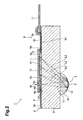
- Fig. 2 is a cross sectional view of the spectroscopy module taken along line II to II given in Fig. 1 .
- the spectroscopy module 1 is provided with a light-transmitting body portion 2, a spectroscopic portion 3 for dispersing light L1 made incident from a front plane (predetermined plane) 2a of the body portion 2 into the body portion 2 to reflect the light on the front plane 2a, and a light detecting element 4 for detecting light L2 dispersed and reflected by the spectroscopic portion 3.
- the spectroscopy module 1 is to disperse the light L1 into a plurality of lights L2 by the spectroscopic portion 3 and detect the lights L2 by the light detecting element 4, thereby measuring the wavelength distribution of the light L1 and the intensity of a specific wavelength component or the like.
- the body portion 2 is provided with a light-transmitting member 2 1 formed in a rectangular plate shape by using light-transmitting glass or a light-transmitting resin such as BK7, Pyrex (registered trade mark) or quartz and a light-transmitting member 2 2 formed at a predetermined position on the rear plane of the light-transmitting member 2 1 .
- a light-transmitting member 2 1 formed in a rectangular plate shape by using light-transmitting glass or a light-transmitting resin such as BK7, Pyrex (registered trade mark) or quartz and a light-transmitting member 2 2 formed at a predetermined position on the rear plane of the light-transmitting member 2 1 .
- the light-transmitting member 2 2 is formed by using the same material as that of the light-transmitting member 2 1 , that is, a light-transmitting organic-inorganic hybrid material or light-transmitting low-melting temperature glass for replica molding in a predetermined shape (in this instance, a shape in which a hemisphere lens is cut out by two planes approximately orthogonal to the flat plane portion thereof and also approximately parallel to each other to give the side planes), thereby acting as a lens for forming an image on a lisht detecting portion 41 of the light detecting element 4 on the basis of light L2 dispersed and reflected by the spectroscopic portion 3.
- a predetermined shape in this instance, a shape in which a hemisphere lens is cut out by two planes approximately orthogonal to the flat plane portion thereof and also approximately parallel to each other to give the side planes
- the light-transmitting member 2 2 is arranged so that the side planes are approximately parallel with the longitudinal direction of the light-transmitting member 2 1 and bonded to the light-transmitting member 2 1 with an optical resin or by direct bonding where it is made with the same material as that of the light-transmitting member 2 1 .
- the spectroscopic portion 3 is a reflection type grating having a diffracting layer 14 formed on the outer surface of the light-transmitting member 2 2 and a reflecting layer 5 formed on the outer surface of the diffracting layer 14.
- the diffracting layer 14 is a serrated cross-sectional blazed grating, a rectangular cross-sectional binary grating, a sinusoidal cross-sectional holographic grating or the like.
- the diffracting layer 14 is formed, for example, by coating a photosensitive resin on the outer surface of the light-transmitting member 2 2 and then using a light-transmitting mold (grating mold) made of quartz or the like to subject the photosensitive resin to UV curing.
- the diffracting layer 14 is made more stable when heated and cured after the UV curing.
- the reflecting layer 5 is formed in a film shape, for example, by evaporating Al, Au or the like on the outer surface of the diffracting layer 14. Further, a protective layer made with SiO 2 , MgF 2 or the like may be formed on the reflecting layer 5. It is noted that materials of the diffracting layer 14 shall not be limited to photosensitive resins but may include photosensitive glass, photosensitive organic-inorganic hybrid materials, heat-deformable resins/glass and organic-inorganic hybrid materials.
- the light detecting element 4 is provided with a lisht detecting portion 41 in which long photodiodes are arrayed one-dimensionally in a direction approximately orthogonal to the longitudinal direction thereof to detect light L2 dispersed and reflected by the spectroscopic portion 3 and a light passing hole 42 which is installed together with the lisht detecting portion 41 in a direction at which the photodiodes are arranged one dimensionally and through which light L1 advancing to the spectroscopic portion 3 passes.
- the light passing hole 42 is a slit extending in a direction approximately orthogonal to the longitudinal direction of the light-transmitting member 2 1 and formed by etching, blasting or laser processing in a state that it is positioned at a high accuracy with respect to the lisht detecting portion 41.
- the light detecting element 4 is arranged in such a manner that a direction at which the photodiodes are arrayed one dimensionally is approximately in agreement with the longitudinal direction of the light-transmitting member 2 1 and also the lisht detecting portion 41 turns to the front plane 2a of the body portion 2. It is noted that the light detecting element 4 shall not be limited to the photodiode array but may include a C-MOS image sensor, a CCD image sensor or the like.
- a wiring 9 made of a single film of Al, Au or the like or a laminated film of Ti-Pt-Au, Ti-Ni-Au, Cr-Au or the like.
- the wiring 9 is provided with a plurality of pad portions 9a arranged at the center of the light-transmitting member 2 1 , a plurality of pad portions 9b arranged at the end of the light-transmitting member 2 1 in the longitudinal direction and a plurality of connection portions 9c for connecting the corresponding pad portions 9a and the pad portions 9b.
- the wiring 9 is provided on the front plane 2a of the body portion 2 with a lisht absorbing layer 9d made of a single film of CrO or the like or a laminated film of Cr-CrO or the like.
- a lisht absorbing layer 6 so as to expose the pad portions 9a, 9b of the wiring 9 and also cover the connection portions 9c of the wiring 9.
- the lisht absorbing layer 6 is provided with a light passing portion (first light passing portion) 6a through which light L1 advancing to the spectroscopic portion 3 passes and a light passing portion (second light passing portion) 6b through which light L2 advancing to the lisht detecting portion 41 of the light detecting element 4 passes.
- the light passing portion 6a is a slit extending in a direction approximately orthogonal to the longitudinal direction of the light-transmitting member 2 1 .
- the lisht absorbing layer 6 is subjected to a predetermined-shaped patterning and formed integrally by using CrO, a CrO-containing laminated film, black resist or the like.
- An external terminal of the light detecting element 4 is electrically connected to the pad portion 9a exposed from the lisht absorbing layer 6 by face-down bonding via a bump 15 so that the light passing hole 42 opposes the light passing portion 6a of the lisht absorbing layer 6 and the lisht detecting portion 41 also opposes the light passing portion 6b of the lisht absorbing layer 6. Further, a flexible printed board 11 for taking out an output signal of the light detecting element 4 is electrically connected by wire bonding to the pad portions 9b exposed from the lisht absorbing layer 6.
- an underfill material 12 for transmitting at least light L2 is filled in the body portion 2 side (in this instance, between the light detecting element 4 and the light-transmitting member 2 1 or the lisht absorbing layer 6) of the light detecting element 4.
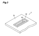
- Fig. 3 is a perspective view showing the vicinity of a light passing hole of the light detecting element of the spectroscopy module given in Fig. 1 , when viewed from the body portion.
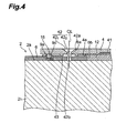
- Fig. 4 is an enlarged cross sectional view showing the vicinity of the light passing hole of the spectroscopy module given in Fig. 1 .
- the light passing hole 42 is provided with a light incident-side portion 42 1 for demarcating a light incident opening 42a from which light L1 is made incident and a light outgoing-side portion 42 2 for demarcating a light outgoing opening 42b from which light L1 is made outgoing.
- the light outgoing-side portion 42 2 is formed in a rectangular solid shape extending to a direction approximately orthogonal to the longitudinal direction of a light-transmitting member 2 1 and the light incident-side portion 42 1 is formed in a square pyramid shape widening from the light outgoing-side portion 42 2 to the opposite direction. More specifically, the light passing hole 42 is formed in such a manner that the light incident opening 42a includes the light outgoing opening 42b, when viewed from the center line (CL) thereof.
- a rectangular annular raised portion 43 is formed on a rear plane 4a of the body portion 2 side in the light detecting element 4 so as to enclose the light outgoing opening 42b.
- light L1 is made incident from the front plane 2a of the body portion 2 into the body portion 2 via the light passing hole 42 of the light detecting element 4 and the light passing portion 6a of the lisht absorbing layer 6, advancing inside the light-transmitting members 2 1 , 2 2 and arriving at the spectroscopic portion 3.
- the light L1 which has arrived at the spectroscopic portion 3 is dispersed into a plurality of lights L2 by the spectroscopic portion 3.
- the thus dispersed light L2 is reflected by the spectroscopic portion 3 on the front plane 2a side of the body portion 2, advancing inside the light-transmitting members 2 2 , 2 1 , and arriving at the lisht detecting portion 41 of the light detecting element 4 via the light passing portion 6b of the lisht absorbing layer 6.
- the light L2 which has arrived at the lisht detecting portion 41 is detected by the light detecting element 4.
- the light passing hole 42 through which light L1 advancing to the spectroscopic portion 3 passes and the lisht detecting portion 41 for detecting light L2 dispersed and reflected by the spectroscopic portion 3 are formed at the light detecting element 4 in a state that they are positioned from each other at a high accuracy. It becomes unnecessary to install different members for forming the light passing hole 42 and to position between the light passing hole 42 and the lisht detecting portion 41 (more specifically, only the spectroscopic portion 3 is positioned with respect to the light detecting element 4). Therefore, it is possible to downsize the spectroscopy module 1 at a reduced cost.
- the light detecting element 4 is electrically connected to the wiring 9 formed on the front plane 2a side of the body portion 2 by face-down bonding, and an underfill material 12 for transmitting light L1, L2 is filled in the body portion 2 side of the light detecting element 4.
- an underfill material 12 for transmitting light L1, L2 is filled in the body portion 2 side of the light detecting element 4.
- the flexible printed board 11 is directly (mechanically) connected to the light detecting element 4
- a force applied to the flexible printed board 11 at the point of using the spectroscopy module 1 is not directly transferred to the light detecting element 4, thus making it possible to prevent the light detecting element 4 from receiving loads such as stress and also downsizing the light detecting element 4.
- the underfill material 12 is filled in the body portion 2 side of the light detecting element 4, by which the body portion 2 and the light detecting element 4 can be improved in mechanical strength. It is also possible to adjust the refraction index on all channels through which light L1, L2 advancing between the body portion 2 and the light detecting element 4 pass.
- a raised portion 43 is formed on a rear plane 4a of the body portion 2 side in the light detecting element 4 so as to enclose the light outgoing opening 42b of the light passing hole 42.
- the underfill material 12 is reserved at the raised portion 43 and prevented from entering into the light passing hole 42.
- the wiring 9 is provided with a lisht absorbing layer 9d on the front plane 2a side of the body portion 2.
- the wiring 9 is attached to the body portion 2 more firmly to prevent the wiring 9 from breaking or the like.
- the lisht absorbing layer 9d can be used to prevent stray light from being reflected in a diffused manner due to the wiring 9.
- a lisht absorbing layer 6 having a light passing portion 6a through which light L1 advancing to the spectroscopic portion 3 passes and a light passing portion 6b through which light L2 advancing to the lisht detecting portion 41 of the light detecting element 4 passes.
- the lisht absorbing layer 6 is used to suppress the generation of stray light and also absorb the stray light, thus making it possible to suppress the stray light from being made incident into the lisht detecting portion 41.
- the raised portion is formed so as to enclose the light passing portion 6a, when viewed from the center line (CL) of the light passing hole 42.
- the underfill material 12 is prevented from entering into the light passing portion 6a of the lisht absorbing layer 6, and light can be made incident into the body portion 2 without being deflected or diffused by the underfill material 12.
- the lisht absorbing layer 6 may be formed on the front plane 2a of the body portion 2, and the wiring 9 may be formed on the front plane of the lisht absorbing layer 6. In this instance, even if the wiring 9 is not provided on the lisht absorbing layer 9d, it is possible to prevent stray light from being reflected in a diffused manner due to the wiring 9.
- the light-transmitting member 2 2 which acts as a lens, may be formed integrally with the diffracting layer 14 by using light-transmitting low-melting temperature glass for replica molding or the like. In this instance, it is possible to simplify the production process and also prevent the deviation of relative positional relationship between the light-transmitting member 2 2 and the diffracting layer 14.
Landscapes
- Physics & Mathematics (AREA)
- Spectroscopy & Molecular Physics (AREA)
- General Physics & Mathematics (AREA)
- Spectrometry And Color Measurement (AREA)
- Led Device Packages (AREA)
Abstract
Description
- The present invention relates to a spectroscopy module for dispersing light to detect the light.
- As conventional spectroscopy modules, there are known, for example, those disclosed in Patent Documents 1 to 3. Patent Document 1 has disclosed a spectroscopy module which is provided with a light-transmitting supporting body, an incident slit portion which makes light incident into the supporting body, a concave diffraction grating for dispersing the light made incident into the supporting body to reflect the light, and a diode for detecting the light dispersed and reflected by the concave diffraction grating.
- Patent Document 1: Japanese Published Unexamined Patent Application No.
H04-294223 - Patent Document 2: Japanese Published Unexamined Patent Application No.
2004-354176 - Patent Document 3: Japanese Published Unexamined Patent Application No.
2003-243444 - Nevertheless, in the spectroscopy module described in Patent document 1, upon attachment of the incident slit portion and the diode to the supporting body, there is a fear that a relative positional relationship between the incident slit portion and the diode may deviate, thus resulting in a decrease in reliability of the spectroscopy module.
- Now, the present invention has been made in view of the above situation, an object of which is to provide a highly reliable spectroscopy module.
- In order to attain the above object, the spectroscopy module of the present invention is provided with a light-transmitting body portion, a spectroscopic portion for dispersing light made incident from a predetermined plane of the body portion into the body portion to reflect the light on the predetermined plane, a light detecting element having a lisht detecting portion for detecting the light dispersed and reflected by the spectroscopic portion and electrically connected to wiring formed on the predetermined plane by face-down bonding, an underfill material filled in the body portion side of the light detecting element and capable of transmitting the light, in which the light detecting element is provided with a light passing hole through which the light advancing to the spectroscopic portion passes and a raised portion is formed so as to enclose a light outgoing opening of the light passing hole on a plane of the body portion side of the light detecting element.
- In the spectroscopy module, a light passing hole through which light advancing to the spectroscopic portion passes and a lisht detecting portion for detecting light dispersed and reflected by the spectroscopic portion are formed at the light detecting element. Therefore, it is possible to prevent the deviation of relative positional relationship between the light passing hole and the lisht detecting portion. Further, the light detecting element is electrically connected to wiring formed on the predetermined plane of the body portion by face-down bonding, and a light-transmitting underfill material is filled in the body portion side of the light detecting element. Therefore, the body portion and the light detecting element can be improved in mechanical strength, and light which advances between the body portion and the light detecting element can also be adjusted for the refraction index. In this instance, where the underfill material filled between the light detecting element and the body portion enters into a light passing hole of the light detecting element, there is a case that light made incident into the light passing hole may be deflected or diffused, depending on the shape of the surface on the light incident side of the underfill material inside the light passing hole. In the present invention, a raised portion is formed on a plane of the body portion side of the light detecting element so as to enclose a light outgoing opening of the light passing hole. Thereby, the underfill material is reserved at the raised portion to prevent the underfill material from entering into the light passing hole. Therefore, light is not deflected or diffused by the underfill material but can be made incident into the body portion. Thus, according to the spectroscopy module, it is possible to improve the reliability.
- In the spectroscopy module of the present invention, it is preferable that the wiring has a lisht absorbing layer on a predetermined plane. For example, where the wiring is directly formed on the predetermined plane of the body portion in order to attach the wiring to the body portion more firmly, thereby preventing the wiring from breaking or the like, a light reflection preventive layer can be used to prevent stray light from being reflected in a diffused manner due to the wiring.
- In the spectroscopy module of the present invention, it is preferable that there is formed on the predetermined plane a lisht absorbing layer having a first light passing portion through which light advancing to the spectroscopic portion passes and a second light passing portion through which light advancing to the lisht detecting portion passes. In this instance, the lisht absorbing layer acts to suppress the generation of stray light and also absorb the stray light, thus making it possible to suppress the stray light from being made incident into the lisht detecting portion of the light detecting element.
- In the spectroscopy module of the present invention, it is preferable that the raised portion is formed so as to enclose the first light passing portion when viewed from the center line of the light passing hole. In this instance, since the underfill material is prevented from entering into the first light passing portion of the lisht absorbing layer, light can be made incident into the body portion without being deflected or diffused by the underfill material.
- According to the present invention, it is possible to improve the reliability.
-
-
Fig. 1 is a plan view of a spectroscopy module of a first embodiment of the present invention. -
Fig. 2 is a cross sectional view of the spectroscopy module taken along line II to II given inFig. 1 . -
Fig. 3 is a perspective view showing the vicinity of a light passing hole of the light detecting element of the spectroscopy module given inFig. 1 , when viewed from the body portion. -
Fig. 4 is an enlarged cross sectional view showing the vicinity of a light passing hole of the spectroscopy module given inFig. 1 . -
- 1: spectroscopy module
- 2: body portion
- 2a: front plane (predetermined plane)
- 3: spectroscopic portion
- 4: light detecting element
- 4a: rear plane (plane on the body portion side)
- 6: lisht absorbing layer
- 6a: light passing portion (first light passing portion)
- 6b: light passing portion (second light passing portion)
- 9: wiring
- 9d: lisht absorbing layer
- 12: underfill material
- 16: light transmitting plate
- 41: lisht detecting portion
- 42: light passing hole
- 42b: light outgoing opening
- 43: raised portion
- CL: center line
- Hereinafter, a detailed description will be given to preferred embodiments of the present invention by referring to the drawings. It is noted that in the individual drawings, the same reference letters or numerals are given to the same and corresponding parts, with overlapping description omitted.
-
Fig. 1 is a plan view of a spectroscopy module of a first embodiment of the present invention.Fig. 2 is a cross sectional view of the spectroscopy module taken along line II to II given inFig. 1 . As shown inFig. 1 andFig. 2 , the spectroscopy module 1 is provided with a light-transmittingbody portion 2, a spectroscopic portion 3 for dispersing light L1 made incident from a front plane (predetermined plane) 2a of thebody portion 2 into thebody portion 2 to reflect the light on thefront plane 2a, and alight detecting element 4 for detecting light L2 dispersed and reflected by the spectroscopic portion 3. The spectroscopy module 1 is to disperse the light L1 into a plurality of lights L2 by the spectroscopic portion 3 and detect the lights L2 by thelight detecting element 4, thereby measuring the wavelength distribution of the light L1 and the intensity of a specific wavelength component or the like. - The
body portion 2 is provided with a light-transmittingmember 21 formed in a rectangular plate shape by using light-transmitting glass or a light-transmitting resin such as BK7, Pyrex (registered trade mark) or quartz and a light-transmittingmember 22 formed at a predetermined position on the rear plane of the light-transmittingmember 21. The light-transmittingmember 22 is formed by using the same material as that of the light-transmittingmember 21, that is, a light-transmitting organic-inorganic hybrid material or light-transmitting low-melting temperature glass for replica molding in a predetermined shape (in this instance, a shape in which a hemisphere lens is cut out by two planes approximately orthogonal to the flat plane portion thereof and also approximately parallel to each other to give the side planes), thereby acting as a lens for forming an image on alisht detecting portion 41 of thelight detecting element 4 on the basis of light L2 dispersed and reflected by the spectroscopic portion 3. The light-transmittingmember 22 is arranged so that the side planes are approximately parallel with the longitudinal direction of the light-transmittingmember 21 and bonded to the light-transmittingmember 21 with an optical resin or by direct bonding where it is made with the same material as that of the light-transmittingmember 21. - The spectroscopic portion 3 is a reflection type grating having a diffracting
layer 14 formed on the outer surface of the light-transmittingmember 22 and a reflecting layer 5 formed on the outer surface of the diffractinglayer 14. The diffractinglayer 14 is a serrated cross-sectional blazed grating, a rectangular cross-sectional binary grating, a sinusoidal cross-sectional holographic grating or the like. The diffractinglayer 14 is formed, for example, by coating a photosensitive resin on the outer surface of the light-transmittingmember 22 and then using a light-transmitting mold (grating mold) made of quartz or the like to subject the photosensitive resin to UV curing. The diffractinglayer 14 is made more stable when heated and cured after the UV curing. The reflecting layer 5 is formed in a film shape, for example, by evaporating Al, Au or the like on the outer surface of the diffractinglayer 14. Further, a protective layer made with SiO2, MgF2 or the like may be formed on the reflecting layer 5. It is noted that materials of the diffractinglayer 14 shall not be limited to photosensitive resins but may include photosensitive glass, photosensitive organic-inorganic hybrid materials, heat-deformable resins/glass and organic-inorganic hybrid materials. - The
light detecting element 4 is provided with alisht detecting portion 41 in which long photodiodes are arrayed one-dimensionally in a direction approximately orthogonal to the longitudinal direction thereof to detect light L2 dispersed and reflected by the spectroscopic portion 3 and alight passing hole 42 which is installed together with thelisht detecting portion 41 in a direction at which the photodiodes are arranged one dimensionally and through which light L1 advancing to the spectroscopic portion 3 passes. Thelight passing hole 42 is a slit extending in a direction approximately orthogonal to the longitudinal direction of the light-transmittingmember 21 and formed by etching, blasting or laser processing in a state that it is positioned at a high accuracy with respect to thelisht detecting portion 41. Thelight detecting element 4 is arranged in such a manner that a direction at which the photodiodes are arrayed one dimensionally is approximately in agreement with the longitudinal direction of the light-transmittingmember 21 and also thelisht detecting portion 41 turns to thefront plane 2a of thebody portion 2. It is noted that thelight detecting element 4 shall not be limited to the photodiode array but may include a C-MOS image sensor, a CCD image sensor or the like. - On the
front plane 2a (more specifically, the front plane of the light-transmitting member 21) of thebody portion 2, there is formed awiring 9 made of a single film of Al, Au or the like or a laminated film of Ti-Pt-Au, Ti-Ni-Au, Cr-Au or the like. Thewiring 9 is provided with a plurality ofpad portions 9a arranged at the center of the light-transmittingmember 21, a plurality ofpad portions 9b arranged at the end of the light-transmittingmember 21 in the longitudinal direction and a plurality ofconnection portions 9c for connecting thecorresponding pad portions 9a and thepad portions 9b. Further, thewiring 9 is provided on thefront plane 2a of thebody portion 2 with alisht absorbing layer 9d made of a single film of CrO or the like or a laminated film of Cr-CrO or the like. - Further, on the
front plane 2a of thebody portion 2, there is formed alisht absorbing layer 6 so as to expose thepad portions wiring 9 and also cover theconnection portions 9c of thewiring 9. Thelisht absorbing layer 6 is provided with a light passing portion (first light passing portion) 6a through which light L1 advancing to the spectroscopic portion 3 passes and a light passing portion (second light passing portion) 6b through which light L2 advancing to thelisht detecting portion 41 of thelight detecting element 4 passes. Thelight passing portion 6a is a slit extending in a direction approximately orthogonal to the longitudinal direction of the light-transmittingmember 21. Thelisht absorbing layer 6 is subjected to a predetermined-shaped patterning and formed integrally by using CrO, a CrO-containing laminated film, black resist or the like. - An external terminal of the
light detecting element 4 is electrically connected to thepad portion 9a exposed from thelisht absorbing layer 6 by face-down bonding via abump 15 so that thelight passing hole 42 opposes thelight passing portion 6a of thelisht absorbing layer 6 and thelisht detecting portion 41 also opposes thelight passing portion 6b of thelisht absorbing layer 6. Further, a flexible printedboard 11 for taking out an output signal of thelight detecting element 4 is electrically connected by wire bonding to thepad portions 9b exposed from thelisht absorbing layer 6. Then, anunderfill material 12 for transmitting at least light L2 is filled in thebody portion 2 side (in this instance, between the light detectingelement 4 and the light-transmittingmember 21 or the lisht absorbing layer 6) of thelight detecting element 4. -
Fig. 3 is a perspective view showing the vicinity of a light passing hole of the light detecting element of the spectroscopy module given inFig. 1 , when viewed from the body portion.Fig. 4 is an enlarged cross sectional view showing the vicinity of the light passing hole of the spectroscopy module given inFig. 1 . As shown inFig. 3 andFig. 4 , thelight passing hole 42 is provided with a light incident-side portion 421 for demarcating a light incident opening 42a from which light L1 is made incident and a light outgoing-side portion 422 for demarcating a lightoutgoing opening 42b from which light L1 is made outgoing. The light outgoing-side portion 422 is formed in a rectangular solid shape extending to a direction approximately orthogonal to the longitudinal direction of a light-transmittingmember 21 and the light incident-side portion 421 is formed in a square pyramid shape widening from the light outgoing-side portion 422 to the opposite direction. More specifically, thelight passing hole 42 is formed in such a manner that the light incident opening 42a includes the lightoutgoing opening 42b, when viewed from the center line (CL) thereof. - A rectangular annular raised
portion 43 is formed on arear plane 4a of thebody portion 2 side in thelight detecting element 4 so as to enclose the lightoutgoing opening 42b. A region enclosed by the raisedportion 43, when viewed from the center line (CL) of thelight passing hole 42, is greater in area than thelight passing portion 6a of thelisht absorbing layer 6. - In the above-constituted spectroscopy module 1, light L1 is made incident from the
front plane 2a of thebody portion 2 into thebody portion 2 via thelight passing hole 42 of thelight detecting element 4 and thelight passing portion 6a of thelisht absorbing layer 6, advancing inside the light-transmittingmembers front plane 2a side of thebody portion 2, advancing inside the light-transmittingmembers lisht detecting portion 41 of thelight detecting element 4 via thelight passing portion 6b of thelisht absorbing layer 6. The light L2 which has arrived at thelisht detecting portion 41 is detected by thelight detecting element 4. - As so far described, in the spectroscopy module 1, the
light passing hole 42 through which light L1 advancing to the spectroscopic portion 3 passes and thelisht detecting portion 41 for detecting light L2 dispersed and reflected by the spectroscopic portion 3 are formed at thelight detecting element 4 in a state that they are positioned from each other at a high accuracy. It becomes unnecessary to install different members for forming thelight passing hole 42 and to position between the light passinghole 42 and the lisht detecting portion 41 (more specifically, only the spectroscopic portion 3 is positioned with respect to the light detecting element 4). Therefore, it is possible to downsize the spectroscopy module 1 at a reduced cost. - Further, in the spectroscopy module 1, the
light detecting element 4 is electrically connected to thewiring 9 formed on thefront plane 2a side of thebody portion 2 by face-down bonding, and anunderfill material 12 for transmitting light L1, L2 is filled in thebody portion 2 side of thelight detecting element 4. As described so far, such a constitution is provided that thelight detecting element 4 is electrically connected externally via thewiring 9 formed at thebody portion 2. Thereby, for example, in a case where the flexible printedboard 11 is directly (mechanically) connected to thelight detecting element 4, a force applied to the flexible printedboard 11 at the point of using the spectroscopy module 1 is not directly transferred to thelight detecting element 4, thus making it possible to prevent thelight detecting element 4 from receiving loads such as stress and also downsizing thelight detecting element 4. Further, theunderfill material 12 is filled in thebody portion 2 side of thelight detecting element 4, by which thebody portion 2 and thelight detecting element 4 can be improved in mechanical strength. It is also possible to adjust the refraction index on all channels through which light L1, L2 advancing between thebody portion 2 and thelight detecting element 4 pass. - Further, in the spectroscopy module 1, a raised
portion 43 is formed on arear plane 4a of thebody portion 2 side in thelight detecting element 4 so as to enclose the lightoutgoing opening 42b of thelight passing hole 42. Thereby, theunderfill material 12 is reserved at the raisedportion 43 and prevented from entering into thelight passing hole 42. Thus, light can be made incident into thebody portion 2, without being deflected or diffused by theunderfill material 12. - Further, in the spectroscopy module 1, the
wiring 9 is provided with alisht absorbing layer 9d on thefront plane 2a side of thebody portion 2. Thereby, thewiring 9 is attached to thebody portion 2 more firmly to prevent thewiring 9 from breaking or the like. Thus, even if thewiring 9 is formed directly on thefront plane 2a of thebody portion 2, thelisht absorbing layer 9d can be used to prevent stray light from being reflected in a diffused manner due to thewiring 9. - Still further, in the spectroscopy module 1, formed on the
front plane 2a of thebody portion 2 is alisht absorbing layer 6 having alight passing portion 6a through which light L1 advancing to the spectroscopic portion 3 passes and alight passing portion 6b through which light L2 advancing to thelisht detecting portion 41 of thelight detecting element 4 passes. Thelisht absorbing layer 6 is used to suppress the generation of stray light and also absorb the stray light, thus making it possible to suppress the stray light from being made incident into thelisht detecting portion 41. - In addition, in the spectroscopy module 1, the raised portion is formed so as to enclose the
light passing portion 6a, when viewed from the center line (CL) of thelight passing hole 42. Thereby, theunderfill material 12 is prevented from entering into thelight passing portion 6a of thelisht absorbing layer 6, and light can be made incident into thebody portion 2 without being deflected or diffused by theunderfill material 12. - The present invention shall not be limited to the above-described embodiments.
- For example, the
lisht absorbing layer 6 may be formed on thefront plane 2a of thebody portion 2, and thewiring 9 may be formed on the front plane of thelisht absorbing layer 6. In this instance, even if thewiring 9 is not provided on thelisht absorbing layer 9d, it is possible to prevent stray light from being reflected in a diffused manner due to thewiring 9. - Further, the light-transmitting
member 22, which acts as a lens, may be formed integrally with the diffractinglayer 14 by using light-transmitting low-melting temperature glass for replica molding or the like. In this instance, it is possible to simplify the production process and also prevent the deviation of relative positional relationship between the light-transmittingmember 22 and the diffractinglayer 14. - According to the present invention, it is possible to improve the reliability.
Claims (4)
- A spectroscopy module comprising: a light-transmitting body portion;a spectroscopic portion for dispersing light made incident from a predetermined plane of the body portion into the body portion to reflect the light on the predetermined plane;a lisht detecting element having a lisht detecting portion for detecting the light dispersed and reflected by the spectroscopic portion and electrically connected to wiring formed on the predetermined plane by face-down bonding; andan underfill material filled in the body portion side of the lisht detecting element and capable of transmitting the light;wherein the lisht detecting element is provided with a light passing hole through which the light advancing into the spectroscopic portion passes,and a raised portion is formed so as to enclose a light outgoing opening of the light passing hole on a plane of the body portion side of the lisht detecting element.
- The spectroscopy module as set forth in claim 1, wherein the wiring is provided on the predetermined plane with a lisht absorbing layer.
- The spectroscopy module as set forth in claim 1, wherein a light absorbing layer having a first light passing portion through which the light advancing into the spectroscopic portion passes and a second light passing portion through which the light advancing into the lisht detecting portion passes is formed on the predetermined plane.
- The spectroscopy module as set forth in claim 3, wherein the raised portion is formed so as to enclose the first light passing portion when viewed from the center line of the light passing hole.
Applications Claiming Priority (7)
| Application Number | Priority Date | Filing Date | Title |
|---|---|---|---|
| JP2007153039 | 2007-06-08 | ||
| JP2007153029 | 2007-06-08 | ||
| JP2007152966A JP4891840B2 (en) | 2007-06-08 | 2007-06-08 | Spectroscopic module |
| JP2007153019A JP4891841B2 (en) | 2007-06-08 | 2007-06-08 | Spectroscopic module |
| JP2007153014A JP4887221B2 (en) | 2007-06-08 | 2007-06-08 | Spectroscopic module |
| JP2007238317A JP4887251B2 (en) | 2007-09-13 | 2007-09-13 | Spectroscopic module |
| PCT/JP2008/060379 WO2008149941A1 (en) | 2007-06-08 | 2008-06-05 | Spectroscopic module |
Publications (2)
| Publication Number | Publication Date |
|---|---|
| EP2075555A1 true EP2075555A1 (en) | 2009-07-01 |
| EP2075555A4 EP2075555A4 (en) | 2014-01-01 |
Family
ID=40093751
Family Applications (1)
| Application Number | Title | Priority Date | Filing Date |
|---|---|---|---|
| EP08765192.3A Withdrawn EP2075555A4 (en) | 2007-06-08 | 2008-06-05 | Spectroscopic module |
Country Status (5)
| Country | Link |
|---|---|
| US (1) | US8049887B2 (en) |
| EP (1) | EP2075555A4 (en) |
| KR (1) | KR20100017082A (en) |
| TW (1) | TW200916739A (en) |
| WO (1) | WO2008149941A1 (en) |
Families Citing this family (12)
| Publication number | Priority date | Publication date | Assignee | Title |
|---|---|---|---|---|
| KR101503079B1 (en) | 2007-06-08 | 2015-03-16 | 하마마츠 포토닉스 가부시키가이샤 | spectroscope |
| EP2063239A4 (en) * | 2007-06-08 | 2013-12-25 | Hamamatsu Photonics Kk | Spectroscopic module |
| KR20100017083A (en) * | 2007-06-08 | 2010-02-16 | 하마마츠 포토닉스 가부시키가이샤 | Spectroscopic module |
| JP4891841B2 (en) | 2007-06-08 | 2012-03-07 | 浜松ホトニクス株式会社 | Spectroscopic module |
| JP4891840B2 (en) * | 2007-06-08 | 2012-03-07 | 浜松ホトニクス株式会社 | Spectroscopic module |
| JP4887221B2 (en) * | 2007-06-08 | 2012-02-29 | 浜松ホトニクス株式会社 | Spectroscopic module |
| JP5205238B2 (en) * | 2008-05-15 | 2013-06-05 | 浜松ホトニクス株式会社 | Spectroscopic module |
| JP5415060B2 (en) * | 2008-05-15 | 2014-02-12 | 浜松ホトニクス株式会社 | Spectroscopic module |
| TWI453380B (en) * | 2011-11-18 | 2014-09-21 | Wang Sheng | Method of manufacturing spectrometer |
| GB2508376A (en) | 2012-11-29 | 2014-06-04 | Ibm | Optical spectrometer comprising an adjustably strained photodiode |
| JP6251073B2 (en) * | 2014-02-05 | 2017-12-20 | 浜松ホトニクス株式会社 | Spectrometer and method of manufacturing the spectrometer |
| EP3372966B1 (en) * | 2017-03-10 | 2021-09-01 | Hitachi High-Tech Analytical Science Limited | A portable analyzer using optical emission spectoscopy |
Family Cites Families (43)
| Publication number | Priority date | Publication date | Assignee | Title |
|---|---|---|---|---|
| JPS54143685A (en) | 1978-04-29 | 1979-11-09 | Ritsuo Hasumi | Compact spectroscope for digital light wavemeter |
| DE3122781A1 (en) * | 1981-06-09 | 1982-12-30 | Licentia Patent-Verwaltungs-Gmbh, 6000 Frankfurt | "WAVELENGTH MULTIPLEXER OR WAVELENGTH MULTIPLEXER" |
| JPS626126A (en) | 1985-07-03 | 1987-01-13 | Shimadzu Corp | Sensor for optical spectrum analysis |
| DE3611246A1 (en) | 1986-04-04 | 1987-10-15 | Kernforschungsz Karlsruhe | METHOD FOR PRODUCING A PASSIVE OPTICAL COMPONENT WITH ONE OR MORE ECHELETTE GRIDS, AND COMPONENT PRODUCED BY THIS METHOD |
| JPS63229765A (en) | 1987-03-18 | 1988-09-26 | Fujitsu Ltd | Detector for infrared rays |
| JPH03119917A (en) | 1989-09-30 | 1991-05-22 | Iseki & Co Ltd | Grass reaper in mower |
| US5026160A (en) * | 1989-10-04 | 1991-06-25 | The United States Of America As Represented By The Secretary Of The Navy | Monolithic optical programmable spectrograph (MOPS) |
| DE4038638A1 (en) | 1990-12-04 | 1992-06-11 | Zeiss Carl Fa | DIODE LINE SPECTROMETER |
| JP3375147B2 (en) | 1992-05-26 | 2003-02-10 | 浜松ホトニクス株式会社 | Semiconductor photodetector |
| JP2713838B2 (en) | 1992-10-15 | 1998-02-16 | 浜松ホトニクス株式会社 | Spectral imaging sensor |
| JPH06229829A (en) | 1993-02-04 | 1994-08-19 | Olympus Optical Co Ltd | Photoreceptor element array |
| JPH08145794A (en) | 1994-11-17 | 1996-06-07 | Shimadzu Corp | Spectroscope |
| US6224912B1 (en) | 1996-04-03 | 2001-05-01 | The Rogo Institute | Cancer-cell proliferation-suppressing material produced by cancer cells restricted by entrapment |
| US6303934B1 (en) * | 1997-04-10 | 2001-10-16 | James T. Daly | Monolithic infrared spectrometer apparatus and methods |
| DE19717015A1 (en) | 1997-04-23 | 1998-10-29 | Inst Mikrotechnik Mainz Gmbh | Miniaturized optical component and method for its production |
| EP0942267B1 (en) * | 1998-03-11 | 2006-08-30 | Gretag-Macbeth AG | Spectrometer |
| US6181418B1 (en) * | 1998-03-12 | 2001-01-30 | Gretag Macbeth Llc | Concentric spectrometer |
| EP1144965B1 (en) * | 1999-01-08 | 2004-11-24 | Ibsen Photonics A/S | Spectrometer |
| EP1041372B1 (en) | 1999-04-01 | 2006-03-01 | Gretag-Macbeth AG | Spectrometer |
| WO2002004901A1 (en) * | 2000-07-11 | 2002-01-17 | Adc Telecommunications, Inc. | Monitoring apparatus for optical transmission systems |
| US6657723B2 (en) | 2000-12-13 | 2003-12-02 | International Business Machines Corporation | Multimode planar spectrographs for wavelength demultiplexing and methods of fabrication |
| JP4236418B2 (en) | 2001-05-09 | 2009-03-11 | 日本板硝子株式会社 | Resin erecting lens array and manufacturing method thereof |
| EP1415191A1 (en) | 2001-08-02 | 2004-05-06 | Aegis Semiconductor | Tunable optical instruments |
| JP2003139611A (en) | 2001-11-06 | 2003-05-14 | Olympus Optical Co Ltd | Spectrophotometer |
| JP3912111B2 (en) | 2002-01-09 | 2007-05-09 | 富士通株式会社 | Wavelength multiplexing bidirectional optical transmission module |
| JP3818441B2 (en) | 2002-02-20 | 2006-09-06 | 日本電信電話株式会社 | Substrate mounting structure and semiconductor device |
| JP2003318478A (en) | 2002-04-26 | 2003-11-07 | Sumitomo Electric Ind Ltd | Optical communication device |
| JP2004191246A (en) * | 2002-12-12 | 2004-07-08 | Matsushita Electric Ind Co Ltd | Unevenness detection sensor |
| DE10304312A1 (en) * | 2003-02-04 | 2004-08-12 | Carl Zeiss Jena Gmbh | Compact spectrometer |
| JP2004309146A (en) * | 2003-04-02 | 2004-11-04 | Olympus Corp | Spectrophotometer |
| JP4409860B2 (en) * | 2003-05-28 | 2010-02-03 | 浜松ホトニクス株式会社 | Spectrometer using photodetector |
| JP4627410B2 (en) * | 2004-04-20 | 2011-02-09 | 浜松ホトニクス株式会社 | Measuring device using a spectrometer |
| JP4473665B2 (en) * | 2004-07-16 | 2010-06-02 | 浜松ホトニクス株式会社 | Spectrometer |
| CN1800941B (en) | 2005-01-06 | 2010-05-12 | 群康科技(深圳)有限公司 | Backlight module assembly |
| US7697137B2 (en) * | 2006-04-28 | 2010-04-13 | Corning Incorporated | Monolithic Offner spectrometer |
| JP4887221B2 (en) | 2007-06-08 | 2012-02-29 | 浜松ホトニクス株式会社 | Spectroscopic module |
| EP2063239A4 (en) * | 2007-06-08 | 2013-12-25 | Hamamatsu Photonics Kk | Spectroscopic module |
| KR101503079B1 (en) | 2007-06-08 | 2015-03-16 | 하마마츠 포토닉스 가부시키가이샤 | spectroscope |
| JP4891841B2 (en) * | 2007-06-08 | 2012-03-07 | 浜松ホトニクス株式会社 | Spectroscopic module |
| KR20100017083A (en) | 2007-06-08 | 2010-02-16 | 하마마츠 포토닉스 가부시키가이샤 | Spectroscopic module |
| JP4891840B2 (en) | 2007-06-08 | 2012-03-07 | 浜松ホトニクス株式会社 | Spectroscopic module |
| JP5415060B2 (en) * | 2008-05-15 | 2014-02-12 | 浜松ホトニクス株式会社 | Spectroscopic module |
| JP5205238B2 (en) * | 2008-05-15 | 2013-06-05 | 浜松ホトニクス株式会社 | Spectroscopic module |
-
2008
- 2008-06-05 US US12/377,314 patent/US8049887B2/en not_active Expired - Fee Related
- 2008-06-05 WO PCT/JP2008/060379 patent/WO2008149941A1/en not_active Ceased
- 2008-06-05 KR KR1020097000554A patent/KR20100017082A/en not_active Withdrawn
- 2008-06-05 EP EP08765192.3A patent/EP2075555A4/en not_active Withdrawn
- 2008-06-06 TW TW097121327A patent/TW200916739A/en unknown
Also Published As
| Publication number | Publication date |
|---|---|
| EP2075555A4 (en) | 2014-01-01 |
| TW200916739A (en) | 2009-04-16 |
| US8049887B2 (en) | 2011-11-01 |
| KR20100017082A (en) | 2010-02-16 |
| US20100238439A1 (en) | 2010-09-23 |
| WO2008149941A1 (en) | 2008-12-11 |
Similar Documents
| Publication | Publication Date | Title |
|---|---|---|
| US8068223B2 (en) | Spectroscopic module | |
| US8045155B2 (en) | Spectroscopic module | |
| US8049887B2 (en) | Spectroscopic module | |
| EP2154498B1 (en) | Spectroscopic module | |
| EP3088854B1 (en) | Spectrometer | |
| US8368885B2 (en) | Spectroscopic module | |
| EP2048484B1 (en) | Spectroscopic module | |
| EP2801802A1 (en) | Spectroscopy module | |
| JP4887251B2 (en) | Spectroscopic module | |
| EP2474818A1 (en) | Spectral module | |
| JP4887250B2 (en) | Spectroscopic module | |
| JP4980184B2 (en) | Spectroscopic module | |
| JP5113947B2 (en) | Spectroscopic module | |
| JP5825880B2 (en) | Spectroscopic module |
Legal Events
| Date | Code | Title | Description |
|---|---|---|---|
| PUAI | Public reference made under article 153(3) epc to a published international application that has entered the european phase |
Free format text: ORIGINAL CODE: 0009012 |
|
| 17P | Request for examination filed |
Effective date: 20090213 |
|
| AK | Designated contracting states |
Kind code of ref document: A1 Designated state(s): AT BE BG CH CY CZ DE DK EE ES FI FR GB GR HR HU IE IS IT LI LT LU LV MC MT NL NO PL PT RO SE SI SK TR |
|
| AX | Request for extension of the european patent |
Extension state: AL BA MK RS |
|
| DAX | Request for extension of the european patent (deleted) | ||
| RBV | Designated contracting states (corrected) |
Designated state(s): CH DE FR GB LI |
|
| A4 | Supplementary search report drawn up and despatched |
Effective date: 20131204 |
|
| RIC1 | Information provided on ipc code assigned before grant |
Ipc: G01J 3/02 20060101AFI20131128BHEP |
|
| 17Q | First examination report despatched |
Effective date: 20131217 |
|
| STAA | Information on the status of an ep patent application or granted ep patent |
Free format text: STATUS: THE APPLICATION IS DEEMED TO BE WITHDRAWN |
|
| 18D | Application deemed to be withdrawn |
Effective date: 20140429 |